9 minute read
2.3 Removing and installing sealing flange on gearbox side


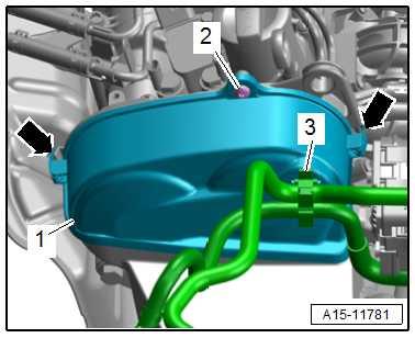
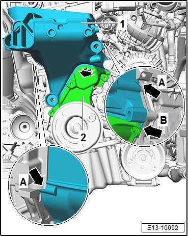
– Detach hoses from retainer -3-.
– Remove bolt -2-.
– Release clips -arrows-, and remove upper toothed belt guard -1-.
– Remove tensioner for poly V-belt ⇒ “1.3 Removing and installing tensioner for poly V-belt”, page 116 .
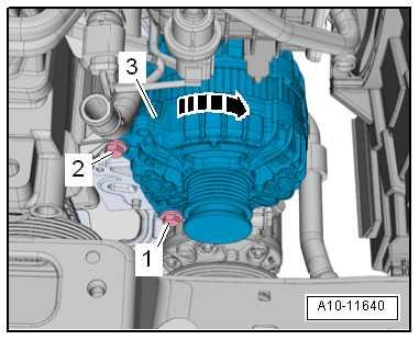
– Loosen bolt -1-, but do not unscrew.
– Remove bolt -2-.
– Swivel alternator -3- -in the direction of the arrow-.
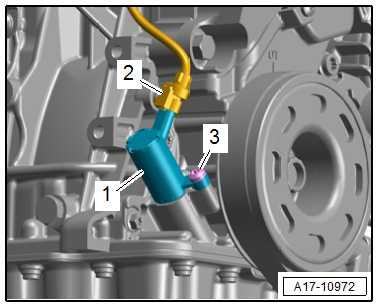
– Unplug electrical connector -2-.
Note
-Items 1, 3- can be disregarded.
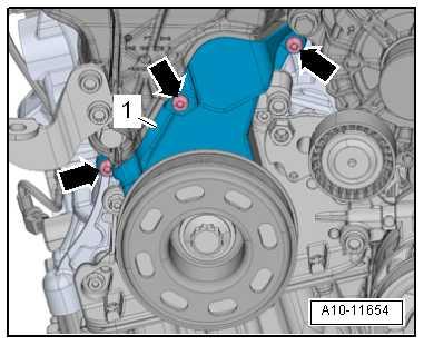
– Remove bolts -arrows- for toothed belt cover (bottom) -1-.
Protected by copyright. Copying for private or commercial purposes, in part or in whole, is not permitted unless authorised by SEAT S.A. SEAT S.A does not guarantee or accept any liability with respect to the correctness of information in this document. Copyright by SEAT S.A.

– Unscrew bolts -1, 2, 3-.
– Separate lower protector -2- -in the direction of the arrow- to free the assembly support -1-. – Separate and free the engine support, following points -arrows A, B-, remove engine support upwards to make space in the upper area. Installing Installation is in the reverse sequence of removal. Specified torques ♦ Securing bolts for engine mounting and console for engine mounting ⇒ “2.1.3 Assembly overview - assembly mountings, Toledo 2013, Ibiza 2016”, page 72 ♦ Securing bolts for tensioning roller ⇒ “1.1 Assembly overview - poly V-belt drive”, page 109 ♦ Securing bolts for lower toothed belt guard ⇒ “2.1 Assembly overview - toothed belt cover”, page 173 ♦ Securing bolts for coolant pipe ⇒ “3.1 Assembly overview - coolant pipes”, page 302 ♦ Securing bolt for air filter housing ⇒ “3.1.3 Assembly overview - air filter housing, Toledo 2013, Ibiza 2016”, page 396 ♦ Securing bolts for bracket ⇒ “2.1 Assembly overview - emission control”, page 455 ♦ Securing bolts of alternator ⇒ Electrical system; Rep. gr. 27 ; Alternator; Assembly overview - alternator . ♦ Noise insulation assembly bolts ⇒ General body repairs, ex‐terior; Rep. gr. 50 ; Underbody protection; Assembly overview – underbody protection .
Protected by copyright. Copying for private or commercial purposes, in part or in whole, is not permitted unless authorised by SEAT S.A. SEAT S.A does not guarantee or accept any liability with respect to the correctness of information in this document. Copyright by SEAT S.A.
1.6 Renewing crankshaft oil seal - belt pul‐ley end
Special tools and workshop equipment required
♦ Assembly tool - T10485-
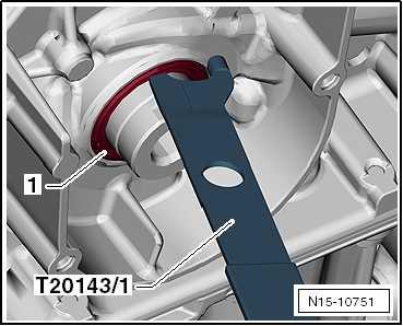
♦ Puller hooks - T20143-
Procedure
– Remove camshaft toothed belt ⇒ “2.7 Removing toothed belt from camshaft”, page 198 .
Note
Protected by copyright. Copying for private or commercial purposes, in part or in whole, is not permitted unless authorised by SEAT S.A. SEAT S.A does not guarantee or accept any liability with respect to the correctness of information in this document. Copyright by SEAT S.A.
To avoid disturbing valve timing, do not turn crankshaft out of “TDC” position when poly V-belt pulley is removed.
– Remove seal -1- using extractor hook - T20143/1- .
Installing – Clean contact surface and sealing surface.
Note
Do not lubricate new oil seal.
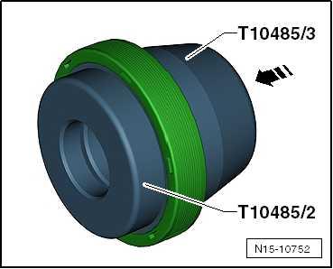
– Mount assembly sleeves - T10485/2- and -T10485/3- in -direction of arrow-.
• Installation position: The closed side of the oil seal faces the guide sleeve. – Fit new seal in direction of -arrow- over fitting sleeve T10485/3- onto assembly sleeve - T10485/2- .
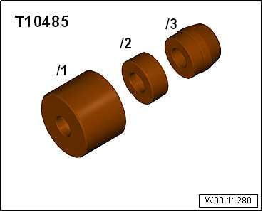

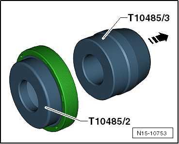
– Pull off assembly sleeve - T10485/3- in -direction of arrow-.
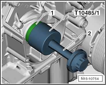
– Fit assembly sleeve - T10485/2- with seal -1- onto crankshaft journal. – Draw in thrust piece - T10485/1- to stop with securing bolt of vibration damper -2-.
– Fit crankshaft sprocket onto crankshaft. • Contact surface between poly V-belt pulley and crankshaft sprocket must be free of oil and grease. • The machined surface -arrow- of crankshaft pulley must be positioned over the machined surface of the crankshaft jour‐nal.
– Install notched belt (adjusting valve timing) ⇒ “2.7 Removing toothed belt from camshaft”, page 198
Note
After completing work, it is essential to make sure that the cam‐shaft clamp - T10477- has been removed.
Assemble in reverse order of dismantling. Specified torques ♦ Crankcase plug: 30 Nm.

Protected by copyright. Copying for private or commercial purposes, in part or in whole, is not permitted unless authorised by SEAT S.A. SEAT S.A does not guarantee or accept any liability with respect to the correctness of information in this document. Copyright by SEAT S.A.
2 Cylinder block, gearbox end
⇒ “2.1 Assembly overview - cylinder block, gearbox end”, page 135 ⇒ “2.2 Removing and installing flywheel”, page 136 ⇒ “2.3 Removing and installing sealing flange on gearbox side”, page 137
Note
For assembly work, secure engine to engine and gearbox support ⇒ “1.3 Securing engine on engine and gearbox support”, page 50 .
1 - Bolt ❑ Renew after removal ❑ 60 Nm +90°
2 - Flywheel ❑ Removing and installing ⇒ “2.2 Removing and in‐stalling flywheel”, page 136 ❑ Fitting possible in one position only. 3 - Engine speed sender G28❑ Removing and installing ⇒ “1.5 Removing and in‐stalling engine speed sender G28 ”, page 470 ❑ Assembly overview ⇒ “1.1 Assembly over‐view - ignition system”, page 464 4 - Bolt ❑ Specified torque ⇒ Item 15 (page 465) 5 - Locking pin ❑ 2 off
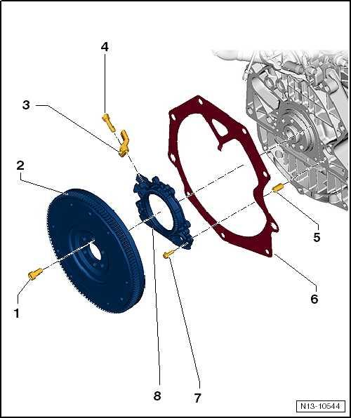
6 - Backing plate
Protected by copyright. Copying for private or commercial purposes, in part or in whole, is not permitted unless authorised by SEAT S.A. SEAT S.A does not guarantee or accept any liability with ❑ Do not damage or bend when assembling. ❑ Installing ⇒ page 136 respect to the correctness of information in this document. Copyright by SEAT S.A. 7 - Bolt ❑ Specified torque and tightening sequence ⇒ page 136 8 - Sealing flange with sender wheel and oil seal ❑ Renew sealing flange complete with oil seal and sender wheel only. ❑ With seal. ❑ Renewing ⇒ “2.3 Removing and installing sealing flange on gearbox side”, page 137
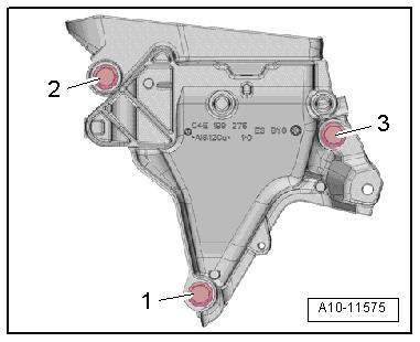
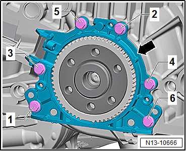
Sealing flange on gearbox side - specified torque and tightening sequence – Tighten bolts -1- to -6- in stages as follows:
Stage Bolts Specified torque
1.
2. -1- to -6- Screw in by hand as far as stop
-1- to -6- In diagonal sequence and in stages; final torque 10 Nm
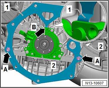
Installing intermediate plate – Attach intermediate plate -1- to sealing flange -2- -arrow B-. – Slide intermediate plate onto dowel sleeves -arrows A-.
2.2 Removing and installing flywheel
Special tools and workshop equipment required ♦ Torque wrench - V.A.G 1332-
Protected by copyright. Copying for private or commercial purposes, in part or in whole, is not permitted unless authorised by SEAT S.A. SEAT S.A does not guarantee or accept any liability with respect to the correctness of information in this document. Copyright by SEAT S.A.
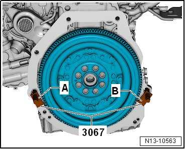
♦ Counter-hold tool - 3067-
Removing • Gearbox removed ⇒ 5-speed manual transmission 0DF; Rep. gr. 34 ; Transmission: remove and install . • Clutch release plate removed ⇒ 5-speed manual transmission 0DF; Rep. gr. 30 ; Clutch; remove and install clutch . • Screw out bolts -B- not with an air wrench or power impact wrench but by hand. • When removing the bolts, make sure that the bolt heads do not come into contact with the flywheel. • Rotate dual-mass flywheel -A- so that bolts -B- align centrally with the holes -arrows-.
– Insert counterhold tool - 3067- into hole -item B- in cylinder block.
– Loosen and remove flywheel bolts. Installing Install in reverse order of removal, observing the following:
Note
♦ If a further tightening angle is specified for certain bolts, these must be renewed.
♦ Flywheel with sender wheel can only be fitted in one position.
– Insert counter-hold tool - 3067- in hole in cylinder block -item A-.
Specified torques ♦ ⇒ “2.1 Assembly overview - cylinder block, gearbox end”, page 135

Special tools and workshop equipment required ♦ Open ring spanner - V.A.G 1332/11-
Protected by copyright. Copying for private or commercial purposes, in part or in whole, is not permitted unless authorised by SEAT S.A. SEAT S.A does not guarantee or accept any liability with respect to the correctness of information in this document. Copyright by SEAT S.A.

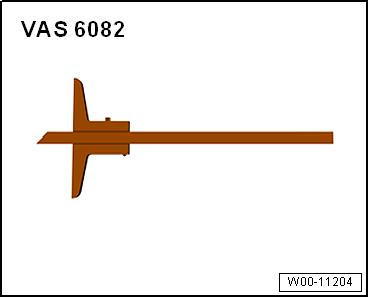
♦ Depth gauge - VAS 6082-
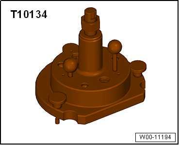
♦ Assembly tool - T10134-
♦ Bolt M6×35 (qty. 3) ♦ Hexagon key Procedure
Protected by copyright. Copying for private or commercial purposes, in part or in whole, is not permitted unless authorised by SEAT S.A. SEAT S.A does not guarantee or accept any liability with respect to the correctness of information in this document. Copyright by SEAT S.A.
Ateca, Leon 2013, Ibiza 2018, Arona
– Remove nose insulation ⇒ General body repairs, exterior; Rep. gr. 66 ; Noise insulation; Assembly overview - noise in‐sulation .
Toledo 2013, Ibiza 2016
– Remove noise insulation ⇒ General body repairs, exterior; Rep. gr. 50 ; Underbody protection; Underbody protection –assembly overview . Continued for all vehicles:
– Removing gearbox ⇒ Rep. gr. 34 ; Removing and installing gearbox . – Remove clutch ⇒ Rep. gr. 30 ; Removing and installing clutch .
– Remove flywheel ⇒ “2.2 Removing and installing flywheel”, page 136 .


