3 minute read
1.2 Separating engine and gearbox


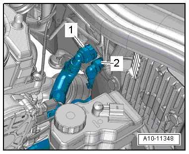
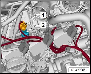
– Disconnect coolant hoses from heat exchanger for heater. Lift retaining clips -1, 2- to do this.
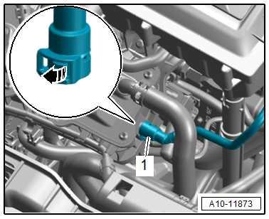
– Release catch -arrow- and disconnect vacuum hose -1-.
– Release hose clip -2- and remove coolant hose.
Note
Protected by copyright. Copying for private or commercial purposes, in part or in whole, is not permitted unless authorised by SEAT S.A. SEAT S.A does not guarantee or accept any liability with respect to the correctness of information in this document. Copyright by SEAT S.A.
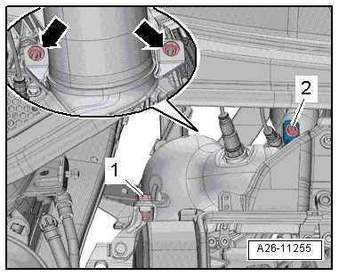
Disregard -item 1-.


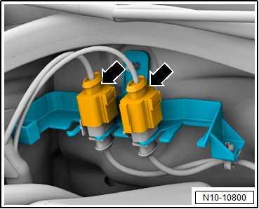
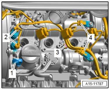
– Disconnect connectors -arrows-, and unclip wiring harness from retainer.
– Unclip line guides for lambda probes from vehicle.
For vehicles with particulate filter – Disconnect connector -1- from exhaust gas pressure sensor 1 - G450- -2-.
Continued for all vehicles
– Separate connectors: ♦ -2- for camshaft control valve 1 - N205- / for exhaust camshaft control valve 1 - N318-
♦ -4- for Hall sender - G40- / Hall sender 3 - G163-
– Remove radiator cowl ⇒ “4.5.3 Radiator cowl - removing and installing, Toledo 2013, Ibiza 2016”, page 339 .
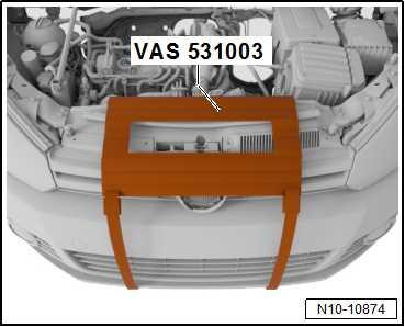
– Cover radiator using protective mat - VAS 531003- . – Remove front wheels.
– Remove gear selector cable and gate selector cable from gearbox, unbolt cable support bracket, and lay it to one side together with cables ⇒ Rep. gr. 34 ; Selector mechanism; Assembly overview - selector mechanism .
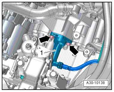
– Unscrew bolts -arrows-, remove clutch slave cylinder -1-, and lay it aside. Do not open hydraulic system.
Note
Protected by copyright. Copying for private or commercial purposes, in part or in whole, is not permitted unless authorised by SEAT S.A. SEAT S.A does not guarantee or accept any liability with respect to the correctness of information in this document. Copyright by SEAT S.A.
Do not press clutch pedal when clutch slave cylinder is removed.
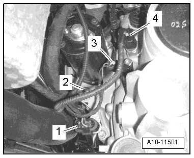
– Disconnect connectors at front of gearbox: 2 - for starter
3 - for gearbox neutral position sender - G701-
4 - for reversing light switch - F4– Remove electrical connector -1- from bracket and separate.
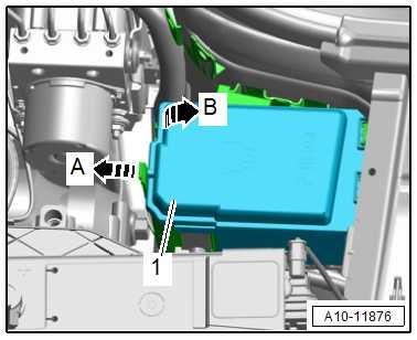
– Release catches -arrow A-.
– Open electronics box cover -1-, and remove it in direction of -arrow B-.
– Release and pull off lower connector -1- on engine control unit - J623- ⇒ “6 Engine (motor) control unit”, page 412 .
– Disconnect electrical connector -4-.
– Unscrew bolts -2 and 3-, remove wires, and lay them to one side.
– Detach engine wiring harness -arrows- using removal lever 80-200- , and place it on engine.
Note
Protected by copyright. Copying for private or commercial purposes, in part or in whole, is not permitted unless authorised by SEAT S.A. SEAT S.A does not guarantee or accept any liability with respect to the correctness of information in this document. Copyright by SEAT S.A.

Disregard -item 1-.
– Unscrew bolt -2-; remove screw-type clip. – Unscrew bolt -1- and nuts -arrows-, and secure catalytic con‐verter to vehicle.