
21 minute read
2.5 Supporting engine in installation position


♦ Torque wrench - V.A.G 1332-
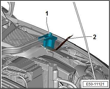
Removing – Remove battery tray ⇒ Electrical system; Rep. gr. 27 ; battery; battery tray: remove and install .
Note
Different types of brackets are fitted depending on version.
Protected by copyright. Copying for private or commercial purposes, in part or in whole, is not Ibiza 2018 permitted unless authorised by SEAT S.A. SEAT S.A does not guarantee or accept any liability with respect to the correctness of information in this document. Copyright by SEAT S.A. – Support engine in its installation position ⇒ “2.5.3 Supporting engine in installation position, Ibiza 2018”, page 93 . Arona
– Support engine in its installation position ⇒ “2.5.4 Supporting engine in installation position, Arona”, page 97 . Continued for all vehicles:
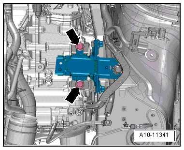
– Tighten spindle slightly to take up weight of engine/gearbox assembly; do not lift. – Loosen line guide -1- from its fastening points -arrows-, slide upwards -in direction of arrow- and secure on one side.
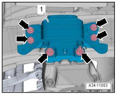
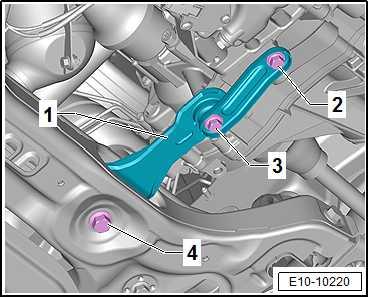
– Unscrew bolts -arrows- and remove gearbox mounting -1-. Installing Install in reverse order of removal, observing the following:
Note
♦ Risk of damage to threads by starting bolts at an angle. ♦ Renew bolts that are tightened with turning further angle after each removal.
♦ Only remove support bracket - 10 - 222 A- when bolts on as‐sembly mounting have been tightened to specified torque.
– Lift gearbox with spindle of support bracket until gearbox sup‐port makes contact with support arm of gearbox mounting. – Checking adjustment of assembly mountings ⇒ “2.7 Assembly mounting setting - checking, Ateca, Leon 2013, Ibiza 2018, Arona”, page 108 . – Install battery tray ⇒ Electrical system; Rep. gr. 27 ; Battery; Removing and installing battery . – Connect earth wire to battery terminal ⇒ Electrical system; Rep. gr. 27 ; Battery, Disconnecting and connecting battery . – Detach support bracket - 10 - 222 A- from engine. Specified torques ♦ ⇒ “2.1.2 Assembly overview - assembly mountings, Ibiza 2018, Arona”, page 70 ♦ ⇒ Electrical system; Rep. gr. 27 ; Battery; Removing and installing battery tray
Protected by copyright. Copying for private or commercial purposes, in part or in whole, is not permitted unless authorised by SEAT S.A. SEAT S.A does not guarantee or accept any liability with2.3.3 Gearbox mounting - removing and in‐respect to the correctness of information in this document. Copyright by SEAT S.A.stalling, Toledo 2013, Ibiza 2016
Special tools and workshop equipment required ♦ Torque wrench - V.A.G 1331-
♦ Torque wrench - V.A.G 1332-
Removing – Remove battery tray ⇒ Electrical system; Rep. gr. 27 ; battery; battery tray: remove and install . Toledo 2013
– Support engine in its installation position ⇒ “2.5.6 Supporting engine in installation position, Toledo 2013”, page 103 . Ibiza 2016
– Support engine in its installation position ⇒ “2.5.5 Supporting engine in installation position, Ibiza 2016”, page 102 . Continued for all vehicles:
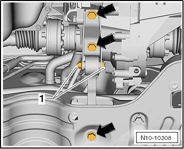
– Unscrew bolts -arrows- for gearbox mounting.
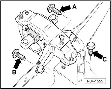
– Unscrew bolts -arrows A, B and C-, and remove gearbox mounting. Installing Install in reverse order of removal, observing the following:
Note
Protected by copyright. Copying for private or commercial purposes, in part or in whole, is not permitted unless authorised by SEAT S.A. SEAT S.A does not guarantee or accept any liability with respect to the correctness of information in this document. Copyright by SEAT S.A.
– Install battery tray ⇒ Electrical system; Rep. gr. 27 ; Battery; Removing and installing battery . Install battery ⇒ Electrical system; Rep. gr. 27 ; Battery; Remov‐ing and installing battery . – Remove support bracket. Specified torques ♦ Gearbox mounting - specified torque and tightening sequence ⇒ “2.1.3 Assembly overview - assembly mountings, Toledo 2013, Ibiza 2016”, page 72
2.4 Removing and installing pendulum sup‐port
⇒ “2.4.1 Removing and positioning pendulum support, Ateca, Leon 2013”, page 84 ⇒ “2.4.2 Removing and installing pendulum support, Ibiza 2018, Arona”, page 85 ⇒ “2.4.3 Pendulum support - removing and installing, Toledo 2013, Ibiza 2016”, page 86
Special tools and workshop equipment required ♦ Torque wrench - V.A.G 1331-
♦ Torque wrench - V.A.G 1332-
Removing – Remove noise insulation ⇒ General body repairs, exterior; Rep. gr. 66 ; Noise insulation; Removing and installing noise insulation component . – Unscrew bolts -1, 2 and 3-, and remove pendulum support. Installing Install in reverse order of removal, observing the following:
Note
Protected by copyright. Copying for private or commercial purposes, in part or in whole, is not permitted unless authorised by SEAT S.A. SEAT S.A does not guarantee or accept any liability with respect to the correctness of information in this document. Copyright by SEAT S.A.
– Bolt pendulum support first to gearbox and then to subframe.
Note
– Install noise insulation ⇒ General body repairs, exterior; Rep. gr. 66 ; Noise insulation; Assembly overview – noise insula‐tion .
Specified torques ♦ ⇒ “2.1.1 Assembly overview - assembly mountings, Ateca, Leon 2013”, page 67
Special tools and workshop equipment required ♦ Torque wrench - V.A.G 1332-
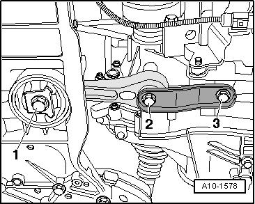
Removing – Unscrew bolts -2-, -3- and -4- of pendulum support -1-. – Pull out pendulum support -1- from subframe. Installing Install in reverse order of removal, observing the following:
Note
– Bolt pendulum support first to gearbox and then to subframe.
Protected by copyright. Copying for private or commercial purposes, in part or in whole, is not permitted unless authorised by SEAT S.A. SEAT S.A does not guarantee or accept any liability with respect to the correctness of information in this document. Copyright by SEAT S.A.
Note
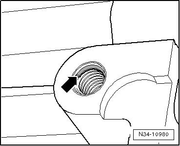
♦ There are threaded holes, e.g. “Heli coil” in the bolting holes for the pendulum support. ♦ The shoulder on the first thread pitch -arrow- is an identifying feature.
Specified torques ♦ ⇒ “2.1.2 Assembly overview - assembly mountings, Ibiza 2018, Arona”, page 70
Special tools and workshop equipment required ♦ Torque wrench - V.A.G 1332-
Removing – If necessary, remove noise insulation. ⇒ General body re‐pairs, exterior; Rep. gr. 50 ; Underbody protection; assembly overview - underbody protection , Toledo ⇒ General body re‐pairs, exterior; Rep. gr. 50 ; Body front; assembly overview noise insulation .
• The threaded connection -1- must not be loosened.
– Unscrew bolts -arrow- and remove pendulum support. Installing Install in reverse order of removal, observing the following:
Note
Protected by copyright. Copying for private or commercial purposes, in part or in whole, is not permitted unless authorised by SEAT S.A. SEAT S.A does not guarantee or accept any liability with respect to the correctness of information in this document. Copyright by SEAT S.A.– Bolt pendulum support first to gearbox and then to subframe. Specified torques ♦ ⇒ “2.1.3 Assembly overview - assembly mountings, Toledo 2013, Ibiza 2016”, page 72
2.5 Supporting engine in installation posi‐tion
⇒ “2.5.1 Supporting engine in installation position, Ateca”, page 87 ⇒ “2.5.2 Supporting engine in installation position, Leon 2013”, page 91 ⇒ “2.5.3 Supporting engine in installation position, Ibiza 2018”, page 93 ⇒ “2.5.4 Supporting engine in installation position, Arona”, page 97 ⇒ “2.5.5 Supporting engine in installation position, Ibiza 2016”, page 102 ⇒ “2.5.6 Supporting engine in installation position, Toledo 2013”, page 103
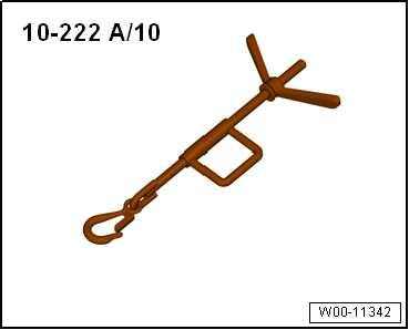
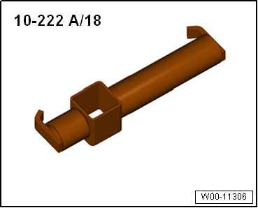
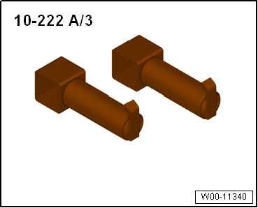
Special tools and workshop equipment required ♦ Support bracket - 10 - 222 A-
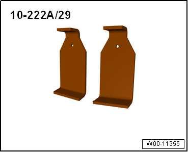
♦ Adapter - 10-222A/29-
Protected by copyright. Copying for private or commercial purposes, in part or in whole, is not permitted unless authorised by SEAT S.A. SEAT S.A does not guarantee or accept any liability with respect to the correctness of information in this document. Copyright by SEAT S.A.
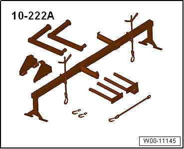
♦ Spindle - 10 - 222 A /10-
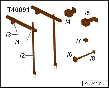
♦ Engine support basic set - T40091-
Protected by copyright. Copying for private or commercial purposes, in part or in whole, is not permitted unless authorised by SEAT S.A. SEAT S.A does not guarantee or accept any liability with respect to the correctness of information in this document. Copyright by SEAT S.A.
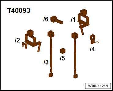
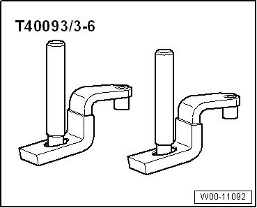
♦ -T40093/6- from engine support supplement set - T40093-
♦ Adapter - T40093/3-6A- (check, and renew if necessary ⇒ page 89 )
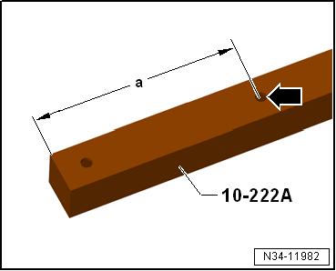
Preparing tools – If adapter -10 - 222 A- does not yet have the hole -arrow-, it must now be drilled into it.
• Dimension -a- = 225 mm.
• Hole diam. = 12.5 mm.
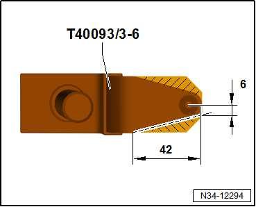
Check adapter - T40093/3-6- and renew if necessary. – Cut out the marked area if necessary. – Round off front edges. – Protect adapter against corrosion. – Then mark the adapter - T40093/3-6- with -T40093/3-6A- . At a later point, support bracket - 10-222 A- will be fitted onto longitudinal members with adapters - T40093/3-6A- . • To prevent damage to the longitudinal members, protect the front part of the adapters - T40093/3-6A- with textile adhesive tape ⇒ Electronic Parts Catalogue (ETKA Chemical Prod‐ucts) . Procedure
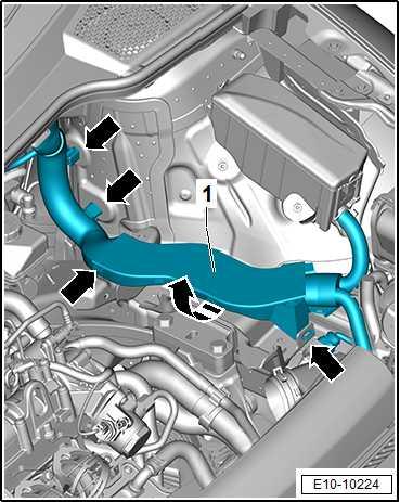
– Remove air filter housing ⇒ “3.2 Removing and installing air filter housing”, page 397 . – Remove air intake pipe ⇒ “2.5 Removing and installing air pipe ”, page 368 .
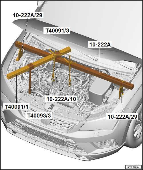
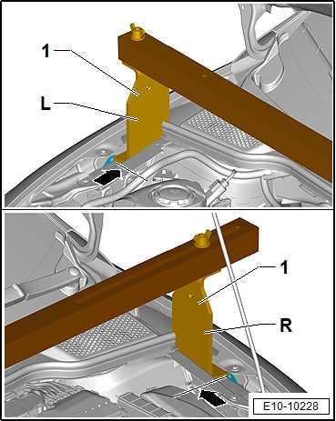
– Bolt adapter - 10 - 222 A /29- labelled »L« to right side of sup‐port bracket - 10-222 A- .
Note
“L” = -1- adapter - 10 - 222 A /29- is to be inserted on right side of vehicle.
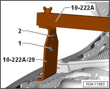
– Slide adapter - T40091/3- onto support bracket - 10 - 222 A- . –Protected by copyright. Copying for private or commercial purposes, in part or in whole, is not permitted unless authorised by SEAT S.A. SEAT S.A does not guarantee or accept any liability with respect to the correctness of information in this document. Copyright by SEAT S.A. Bolt adapter - 10 - 222 A /29- labelled »R« to left side of support bracket - 10-222 A- .
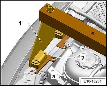
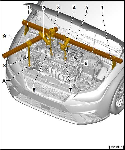
– Fit support bracket - 10 - 222 A- with adapters - 10 - 222 A / 29- onto upper wheel housing longitudinal member, as shown in illustration.
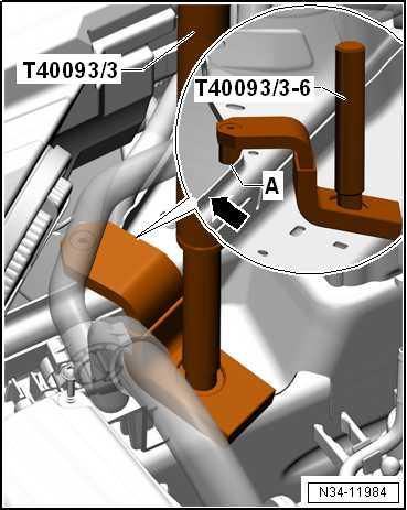
– Place the adapter - T40093/3-6- over the right longitudinal member.
– Bolt -A- must remain behind the rim -arrow-.
– Screw in spindle - T40093 /3- in the pins -A-.
Protected by copyright. Copying for private or commercial purposes, in part or in whole, is not permitted unless authorised by SEAT S.A. SEAT S.A does not guarantee or accept any liability with respect to the correctness of information in this document. Copyright by SEAT S.A.
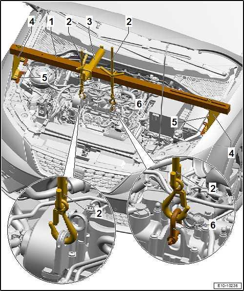
– Connect spindle from engine support supplement set T40093 /3- via square section tube - 10-222 A- to engine support bracket - T40091/1- and tighten. – Attach hook of spindles - 10-222A/10- to engine lifting eyes. – Take up weight of engine/gearbox assembly on spindles, but do not lift it.
Installing Installation is in the reverse sequence of removal. Specified torques ♦ Securing bolts for air filter housing ⇒ “3.1.1 Assembly overview - air filter housing, Ateca, Leon 2013”, page 393
Special tools and workshop equipment required ♦ Support bracket - 10 - 222 A-
♦ Adapter - 10-222A/13-
♦ Spindle - 10 - 222 A /10-
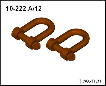
♦ Shackle - 10 - 222 A /12-
Protected by copyright. Copying for private or commercial purposes, in part or in whole, is not permitted unless authorised by SEAT S.A. SEAT S.A does not guarantee or accept any liability with respect to the correctness of information in this document. Copyright by SEAT S.A.
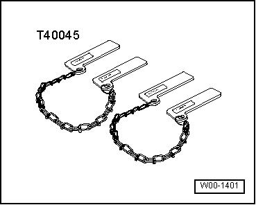
♦ Gauge - T40045-
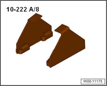
To prevent damage to edges of wings, cover lower areas of both adapters - 10 - 222 A /8- with woven adhesive tape -arrow- ⇒ Electronic Parts Catalogue (ETKA) . Procedure
– Remove air filter housing ⇒ “3.2 Removing and installing air filter housing”, page 397 . – Remove air intake pipe ⇒ “2.5 Removing and installing air pipe ”, page 368 .
• Insert and align the gauges - T40045- -2- as shown in the il‐lustration in the front longitudinal members right and left. When doing so, observe the height -a-. • Attach the adapter - 10 - 222 A /8- -1- on left and right onto longitudinal members as shown in illustration.

– Insert the spindle - 10 - 222 A /10- -5- and adapter - 10 - 222 A /18- -3- into the support bracket - 10 - 222 A- . – Screw in the adapter - 10 - 222 A /8- -4- into the engine inter‐ception device - 10-222 A- -1-. Protected by copyright. Copying for private or commercial purposes, in part or in whole, is not permitted unless authorised by SEAT S.A. SEAT S.A does not guarantee or accept any liability with– Insert the carrying device - 10 - 222 A- -1- and the adapter respect to the correctness of information in this document. Copyright by SEAT S.A.10 - 222 A /8- -4- on left and right onto longitudinal members as shown.
Observe the position and setting of the gauge - T40045- -5⇒ page 92 . – Fit the shackle - 10 - 222 A /12- -6- in the left lifting eye of the engine. – Suspend the karabiners of the spindles - 10 - 222 A /10- -2into the right lifting eye of the engine and suspend the left shackle - 10 - 222 A /12- -6-.
– Tighten spindle to take up weight of engine/gearbox assembly; do not lift.
Special tools and workshop equipment required ♦ Support bracket - 10 - 222 A-
♦ Adapter - 10 222A/29-
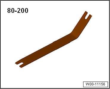
♦ Removal lever - 80 - 200-
Protected by copyright. Copying for private or commercial purposes, in part or in whole, is not permitted unless authorised by SEAT S.A. SEAT S.A does not guarantee or accept any liability with respect to the correctness of information in this document. Copyright by SEAT S.A.
♦ Hook - 10 222A/10-
♦ Adapter - 10 - 222 A /18-
♦ Adapter - 10 222A/3-
♦ Shackle - 10 - 222 A /12-
Protected by copyright. Copying for private or commercial purposes, in part or in whole, is not permitted unless authorised by SEAT S.A. SEAT S.A does not guarantee or accept any liability with respect to the correctness of information in this document. Copyright by SEAT S.A.
♦ Engine support basic set - T40091-
♦ -T40093/6- from engine support supplement set - T40093-
♦ Adapter - T40093/3-6A-
Check adapters - 10 - 222 A /4- and modify as necessary – If adapter -10 - 222 A- does not yet have the hole -arrow-, it must now be drilled into it.
• Dimension -a- = 225 mm.
• Hole diam. = 12.5 mm.
Check adapters - T40093/3-6- and modify as necessary – If necessary, cut off the marked area. – Round off front edges. – Protect adapter against corrosion. – Then, mark adapters - T40093/3-6- as -T40093/3-6A- . At a later point, support bracket - 10-222 A- will be fitted onto longitudinal members with adapters - T40093/3-6A- .
Protected by copyright. Copying for private or commercial purposes, in part or in whole, is not permitted unless authorised by SEAT S.A. SEAT S.A does not guarantee or accept any liability with respect to the correctness of information in this document. Copyright by SEAT S.A.

Procedure
– Remove air filter housing ⇒ “3.2 Removing and installing air filter housing”, page 397 . – Remove air intake pipe ⇒ “2.5 Removing and installing air pipe ”, page 368 . – Remove the filler piece -1- on both sides with the removal lever - 80 200- -2-.
– Slide adapter - 10 - 222 A /3- -4- and adapter - T40091/3- -3over the support bracket - 10 - 222 A- -5-. – Secure support bracket - 10-222 A- -5- to adapters - 10 - 222 A /29- -1-.
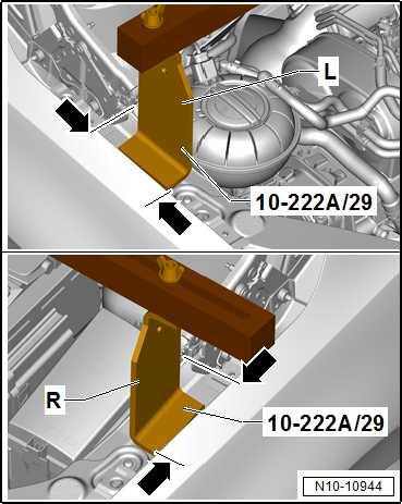
♦ Installation position: Attach the adapter - 10 - 222 A /29- on both sides of the vehicle between the edge of the wing bolted connections and the underlying plate for bolting the wing. The adapter -L- is connected to the “right” side of the vehicle (the adapter -1- is guided into the wing ,recess, here the dimension -arrow- is selected as an orientation point) The adapter “R” is connected to the “left” side of the vehicle (the adapter -1- is guided into the wing recess, here the dimension -arrow- is selected as an orientation point). – If necessary, carefully unclip any pipes for air conditioning system in front area. Do not disconnect pipe/hose system ⇒ Heating, air conditioning; Rep. gr. 87 ; Refrigerant circuit; System overview - refrigerant circuit .
Protected by copyright. Copying for private or commercial purposes, in part or in whole, is not permitted unless authorised by SEAT S.A. SEAT S.A does not guarantee or accept any liability with respect to the correctness of information in this document. Copyright by SEAT S.A.
– Fit adapter -T40093/3-6A- with support - T40093/3- onto right longitudinal member. • The adapter -T40093/3-6A- clicks into place with the dowel -A- behind the longitudinal member edge -arrow-.
– Bolt the spindle of the engine support supplement set T40093 /3- -8- to the adapter - T40093/3-6- -A-. – Connect spindle of the engine support supplement set T40093 /3- -8- over the square section tube - T40091/1- -9- to the adapter - T40091/3- -3-; first guide the adapter - 10 - 222 A /18- -2- to the square section tube - T40091/1- -9-. – Connect square tube - T40091/1- -9- to the adapter T40091/3- -3-. Adjust and clamp. – Suspend spindles - 10 - 222 A /10- -6- in the engine lifting lugs, on the left side if necessary using the shackle - 10 - 222 A /12-7-.
– Take up weight of engine/gearbox assembly and support bracket on spindles . Specified torques ♦ Securing bolts for air filter housing ⇒ “3.1.2 Assembly overview - air filter housing, Ibiza 2018, Ar‐ona”, page 395 ♦ ⇒ “2.1 Assembly overview - charge air system”, page 363
Protected by copyright. Copying for private or commercial purposes, in part or in whole, is not permitted unless authorised by SEAT S.A. SEAT S.A does not guarantee or accept any liability with respect to the correctness of information in this document. Copyright by SEAT S.A.
2.5.4 Supporting engine in installation posi‐tion, Arona
Special tools and workshop equipment required ♦ Support bracket - 10 - 222 A-
♦ Adapter - 10 222A/8-
♦ Removal lever - 80 - 200-
♦ Hook - 10 222A/10-
Protected by copyright. Copying for private or commercial purposes, in part or in whole, is not permitted unless authorised by SEAT S.A. SEAT S.A does not guarantee or accept any liability with respect to the correctness of information in this document. Copyright by SEAT S.A.
♦ Adapter - 10 222A/3-
♦ Engine support basic set - T40091-
♦ -T40093/6- from engine support supplement set - T40093-
♦ Adapter - T40093/3-6A-
Protected by copyright. Copying for private or commercial purposes, in part or in whole, is not permitted unless authorised by SEAT S.A. SEAT S.A does not guarantee or accept any liability with respect to the correctness of information in this document. Copyright by SEAT S.A. Check adapters - 10 - 222 A /4- and modify as necessary – If adapter -10 - 222 A- does not yet have the hole -arrow-, it must now be drilled into it.
• Dimension -a- = 225 mm.
• Hole diam. = 12.5 mm.


