©eBlue-Dist 2007
CHAPTER THREE
.-
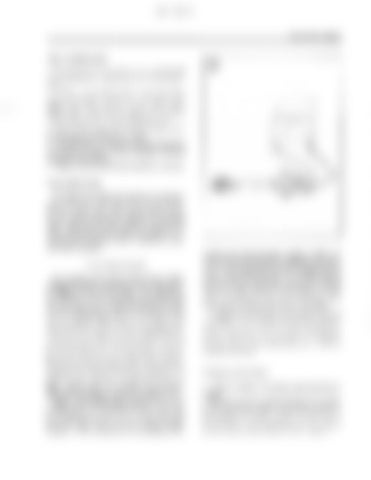
1. Disconnect the neutral switch alid remove it from the power head. Refer to Chapter Seven for the removal procedure. 2. Calibrate the ohmmeter on the R x 1 scale. Connect the positive meter lead to a green lead of the neutral switch (Figmre 33). Connect the negative meter lead to a good engine ground. Test with the shift control lever in FORWARD, NEUTRAL and REVERSE positions. 3. Repeat Step 2 by connecting the positive meter lead to the other green lead of the ~leutralswitch. 4. There should be no continuity- at all times during this test. Replace the neutral switch if continuity is present during any part of the test. 5. Refer to Chapter Seven for the installation procedure.
Manuah Start System The manual start components include the recoil pulley, spring, drive pawls, drive pawl spring, rope and handle. The most colnmon failure of the system is a frayed or broken rope. Before replacing an apparent locked manual starter, verify that the gearcase and power head are not seized and that the starting lockout mechanism is h n c tioning properly. Otherwise, refer to Chapter Ten for complete repair procedures.
CHARGING SYSTEM The charging system consists of the flywheel, battery charging coil (Figure 34 and Figure 351, rectifierlregulator (Figure 361, wires and :he battery. The charging system maintains the battery charge after starting the engine and when using onboard accessories. The use of accessories, such as depth finders, stereos and fish finders, place additionai demands on the charging system, and in some cases, the charging system cannot meet the additional demand leading to a discharged battery. Check all charging system components if the battery discharges. Determine the total amperage of the onboard accessories and compare the total with the charging system output. Remember that the charging system output will be less than the listed maximum if the outboard is consistently operated at low speed. Consider installing an additional battery or a higher capacity battery as a possible solution. Battery maintenance and testing are provided in Chapter Seven. Engines with a manual starter generally do not use a charging system. Some models have the option of a lighting coil. The lighting coil is positioned under the flywheel and produces alternating current as the flywheel magnets rotate past it. The current produced by the lighting coil is
suitable only for operating lights. Adding a rectifier converts the current produced by the lighting coil to direct cuwent. This arrangement allows the cranking battery to charge. Models with electric start use a rectifierlregulator unit. The rectifier portion of this component converts the alternating current produced by the alternator to direct current. The regulator portion of this component senses the voltage at the battery and prevents overcharging. Troubleshooting the charging system requires the use of a multimeter. Use an analog multimeter when checking for open or closed circuits. To begin the troubleshooting process, verify that the charging system is not operating. Test the charging system components after verifying a charging system fault.
Charging System Output 1. Connect a voltmeter to the battery and note the battery voltage. 2. Start the engine and note the voltmeter. If the charging system is functioning, battery voltage will increase over that checked with the engine stopped. A voltage equal to or less than the first measurement indicates that a charging system is not functioning; further testing is required.


