9 minute read
Ignition system testing


5. Replace the stop button and harness (tiller model only) if readings are incorrect. 6. Test the key switch and lanyard switch (remote control models) if either test in Step 3 or Step 4 fails. Refer to Chapter Seven for key switch and lanyard switch testing. 7. Repair or replace the harness (remote control models) connecting the controls to the engine if the key switch and lanyard switch function properly. 8. Perform Steps 3 and 4 to verify proper operation be- fore running the engine. Reconnect all leads and operate the engine to verify proper switch operation. Replace the CDI unit if all other components operate properly, but the engine has no ignition or cannot be stopped.
Spark Plug Cap
Aproblem with the spark plug cap can cause an ignition misfire. Often very humid conditions contribute to the misfire. Replace the spark plug cap if external arcing is noted at the spark plug connection. Corrosion at the con- nections can cause high resistance and result in an ignition misfire. Visually inspect all spark plug caps. Replace any cap that is corroded, cracked or has breaks in the insulat- ing material. The spark plug caps covered in this manual all screw on and off the secondary lead. To remove the spark plug cap. turn it counterclockwise; to install the spark plug cap, turn it clockwise.
Ignition Coil
A problem with an ignition coil can cause or contribute to an intermittent or constant ignition misfire. Perform a visual inspection on all ignition coils. Replace any coil that has corroded terminals or cracks on its body. A coil resistance test can be performed for all models. Coil re- moval and installation procedures are provided in Chapter Seven.
Primary resistance
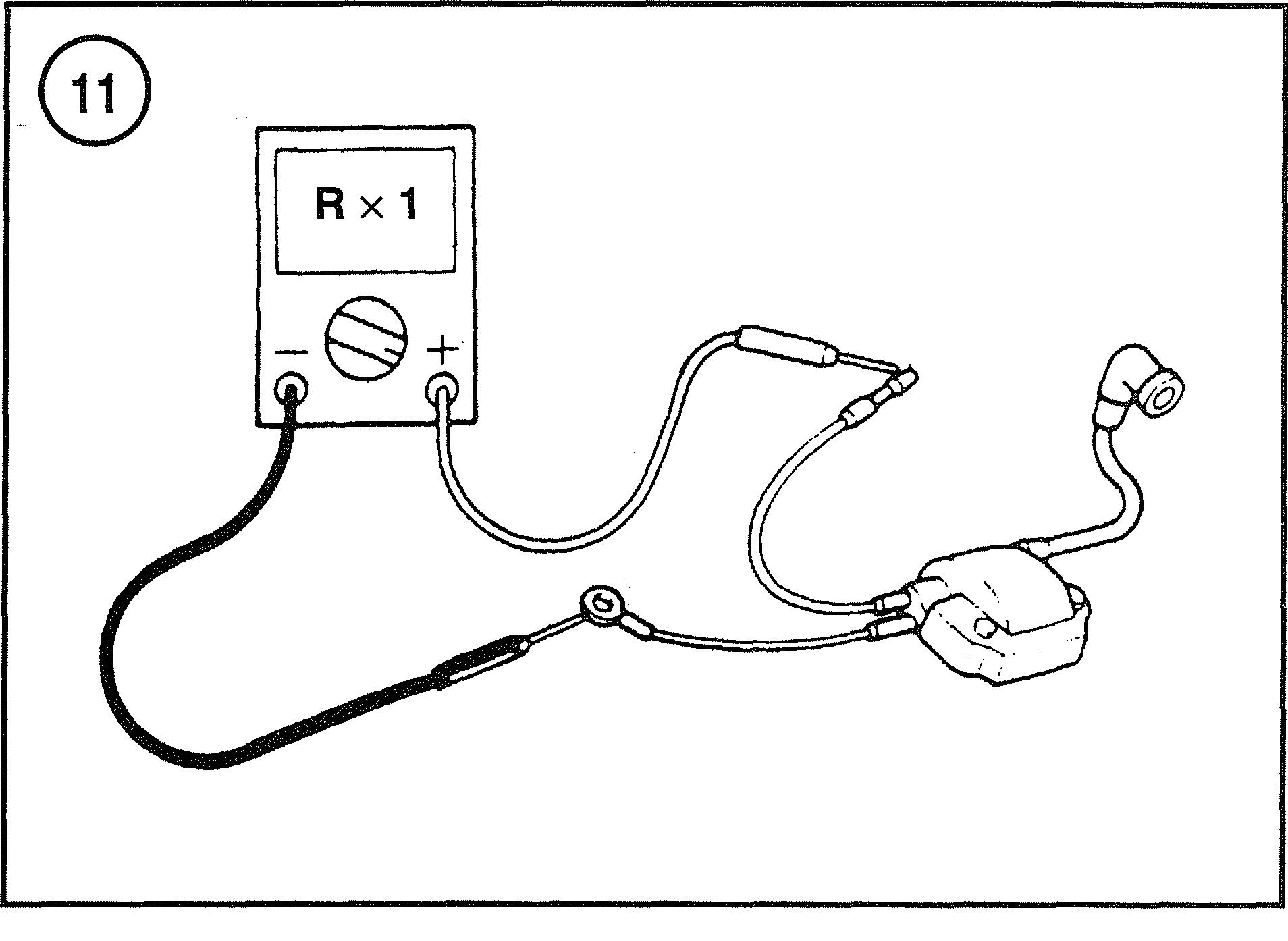
1. Disconnect the primary leads and the secondary lead from the ignition coil. 2. Connect the negative lead of the ohmmeter to the black lead (Figure 11) of the ignition coil. 3. Connect the positive lead of the ohmmeter to the blacldwhite lead (Figure 11) of the ignition coil. 4. Compare the reading with primary resistance specifi- cation at the end of Chapter Seven. 5. Repeat the test for all ignition coils on the engine. Re- place any coil that does not meet the indicated specification. 1. Disconnect the primary leads and secondary lead from the ignition coil. 2. Connect the negative lead of the ohmmeter to the black lead (Figure 12) of the ignition coil. 3. Connect the positive lead of the ohmmeter to the sec- ondary lead (Figure 12) of the ignition coil. 4. Coinpare the reading with the secondary resistance specification in the tables at the end of Chapter Seven. 5. Repeat the test for all ignition coils on the engine. 6. Install the coil onto the power head and connect the leads to proper location.
Pulser Coil
The pulser coil is located under the flywheel. An elec- trical pulse is created as magnets attached to the flywheel pass near the coil. This electrical pulse initiates the spark at the plug. If a pulser coil is faulty, the flywheel (Figure 13) must be removed to access the coil. Flywheel removal


Secondary resistance


is not necessary to access the pulse coil leads. A faulty pulser coil can cause an intermittent or constant ignition misfire. Follow the test procedures carefully to avoid misdiagnosis and unnecessary flywheel removal. Refer to Tables 2-24 in Chapter Seven for the pulser coil specifica- tions. A peak-reading voltmeter is needed to test peak voltage on all models.
Pulser coil resistance
1. Disconnect the pulser coil leads from the harness. 2. Connect the positive and negative ohmmeter leads (Figure 13) to the correct color leads as indicated in the wiring diagrams at the end of this manual.
NOTE Pulser coil resistance test reszdts are not af - fected by polarity of the test leads.
4. Compare the pdser coil resistance with the specification provided in Tables 2-24 in Chapter Seven. Replace the pulser coil if the resistance is not with specification. Removal and installation of the pulser coil are provided in Chapter Seven. 5. Attach the leads to the proper location(s) when testing is complete.
Pulser coilpeak voltage output
When performing this test, all leads must be connected into the main engine harness. Using a test harness or prob- ing the wire connections (Figure 14) allows voltage test- ing while sunning the engine. This test will identify a faulty pulser coil or CDI unit during running conditions.
WARNING Stay clear of the propeller shaft while run- ning an engine on aJlush/test device. As a safety precaution, remove the propeller be- fore performing the test.
1. Connect a peak-reading voltmeter to the pulser coil wires. Refer to the appropriate table at the end of this chapter for the wire colors. 2. Run the engine on a suitable testlflush device or in a test tank. Record the voltage output at the indicated en- gine speed. See Tables 2-24 in Chapter Seven.
NOTE If the peak voltage reading is excessively low, reverse the meter test leads and run the test again before determining the test re- sults.
3. Compare the output with the specification listed in Ta- bles 2-24 at the end of Chater Seven. Replace the CDI unit if the voltage reading is above the specification. Replace the pulser coil if the reading is below the specification. CDI unit and pulser coil replacement are provided in Chapter Seven. 4. Remove the test harness and attach all leads to the proper locations.
CA UTION Never run an ot~tboard without providing cooling water; use either a test tank or jlush/test device. Install a test propeller to run the engine in a test tank.
Ignition Exciter Coil
The ignition exciter coil powers the ignition syslen:. Current is gc~lerated in the coil as magnets attached to the fljw7heel rotate past the coil. This cuxerxt is directed to the CDI unit n-here it is stored for use to create ignition. A faulty ignition exciter coil can cause a.n internittent mis- fire or no spark. 011 certain ~nodcls, the engine may oper- ate properly at one speed and misfire at another speed di~e to a faulty exciter coil. Perform the test caref~dly, as the flywheel must be re~noved to remove the exciter coil. The flywheel does not have to be removed during testing siiicc the coil leads are accessible. Adigital a ineter is required for peak voltage resistailce tests.
Resistance speciiicatioils and peak voltage readings are provided in Chapter Seven. Perform both tests to ensure accurate lest results.
Ig~zibion ex~iter cod reskta~lnce
1. Disconnect all ignition exciter coil le ds from the en-
gine harness. 2. Connect the ineter test leads to the exciter coil leads (Figure 15) as indicated. in Tables 1-24. Chapter Sever;. 3. Compare the resistame xvi'l-l-i the specificatioil listed ig Tables 2-24 ill Chapter Seven, Replace the ignition ex- citer coil if it is not within the specification. Refer to Chapter Seven for re~:~ovai and installation. 4. Connect all Izads to the proper locetinn.
Igfiition exciter coil peak voltage out~uf
When performing this test: all leads must be connected to the engine har~iess. Using a test haness or probiag "I.e wire co~~nectioiis (Figure 14) al!owi the voltage to he tested while the engine is runl~ing. This test call identify a faulty ignition exci;er coii during rumling co~iditions.
JK4 Pu~~>t;PrG
Staj. clear of tfw propell~r slzq? uizile r.zrn- ning an eizgir:e olz a jlzlsh/teLrt ,?'e~*ice, Remove the propeller before ix~zrrirzg flzc eizgine or. pe~fonnir7g a test.
1. Connect a peak-reading boilmeter to the pulses col! wires. Refer to the appropriate table at the elid of Chapter Seven for the wire co!ors.
CA UTIGN iv'ever. rz1n aiz outL~oaid ~t'itizo~~t p~o-oviding cooling water; use either a test tank or Jz~sh/test device. 1;qstall a test propeller. to rzin the engine in a te.rt tank, 4. Remove the test h proper locations.


direct sparl: to rke
TROUBLESHOOTING AKD TESTTTaG - - .- .--------
43


gecerated and stored jrr a capacitor in the CD1 unit. Elec- trical pulses ge!leraied by the pulser coil trigger the re- leas:: of the stored cui-rent, which is directed to the ignition coil. ignition coi? amplifies the current to the voltage needed to jump the gap at the spark plug.
Tile ignition ~irning is advagced at higher engine speeds to improve engine performance and efficiency. On some models, tl-iis is accompiishrd by rotating the pulser coil in relationship to the triggering magnets in the flywheel. 811 other niodels. the CDI unit advances the tinling. Auto- matic spark advance is provided with increased engine speed.
The CDT unit on some models performs other important functions in addition to ignition control. 011 some models the CDI unit limits the engine speed if it receives an ab- normai reading from the overheat sensor, water pressure sensor, or oil level se~sor. All three- and four-cylinder models have a special feahire of the CDI unit for overspeed limitation. There is a third type of speed limita- tion used on the 115, 120 and 140 hp rnodels. The CDI unit iimits the top engine speed to about 1500 rpm if it does not receive a signal from the remote control box through the red/yeliow lead. Testing procedures for these sensors are covered in this cl~apter. Timing and linkage adjustnlents f~r a:I i?~odels are provided in C1ia.pter Five. A peak-reading 1,oltmeter (Model M-530 or equivalent) is required to test peak voltage on all models.
CDP Unit Peak Voltage Test
'#her: perfornning this test, all leads must be connected to the engine harness. The use of a test harness or probing wire connections (Figure 14) allows voltage testing while running the engine. This test can identify a faulty CDI unit å running conditions.
WA RVING Stay clear. ofthe propeller. slzaj? wlzile run- ning an engine on a Jltlslz/test device. Re- nzove tlze propeller before ruiztzi~zg the engine or testing.
1. If necessary, attach a test harness to the engine wiring harness at the CDX unit connector. Connect a peak-reading voltmeter to the 6191 unit wires specified in the appropri- ate table in Chapter Seven.
CA UTION 1Ve13er ratin an outb0ar.d ~vithoutfirst yrovid- ii7g coolirzg wafer: Use either a test tank or Jlus/z/test device. Ren~ove the propeller be-