8 minute read
Starting system


TROUBLESHOOTING AND TESTING
45
LCD MULTIMETER AND OIL LEVEL SENSOR


AND DRIVE (TYPICAL)
1. Lower oil level indicator 2. Float 3. Sensor switch 4. Upper oil level indicator 5. Float 6. Sensor switch
5C. 40 and 50 hp with remote control-The warning horn should sound and the low oil indicator on the tachometer should illuminate when the float contacts the sensor switch. 5D. 40 and 50 hp with tiller handle-when the float con- tacts the sensor switch, the pilot lamp on the lower engine cowl should illuminate. 6. Reinstall the oil level sensor by reversing the removal procedure. Apply RTV sealant to the sensor cap during in- stallation.
STARTING SYSTEM
The starting system may be either manual or electric start. Manual start is offered on 2.5-18 hp models. Both systems are available on 25-50 hp models. The 70-140 hp models use only electric start.
The common components of the electric starting system include the battery, start button or ignition switch, starter solenoid, starter motor, neutral switch and wires.
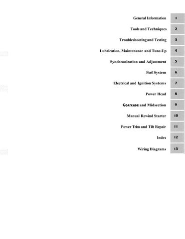
The electric starter motor (Figure 19) is similar in de- sign to what is commonly used on automotive applica- tions. Its mounting position on the power head allows the starter drive gear (Figure 19) to engage a fly- wheel-mounted ring gear when the starter is operated. The
START CIRCUIT

1, Key switch or start button
2. Neutral switch 7 3, Starter solensid 4. Battery connection to solenoid 5. Cable connection to starter motor 6. Ground connections 7. Starter motor
8. Battery
neutral switch prevents the starter motor from operat~ng when the engine is in gear. When the starter is dlseagaged, the flywheel kicks the starter drive do~vn to the starter 1120- tor with the assistance of tile return spring (Figure 19) mounted on the starter drive.
The starter motor is capable of producing a tremendou.s amount of torque, but only for a s1101-t period of rime. A fillly charged battery of sufficient capacity is necessary- to provide the torque required to crank the engine. 8attery re- quirements are 500 niinimm cold-cranking amps, (70 amp hour) and a 105-minute reserve. Weal< or underchxged bat- teries are the leading cause of starting systezn prob!e~ns. Battery maintenance and testillg procedures are provided in Chapter Four.
The operation of the start circuit begins at the igrltion switch or start button When the sw~tch 01 button is oper- ated, current 1s directed to the neutral su~tch (2, Figure 20) and then to starter solenoid (3, Figure 20) The sole- noid is connected to the starter inotor (5, Figure 20) with a large d~ameter cable. When current is supplred to the sole- noid from the neutral swltch, ~t makes an internal connec- tion that allo\vs the current to flom fro111 the batteq directly to the starter inotor Startel motor removal, disas- sembly, inspection, assembly and installation are found in Chapter Seven. Refer to Table 1 for starting system trou-
i I
-7 1 hieshooting. Starting system testing is provided in the fol- hying sections. 3
CA UT10:V Do no: o;~e7-ote the cta~ter n.iotor.for nzore than 10 sei.o~?d.s at n Lfii7ze. Allo~v at least 2 i9zirll~tes hpri:.eeii .i.larfing utien?ptLy ,for. the
stcwter to cool to pi-eve!~l .rliri-ter ~i~otoi- don?- age.


Starter Cranking Voltage Test
This test measures the voltage available at the starter i130tor while craidsing. Make sure the battery is fully charged and in good condition prior to performing this test. See Chapter Se~en. 1. Connect a voltmeter between the starter motor tenni- iial (5: Figure 20) and a good engine ground. 2, Disconnect the spark plug leads and connect them to engine grou-nd. Crank tl:e engine while observing the volt- meter. 3. Repair or replace t?;e starter l~lolor if the voltage is 9.56 volts or greater, but the engine does not crank. 4. Test the starter solenoid and check all starting systein wires for loose or conodzd coilnections if the voltage is less than ?.5 volts. Test the barrely again if all conilections are :i1 goo6. col?dition,
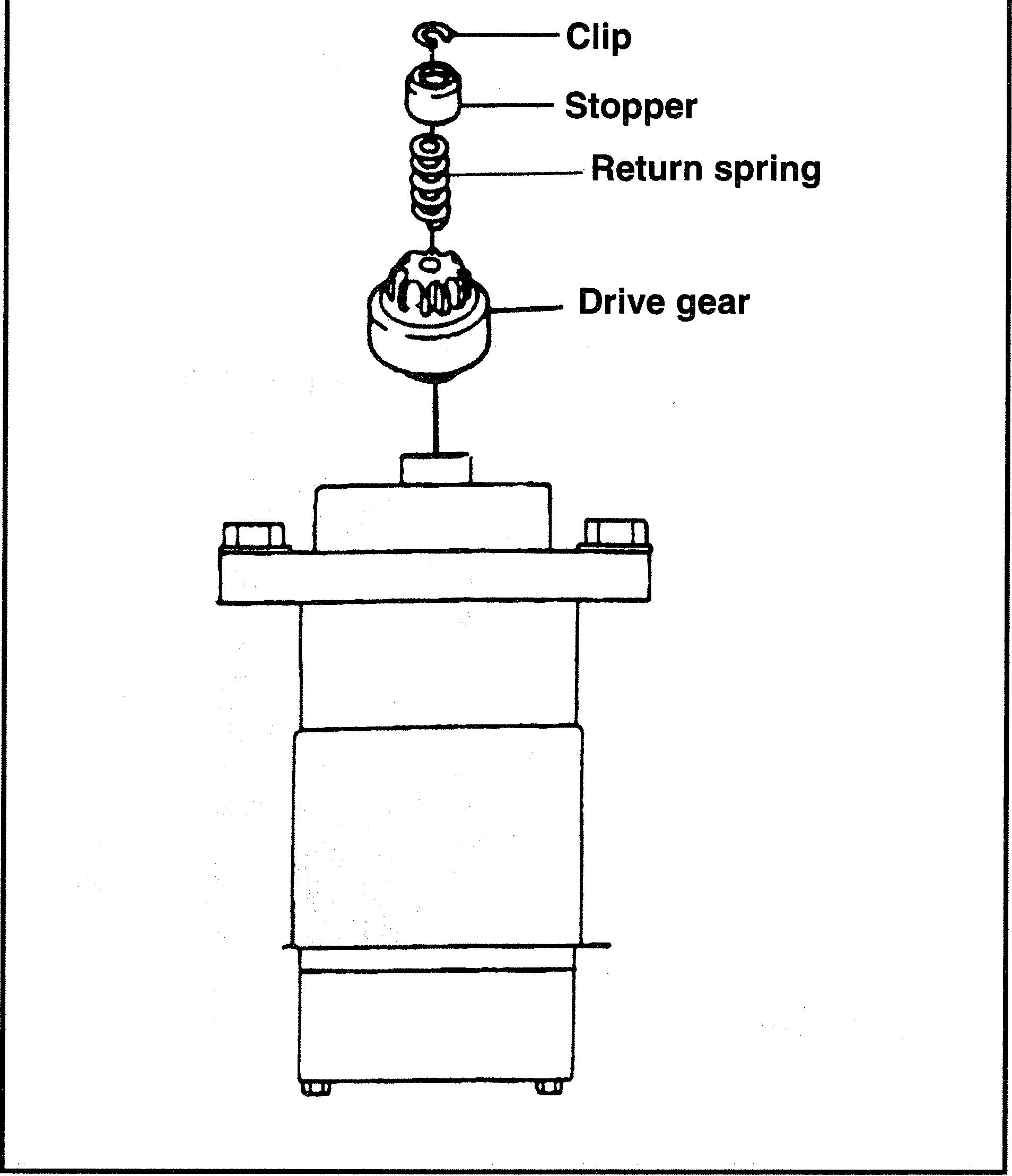
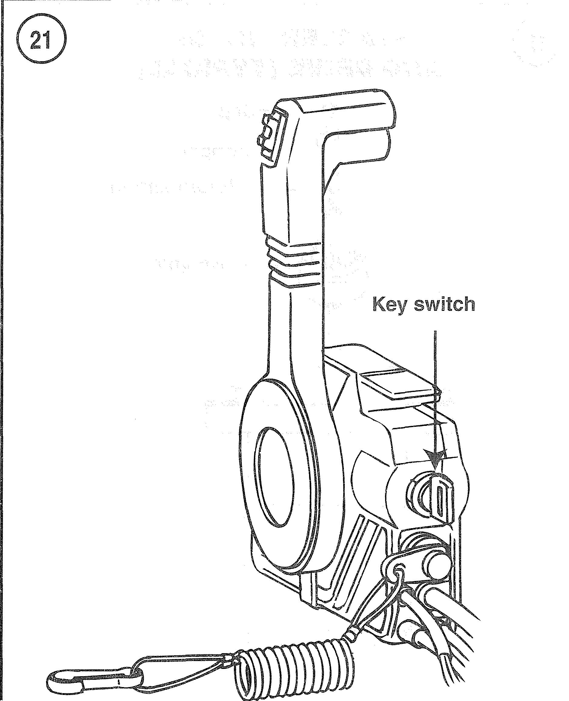
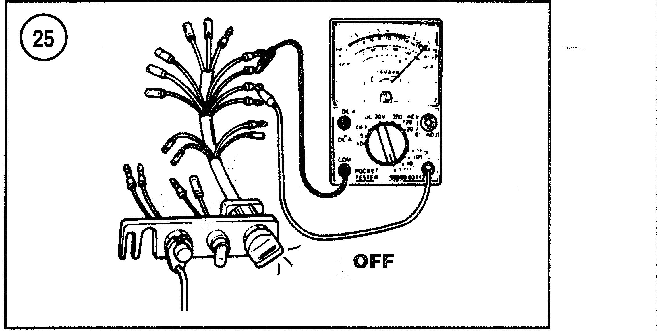
The kniiioiz snitch mounts in either the dash or the re- mote ao~trol Sox (Figure 21) o:! ail ;emote control mod- . . e!s. Check the swltc!~ if the starter does not crank the engine 'out file neritrzl switci~. starter solenoid, coimec- lions, fuses and battery are in good condition. If the inotor is equipped ~t7rtI1 a dash-moun:ed ssvitch, remove the switch and perform Steps 4-7. If the ignition switch is lo- cated in the co~itrol Sox; it is necessary to partially disas- semble the control box to test the switch. Perform Steps ! -7 to test a control box-mounted ignition switch. 1. Remo\e the cuntrol box fro111 its mounting bracket. Rcrnoie the access coyer (Figure 22) from the lower side of the control. 2, Reil~o\.c the back cover scren-s (Figure 23). Remove the key from the s~itcii. Loosen and remove the retainer (6; Figure 24) fro111 the ignition switch. 3. Disconnect the ignition switch from the harness and remove the switch from ~Ele col~troi box. 4. Calibrate ail ohrnnieter on the R x 1 scale. Connect the ohmmeter between the black and brown switch terminals. See Figure 25. Wit11 the switch ir, the OFF position. conti-
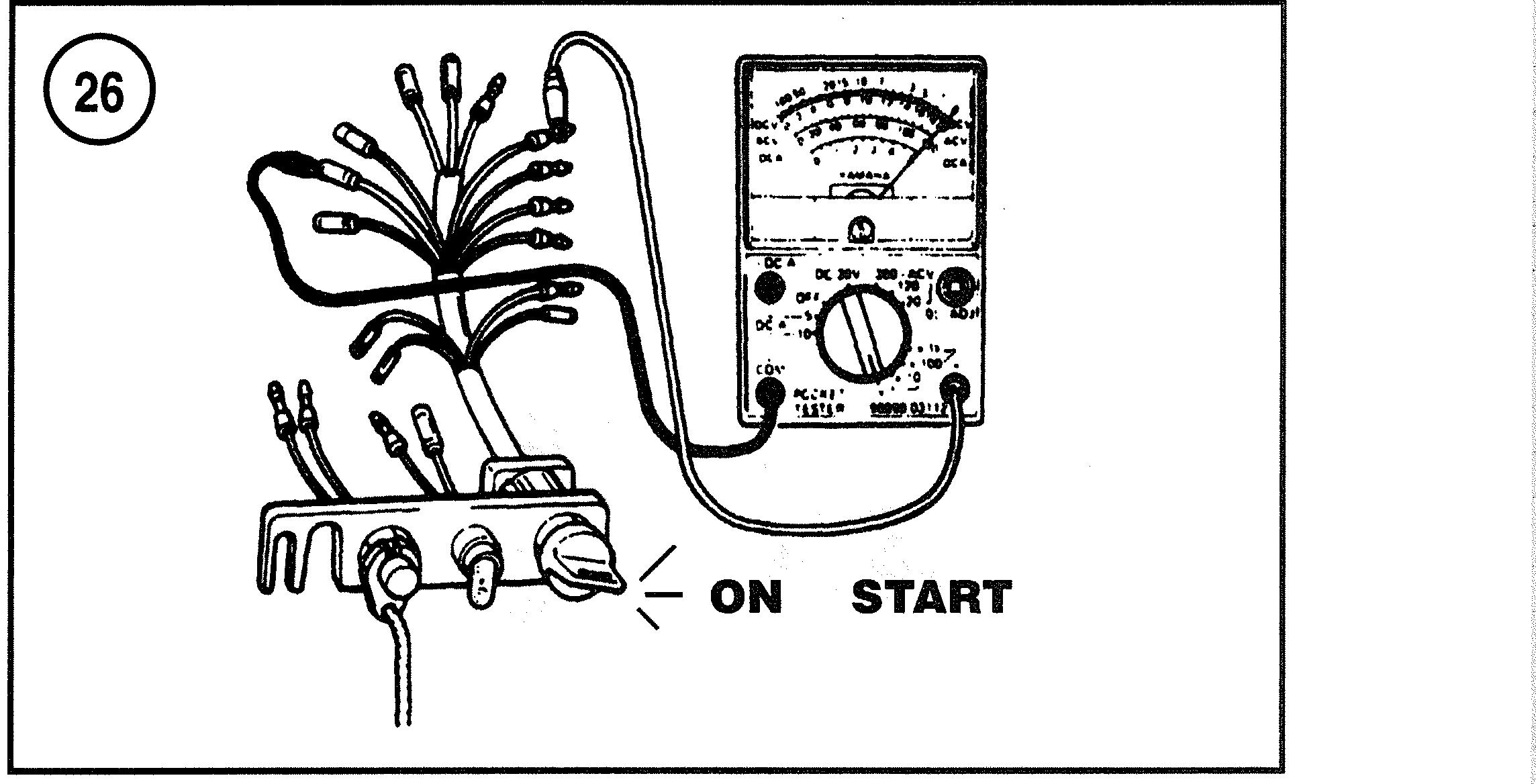
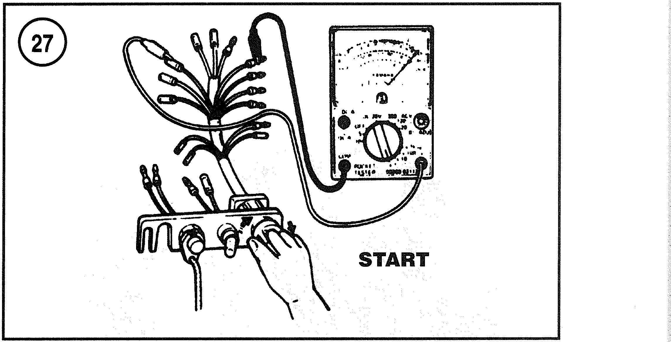
nuity should be noted. Place the switch in the ON posi- tion. No continuity should now be noted. 5. Connect the ohmmeter between the blue and red termi- nals (Figure 26). Continuity should be present with the switch in the ON and START positions. No continuity should be present with the switch in the OFF position. 6. Connect the ohmmeter between the brown and red ter- minals (Figure 27). Continuity should be noted with the switch in the START position. No continuity should be noted with the switch in the OFF and ON positions. 7. Replace the ignition switch if it fails to function as de- scribed.
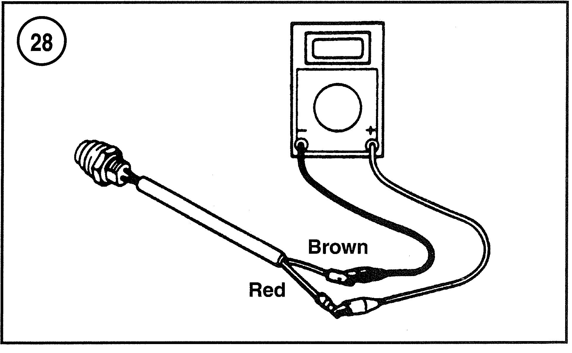
Start Button Test (Tiller Models)
On electric start tiller handle models, the start button (Figure 28) mount to the front of the lower cowl. 1. Disconnect the starter button from the engine wiring harness. Remove the threaded retainer from inside the motor cowl and remove the button. 2. Connect the ohmmeter between the start button wires or terminals. With the button deactivated, the meter should indicate no continuity. 3. With the button activated, the meter should indicate continuity. 4. Replace the start button if it does not function as de- scribed.
Starter Solenoid Test
The starter solenoid allows a large amount of current to pass from the battery to the starter motor. When the start switch or button is operated, current flows through the neutral switch and on to the solenoid. This current passes through a coil of wire in the solenoid. creating a strong magnetic force. The magnetic force moves a plunger that closes contact points in the solenoid, allowing current to flow directly from the battery to the starter motor. 1. Remove the solenoid as described in Chapter Seven. Connect the negative meter test lead to one of the large terminals on the solenoid (Figure 29). Connect the posi- tive meter test lead to the other large terminal connection. The correct reading is no continuity. 2. Us~ng jumper leads, connect the black lead of the sole- noid to the negative terminal of a fully charged battery (Figure 29). Connect a jumper lead to the positive termi- nal of a fully charged battery. While observing the meter, connect the jumper lead to the brown lead of the solenoid (Figure 29). The correct reading is continuity. 3. Replace the solenoid if it does not operate as described.
TROUBLESHOOTING AND TESTING
Neutral Switch Test
The neutral switch is provided to prevent the starter from operating when the engine is in forward or reverse gear. A neutral lockout lever (start-in-gear protection) is provided on 5-40 hp models and a neutral lockout cable is used on 50 hp and larger models with manual start. Repair procedures for these mechanisms are provided in Chapter Ten. Electric start models with tiller handle control are provided with a neutral switch mounted on the engine. Verify proper neutral switch adjustment on tiller models

I
1. Main switch 2. Lanyard switch 3. Choke switch
4. Neutral switch
5. Warning buzzer 6. Key switch retainer 7. Wire connection to harness
I
before testing or replacing the switch. On electric start models with remote control, the switch is located inside the control. Partial disasselnbly of the control is required before testing the switch. An ohmmeter and a ruler are re- quired to perfonn this test.
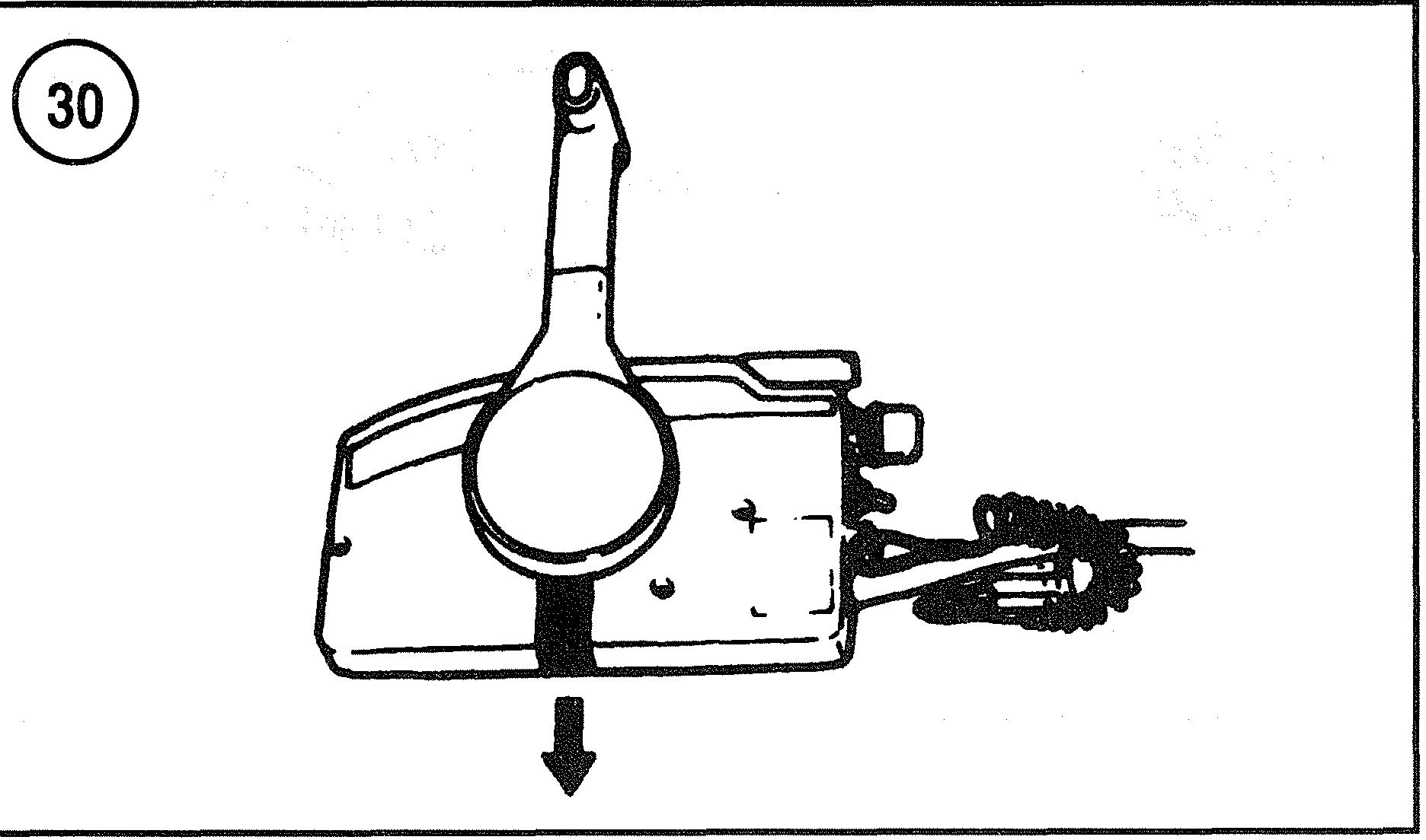
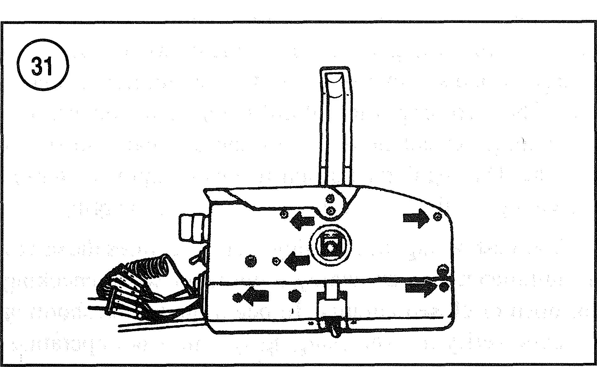
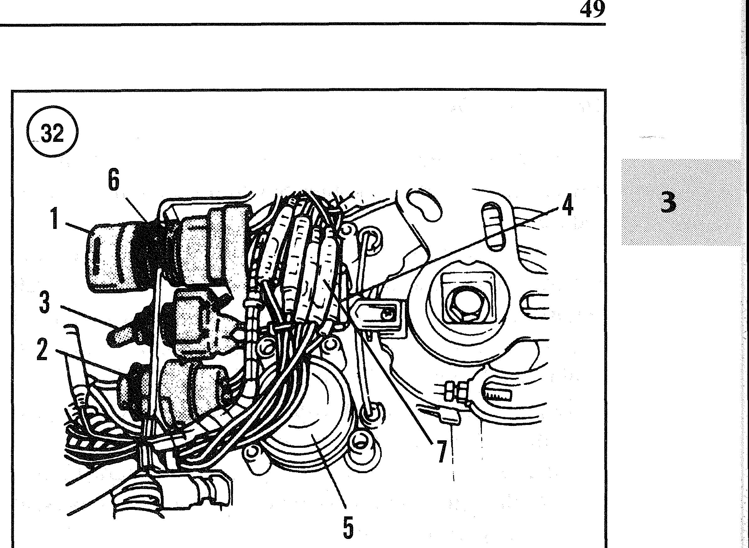
1. Remove the control from its mount. Remove the cover from the lower side of the control (Figure 30). Remove the screws that retain the back cover (Figure 31). Discon- nect the leads and remove the neutral switch (Figure 32). 2. Calibrate an ohmmeter on the R x 1 scale. Connect the positive meter lead to one red lead on the switch. Connect the negative meter lead to an engine ground. Test with the control in FORWARD, NEUTRAL and REVERSE positions. 3. Repeat Step 2, connecting the positive meter lead to the green lead on the neutral switch. 4. Repeat Step 2, connecting the positive meter lead to the other red lead on the neutral switch. 5. There should be no continuity at all times during this test. Replace the neutral switch if continuity is present during any part of the test.