23 minute read
Fasteners .................................. 2 Propellers


Anodes must be used properly to be effective. Simply fastening pieces of zinc to your boat in random locations won't do the job.
You must determine how much anode surface area is required to adequately protect the equip- ment's surface area. A good starting point is provided by Military Specification MIL-A- 8 1800 1, which states that one square inch of new anode will protect either: a. 800 square inches of freshly painted steel. b. 250 square inches of bare steel or bare aluminum alloy. c. 100 square inches of copper or copper alloy.
This rule is for a boat at rest. When underway, more anode area is required to protect the same equipment surface area.
The anode must be fastened so that it has good electrical contact with the metal to be protected. If possible, the anode can be attached directly to the other metal. If that is not possible, the entire network of metal parts in the boat should be electrically bonded together so that all pieces are protected.
Good quality anodes have inserts of some other metal around the fastener holes. Otherwise, the anode could erode away around the fastener. The anode can then become loose or even fall off, removing all protection.
Another Military Specification (MIL-A- 18001) defines the type of alloy preferred that will corrode at a uniform rate without forming a crust that could reduce its efficiency after a time.
Impressed Current Systems
An impressed current system can be installed on any boat that has a battery. The system con- sists of an anode, a control box and a sensor. The anode in this system is coated with a very noble metal, such as platinum, so that it is almost corrosion-free and will last indefinitely. The sen- sor, under the boat's waterline, monitors the po- tential for corrosion. When it senses that corrosion could be occurring, it transmits this information to the control box.
The control box connects the boat's battery to the anode. When the sensor signals the need, the control box applies positive battery voltage to the anode. Current from the battery flows from the anode to all other metal parts of the boat, no matter how noble or non-noble these parts may be. This battery current takes the place of any galvanic current flow.
Only a very small amount of battery current is needed to counteract galvanic corrosion. Manu- facturers estimate that it would take two or three months of constant use to drain a typical marine battery, assuming the battery is never recharged.
An impressed current system is more expen- sive to install than simple anodes but, consider- ing its low maintenance requirements and the excellent protection it provides, the long-term cost may actually be lower.
CHAPTER ONE
PROPELLERS
The propeller is the final link between the boat's drive system and the water. A perfectly
GENERAL INFORMATION
15
maintained engine and hull are useless if the propeller is the wrong type or has been allowed to deteriorate. Although propeller selection for a specific situation is beyond the scope of this book, the following information on propeller construction and design will allow you to discuss the subject intelligently with your marine dealer. How a Propeller Works
As the curved blades of a propeller rotate through the water, a high-pressure area is created on one side of the blade and a low-pressure area exists on the other side of the blade (Figure 18). The propeller moves toward the low-pressure area, carrying the boat with it. Propeller Parts
tip separates the leading edge from the trailing edge. The leading edge is the edge of the blade nearest to the boat. During normal rotation, this is the area of the blade that first cuts through the water. The trailing edge is the edge of the blade farthest from the boat. The blade face is the surface of the blade that faces away from the boat. During normal rota- tion, high pressure exists on this side of the blade. The blade back is the surface of the blade that faces toward the boat. During normal rotation, low pressure exists on this side of the blade. The cup is a small curve or lip on the trailing edge of the blade. The hub is the central portion of the propeller. It connects the blades to the propeller shaft (part of the boat's drive system). On some drive sys- *lthough a propeller may be a 'newpiece unit, tems, engine is routed through the hub; it is made of different Parts Pigure in this case, the hub is up of an outer and 19). Variations in the design of these parts make an inner connected by ribs. different propellers suitable for different jobs. The diffuser ring is used on through-hub ex-
The blade tip is the point on the blade farthest haust models to prevent exhaust gases from en- from the center of the propeller hub. The blade tering the blade area.

16 CHAPTER ONE
Propeller Design
Changes in length, angle. thickness and mate- rial of propeller pans make different propellers suitable for different situations. 2. That is, it is the diameter of the circle formed by the blade tips during propeller rotation (Fig-
ure 20).
Pitch and rake
Diameler Propeller pitch and rake describe the place-
Propeller diameter is the distance from the ment of the blade in relation to the hub (Figure center of the hub to the blade tip, multiplied by 21).


GENERAL INFORMATION
Pitch is expressed by the theoretical distance that the propeller would travel in one revolution. In A, Figure 22, the propeller would travel 10 inches in one revolution. In B, Figure 22, the propeller would travel 20 inches in one revolu- tion. This distance is only theoretical; during actual operation, the propeller achieves about 80% of its rated travel.
Propeller blades can be constructed with con- stant pitch (Figure 23) or progressive pitch (Fig- ure 24). Progressive pitch starts low at the lead- ing edge and increases toward to trailing edge. The propeller pitch specification is the average of the pitch across the entire blade.
Blade rake is specified in degrees and is meas- ured along a line from the center of the hub to the blade tip. A blade that is perpendicular to the hub (A, Figure 25) has 0" of rake. A blade that is angled from perpendicular (B, Figure 25) has a rake expressed by its difference from perpen-


18
dicular. Most propellers have rakes ranging from 0-20". Blade thickness
Blade thickness is not uniform at all points along the blade. For efficiency, blades should be as thin as possible at all points while retaining enough strength to move the boat. Blades tend to be thicker where they meet the hub and thinner at the blade tip (Figure 26). This is to support the heavier loads at the hub section of the blade. This thickness is dependent on the strength of the material used.
When cut along a line from the leading edge to the trailing - edge - in the central portion of the blade (Figure 27). the propeller blide resembles an airplane wing. The blade face, where high pressure exists during normal rotation, is almost flat. The blade back, where low pressure exists during normal rotation, is curved, with the thin- nest portions at the edges and the thickest portion at the center.
Propellers that run only partially submerged, as in racing applications, may have a wedge- shaped cross-section (Figure 28). The leading edge is very thin; the blade thickness increases toward the trailing edge, where it is the thickest. If a propeller such as this is run totally sub- merged, it is very inefficient. Number of blades
The number of blades used on a propeller is a compromise between efficiency and vibration. A one-blade propeller would be the most efficient, but it would also create high levels of vibration. As blades are added, efficiency decreases, but so do vibration levels. Most propellers have three blades, representing the most practical trade-off between efficiency and vibration.
Propeller materials are chosen for strength, corrosion resistance and economy. Stainless steel, aluminum and bronze are the most com- monly used materials. Bronze is quite strong but CHAPTER ONE


GENERAL INFORMATION
8 9
rather expensive. Stainless steel is more common than bronze because of its combination of strength and lower cost. Aluminum alloys are the least expensive but usually lack the strength of steel. Plastic propellers may be used in some low horsepower applications.
Direction of rotation
Propellers are made for both right-hand and left-hand rotation although right-hand is the most commonly used. When seen from behind the boat in forward motion, a right-hand propel- ler turns clockwise and a left-hand propeller turns counterclockwise. Off the boat, you can tell the difference by observing the angle of the blades (Figure 29). A right-hand propeller's blades slant from the upper left to the lower right; a left-hand propeller's blades are the opposite.
Cavitation and Ventilation
Cavitation and ventilation are not inter- changeable terns; they refer to two distinct prob- lems encountered during propeller operation.
To understand cavitation, you must first un- derstand the relationship between pressure and the boiling point of water. At sea level, water will boil at 212" F. As pressure increases, such as within an engine's closed cooling system, the boiling point of water increases-it will boil at some temperature higher than 2 12" F. The oppo- site is also true. As pressure decreases, water will boil at a temperature lower than 212" F. If pres- sure drops low enough, water will boil at typical ambient temperatures of 50-60" F.
We have said that, during normal propeller operation, low-pressure exists on the blade back. Normally, the pressure does not drop low enough for boiling to occur. However, poor blade design

20 CHAPTER ONE
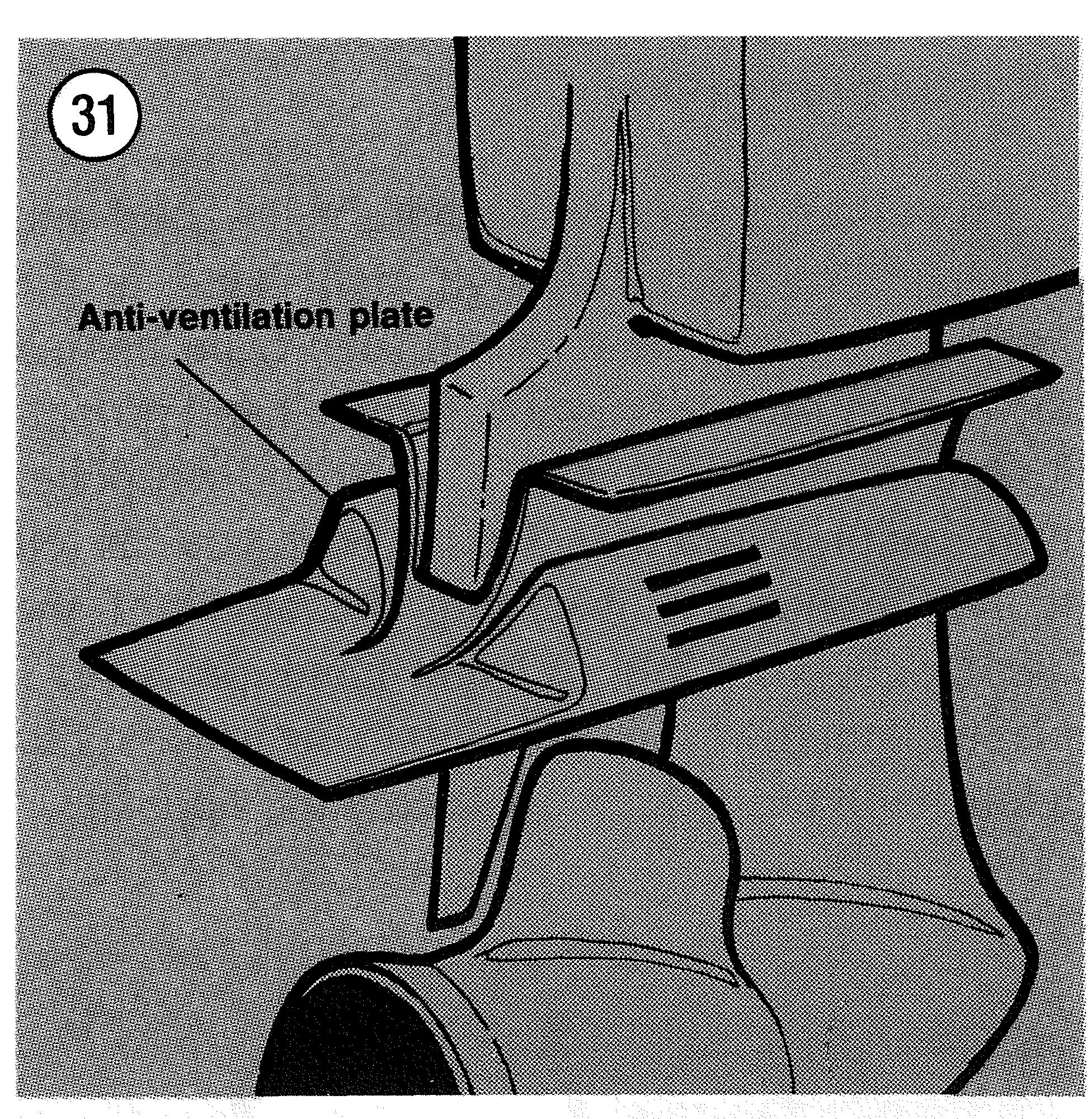
or selection, or blade damage can cause an un- air from entering the blade area (Figure 31). This usual pressure drop on a small area of the blade plate is correctly called an "antiventilation (Figure 30). Boiling can occur in this small area. plate," although you will often see it called an As the water boils, air bubbles form. As the "anticavitation plate." Through hub exhaust sys- boiling water passes to a higher pressure area of tems also have specially designed hubs to keep the blade, the boiling stops and the bubbles col- exhaust gases from entering the blade area. lapse. The collapsing bubbles release enough energy to erode the surface of the blade.
This entire process of pressure drop, boiling and bubble collapse is called "cavitation." The damage caused by the collapsing bubbles is called a "cavi- tation bum." It is important to remember that cavi- tation is caused by a decrease in pressure, not an increase in temperature.
Ventilation is not as complex a process as cavi- tation. Ventilation refers to air entering the blade area, either from above the surface of the water or from a through-hub exhaust system. As the blades meet the air, the propeller momentarily over-revs, losing most of its thrust. An added complication is that as the propeller over-revs, pressure on the blade back decreases and massive cavitation can occur.
Most pieces of marine equipment have a plate above the propeller area designed to keep surface

Chapter Two
Tools and Techniques
This chapter describes the common tools re- quired for marine equipment repairs and trou- bleshooting. Techniques that will make your work easier and more effective are also de- scribed. Some of the procedures in this book require special skills or expertise; in some cases, you are better off entrusting the job to a dealer or qualified specialist.
SAFETY FIRST
Professional mechanics can work for years and never suffer a serious injury. If you follow a few rules of common sense and safety, you too can enjoy many safe hours servicing your marine equipment. If you ignore these rules, you can hurt yourself or damage the equipment. 1. Never use gasoline as a cleaning solvent. 2. Never smoke or use a torch near flammable liquids, such as cleaning solvent. If you are working in your home garage, remember that your home gas appliances have pilot lights. 3. Never smoke or use a torch in an area where batteries are being charged. Highly explosive hydrogen gas is formed during the charging process. 4. Use the proper size wrenches to avoid damage to fasteners and injury to yourself. 5. When loosening a tight or stuck fastener? think of what would happen if the wrench should slip. Protect yourself accordingly. 6. Keep your work area clean, uncluttered and well lighted. 7. Wear safety goggles during all operations involving drilling, grinding or the use of a cold chisel. 8. Never use worn tools. 9. Keep a Coast Guard approved fire extin- guisher handy. Be sure it Is rated for gasoline (Class B) and electrical (Class C) fires.
BASIC HAND TOOLS
A number of tools are required to maintain marine equipment. You may already have some of these tools for home or car repairs. There are also tools made especially for marine equipment repairs; 'these you will have to purchase. In any case, a wide variety of quality tools will make repairs easier and more effective.
Keep your tools clean and in a tool box. Keep them organized with the sockets and related
22
drives together, the open end and box wrenches together, etc. After using a tool, wipe off dirt and grease with a clean cloth and place the tool in its correct place.
The following tools are required to perform virtually any repair job. Each tool is described and the recommended size given for starting a tool collection. Additional tools and some dupli- cations may be added as you become more fa- miliar with the equipment. You may need all standard U.S. size tools, all metric size tools or a mixture of both.
Screwdrivers
The screwdriver is a very basic tool, but if used improperly, it will do more damage than good. The slot on a screw has a definite dimen- sion and shape. A screwdriver must be selected to conform with that shape. Use a small screw- driver for small screws and a large one for large screws or the screw head will be damaged.
Two types of screwdriver are commonly re- quired: a common (flat-blade) screwdriver (Fig- ure I) and Phillips screwdrivers (Figure 2).
Screwdrivers are available in sets, which often include an assortment of common and Phillips blades. If you buy them individually, buy at least the following: a. Common screwdriver-5/16 x 4 in. blade. b. Common screwdriver-318 x 12 in. blade c. Phillips screwdriver-size 2 tip, 6 in. blade.
Use screwdrivers only for driving screws. Never use a screwdriver for prying or chiseling. Do not try to remove a Phillips or Allen head screw with a common screwdriver; you can dam- age the head so that the proper tool will be unable to remove it.
Keep screwdrivers in the proper condition and they will last longer and perform better. Always keep the tip of a common screwdriver in good condition. Figure 3 shows how to grind the tip to the proper shape if it becomes damaged. Note the parallel sides of the tip.
CHAPTER TWO
Pliers
Pliers come in a wide range of types and sizes. Pliers are useful for cutting, bending and crimp- ing. They should never be used to cut hardened objects or to turn bolts or nuts. Figure 4 shows several types of pliers.
Each type of pliers has a specialized function. General purpose pliers are used mainly for hold- ing things and for bending. Locking pliers are used as pliers or to hold objects very tightly, like a vise. Needlenose pliers are used to hold or bend small objects. Adjustable or slip-joint pliers can


TOOLS AND TECHNIQUES

23
be adjusted to hold various sizes of objects; the jaws remain parallel to grip around objects such as pipe or tubing. There are many more types of pliers. The ones described here are the most commonly used.
Box and Open-mmrenrrenches
Box and open-end wrenches are available in sets or separately in a variety of sizes. See Figure 5 and Figure 6. The number stamped near the end refers to the distance between two parallel flats on the hex head bolt or nut.
Box wrenches are usually superior to open- end wrenches. An open-end wrench grips the nut on only two flats. Unless it fits well, it may slip and round off the points on the nut. The box wrench grips all 6 flats. Both 4-point and 12- point openings on box wrenches are available. The 6-point gives superior holding power; the 12-point allows a shorter swing.

24
Combination wrenches, which are open on one side and boxed on the other, are also avail- able. Both ends are the same size.
Adjustable Wrenches
An adjustable wrench can be adjusted to fit nearly any nut or bolt head. See Figure 7. How- ever, it can loosen and slip, causing damage to the nut and maybe to your knuckles. Use an adjustable wrench only when other wrenches are not available.
Adjustable wrenches come in sizes ranging from 4-18 in. overall. A 6 or 8 in. wrench is recommended as an all-purpose wrench.
Socket Wrenches
This type is undoubtedly the fastest, safest and most convenient to use. See Figure 8. Sockets, which attach to a suitable handle, are available with 6-point or 12-point openings and use 114, 318 and 314 inch drives. The drive size indicates
CHAPTER TWO


TOOLS AND TECHNIQUES


2%
the size of the square hole that mates with the ratchet or flex handle.
Torque Wrench
A torque wrench (Figure 9) is used with a socket to measure how tight a nut or bolt is installed. They come in a wide price range and with either 318 or 112 in. square drive. The drive size indicates the size of the square drive that mates with the socket. Purchase one that meas- ures up to 150 ft.-lb. (203 N.m).
Impact Drives
This tool (Figure PO) makes removal of tight fasteners easy and eliminates damage to bolts and screw slots. Impact drivers and interchange- able bits are available at most large hardware and auto parts stores.
Circlip Pliers
Cisclip pliers (sometimes referred to as snap- ring pliers) are necessary to remove circlips, See Figure 81. Circlip pliers usually come with sev- eral different size tips; many designs can be switched from internal type to external type.
Hammers
The correct hammer is necessary for repairs. Use only a hammer with a face (or head) of rubber or plastic or the soft-faced type that is filled with buckshot (Figure 12). These are sometimes necessary in engine tear-downs. Never- use a metal-faced hammer as severe dam- age will result in most cases. You can always produce the same amount of force with a soft- faced hammer.
26
Feeler Gauge
This tool has either flat or wire measuring gauges (Figure 13). Wire gauges are used to measure spark plug gap; flat gauges are used for all other measurements. A non-magnetic (brass) gauge may be specified when working around magnetized parts.
Other Special Tools
Some procedures require special tools; these are identified in the appropriate chapter. Unless otherwise specified, the part number used in this book to identify a special tool is the marine equipment manufacturer's part number*
Special tools can usually be purchased through your marine equipment dealer. Some can be made locally by a machinist, often at a much lower price. "I'ou may find certain special tools at tool rental dealers. Don't use makeshift tools if you can't locate the correct special tool; you will probably cause more damage than good.
TEST EQUIPMENT
Multimeter
This instlument (Figure 14) is invaluable for electrical system troubleshooting anad service. It combines a voltrnetep; an ohmmeter and an am- meter into one unit, so it is often called a VOM.
Two types of multimeter are available, analog and digital. Analog meters have a moving needle with marked bands indicating the volt, ohm and amperage scales. The digital meter (DVOM) is ideally suited for troubleshooting because it is easy to read, more accurate than analog, coi~tains internal overload protection. is auto-ranging (analog meters must be recalibrated each time the scale is changed) and has automatic polarity compensation, CHAPTER TWO


TOOLS AND TECHNIQUES 27


Strobe Timing Light
This instrument is necessary for dynamic tun- ing (setting ignition timing while the engine is running). By flashing a light at the precise instant the spark plug fires, the position of the timing mark can be seen. The flashing light makes a moving mark appear to stand still opposite a stationary mark.
Suitable lights range from inexpensive neon bulb types to powerful xenon strobe lights. See Figure 15. A light with an inductive pickup is best because it eliminates any possible damage to ignition wiring.
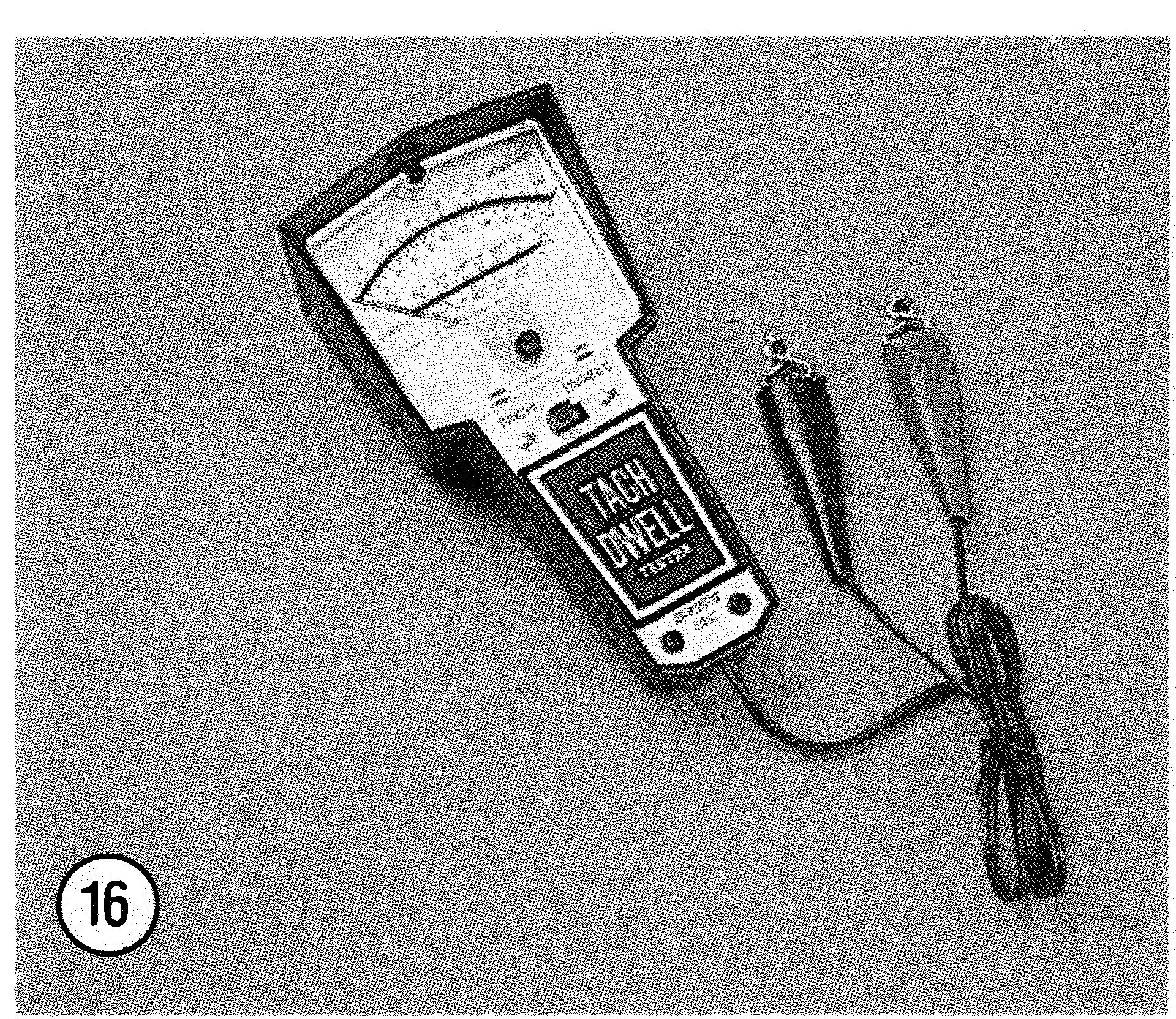
Tachometer/Dwell Meter
A portable tachometer is necessary for tuning. See Figure 16. Ignition timing and carburetor adjustments must be performed at the specified idle speed. The best instrument for this purpose is one with a low range of 0- 1000 or 0-2000 rpm and a high range of 0-6000 rpm. Extended range (0-6000 or 0-8000 rpm) instruments lack accu- racy at lower speeds. The instrument should be capable of detecting changes of 25 rpm on rhe low range.
A dwell meter is often combined with a ta- chometer. Dwell meters are used with breaker point ignition systems to measure the amourat of time the points remain closed during engine operation.
Compression Gauge
This tool (Figure 19) measures the amount of pressure present in the engine's combustion chamber during the compression stroke. This indicates general engine condition. Compression readings can be interpreted along with vacuum gauge readings to pinpoint specific engine me- chanical problems.
The easiest type to use has screw-in adapters that fit into the spark plug holes. Press-in mbber- tipped types are also available.
28
Biacuum Gauge
The vacuum gauge (Figure 18) measures the intake manifold vacuum created by the engine's intake stroke. Manifold and valve problems (on 4-stroke engines) can be identified by interpret- ing the readings. When combined with compres- sion gauge readings, other engine problems can be diagnosed.
Some vacuum gauges can also be used as fuel pressure gauges to trace fuel system problems.
Hydrometer
Battery electrolyte specific gravity is meas- ured with a hydrometer (Figure 19). The specific gravity of the electrolyte indicates the battery's state of charge. The best type has automatic temperature compensation; otherwise, you must calculate the compensation yourself.
Precision Measuring Tools
Various tools are needed to make precision measurements, A dial indicator (Figure EO), for example, is used to determine run-out of rotating parts and end play of pasts assemblies. A dial indicator can also be used to precisely measure piston position in relation to top dead center; some engines require this measurement for igni- tion timing adj ustment.
Vernier calipers (Figure 21) and micrometers (Figure 22) are other precision measuring tools used to determine the size of parts (such as piston diameter).
Precision measuring equipment must be stored, handled and used carefully or it will not remain accurate.
SERVICE HINTS
Most sf the service procedures covered in this manual are straightforward and can be per- formed by anyone reasonably handy with tools.
CHAPTER TWO


TOOLS AND TECHNIQUES
It is suggested, however, that you consider your own skills and toolbox carefully before attempt- ing any operation involving major disassembly of the engine or gearcase.
Some operations, for example, require the use of a press. It would be wiser to have these per- formed by a shop equipped for such work, rather than trying to do the job yourself with makeshift equipment. Other procedures require precise measurements. Unless you have the skills and
29


equipment required, it would be better to have a qualified repair shop make the measurements for >,>* rmxx w*< ";@t:sf .. ,.:g&& b:tgaftt3* you.
Preparation for Disassembly
Repairs go much faster and easier if the equip- ment is clean before you begin work. There are special cleaners, such as Gunk or Bel-Ray De- greaser, for washing the engine and related parts. Just spray or brush on the cleaning solution, let it stand, then rinse away with a garden hose. Clean all oily or greasy parts with cleaning sol- vent as you remove them.
WARNING Nel'er. use ,pasoline as a cleaning agent. It pr.eserzts an extr en~e fire hazard. Be sure to ~'ork in U. ~.l,ell-13entilatecI urea when using cleanil~g solvent. Keep U. Coasr Guard approt'edfii'ile e.uti~lgznishei; rated for gccsolirle fires, izanclj in an), case.
Much of the labor charged for repairs made by dealers is for the removal and disassembly of other parts to reach the defective ui~it. It is fre- quently possible to perform the preliminary op- erations yourself and then take the defective unit in to the dealer -for repair.
If you decide to tackle the jobyoorself, read the entire section in this manual that pertains to it, making sure you have identified the proper one. Study the illustratio~~s and text until you have a good idea of what is involved in complet- ing the job satisfactorily. If special tools or re- placement parts are required, make arrangements to get them before you start. It is frustrating and time-consutning to get partly into a job and then be unable to complete it.
Disassembly Precautions
During disassembly of parts, keep a few gen- eral precautions in mind. Force is rarely needed to get things apart. If parts are a tight fit, such as