14 minute read
............................ Electrical testing 63 Engine noises


TROUBLESHOOTING AND TESTING
Trim Sender Output Voltage
1. Operate the trim system and lower engine to fully down position. Using a digital multimeter, connect the red tester lead to the terminal (4, Figure 51 or 3, Figure 52). Connect the black tester lead to the terminal (2, Figure 51 or 5, Figure 52). 2. Operate trim system from down to up and verify that down voltage is between -5 and -15 mV and UP voltage is between -1 15 and -125 mV. If test results vary, the trim sender unit is defective and must be replaced. 3. Install the trim sender and connect all leads to the proper location. Refer to the instructions provided in Chapter Eleven to install and adjust the trim sender.
ENGINE NOISES
A ticking noise or a knocking noise that intensifies when under load (accelerating) is a reason for concern. Refer to the following information for typical causes of engine noise.
If a worn or damaged component is causing engine noise, consider having a professional technician listen to the engine. In many cases, only the trained ear of the tech- nician can determine what component(s) has failed, if any. Repairs to the power head are time-consuming and costly.
Ticking Noises
WARNING Use extreme cautioiz when working on or around a running engine. Never wear loose-jtting clothing. Make sure that no one gets near the flywheel or any drive belts. Never position anyone near thepr,opeller or propeller shaft while the engine is running.
A ticking noise may result from a damaged piston. In- spect the spark plug for damage or aluminum deposits and perform a compression test as described in this chapter. Complete power head disassembly and repair is required if metal deposits are found on the spark plug. It is neces- sary to remove the cylinder head to inspect the piston, cyl- inder walls and related components if there are any compression problems.
Whirring Noises
A whirring noise that is most pronounced when the throttle is decreased usually relates to a problem with the crankshaft and rod bearings.
Use a mechanic's stethoscope to help identify the cylin- der creating the noise. Compare the noise emanating from one area of the engine with the noise from the same area but different cylinder.
Knocking Noises
WARNING Use extreme caution when working on or around a running engine. Never wear loose-Jitting clothing. Make sure that no one gets near the jlywheel or any drive belts. Never position anyone near the propeller or propeller shaft while the engine is running.
Use a mechanic's stethoscope to determine if the noise is emanating from the power head or other engine compo- nent. If a problem exists in the crankshaft and connecting rod components, the noise is more pronounced in the crankcase area. Special insulated pliers are available that allow spark plug lead removal while running the engine. The noise may lessen when the spark plug lead is removed on the suspect cylinder. This procedure is difficult to per- form and may result in electrical system damage if the spark plug leads are not properly grounded. A better method is to remove one spark plug lead and attach it to an engine ground. Start the engine and listen to the noise. In- stall the spark plug lead and repeat the process for another cylinder. If, with one lead grounded, the noise is quieter than another cylinder, the grounded cylinder may be dam- aged.
Always check for lack of oil or incorrect oillfuel mix- ture. When combined with low or no oil, knocking noises generally indicate a problem with the power head. Major repair may be required.
Lubrication System Failure
If lubrication is insufficient, internal engine component damage will result. Knocking or other noise is almost al- ways present with lubrication system failures. The engine may stop and not crank with the starter. On occasion, the engine cranks after cooling, but it likely slows down and stops again. When the engine is restarted, it may run rough or not idle. Performance is lacking as well. The en- gine eventually seizes and requires extensive and expen- sive repair.
If you suspect the engine ran with insufficient lubrica- tion, perform a compression test. The pistons and cylinder walls may be scuffed, scored or damaged.
Lubrication failure can result from insufficient oil in the cylinder block or contamination of the oil with fuel or wa-
ter. Other causes include running the engine with old or dirty oil and, in some cases, running the engine with the wrong type of oil.
Stop the engine if you suspect a lubrication failure or if the warning system activates. Check the oil level and con- dition as described in Chapter Four.
Detonation
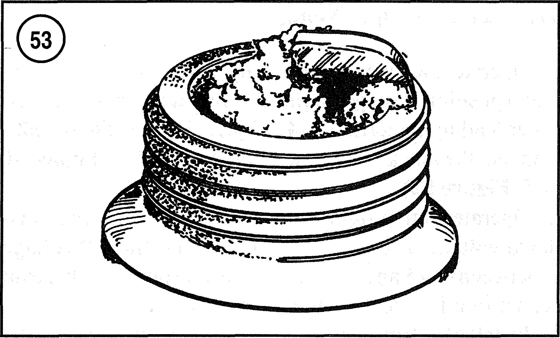
Detonation damage is the result of the heat and pressure in the combustion chamber becoming to great for the fuel being used. Fuel normally bums at a controlled rate that causes the expanding gasses to drive the piston down. If heat and pressure get too high, the fuel may explode vio- lently. These violent explosions in the combustion cham- ber cause serious damage to internal engine components. Carbon deposits, overheating, lean fuel mixture, over-ad- vanced timing and lugging are some of the conditions that may lead to detonation. Never use a fuel with a lower-than-recommended octane rating. Its use may cause detonation under normal operating conditions. The piston suffers most of the adverse effects of detonation. If detonation occurs, the engine has a pinging noise not un- like the pinging sometimes heard in automobiles. Out- boards in general are considerably noisier than automobiles, so the pinging noise is seldom detected. The engine likely has a rough idle and may seize. A compres- sion test will probably reveal one or more cylinders low on compression. Inspect the spark plug. The presence of aluminum deposits or melted electrodes (Figure 53) indi- cates probable detonation damage. To avoid repeat fail- ures, address the listed causes for detonation prior to returning the engine to service.
Preignition
Preignition is the result of a glowing object in the com- bustion chamber that causes early ignition. The wrong heat range spark plugs, carbon deposits and inadequate cooling are some of the causes of preignition. Preignition can lead to severe damage to the internal engine compo- nents. The primary component that is damaged is the pis- ton. The damage is very similar to detonation, as the early ignition causes the heat and pressure to become too great for the fuel being used. It explodes violently, causing a melted effect on the piston dome. It is not uncommon to have a hole form in the dome of the piston where preignition has occurred. As with detonation damage, the engine runs poorly, particularly at idle. When the com- pression test is performed, one or more cylinders may have low compression. Inspecting the spark plugs likely CHAPTER THREE
reveals aluminum deposits (Figure 53) consistent with detonation failures. Power head repair procedures are in Chapter Eight. To avoid repeat failures, address and cor- rect the causes of preignition before returning the engine to service.
Engine Seizure
The power head can seize at any speed. Normally the engine does not seize up at high speed as the engine typi- cally loses power gradually. Always inspect the gearcase before removing the power head. Gearcase failures can prevent the power head from rotating. Refer to Gearcase in this chapter to inspect the gearcase for metal contami- nation. The gearcase can also be removed to check for gearcase seizure as instructed in Chapter Nine. Repair the gearcase if the power head turns freely with the gearcase removed. Refer to Chapter Eight for power head removal, repair and installation procedures.
Water Entering the Cylinder
Water can enter the cylinder from a number of areas. Water in the fuel, water entering the front of the carbure- tor, leaking exhaust coverlgaskets, leaking cylinder head and/or gaskets and cylinder block internal leak can allow water to contaminate the engine. The typical symptom of water intrusion, is rough running, particularly at idle. The engine may run correctly at higher speeds. Verify water intrusion when the spark plugs are removed. Water is likely present on the spark plugs, and a white deposit may be present. Remove the cylinder head following the in- structions in Chapter Eight. Compare the wet cylinder(s) with the dry cylinder(s). A cylinder with water intrusion usually has significantly less carbon deposits on the pis- ton, cylinder walls and cylinder dome. Rust or corrosion may be present on the reed valves and lor other compo- nents. Leakage in the cylinder block can be difficult to
TROUBLESHOOTING AND TESTING
Compression gauge -
find. Casting flaws, pinholes and cracks may or may not be visible. Replacement of the cylinder block and/or cyl- inder head is required if water is entering the cylinder and no visible gasket leakage can be found. Continued opera- tion with water intrusion will result in engine failure.
Blown Cylinder Head Gasket
A blown cylinder head gasket results from a failure of the gasket that seals the cylinder head to the cylinder block. Symptoms of a blown head gasket include water entering the cylinder(s), overheating (particularly at lower engine speeds), rough running (particularly at lower en- gine speeds) and noises coming from the cylinder head to cylinder block mating surface. Refer to Compression Test in this chapter and perfom a compression test if a blown head gasket is suspected. Low or uneven compression may or may not indicate a blown head gasket. A slight leakage can cause the listed symptoms, yet it may not be detected by a compression test. Only removal and inspec- tion of the gasket and mating surfaces will identify a fail- ure. Refer to Chapter Eight for the cylinder head removal procedure. Compression Test
A compression gauge (Figure 54) and adapter are re- quired to perform a compression test. 1. Remove the spark plugs and connect the spark plug leads to an engine ground. 2. Install the adapter and compression gauge (Figure 54) into the No. 1 spark plug hole. Position the throttle in the wide-open position during testing. 3. Stand clear of the remaining spark plug openings dur- ing testing. Observe the compression gauge and operate the manual or electric starter. Ensure that the engine has made a minimum of 10 revolutions and the cranking speed is at or above 350 rpm. Record the compression reading. 4. Repeat Steps 2 and 3 for the remaining cylinders. Re- cord all cylinder compression readings. 5. Compare the readings with the specification listed in Chapter Eight. 6. Position the throttle in the closed position. Remove the compression gauge and adapter. Install the spark plugs and leads.
COOLING SYSTEM
WARVING Stay cleaF- of the pr*opeller shaft while run- ning an engine on a Jlzalz/test device. For safe@ rpenzove the propeller befo~*e .erunning tlze engine or ~jlzileperfor~ning test. Disco~z- nect all spark plug leads and batteiy con- nections before r-ernovirzg or installing the pr*opeller
CA UTION Never run an outboard without providing cooling water Use either a test tank or jlush/test device. Remove the propeller be- fore running the engine on a Jlush/test de- vice. Use a suitable testpl*opeller to run the engine in a test tank.
Cooling System Description
The drive shaft in the gearcase drives the water pump, which is mounted on the drive shaft (Figure 55). The wa- ter is pumped to the exhaust area of the power head, then to the cylinder block and heads. The water exits the power head near the power head mounting surface and travels out through the drive shaft housing. As the water travels through the power head, it absorbs heat and can-ies it away. If the engine is overheating, the problem is that wa- ter is not flowing through the power head with sufficient
70 CHAPTER THREE
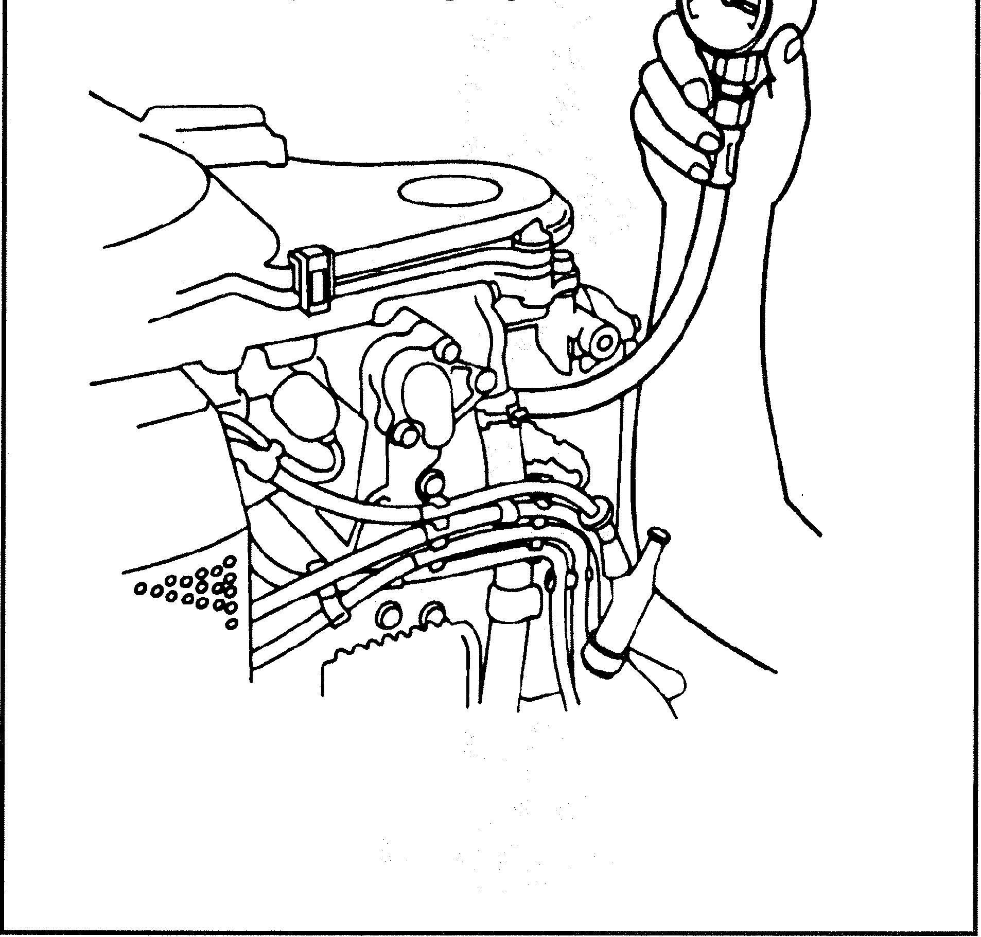
volume or is not absorbing the heat. All models are equipped with a thermostat (Figure 56) to help maintain a minimum power head temperature and improve low speed running conditions. They work by restricting the exiting water until a minimum water temperature is at- tained.
A stream of water is visible at the rear of the lower mo- tor cover when water exits the power head. The fitting may become blocked with debris and stop the flow of wa- ter. Clean the passage with a small, stiff wire brush. In- spect the cooling system if the water stream is still not present. As with all models, never run the engine without supplying it with cooling water.
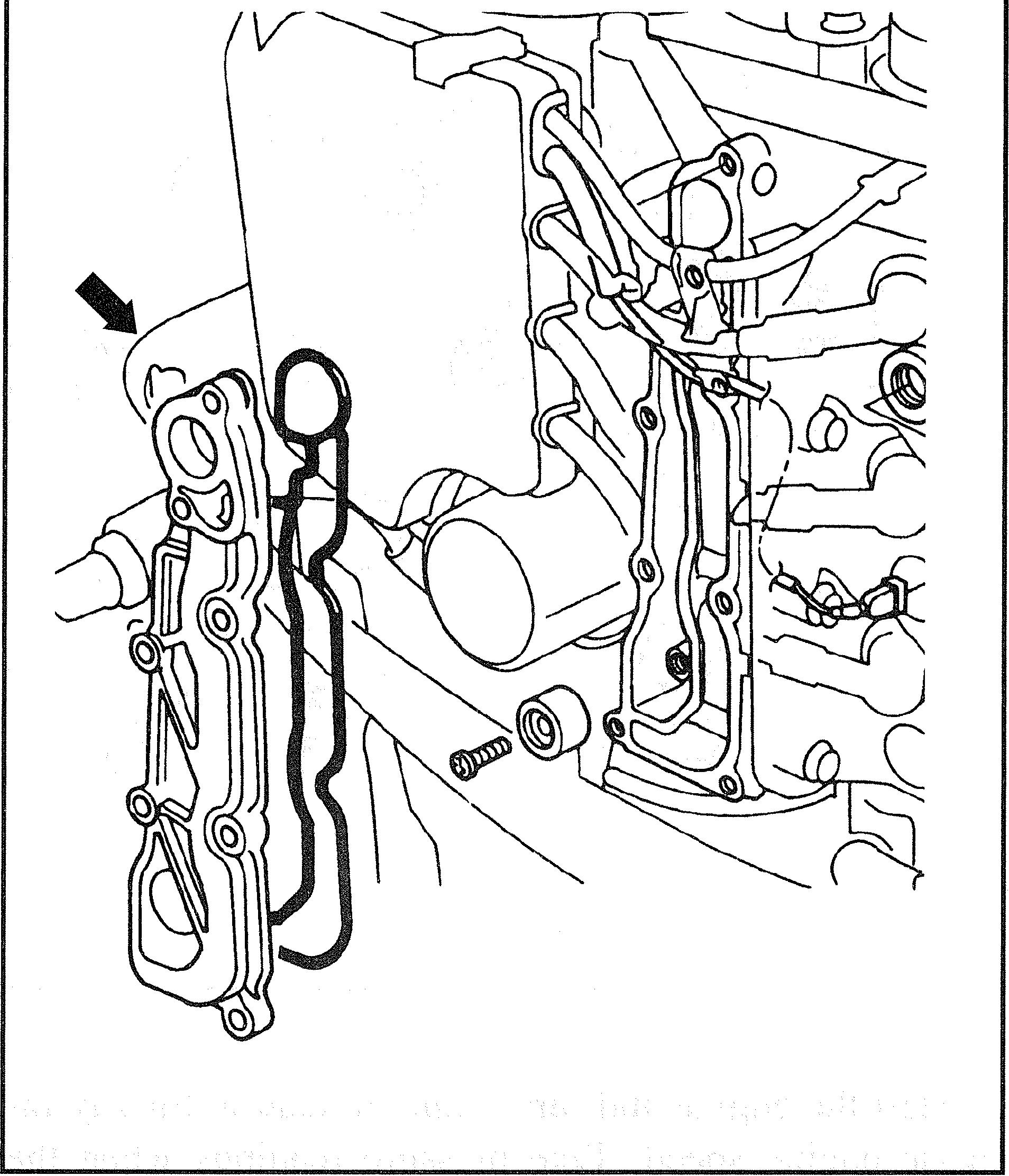
Cooling System Inspection
If the overheat warning horn sounds or the water stream is not present at the rear of the engine, perform the follow- ing: 1. Inspect and repair the water pump in the gearcase. Re- fer to Chapter Nine. 2. Inspect and test the thermostat if overheating occurs and the water pump is in good condition. Refer to Ther- mostat Testirzg in this chapter. 3. If no faults can be found with the water pump, thermo- stat or water pressure relief valve (if so equipped), inspect the exhaust water jacket (Figure 57, typical) for debris and deposit buildup. Rocks, pieces of the water pump, sand, shells, or other debris, may restrict water flow. Salt, calcium or other deposits can form in the cooling passages and restrict water flow. 4. Excessive deposit buildup acts as an insulator and pre- vents the water from absorbing the heat from the power head. Use a cleaner specifically designed to dissolve this type of deposit. Make sure the cleaner used is suitable for use on aluminum material. Always follow the manufac- turer's instructions when using these products. These cleaners are usually available at marine specialty stores. 5. It is necessary to remove the water jackets when in- specting cooling passages. Refer to Chapter Eight for wa- ter jacket removal and installation.
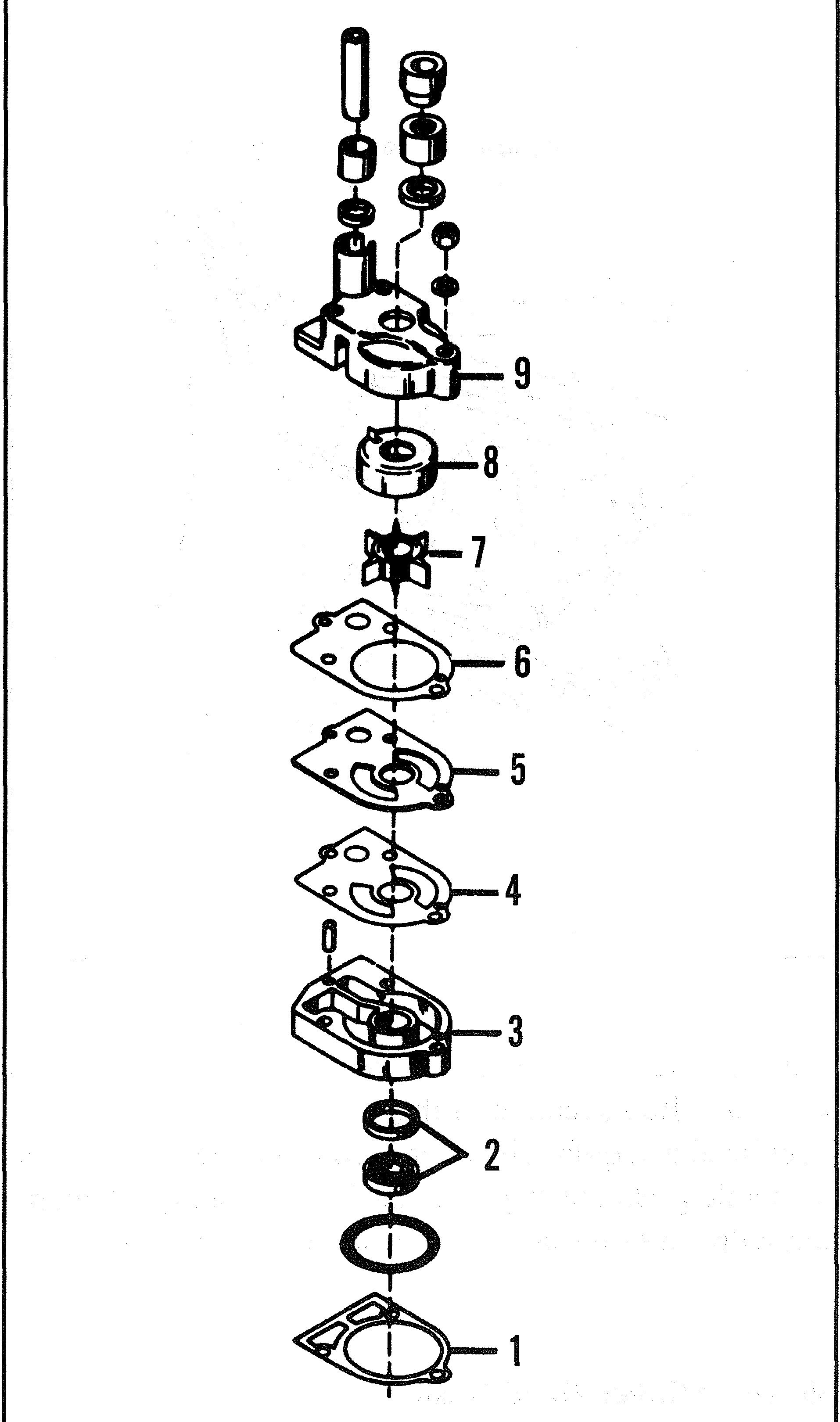
Engine Temperature Verification PRESSURE TYPE WNER PUMP
1. Gasket 2. Oil seal 3. Water pump base 4. Gasket 5. Water plate 6. Gasket

If the engine may be overheating, always verifL the actual temperature of the engine using Thermomelt sticks (Figure 58). Thermomelt sticks resemble crayons and are designed to ture immediately after or during the suspected overheat condi- melt at a specific temperature. Hold the sticks against the cyl- tion. Hold different temperature sticks to the power head to inder head near the temperature sender or switch. On smaller determine the temperature range the engine is reaching. Stop engines that are not equipped with an overheat alarm, hold the the engme if the temperature exceeds 90" C (1 94" F) to avoid stick near the spark plug mounting area. Check the tempera- power head damage. Perform a complete cooling system in-
TROUBLESMQOTING AND TESTING

7 1

spection if overheating occurs. Test the overheat sensor or wa- ter pressure sensor if an alarm or gauge indicates overheating and the Thermomelt sticks indicate normal temperature. Troubleshooting an overheating problem with a flushhest at- tachment is difficult, as the water supplied through the hose masks cooling system problems. Perfonn this test with the en- gine in the water or use a test tank.
Thermostat Testing
Test the thermostat(s) if the engine is overheating or running too cool. Thermostat testing requires a thermom- eter, piece of string and container of water that can be heated. Refer to Chapter Eight to locate the thermostat cover and related components. Refer to Table 8 at the end of this chapter for thermostat opening temperatures. 1. Remove the thennostat(s) as described in Chapter Eight. Discard the thermostat cover gasket. With a string tied to the thermostat, suspend the thermostat (Figure 56) in a container of water. 2. Begin heating the water. Continue to heat the container while observing the temperature and thennostat. 3. The thermostat should begin to open at approximately 52" C (125" F) on 8-40 hp models and 60" C (140" F) on 40- 140 hp models. 4. Replace the thermostat if it opens below or above the specified temperature. 5. Install the thennostat with a new gasket following the instruction in Chapter Eight.
Overheat Sensor Test
The overheat sensor (Figure 59) is a heat-sensitive switch installed in the cylinder head to monitor engine temperature. The warning horn is connected in series with the overheat sensor. If the sensor detects a temperature greater than a predetermined limit, the sensor contacts close and cause the warning horn to sound a continuous tone when the key switch is on and the remote control le-