4 minute read
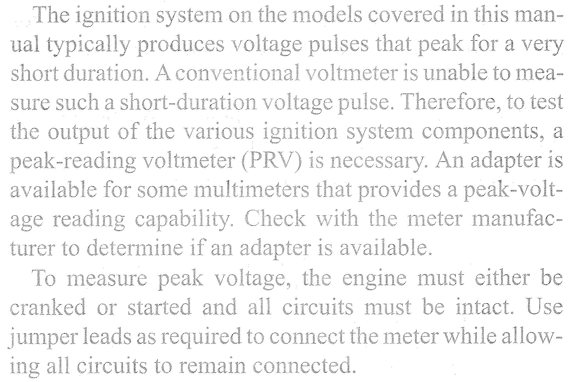
Test equipment


Chapter Three
Troubleshooting and Testing
There are three basic requirements for all internal com- bustion engines to run: proper ignition, unrestricted fuel supply, and adequate compression. When troubleshooting a problem, keep it simple. Define the symptom as closely as possible to one of the three functions, and then isolate the problem.
Expensive equipment or complicated test gear is not necessary to detennine whether repairs can be attempted at home. A few simple tests could prevent a large repair bill and lost time while the vehicle sits in a service depart- ment. However, do not attempt repairs beyond your abili- ties. Service departments tend to charge heavily for putting together a disassembled engine that may have been abused.
This chapter covers test equipment, troubleshooting preparation and systems or component testing.
Tables 1-8 are located at the end of this chapter.
NOTE This manztalprovidespr-ocedures and spec- ifications for standard products. Infornza- tion ?nay not apply if the product has been modzj?edJi.om its original factory condition or has afteirnzarket equipment installed. The use of aftermarket equipment or modzfication of the engine can affect erz- gine performatzce and tuning require- ments. For information on aftermarket equipment, consult a dealerslzip ilzat han- dles such eqztipment or is fat7ziliar with en- gine modification. Ifnecessa~y, contact the nza7zujactur"er of tlze aj?ernzarket eqtlipmerzt for informatioiz.
Multimeter TEST EQUIPMENT
Modern outboards use advanced electronic engine con- trol systems that help optimize the performance, reliabil- ity, and fuel economy. A multimeter is necessary to accurately test these control systems. A multimeter com- bines the functions of a voltmeter, ohmmeter, and amme- ter into one unit. Perform all tests using either an analog or digital multimeter. Refer to this section any time a ques- tion arises on using a multimeter.
A digital multimeter displays the readings on an LCD screen on the front of the meter. An analog multimeter


-7 Voltage Drop
Since resistance causes voltage to drop, resistance can be l~reas~~rec? on an active circuit using a voltmeter. This is a voltage drop test. Basicallj~, a voltage drop test measures the difference in voltage at the begini~ing of a circuit and ihe end of a oircuir xhile the circuit is being operated. If rhe circuit has 110 resisttince, there will be iio voltage drop (the meter wiii read zero). The more resistance in the cir- cnit, the higher the ~loltmeier reading will be. Generally, voltage drop readings of one or more volts are considered unsatisfactory. The advantage to tile ~oltage drop test compared to a resisrance test is hat the circuit is tested during operalion. It is i~npox-tant to remember that a zero reading duri~~g a voitage drop test is good, while a battery voltage reading :.could indicate ;m open circuit.
A voltage d.rop test is an excellent way to test solenoids, relays, battery cables and high-current electrical leads. To perfonn a voltage drop test, connect the positive meter lead to the voltage source (where electricity is coming from) and the negative meter lead to the load (where elec- tricity is going).
Resistance
Resistance is the oppesition to the flow of current ahroi.igh a circuit. Ohms are the unit ofmeasure for resis- . . tance. Use a.n ohr~li~~erer on?y on a c~ralit DP. component Illat is isolated (disconi3ected). The ahmmeter will be damaged if connticted to a circuitwith voltage present.
To measure resistaxce; tile olimmeter is typically con- nected in a series conizer:rior? (Figure 2). Because an ohm- Inerer is self-powered. it is of en used as a csntinuity tester in addition to measuring tester to cl~ecl: the integrity resistance. Use a continuity . . of a c~rcv.i,ri: or component and to check diodes. An 7;ni;ilty reading clpen circuit) indi- cates no co~~tir~uity scBik any other reading indicates con- . . tlnrrlty.
An ohmmeter, although usefi~iii: is uot aiways a good in- dicator of ignition system conditiol~. Phis is primarily be- cause resistance tests do not siinulate actual operating conditions. For example, he porn-er soarce in most ohm- nlciers is only 6-9 volts. A CDI charge cojl, how-ever, con~rnonly -produces 100-300 voks dming normal opera- tion. Such high voltage can cause coil insulation leakage t~ ikai ,~ + camlot bc detected with an ohmmeter.
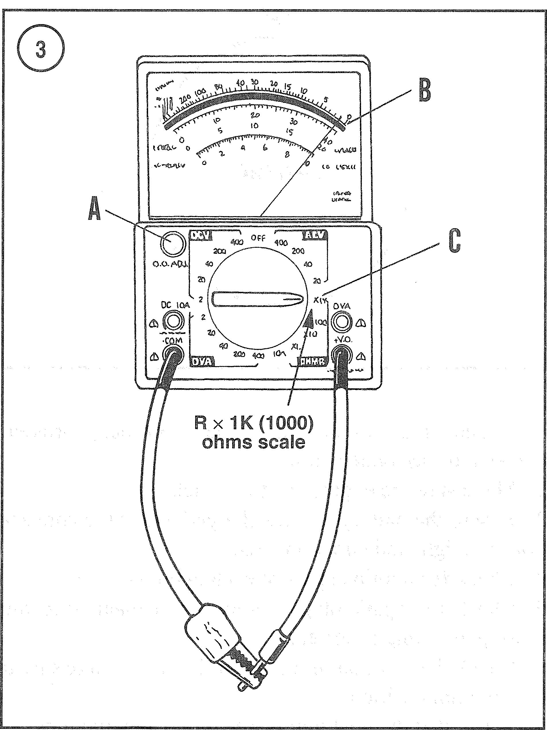
An analog ohlmeter mist be calibrated before each use and each time the scale is changed. Digital ohmmeters? hovjever, are usually a to-ranging and auto-scaling and do notrequire cziibratjon. To calibrate an analog meter, totioh the test leads together and kiru the adjust laob until rhc ncedle points exact:y at zero. See Figure 3.