Architecture Portfolio
Hamadi Braimah
1 1: Sequential Experiences 2: [Mis]fit / [Mal]function 3: Syracuse Youth Hostel 3 - 6 7 - 14 15 - 21
2 4: Redesigning
5: Tradition and Innovation 22 - 29 30 - 32 6: Representation 33 - 37
Spaces
1: Sequential Experiences
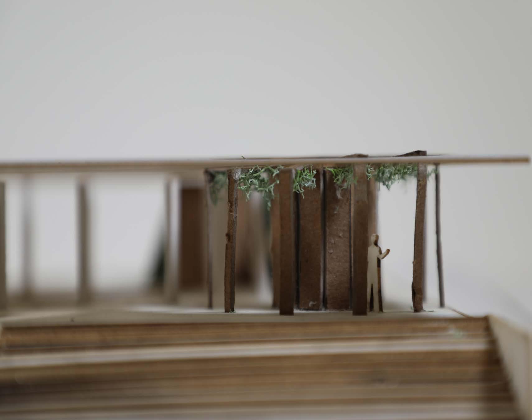
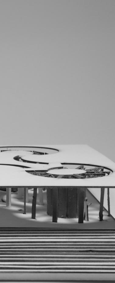
The aim of this project was to design an exhibition pavilion for a number of objects based on a theme. The theme for my section was mushrooms, and I decided to exhibit 3 species of Reindeer Lichen (C Rangiferina Lichen, C. Mtis Lichen and C Arbuscula Lichen) with a focus on the arctic region. Based on my research on reindeer lichen I had 3 main goals for the pavilion. First, I hoped my pavilion would highlight the effect of human activity on the arctic ecosystem and reindeer lichen through spatial juxtapositions. Secondly, I wanted my pavilion to provide a conducive environment for the different lichen species to grow based on their individual environmental needs. Lastly, I aimed for my pavilion to feature dynamic spaces that create an immersive and symbolic experience for visitors.

3


4
Shadows & Lighting Roof plan (voids)
Circulation & Movement
Pavilion Section
Axon of pavilion


5 1/8”=1’-0” 1FT 2FT 3FT 6FT 12FT SITE PLAN 1/4”=1’-0” 1FT 3FT BUILDING PLAN A C B


6
Model of Pavilion (1”:32’)
[Mis]fit / [Mal]function
This 2-part project looks at the movement of different bodies in space and the ethical implications of design decisions on accessibility for different groups of people. This made me realize the effect policy, society and the environment has on how designers create, define and manipulate space, which in turn affects the way different people occupy these spaces. I began questioning the way we define the ‘function’ or ‘malfunction’ of space and how interactions with said space makes people ‘fit in’ or become ‘misfits’. This project also developed my skills in digital fabrication , structural and spatial analysis, and methods of documentation and representation.

7
2:
For part 1, we were tasked with physically interacting with any object in 2 different ways (a conventional interaction and an uncoventional interaction), documenting and analyzing each interaction and using the analysis and a case-study building as a basis for a conceptual physical model. Diagrammatic documentation at each stage of the process was a fundamental aspect of Part 1.
LessUniformUpperBodyFrameIntervals(LargerForceofGravity=MoreExertion)

MoreUniformUpperBodyFrameIntervals(LowerForceofG
The object I chose was a bed. My first interaction on the top left was sitting up and then lying down on the bed (fit), while the second one on the top right was lying down and then sitting up on the bed (misfit). The reason I chose that to be my second interaction (misfit) rather than a more ‘unconventional movement’ was that the subtle differences between starting off with sitting up or lying down, was an aspect I wanted to explore as a result of the effect of gravity on someone with my height (tall) and stature (slim).
The diagram on the left, calls out the differences and similarities between the interactions frame by frame. It points out the interesting differences between the way my upper body and lower body move due to gravity, depending on whether I start off sitting up or lying down. This made me wonder if these differences will be just as apparent had the same interaction been conducted by someone that wasn’t as tall or slim as myself. Additionally, the diagram also emphasizes the rotational and orbitual movement of my body, centered around my hips which I identified as a pivot in both interactions.

8 PART 1 M o r e Unif orm LowerBodyFrameIntervals(LowerForceofGravity=LessExertion)
ravity=LessExertion) Less Uniform LowerBodyFrameIntervals(LargerForceofGravity=MoreExertion)
UPPER BODY LOWER BODY PIVOT LINE PIVOT LINE pivot Knees & Elbows Shoulders and Shins Necks and Ankles Faces and Feet
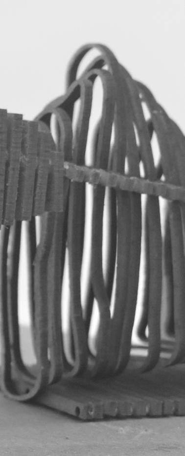
For this stage, I used my analysis of both interactions and the Koyasan Guest House (case-study building) in Japan, as a basis for a conceptual physical model. The model is made up of 3 sections which were based on the 3 parts of my body that were essential to the interactions (upper body, lower body and hips (pivot)). Each section was created by merging 2 abstract forms of the corresponding body parts from each interaction. These 3 sections were then pieced together to create an overall form that reflects the rotational quality of both interactions in elevation and the linear sequence of the Koyasan Guest House in plan. The Koyasan Guest House also has a continous repitition of structural frames throughout the building which served as an inspiration for the contoured aspect of the model I made. The contouring was also a design decision I made to allow for the model to be fabricated easily using a laser cutter, without foregoing the qualities I wanted the model to have. The diagram on the right shows all the pieces used in the laser cutting fabrication process.


9 1
12345678910111213141516171819202122232425262728293031323334353637383940414243 44 45464748495051525354555657585960616263646566
Model Scale - 1”:8’
10 Module Module 2 Module Linear stacking based on Koyasan Guest House Opening in center to resemble hallway form of Koyasan Guest House Sweep used to create rear side 3D form based on 2D abstraction Contouring utilized to replicate framing of Koyasan Guest House Sweep used to create front side 3D form based on 2D abstraction Linearized points of 3D forms to create unified module based on Koyasan Guest House, with overall form illustrating 2D movement Extracting of area from primary 2D movement abstraction Extracting of area from ‘misfit’ 2D movement abstraction Unified abstraction of misfit and primary movement Upper Body Lower Body Knees and pivot
This diagram is a cumulative representation of all the stages of part 1: from the interactions to the analytical diagrams to the final model.
PART 2
This part focuses on analyzing the case study building from Part 1 (Koyasan Guest House). These analysis include diagrams showcasing circulation, structure, tectonics, and more. These analysis then carry over into 2 models: a digital model that is a hybrid of the case study and the interaction from part 1, and a collaborative physical model using the same digital fabrication process from part 1.
The exploded axon on the left illustrates the different aggregation systems of the building which narrow down to a unit at the top. This unit is further analyzed in the second exploded axon above, with an emphasis on tectonic and structural systems. In this second axon, I used lineweights and hatches to communicate the analytical observations I made.
11 Glass
Wood 2
23'-8 23'-0" 5'-7 8'-8 53'-1 8'-8 10'-2
Wood
Concrete Metal Frish Galvanized Steel Corrugated Sheet
The plans and sections analyze the tectonics, structure and accessibility of a chunk of the building as well as the entire building. The Koyasan Guest House has some cubicles that can only be accessed using ladders, meaning these are inaccessible to people that may be unable to climb one. There are also some spaces that are too narrow for wheelchair users. These inaccessible spaces are shown in red, while the more accessible spaces are shown in purple.


12 1'-5 1'-4 1'-5 1'-5 15'-7 1'-8 7'-10 8'-5 4 23'-0" 7'-10 5 8'-5 7'-10 19'-8 4'-7" 2'-1" 1'-4 1FT 2FT 4FT 1/2”=1’-0” 1FT 2FT 4FT 1/2”=1’-0” 1/4”=1’-0” 1FT 2FT 3FT 4FT 8FT WHOLE PLAN & SECTION PART PLAN & SECTION Galvanized steel corrugated roofing sheet Ladder and support Mattress Bed Support Windows Spaces accessible to anyone living in guesthouse Spaces inaccesible to wheel chair users and individuals that can not utilize ladder Mattress foam Galvanized steel corrugated sheet Wood
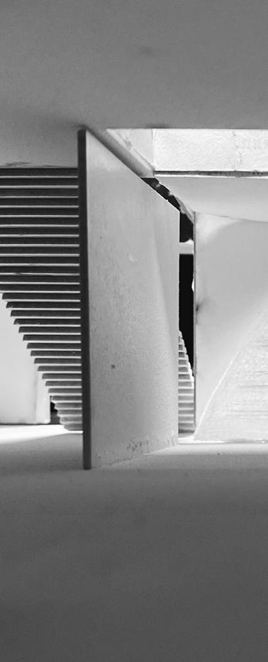
Model of a Chunk of Koyasan Guest House (1”:4’) - photos above and below
Study Model of Koyasan Guest House (Not to scale) - bottom photo
To create the hybrid model, I took sections of my interactions in part 1 and interpreted them as occupiable units in the Koyasan Guest House. The linear organization of the Koyasan Guest House served as a blueprint for the arrangement of these units which can be seen in the exploded axon above. The units themselves and the way they were organized, created a new system that deviated from the rectangular form of the guest house to one that features more curvilinear forms.
The deviation away from rectangular forms in the hybrid is seen best in the plan and section above that features a rotational and spiral form reflective of my interactions in part 1. Additionally, I used the units and their organization to solve the issue of accessibility. I utilized the organization of the units to eliminate the narrow spaces as well as the unit’s curvilinear form to create a ramp typology, creating more wheelchair access and overall accessibility for all bodies as shown in the section above.
13 65'-9 7'-11 5'-9" 8'-0" 8'-10 48'-9 17'-5 5'-2 16'-6 8'-0 8'-0 6'-4 8'-8" 7'-5" 31'-3" 4'-11 8'-11 16'-7 7'-1 48'-11 6'-1" 7'-5 Plan Section 1/4”=1’-0” 1FT 2FT 3FT 4FT 8FT 1/4”=1’-0” 2FT 4FT 8FT 2 3 Moduled based on movement of body, replacing room capsules in Koyasan guest house 2 Hallway spine based on rotational movement of body, replacing tectonic hallway frames of Koyasan guest house 3 Roof form based on hybrid of Koyasan guest house triangular roof and curving movement of body to unite room modules (capsules) and continue hallway spine logic Tectonic system embedded in roof
This final physical model for Part 2 was a collaborative task which was a hybrid of my partner (Miranda Anastasakis) and I’s interactions in Part 1 and our case study (Koyasan Guest House). Miranda’s abstract version of her interaction morphs out of the left side of the Koyasan Guest house pitched roof, while the abstract version of my interaction (similar to the physical model in part 1) completely envelopes the right side of the building. The contouring is kept once again to reflect the repeated structural frames the guest house has.


14
Built alongside Miranda Anastasakis (Model Scale - 1”:16’)
3: Syracuse Youth Hostel
In this project, the task was to design a youth hostel on an existing site. The design of the hostel had to be made using unit aggregations. There were 3 units we had to create which were small (reception, bathrooms and bedrooms) , medium (library, kitchen and lounges) and large units (dining area, large communal space). The existence of a site also meant consideration for the wider context such as existing infrastructure, circulation, neighborhood culture, frontages etc had to be made.

15
I started off with units that were based on my interactions in project 2. In Study Model 1, I explored the way the units fit together on a planar level and the opportunities that arise from scaling up and rotating the units. This gave me a number of ideas, regarding the programmatic logic I could arrive at based on these unit arrangements. In Study Model 2, I began looking at how to arrange the units based on the conditions of the site and how I could stack the units to create more sectional variation.
In Study Model 3, I began considering the facde of the hostel, and merging the ideas and conclusions I drew from study Model 1 and 2. I settled on having the private spaces (small units) on the exterior of the hostel, while using the medium and large units to create more public spaces and atriums in the middle of the hostel.


16
Study Model 1 (Model Scale - 1”:8’)
Study Model 2 (Model Scale - 1”:16’)
Study Model 3 (Model Scale - 1”:8’)
These axons on the left show my final design. The diagrams showcase the distinction between public and private spaces (public in the center, private on the outskirts), circulation around the hostel (elevators and stairs to all levels) and the organization of the units in the hostel (atriums and rooms)

The axon on the left shows the hostel on the site. The design takes the site into consideration by preserving the community garden which is the part of the site in the diagram with the rows of trees. The houses around the site meant there was a need to preserve privacy as well, which meant the height of the hostel was kept at a reasonable length. Lastly exits are placed conveniently to allow for access to the neighborhood’s commercial strip on the north end of the hostel.

17
The plans on the left reiterate the programmatic logic, whereby the bedrooms and bathrooms lie on the outskirts of the hostel, while the more public spaces like eating areas, kitchen, lounges, and atriums are found in the middle. Having such a centralized plan, encourages interaction between the residents which is an essential quality of a youth hostel.
The sections at the bottom recaptulate the sectional variation explored in Study Model 2. They also show how the circulation around the hostel enunciates the sequential experience the hostel design provides.


18 Scale: 1’=1/8” Scale: 1’=1/16” Scale: 1’=1/16” Atrium Private Main Lounge Mini Atrium Private Room Lounge/Library Mini Room Main Lounge Private Bathroom Private Elevator Private Room Private Private Ground Floor Atrium Above Central Circulation Space SECTION Reception Kitchen and Dining Area Private Bedroom Private Bedroom Balcony Balcony Mini Atrium 18'-3 10'-3 5'-11 5'-8 2'-4 17'-3 6'-10 31'-0" 15'-0" SECTION 1 Scale: 1’=1/8” Scale: 1’=1/8” Bathroom Sauna Bedroom Bedroom Bedroom Bedroom Main Lounge Communal Area Bedroom Bedroom SECTION 2 Scale: 1’=1/8”


19
Model of Hostel (1”:8’)


20
East-side perspective view of the interior. Digital model (left), Physical model (right)
North-side perspective view of the interior. The digital model on the left features a mural in the back, reflecting the neighborhood’s thriving arts scene.
North-side perspective view of the exterior. Digital model (left), Physical model (right)
Sturctural and climatic analysis spread of Hostel for ‘Introduction to Buildings and Structures’ (ARC 121)


21
June 21 December 21 W S E N NNE NE ENE ESE SE SSW SW WSW WNW NW NNW SSE m/s 0.00 1.00 2.00 3.00 4.00 5.00 6.00 7.00 8.00 9.00 10.00 W S E N NNE NE ENE ESE SE SSW SW WSW WNW NW NNW SSE Floor & Rood Lateral Support Beams Vertical Support Beams Private Unit Aggregation Structure Public Unit Aggregatiion Structure Roof 2nd Floor 1st Floor Structure of A Public Unit Structure of A Private Unit Vertical Load Curvilinear Load Lateral Loads Atrium allowing for light during darker winter months, with overhang to provide shading during winter Bedroom windows facing East to receive some sunlight during later hours of the day without receiving maximum intensity SECTION 1 Balcony Balcony Mini Atrium SECTION 1 Scale: 1’=1/8” Natural Light Coming Through atrium, illuminating public space in both winter and summer Natural Light Into Reception Area Sunroof Creating Moments of Illumination on Lower Public Levels Light into Rooftop Terrace Natural Light Into Kitchen and Dining Area Wall Condition to Curb Excessive Summer Light and Heat Roof Condition to Curb Excessive Summer Light and Heat December 21st a.m (Winter Solstice) June 21st a.m (Summer Solstice) Scale: 1’=1/8” W E 13'-0" 8'-0" 48'-0" 36'-0" 16'-6" 16'-0" 8'-0" Hot air leaving through atriums, creating stack ect (useful during summer months) Cross Ventilation through central public space Cross Ventilation through various bedrooms, allowing for passive cooling SECTION Scale: 1’=1/8”
4: Redesigning Spaces
This section looks at 4 projects I’ve worked on whereby I have redesigned spaces using a variety of media. They each involve a number of stakeholders and constraints presenting unique challenges. Additionally, the sequence of projects in this section, become increasingly more hands-on, starting with concepts and ideas and ending with physically built spaces, symbolizing the nature of design.

22
PROJECT 4.1
Redesigned one of my school’s IT labs (IT lab 1) as part of my IB MYP Personal Project. I identified the aesthetic and functional issues in the lab based on feedback from stakeholders and designed a well-recieved remodel.
The sketch above is a floorplan sketch of my one of my initial designs. The advantage of this design was that it used the space better by allowing for collaborative desks, reducing congestion and providing a better viewing angle of the board (for students) and the back (for teachers).

The digital floorplan on the left has accurate dimensions of the space and was made using Homestyler.

23
Digital render of design made using SketchUp and Vray, exhibiting improved layout, aesthetics, lighting, and others. I also made a detailed video showing all stakeholders how the design resolves all the problems they highlighted, with eventually 95% of stakeholders approving of the design


24
Picture of IT lab 1, showing aesthetic issues, congestion, lack of natural lighting, collaborative desks and ventilation which stakeholders identified in surveys I sent out
PROJECT 4.2
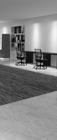
I was selected by the CAS (Creativity, Activity, Service) Department at my high school to redesign their office. My design aimed to address issues regarding aesthetics, space, storage and cooling.


25
Using Homestyler, I designed this interior space, addressing the issues raised by the department as well as the ones I observed.
PROJECT 4.3
I was selected by my high school’s IT Department to redesign one of its IT labs (IT lab 2) into a creative workroom. The department wanted a space that allows for both collaborative and individual work, provides storage for various materials and features a layout and design that is both functional and aesthetically pleasing.
Using Homestyler, I designed a space that featured a central collaborative space, work desks, storage space for electronic or artistic materials, as well as desk space for teachers that simultaneously provided privacy and a viewing angle that allowed them to monitor students.


26
PROJECT 4.4
I got first-hand experience teaming up with a local architect in Ghana to remodel a house in the capital city. I took up the role of budgeting, purchasing materials, interacting with clients and restructuring and improving the layout and aesthetics of both interior and exterior spaces.
This was the final floor plan rough sketch for the ground floor, achieved after sketching a number of possible redesigns and reaching a compromise with the architect’s own ideas
I made a rough pencil sketch of the old floor plan of the clients’ house and took notes of it’s issues. This floor needed more bathrooms, lighting in the hallway, better circulation between spaces and a pantry and office.


This was the final floor plan rough sketch for the first floor which was entirely my design. This floor needed an additional living room, bedroom, as well as a balcony, porch, and an atrium looking down at the living room downstairs.

27
With SketchUp, I created a rough digital model of the proposed design, which the architect used in creating a more sophisticated 3D render to present to the clients which they approved

Due to budgetary constraints, only part of the house had an additional level. This made it essential to maximize the space on the new level, while also making the layout conducive for further expansion in the future.

28
In 2 years, we converted the house from a one-storey bungallow to a two-storey modern Ghanaian house meeting the clients’ specified needs, improving lighting, layout, movement around the house, and ventilation.


Due to budgetary constraints during the 2 years spent on the project, some comprimises had to be made but the overall vision we had with our client was brought to fruition.

29
5: Tradition and Innovation
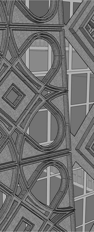
This project focuses on reconceptualizing the traditional architecture of the Hausa tribe in West Africa, by fusing modern urban elements. I combined traditional architectural elements from my tribe with that of modern mainstream architecture to reimagine traditional Hausa architecture and push the boundaries of tradition and innovation.

30
This is an elevation sketch of Side 2 which mostly features more ‘modern’ urban elements such as horizontal glass panels or windows, linear frames, and monolithic pillars reminiscient of Greko-Roman architecture, however with a more Hausa-esque form

This is an elevation sketch of Side 1 which mostly features Hausa-Fulani architectural characteristics which are the rufi (dome), zankwaye (pinnacles), and the northern knot which is a pattern and symbol of the tribe

31
I created a 3D model with SketchUp that combines Hausa-Fulani architecture with that of modern urban archtecture. Despite the 2 sided approach, features like the dome, pillars, pinnacles and glass are prominent on all sides, uniting the 2 sections

A closer look at the patterns on Side 1 show the intricacies of Hausa craftmanship which is one of the prime features of this design. I was inspired by the bronze corona on the surface of the Musuem of African American History and Culture designed by David Adjaye as well as the patterns on the walls of the Hausa Kings’ palaces in Northern Nigeria.

32
6: Representation
These are a few projects from my Representation class (ARC 182) showcasing my representational skills in Adobe Illustrator, Rhino and Photoshop.
33
Structural Matrices (Black and White)

34

35
Structural Matrices (Colored)

36
Topographic Fields Illustration

37
Final Entourage Illustration
