T E C H N I C A L PA P E R
Cure behavior of optical fiber coatings with UV-LED Hirofumi Uchida, Kumpei Kobayashi, Takumi Nakajima, Noriyasu Shinohara JSR Corporation, Tsukuba Laboratories Tsukuba, Ibaraki, Japan +81-29-856-1218 · hirofumi_uchida@jsr.co.jp
Abstract
Table 1. Components of the coatings
It was studied that the cure behavior of optical fiber coatings on films cured with a UV conveyor or mock fibers cured with the draw tower simulator using UV-LED. UV dose and intensity of the draw tower simulator were estimated with photo initiator consumption in a coating. Temperature of a coating or UV intensity affected their cure behaviors strongly on a primary coating, weakly on a secondary coating. Unique behaviors were appeared at low work speed in conveyor curing. They came probably from spatial distribution of intensity. In mock fiber experiment, monomer-11 contained in a primary coating showed reverse behavior. It came probably from photo initiator consumption in a coating at low line speed in high intensity curing.
Primary coating
Secondary coating
Components Oligomer-1 Monomer-11 Monomer-12 Photo initiator (PI) Oligomer-2 Monomer-21 Monomer-22 Photo initiator (PI)
Functionality 0 - 2, mixed 1 1 2 2 2 -
2.2 UV-LED
Keywords: optical fiber coating; cure behavior; UV-LED;
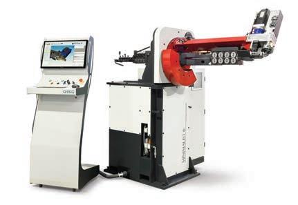
A high-power UV-LED was used to make cured films and mock fibers. It has 20 mm x 260 mm of emission window and no condenser lens. If it was used for making a mock fiber, the mirror designed for optical fiber manufacturing was mounted on it.
1. Introduction
2.3 Analysis on Thermal Properties
conveyor; draw tower simulator
UV-LED has been focused for the optical fiber manufacturing because it can decrease the manufacturing cost and the environmental load of mercury by using UV-LED instead of metal halide lamp. Furthermore, UV-LED is superior to metal halide lamp at the point of easy and accurate control of UV intensity without spectrum change. This is a good advantage for the evaluation of coating materials in laboratories. We have usually used a UV conveyor or the draw tower simulator which is a remodeled rewinder to apply coatings on a metallic wire as a substitute for a glass fiber. The films cured with a UV conveyor are relatively easy to measure various properties. However, they have slightly different properties from the coatings applied on glass fibers or mock fibers. It is important to confirm the difference of cure behaviors between the films and the mock fiber coatings in order to realize the reason of the difference in the properties. Some investigations were already studied to clarify the cure behavior of coating in films or mock fibers. [1], [2]. This study was focused to compare the cure behaviors of films and mock fibers cured with UV-LED at near conditions as possible.
2. Experiment 2.1 Materials
A primary coating and a secondary coating were prepared in our laboratories to have favorited young’s modulus and viscosity for optical fiber coatings. These formulations are described in table 1. The components are widely used for commercial optical fiber coatings.
1.3.1 Heat of Polymerization. Heat of polymerization of each coating was measured with photo-DSC at room temperature under light exposure of 33 mW/cm2 by a spot type UV-LED. 1.3.2 Specific Heat Capacity. Specific heat capacity of each coating film and metallic wire used for mock fiber was measured with DSC according to Japanese industrial standard K 7123. The films were cured at UV dose of 0.5 J/cm2 by a metal halide lamp under nitrogen.
2.4 Preparation of Films
Each coating was sandwiched between a glass plate of 3 mm thickness and a clear film with a spacer. It was cured with a UVconveyor mounted UV-LED described at 1.2 at right angle to the work moving direction. Curing was run at room temperature (25 °C) or 100 °C controlled with heating device. After cure, the film was removed from the film and the glass plate. Other conditions were shown below. Output of UV-LED; 25 %, 100 % Work distance; 20 mm Work speed; 4 - 120 m/min Film thickness; Around 0.23 mm
2.5 Preparation of Mock Fibers
Mock fibers, which had metallic wires in spite of glass fibers in optical fibers, were manufactured with the draw tower simulator (DTS), the remodeled rewinder. Manufacturing conditions were shown below. Coatings; Secondary single coat, Primary / secondary by wet-on-wet Temperature of coatings; 40 °C Number of UV-LED; 1 Line speed; 200 - 1200 m/min Diameter of Metric wire; 0.125 mm Diameter of primary layer; 0.19 mm
6 9 T H I W C S C O N F E R E N C E - O C T O B E R 2 0 2 1 W I R E J O U R N A L I N T E R N AT I O N A L
71