14 minute read
Noriyasu Shinohara


Hirofumi Uchida, Kumpei Kobayashi, Takumi Nakajima, Noriyasu Shinohara
JSR Corporation, Tsukuba Laboratories Tsukuba, Ibaraki, Japan +81-29-856-1218 · hirofumi_uchida@jsr.co.jp
Abstract
It was studied that the cure behavior of optical fiber coatings on films cured with a UV conveyor or mock fibers cured with the draw tower simulator using UV-LED. UV dose and intensity of the draw tower simulator were estimated with photo initiator consumption in a coating. Temperature of a coating or UV intensity affected their cure behaviors strongly on a primary coating, weakly on a secondary coating. Unique behaviors were appeared at low work speed in conveyor curing. They came probably from spatial distribution of intensity. In mock fiber experiment, monomer-11 contained in a primary coating showed reverse behavior. It came probably from photo initiator consumption in a coating at low line speed in high intensity curing.
Keywords: optical fiber coating; cure behavior; UV-LED; conveyor; draw tower simulator
1. Introduction
UV-LED has been focused for the optical fiber manufacturing because it can decrease the manufacturing cost and the environmental load of mercury by using UV-LED instead of metal halide lamp. Furthermore, UV-LED is superior to metal halide lamp at the point of easy and accurate control of UV intensity without spectrum change. This is a good advantage for the evaluation of coating materials in laboratories. We have usually used a UV conveyor or the draw tower simulator which is a remodeled rewinder to apply coatings on a metallic wire as a substitute for a glass fiber. The films cured with a UV conveyor are relatively easy to measure various properties. However, they have slightly different properties from the coatings applied on glass fibers or mock fibers. It is important to confirm the difference of cure behaviors between the films and the mock fiber coatings in order to realize the reason of the difference in the properties. Some investigations were already studied to clarify the cure behavior of coating in films or mock fibers. [1], [2]. This study was focused to compare the cure behaviors of films and mock fibers cured with UV-LED at near conditions as possible.
2. Experiment
2.1 Materials
A primary coating and a secondary coating were prepared in our laboratories to have favorited young’s modulus and viscosity for optical fiber coatings. These formulations are described in table 1. The components are widely used for commercial optical fiber coatings.
Table 1. Components of the coatings
Primary coating
Secondary coating Components Functionality Oligomer-1 0 - 2, mixed
Monomer-11 1
Monomer-12 Photo initiator (PI) Oligomer-2 Monomer-21 1
2 2
Monomer-22 Photo initiator (PI) 2
2.2 UV-LED
A high-power UV-LED was used to make cured films and mock fibers. It has 20 mm x 260 mm of emission window and no condenser lens. If it was used for making a mock fiber, the mirror designed for optical fiber manufacturing was mounted on it.
2.3 Analysis on Thermal Properties
1.3.1 Heat of Polymerization. Heat of polymerization of each coating was measured with photo-DSC at room temperature under light exposure of 33 mW/cm2 by a spot type UV-LED. 1.3.2 Specific Heat Capacity. Specific heat capacity of each coating film and metallic wire used for mock fiber was measured with DSC according to Japanese industrial standard K 7123. The films were cured at UV dose of 0.5 J/cm2 by a metal halide lamp under nitrogen.
2.4 Preparation of Films
Each coating was sandwiched between a glass plate of 3 mm thickness and a clear film with a spacer. It was cured with a UVconveyor mounted UV-LED described at 1.2 at right angle to the work moving direction. Curing was run at room temperature (25 °C) or 100 °C controlled with heating device. After cure, the film was removed from the film and the glass plate. Other conditions were shown below.
Output of UV-LED; 25 %, 100 %
Work distance; 20 mm
Work speed; 4 - 120 m/min
Film thickness; Around 0.23 mm
2.5 Preparation of Mock Fibers
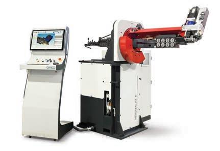
Mock fibers, which had metallic wires in spite of glass fibers in optical fibers, were manufactured with the draw tower simulator (DTS), the remodeled rewinder. Manufacturing conditions were shown below.
Coatings; Secondary single coat, Primary / secondary by wet-on-wet
Temperature of coatings; 40 °C
Number of UV-LED; 1
Line speed; 200 - 1200 m/min
Diameter of Metric wire; 0.125 mm
Diameter of primary layer; 0.19 mm
Diameter of secondary layer; 0.24 mm
2.6 Young’s Modulus
Young’s modulus was measured using tensile testing machine at 0.04 min-1 strain rate under 23 °C, 50 %RH. The modulus was defined as the secant modulus at 2.5% elongation.
2.7 Dynamic Mechanical Analysis (DMA)
DMA measurements were conducted at frequency of 1 Hz in tensile and temperature ramp mode. The equilibrium modulus was defined as the storage modulus (E’) at 140 °C.
2.8 Residual Percentage of Components
Each film or mock fiber was soaked in organic solvent to derive unreacted components. After deriving, the solvent was analyzed using GC and GPC to determine the residual percentage of the components.
3. Results and Discussion
3.1 Thermal Analysis
Thermal properties of the materials were summarized in Table 1. Specific heat capacity of glass was cited from technical data by a supplier. The secondary coating had almost twice larger heat of polymerization than the primary coating. It was due to the reactive functional group density. They had similar value on heat per mole of reactive functional group. The comparison of specific heat capacity and density leads that the metric wire used for mock fiber had twice lager heat capacity per volume than glass. Temperature rise by cure was estimated from their thermal properties under ideal condition, adiabatically and thermally equilibrated. The results were shown in Table 2. The temperature rise of the secondary coating was very high. So, the primary coating was cured with heating by the secondary coating in weton-wet process. Actual temperature of coatings during cure is determined the balance of heat generation and conduction. And, it has a distribution in a coating. There was no doing to estimate it in this study. One attention in conveyor curing was that lower work speed makes cure condition be lower intensity and actual temperature, because almost cure reaction was generated at the low intensity edge of irradiation. It would complexify cure behavior in UV conveyor curing.
Primary coating Secondary coating Metric wire
Glass
Table 2. Thermal Properties
Heat of polymerization (J/g)
Specific heat capacity (J/g.°C) 50 °C 100 °C 150 °C Density (g/cm3)
134 2.1 2.3 2.5 1.1
254 1.8 2.0 2.1 1.2
- 0.42 0.43 0.44 8.9
- 0.80 0.83 0.88 2.2
Table 2. Estimation of Temperature Rise by Cure under Ideal Condition
Primary coating Secondary coating
Mock fiber
Optical fiber Before cure
40 °C
40 °C
Wire; 25 °C Coatings; 40 °C Glass; 40 °C Coatings; 40 °C After cure
100 °C
170 °C
100 °C
120 °C
3.2 Consumption of PI and Estimation of UV Dose in Mock Fiber Manufacturing
Figure 1 shows residual percentage of photo initiator (PI) in films cured at 25 °C, 100 % output of UV-LED. PI was consumed along theoretical way.
The primary coating; [PI] / [PI]0 = e -2.7 Q (1)
The secondary coating; [PI] / [PI]0 = e -1.2 Q (2) [PI]; Concentration of PI [PI]0; Concentration of PI before irradiation Q; UV dose (J/cm2) PI in the primary coating was more quickly consumed than in the secondary coating. Used PI was an intramolecure photocleavage type photo initiator. So, low consumption rate in the secondary coating might be brought by energy transfer to the matrix or recoupling of generated radicals due to low diffusion rate in the highly crosslinked matrix [3]. Consumption of PI was not affected by intensity or temperature (Figure 2, 3). UV dose and intensity in mock fiber manufacturing were able to be estimated from PI concentration in secondary single coated mock fibers. The results are shown in Table 3.

Figure 1. Residual percentage of PI in films cured at 25 °C, 100 % output of UV-LED

Figure 2. Residual percentage of PI in secondary coating films cured at various conditions
Figure 3. Residual percentage of PI in secondary single coated mock fibers vs. line speed / output of UV-LED
Table 3. Comparison of intensity and UV dose at 100 % output of UV-LED

Intensity (W/cm2) UV dose (J/cm2) Conveyor 9 (peek value) 0.6 at 34 m/min Draw tower simulator (estimated) 30 0.6 at 800 m/min
3.3 Cure Behaver of Primary Coating Films
Young’s modulus of primary coating films vs. UV dose is shown in Figure 4. Young’s modulus was strongly affected by temperature and intensity. It is known that the modulus of a rubber state material such as cured primary coating is determined by crosslink density [4]. Higher temperature and intensity decreased reaction of the difunctional oligomer, because termination reaction, radical coupling or hydrogen abstraction, might be enhanced. Figure 5 shows Young’s modulus of primary coating films vs. work speed. Curiously Young’s modulus was similar value in each intensity condition at low work speed. More investigations are required to clarify the inevitability. Typical residual percentage of components are shown in figure 6. Oligmer-1 was not decreased under 8 %, because no-functional oligomer was contained in it. Monomer-11 and monomer-12 was similar behavior. Residual percentage of monomer-11 at each cure conditions vs. UV dose is shown in Figure 7. Reactivity of monomer-11 was reduced by high temperature or high intensity. The slopes of the residual percentage were similar value. It suggests that reactivity reducing was generated in the less UV dose range. If the residual percentage was compared at the same work speed (Figure 8), the residual percentage at high intensity was constantly lower than at low intensity in contrast to Young’s modulus. Figure 9 shows relationship between the residual percentage and Young’s modulus. The films cured in higher intensity or higher temperature condition had lower young’s modulus. One of hypotheses is decrease of crosslinking by polymerized chain length shortening due to rising of termination reaction. It is one of factors contributing to the tendency shown in Figure 5.

Figure 4. Young’s modulus of primary coating films vs. UV dose
Figure 5. Young’s modulus of primary coating films vs. work speed
Figure 6. Residual percentage of components in primary coating films cured at 25 °C, 100 % output of UV-LED


Figure 7. Residual percentage of monomer-11 in primary coating films vs. UV dose
Figure 8. Residual percentage of monomer-11 in primary coating films vs. work speed
Figure 9. Young’s modulus vs. residual percentage of monomer-11 in primary coating films


3.4 Cure Behaver of Secondary Coating Films
Young’s modulus of secondary coating films vs. UV dose is shown in Figure 10. It was less affected by temperature and intensity. Cure condition of 100 °C and 100 % output made Young’s modulus slightly lower. Residual percentage was too little to use for probe into cure behavior of secondary coating. Equilibrium modulus was measured instead. It is the modulus at rubber state as same as Young’s modulus of the primary coating. Figure 11 shows equilibrium modulus of secondary coating films vs. UV dose. Equilibrium modulus showed similar behavior as Young’s modulus expect dropping in high UV dose range at 25 °C curing. Figure 12 shows them vs. work speed. Figure 13 shows storage modulus (E’) cured by UV dose of 0.7 J/cm2 or 5 J/cm2 at 25 °C, 100 % output. The film cured by 5 J/cm2 had higher E’ at room temperature and lower equilibrium modulus. The slopes of E’ in middle temperature were different. Such phenomenon is ceased by the difference of degree of microphase separation [5]. Lower actual temperature of the coating in curing made degree of microphase separation lower, and equilibrium modulus lower.

Figure 10. Young’s modulus of secondary coating films
Figure 11. Equilibrium modulus of secondary coating films vs. UV dose
Figure 12. Equilibrium modulus of secondary coating films vs. work speed


Figure 13. Storage modulus (E’) of secondary coating films cured at 25 °C, 100 % output
3.5 Cure Behavior of Dual Coated Mock Fibers
Residual percentage of monomer-11 in mock fibers is shown in Figure 14. At low line speed, lower output made residual percentage lower. It caused by low content of PI in 100% output curing, as shown in Figure 15. The value in Figure 15 was average in primary and secondary layer. The value in primary layer was inferred lower than it from film experiment. The reverse tendency was not reproduced in film curing. The irradiation distribution in the conveyor curing might hide the reverse tendency. Figure 16 and 17 show equilibrium modulus of secondary layer. Higher output made it lower. These results were compered with the films cured at 100 % output (Figure 18, 19). The intensity at 100 % output in conveyor curing seemed to be near value to that at 25% output in draw tower simulator. The line of the residual percentage of the mock fibers at 25 % output was similar to the primary coating films cured at 100 °C, 100 % output. The other hand, the line of equilibrium modulus of secondary layer on the mock fibers was similar to the secondary coating films cured at 25 °C, 100 % output except in high UV dose range. Difference of temperature is considered reasonable, because the primary coating was cured with heating by the secondary coating in the dual coated mock fibers manufacturing.

Figure 14. Residual percentage of monomer-11 in primary layer of mock fibers Figure 15. Residual percentage of PI in mock fibers
Figure 16. Equilibrium modulus of secondary layer of mock fibers vs. line speed
Figure 17. Equilibrium modulus of secondary layer of mock fibers vs. UV dose


Figure 18. Comparison of residual percentage of monomer-11 between mock fibers and primary coating films
Figure 19. Comparison of equilibrium modulus of secondary coating between mock fibers and films

4. Conclusions
It was studied that the cure behavior of optical fiber coatings on films cured with a conveyor or mock fibers cured with the draw tower simulator. Cure of the primary coating depended strongly on UV intensity and temperature. The other hand, cure of the secondary coating depended weakly on them. Unique behaviors were appeared at low work speed in conveyor curing. They came probably from spatial distribution of intensity. In mock fiber experiment, monomer-11 contained in the primary coating showed reverse behavior. It came probably from low PI content in the coating at low line speed in high intensity curing.
5. References
[1] H.Takase, Y. Hashiguchi, Y. Takasugi, N. Saio, and T. Ukachi,
Proceedings of the 43rd IWCS, 72 (1994) [2] H. Noguchi, T. Nakajima, H. Uchida, N. Shinohara,
Proceedings of the 67th IWCS, 13-6 (2018). [3] K. Kato, Ultraviolet Curing System, INFORMATION
TECHNICAL CENTER CO., LTD., p. 53 - 56, p. 84 - 85 (1989) [4] M. Doi, Journal of the Society of Rubber Science and
Technology, Japan, 93(1), 11 (2020) [5] T. Choi, J. Weksler, A. Padalgikar, and J. Runt, Polymer, 50, 2320 (2009)
6. Authors

Hirofumi Uchida Tsukuba Laboratories, JSR Corporation 25 Miyukigaoka, Tsukuba, Ibaraki, 305-0841 Japan
Hirofumi Uchida received his B.E. degree in material science from Hokkaido University and joined JSR Corp. in 1990. He has been engaged in research and development of polymeric materials including radiation curable materials for optical fiber coating.
Kumpei Kobayashi Tsukuba Laboratories, JSR Corporation 25 Miyukigaoka, Tsukuba, Ibaraki, 305-0841 Japan
Kumpei Kobayashi received his M.E. degree applied material science from Osaka Prefecture University and joined JSR Corp. in 2004. He has been engaged in research and development of radiation curable materials for optical fiber coating.


Takumi Nakajima Tsukuba Laboratories, JSR Corporation 25 Miyukigaoka, Tsukuba, Ibaraki, 305-0841 Japan
Takumi Nakajima received his M.E. degree in synthetic organic chemistry and organometallic chemistry from Tokyo University of Science and joined JSR Corp. in 2015. He has been engaged in research and development of radiation curable materials for optical fiber coating.
Noriyasu Shinohara
Tsukuba Laboratories, JSR Corporation 25 Miyukigaoka, Tsukuba, Ibaraki, 305-0841 Japan
Noriyasu Shinohara received his Ph.D. in organic chemistry from Tokyo Institute of Technology and joined JSR Corp. in 1996. He has been engaged in research and development of polymeric materials including radiation curable materials for optical fiber coating.

Did you know?
Many IWCS technical papers are also available as webinars. Visit IWCS.org to learn about upcoming webinars and to watch archived webinars on-demand.