


VOL 139 PART 4 OCTOBER 2021 THE WIDER WORLD OF ENGINEERING UPDATE: THE PWI’S CLIMATE CHANGE & DECARBONISATION COMMITTEE VOLTAGE CONTROLLED CLEARANCES 6 8 30 WITH VERY FOND MEMORIES 66 GROW WITH US: HOW THE PWI CAN HELP YOU LEARN AND DEVELOP 50 WE’VE COME A LONG WAY: OLE INNOVATION AND DEVELOPMENT 44 WELCOME NICK 9 WE HAVE A PERIOD OF GREAT OPPORTUNITY PWI ANNUAL MEMBERSHIP £86 4 ISSUES OF THE JOURNAL ANNUALLY (£15.00 PER ISSUE FOR NON MEMBERS) 1
TECHNICAL TRAINING TO SUIT YOU
COURSES DELIVERED BY INDUSTRY EXPERTS
ELECTRIFICATION ENGINEERING
Develop an understanding of the principles of the theory and practice of electrification engineering in the UK.

S&C REFURBISHMENT
Gain comprehensive detailed knowledge of S&C and how to undertake refurbishment safely, efficiently and to the required engineering quality.
TRACK ENGINEERING DIPLOMA
The principles, theory and practice of track engineering in the UK. It is comprised of three modules and involves 100 hours of taught study all mapped to HE Level 6.
THEPWI.ORG #THEPWI
FULL DETAILS ON PAGE 56 2
THE PERMANENT WAY INSTITUTION
INDIVIDUAL MEMBERSHIP

Apprentice, Student £0 e-Journal £25 printed Journal

Member £90.00
Member (66.5 or older at 01.01.22) £37.00 EngTech Member* £90.00

IEng/CEng Member* £143.00 Fellow £122.00
Fellow (66.5 or older at 01.01.22) £48.00
EngTech Fellow* £122.00 IEng/CEng Fellow* £191.00
CORPORATE MEMBERSHIP
Sml enterprise (Turnover up to £17.5m pa) £2,200 Med enterprise (Turnover £17.5m - £200m pa) £5,500 Lrg enterprise (Turnover above £200m pa) £11,000 Heritage railway £150

PROFESSIONAL REGISTRATION
APPLICATION
EngCouncil Fee* EngTech £20.30 / IEng £35.40 / CEng £41.72
* If you are professionally registered through the PWI the annual Engineering Council Registration fee will be collected in addition to your PWI subscription and will be paid to the Engineering Council on your behalf. ** Includes the Engineering Council Registration Entry fee.
Farewell
CONTENTS 4 S&C: Keep it simple 6 The wider world of engineering 8 The PWI’s Climate Change & Decarbonisation Committee 9 We have a period of great opportunity 10 Decarbonising the rail industry 14 Enabling data-driven predictive maintenance for S&C through Digital Twin models and condition monitoring systems 20 New Metro Express for Mauritius 25 Longitudinal bearer systems in Network Rail: The past, present and future in a nutshell 30 Voltage controlled clearances: Reducing 25kV electrical clearances 36 Satellite Radar Interferometry (InSAR) for asset management of railway infrastructure 40 Greenfix: Erosion Control & Geoweb® Geocell Specialists 43 Corporate Members and Technical Board 44 We have come a long way: OLE innovation and development 47 PWI technical seminar - Plant and machinery: Support to rail infrastructure 50 Grow with us: How the PWI can help you learn and develop 52 Professional registration 56 Technical training 58 2021 AGM Minutes 60 Our people 62 PWI technical seminar - Climate emergency & decarbonisation: The railways’ response 65 Section contacts 66 With very fond memories 67 PWI technical seminar
Electrification: Delivering the business case THE JOURNAL OCTOBER 2021 VOL 139 PT 4 THE COPY SUBMISSION DEADLINE FOR THE NEXT JOURNAL IS 1 NOVEMBER 2021
2022
2021 April 2022
2022 July
2022
-
COPY / ADVERTISING DEADLINES & ENQUIRIES January
DEADLINE - 1 November
DEADLINE - 1 February
2022 DEADLINE - 1 May
October 2022 DEADLINE - 1 August 2022
Kerrie Illsley, Creative Manager, journaleditor@thepwi.org
PWI Central, PO Box 12890, Brentwood, CM14 9RY +44 1277 230 031 / www.thepwi.org / secretary@thepwi.org PLEASE NOTE: Every care is taken in the preparation of this publication, but the PWI cannot be held responsible for the claims of contributors nor for the accuracy of the contents, or any consequence thereof. ISSN 2057-2425 Publishing and layout by Permanent Way Institution
FEE: New Registrant** EngTech £60 / IEng £225 / CEng £225
APPLICATION FEE: Additional Membership EngTech £40 / IEng £90 / CEng £90
Andy...
is
the executive team for retirement, he will always be a valued member of the
family. Thank you for sourcing such valuable articles for the Journal. Your technical knowledge will be missed! From all of us.
3
Although Andy
leaving
PWI
2022 PWI ANNUAL SUBSCRIPTIONS
Keep it simple
SWITCHES & CROSSINGS IN 2021
I will continue my focus on S&C as this is undoubtably the main challenge facing rail infrastructure engineers in this decade. Railway Junctions will continue to be complex locations involving all railway disciplines and, as Andy Packham mentioned in the July Journal, will require a systems approach. I am delighted that the engineering message, “keep it simple” has probably now got through and as you know I commonly talk about Derby Station and those exceptional engineers who created a junction fit for a modern railway with the potential of maximising whole life and longevity of performance.

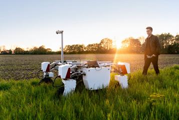
Since the last Journal, we have passed out two large class groups from Derby in June, and Glasgow in July, on our PWI S&C Refurbishment Course. Meeting people and discussing the “whys and wherefores” of what happens to S&C has been a pleasure and we are never surprised by new initiatives and insights from all over the place. I mentioned in July that we need to understand more about forces in S&C and I thought I would share with you one of our training slides which shows the extent of extreme lateral forces. We also talk about the concept of “virtual” transitions which relate to the movement of rail vehicles as they move from straight to curved track (image 1).
The great advantage of coming along to PWI training courses is meeting a wide range of people from different companies, from new graduates to people who have experience of many aspects of rail infrastructure. In S&C, few people may be aware of the tandem use of multi-purpose stoneblowers to correct vertical and horizontal alignment. I am indebted to Neil Wightman of Network Rail who following his attendance on our Module 1 in April, sent
us these photographs of MPSB’s working in tandem at Shields Jn in Glasgow. They were working on a concrete bearer crossover and I gather they had great success (images 2 & 3).
HERITAGE RAIL
We have been working with the Heritage Railway Sector in recent months and this started with a presentation at the PWI Technical Board by Stephen Clark, Permanent Way Engineer, from our Corporate Member, the Gloucestershire and Warwickshire Steam Railway. We held a workshop on 14 June which included presentations from ORR and HMRI and a training taster by PWI trainer, Roy Hickman. Matt Gillen of ORR talked about the technical standards aspects, and Steve Turner gave an insight into safety including track issues in tunnels. There are 220 heritage railways in the UK, so there is a great potential for the PWI to assist where we can through training and knowledge sharing. We have already had six engineers attending our track engineering diploma course and they all found it immensely useful! (Image 4).
REFLECTION
I mentioned in the last Journal that we have started reaping the benefits of normal face to face contact and the highlight of the Summer was Rail Live at Quinton Rail Technology Centre in Warwickshire.
 Counter TECHNICAL DIRECTOR technicaldirector@
thepwi.org
Brian
4
Our stand was in a great position, and we connected with many of our grass root members and recruited a few more. The weather was very warm, and this encouraged attendance. The new PWI tote bags with our new iron logo were handed out, so if you see them, you will know where they came from. Great work from Michelle and Kerrie.
It was good to present our new links with universities through the JBM to the face-to-face Section Secretaries meeting. The JBM have now changed their policy for Civil Engineering teaching in the UK and insist that all universities include transport engineering both highway and railway. There are two reasons for this: firstly, many graduates work in the transport sector which has a skill shortage. Secondly, transport is the industrial sector with the highest carbon emissions and the challenge is to create transport infrastructure that reduces carbon emissions from travel.

We are working on updating our textbooks and we will be releasing a new version of S&C Design in 2022 with the principal editor being Bob Langford. Also look out for some of the updated green and blue guides which Andy Steele is working on at present and will appear in the technical hub.

And finally, the usual track conundrum!


Peter Stanton, PWI Electrification Trainer, has posed a question. This chair and stone sleeper was found in King’s Langley old rail yard and is in a local museum. Can anyone suggest where it came from and how it was used? (Image 5).

 Image 1: Excerpt from PWI training course: Steering forces through points
Image 3: Multipurpose stoneblowers working in tandem at Shields Jn Glasgow (Photo courtesy Neil Wightman)
Image 4: Track layout on a heritage railway (Photo courtesy Gloucestershire Warwickshire Steam Railway)
Image 5: A rail chair found in a Hertfordshire Museum
Image 1: Excerpt from PWI training course: Steering forces through points
Image 3: Multipurpose stoneblowers working in tandem at Shields Jn Glasgow (Photo courtesy Neil Wightman)
Image 4: Track layout on a heritage railway (Photo courtesy Gloucestershire Warwickshire Steam Railway)
Image 5: A rail chair found in a Hertfordshire Museum
5
Image 2: Multipurpose stoneblowers working in tandem at Shields Jn Glasgow (Photo courtesy Neil Wightman)
THE WIDER WORLD OF
Engineering
OUT AND ABOUT – AT LAST!
The PWI had a good Summer! Presence at Rail Live in June and RailtexInfrarail in September enabled our Presidents and executive team to meet members and potential members face-to-face for the first time since February 2020. We’re very much looking forward to meeting friends old and new at our October Hit the North seminar in Manchester, and again at our Plant and Machinery event in Newcastle on 24 November: I hope to see you there! As Autumn progresses, some Sections are moving meetings to face-toface format, and I know many members relish the prospect of the informal socialising that’s very difficult in an online environment.
That said, we understand the continued Covid-19 threat and will carefully follow government guidance. Our online meeting platform and support will remain available for Sections that maintain virtual meetings. Remembering the upsides of the online environment, we intend to provide a programme of regular online technical meetings, additional to those organised by local Sections. This national programme is being pulled together by the PWI’s central team and will be advertised alongside local meetings. Wherever you are, there’ll be regular opportunities to enhance your continuing professional development! And if you miss a presentation, you can always catch up with the recorded version via the PWI website.
This is Engineering Day (TiE) 3 November 2021
Led by the Royal Academy of Engineering (RAEng)
What will a net zero world look like in 2050, a world that has been shaped by engineers to mitigate the effects of climate change and help us live a more sustainable life?

6
THE WIDER WORLD OF ENGINEERING…

Before turning to more domestic PWI matters it’s good to look at what’s going on in the wider engineering world, particularly in the run up to the COP26 UN climate change conference in Glasgow from 31 October to 12 November.
• This is Engineering Day (TiE) on 3 November, led by the Royal Academy of Engineering (RAEng) but involving all engineering institutions, will raise the profile of engineering and ask, “What will a net zero world look like in 2050, a world that has been shaped by engineers to mitigate the effects of climate change and help us live a more sustainable life?” See www. thisisengineering.org.uk/latest/this-is-engineering-day/ and please consider how you could support its objectives.
• TiE is followed closely by Tomorrow’s Engineers Week (TEW) from 8-12 November. TEW will feature young engineers and technicians working to achieve net zero. See www.tomorrowsengineers.org.uk/tomorrow-sengineers-week and, if you or a colleague are working in this field, please consider getting involved.
• Professional Engineering Committee (the leaders of all the UK’s engineering institutions) is setting up an Early Career Engineers PEC Group, to bring the views and experience of early career engineers to bear more forcefully on the UK’s engineering establishment. The Group will be hosted by RAEng and I am looking for two volunteers to represent the PWI on it. If you’re interested in the role, please contact me: stephen.barber@thepwi.org
• Safer Complex Systems is a 5-year mission launched in 2019 to improve the safety of complex infrastructure systems globally, led by Engineering X, an international collaboration bringing together some of the world’s leading problem-solvers. Work to date can be accessed via RAEng at www.raeng. org.uk/global/international-partnerships/engineering-x/safer-complexsystems Whilst air transport is mentioned in the work done so far, there is little reference to rail transport, a puzzling omission given our industry’s long experience of complexity. There certainly looks to be scope for more engagement and learning here.
PWI PEOPLE CHANGES
Luke Goude joined the marketing team in July in a fulltime role, to support us in growing our market presence. Some of you will have met Luke on the PWI stand at Railtex-Infrarail and we welcome him to the team. Though not from a railway background, Luke brims with enthusiasm and is taking every opportunity to learn about railway engineering and our industry: please don’t miss an opportunity to tell him what’s good (and not so good) about our industry.
In September, Past President Joan Heery took up a part time role as our Membership Director, in addition to her voluntary leadership of the PWI’s Decarbonisation and Climate Change Adaptation Advisory Committee. With the objective of growing our membership within railway engineering, Joan is refreshing the relationships she forged during her Presidency and strengthening the PWI’s links with the world of research and education. In the latter task she’ll work with our new NonExecutive Board Member, Professor William Powrie of Southampton University and the RAEng, who brings unrivalled knowledge in those fields.
At the end of September, we bid farewell to Andy Packham, standing down from his Technical Manager role - though not from PWI membership! I thank Andy for the herculean efforts he’s made to secure first class technical content for our Journal and for our seminars. In delivering joint international seminars Andy’s welldeveloped organising skills have won the PWI much respect from the other engineering institutions involved: delivering to time and budget is a skill he’s obviously not lost, and I wish him well for the future! Andy’s role will, from November, be filled by Mike Barlow, late of Transport for London. Mike started work with London Underground some years ago and has a career’s worth of design, renewal, project, maintenance, and engineering experience. I had the privilege of working with Mike at TfL and look forward to repeating the experience at the PWI.
SOME TALES OF WOE...
Despite much care in contractor selection and huge efforts from the Operations and Marketing teams, the long-anticipated renewal of the PWI’s website and customer relationship management system remains incomplete. Whilst the position is recoverable and our investment is not lost, for reasons beyond the PWI’s control it is doubtful that our original supplier will be able to complete the project. As I write in mid-September, we are considering alternative suppliers to complete the work, and interim solutions to allow our members to access the phenomenal work that has been completed on the new website. By the time you read this I hope to have made progress on both these fronts. In the meantime, I can only call on your patience and goodwill.
Embarrassment too with the PWI Practical Trackwork Challenge (PTC) where I reluctantly concluded that the October 2021 events should be deferred to 2022. Unfortunately, and late in the day, we found that we could not undertake the planned work in October at a tolerable level of operational risk. That decision, following a formal call for corporate member support, was difficult but it remains my strong view that a degree of embarrassment is preferrable to proceeding with work against a background of unmitigated technical and logistical risk. I thank the PWI team, and our heritage railway hosts for their considerable efforts to date, and I apologise again to those we’ve disappointed and inconvenienced.
To conclude on a positive note, I’m confident that robust arrangements will be in place for a PTC event in Spring 2022 and I’m very much looking forward to it.
Stephen Barber CEO Permanent Way Institution

7
THE PWI’S CLIMATE CHANGE & DECARBONISATION COMMITTEE

In the July Journal, I authored an article discussing the activities of the recently formed PWI Climate Change and Decarbonisation Committee. It is the intent going forward to provide a short summary update on the activities of the Committee alongside a comprehensive article within each Journal on some aspect of the subject matter to inform, educate and spark debate.
Within this Journal, Dr Rossa Donovan, Network Rail’s Head of Environment and Sustainability has penned an article on the actions the Rail industry needs to take to decarbonise, highlighting the scale of the problems we face in achieving net zero carbon and how the PWI and its membership can contribute to these objectives. I have no doubt you will find the article informative and thought provoking.
The latest Committee meeting took place virtually on the 27 July and we looked at progress from a tactical and strategic perspective. As an organisation, the PWI were pleased to report they had researched several organisations who could help them understand their carbon footprint and had made a decision to engage with an organisation called Ethical Nation. They specialise in helping SMEs understand their existing carbon footprint and then assist in developing plans to reduce this to zero.
As Chair, I had also made contact with Alexander Burrows at the Birmingham Centre for Railway Research and Innovation and extended an invitation for a suitable representative from this organisation to join the Committee which they were delighted to accept. We will therefore be welcoming a new member to the Committee in the autumn. The Manchester & Liverpool Section are hosting a technical conference in Spring 2022 on the subject of the Climate Emergency, and members of the Committee offered their thoughts on possible speakers and content.
You will have observed in the July Journal there was a significant article on the PWI becoming a member of the JBM, which is very important to us as a PEI. The JBM have the intent of organising a working group on climate change and decarbonisation as this is a critical element of university education for the current and next generation of engineers. They have requested representation from each of the PEIs to form part of the working group and the Committee shared initial thoughts on this.
As part of our education and improving our knowledge on the subject matter, we received a presentation from Dr Kim Yates from Mott McDonald who gave a comprehensive account of the actions this global consultancy have taken to become carbon neutral by 2020 and achieve net zero by 2040.
The Committee recognise there is still work to do in fully understanding our purpose and what success in this area looks like for the PWI, and we have started a piece of work to look at this. I will report back to the membership in the coming months.
Outwith the actions of the committee we are all watching with interest to see what happens at COP26 in November.
Joan Heery, Chair of the Advisory Committee on Climate Change & Decarbonisation Past President

8
We have a period of great opportunity
Nick Millington PRESIDENT Permanent Way Institution
I’d like to thank the very many people who have welcomed me to the role of President of the PWI over the last few weeks. It’s a privilege to hold the position and credit should go to John Edgely for his hard work over the last 12 months.
Since March, I have been undertaking safety critical work visits to front line rail maintenance, operations or projects work all over the country (for those of you who would like to see them, follow me on LinkedIn where I regularly post short films).


At the start, the trains I travelled on were really quiet. Stations were soulless and city centres eerily quiet. However, railway colleagues have put in a sterling effort: delivering projects, maintaining the railway, keeping freight corridors open, crewing trains etc. The railway industry has a lot to be proud of but delivering a punctual and high performing railway through a pandemic whilst delivering 25% of the UK construction turnover in parallel must be one of them! As lockdowns have lifted, I have observed trains getting busier and city centres coming out of hibernation. Even the PWI AGM in July was a face-to-face affair, and coupled with attending Rail Live, it has been great to see and speak to so many colleagues.
We should also pay tribute to colleagues in the NHS who have not only dealt with the pandemic under very difficult circumstances, they have mobilised a very swift COVID vaccination programme that has reduced societal risk and returned our freedoms. Face-to-face contact is vitally important, as is undertaking safety visits and conversations with your teams. The PWI has a busy calendar of meetings this Autumn and Winter. So I would call on all members to redouble efforts to get out as much as possible now that lockdowns have lifted (in the UK) and attend your local PWI section meetings, the larger conferences, and why not tie a safety tour into your plan too. Better still, why not leave the car at home and support the rail industry by using the train! I am going to visit as many of the local sections and attend as many conferences as possible this year, so will see as many of you as I can.
In my previous introductory note as incoming PWI President, I made it very clear that I wanted to muster the collective intellect, will and stakeholder network of the PWI membership to drive a renewed focus on safety risk reduction. Nine railway colleagues have lost their lives over the last three years, all preventable. Many more have been seriously injured: high voltage electricity, being crushed by large plant, road vehicle accidents being amongst the most prominent risks. And others have had some very near misses with moving trains… I am 100% confident that we can focus more on preventing these types of accidents, and in doing so we will save lives and reduce injuries. For example: In Network Rail, unassisted lookout working has been virtually eliminated over the last 24 months, and trackworker near misses (with moving trains) have dropped by 70% over the same time. However, over the last 15 months, we have had 87 high potential safety events with on track plant (OTP) across the railway network – many of these could have been prevented, a key common factor being risk reduction through better planning coupled with improved assurance of safe delivery.
I want every PWI member to play a more active and assertive role, not only spotting safety risks, but decisively eliminating or reducing these risks. Make a sport of it! Do your meeting agendas have an agenda item on this topic? As leaders, do you role model this style of risk reduction openly? How many behavioural close calls have you accumulated resulting in risk reduction? How many safety tours have you and your teams completed where tangible risk reducing actions have been delivered following your visit? In terms of safety leadership, the PWI is placed well with the membership being made up from Clients, Designers, Principal Designers, Principal Contractors and Contractors amongst others.
Looking forward, we have a period of great opportunity. The PWI, now a Joint Board of Moderators (JBM) member, offers great training and professional development certification. In terms of railway infrastructure, OHLE joining PWay Engineering increase our capability and our collective ability to grow and share knowledge. Rail travel, as a form of low carbon transportation, has an obvious strength to exploit and the Williams Shapps report issued in May ’21 heralds a new era of ‘Great British Railways’ from 2024 onwards.
It is all in our gift…
Connect with Nick on LinkedIn
9
Decarbonising the rail industry
 AUTHOR: Dr Rossa Donovan
Dr Rossa Donovan is an environmental scientist with over 30 years of experience in environmental sustainability gained from academic research and as a practitioner working in the rail, highways and commercial development sectors. As Head of Environment & Sustainability for Network Rail, Rossa coauthored Network Rail’s recently published 30-year environmental sustainability strategy which includes targets and roadmaps for net-zero carbon, air quality, biodiversity net gain, climate change adaptation and minimising waste and efficient use of materials. He is currently working as a Principal Environment & Sustainability Specialist in Network Rail working with rail industry experts to help deliver the strategy. Rossa is a chartered ecologist and is passionate about helping the rail industry to become even more sustainable and minimise the impact that it has on the environment.
INTRODUCTION
Climate change, the term used to describe anthropogenically induced global heating, has been described as the ‘Biggest Threat Modern Humans Have Ever Faced’1. There is a growing body of scientific evidence that predicts that climate change, if left unchecked, will radically alter life on earth as we know it. Currently, the global average surface temperature is approximately 1°C warmer than pre-industrial levels and as a result we are already experiencing more extreme weather events and disrupted weather patterns, including increased rainfall and flooding, higher temperatures and more droughts. By the end of this century, we could see the global average surface temperature rise to approximately 4°C and the Met Office predicts2 that by 2070 we can expect summers to be up to 6°C warmer, winters to be up to 30% wetter and rainfall intensity to increase by up to 25%.
While scientists have been talking about climate change for nearly 40 years, it was the climate activists Greta Thunberg and Extinction Rebellion along with Sir David Attenborough’s documentary ‘Climate Change: The Facts’ that together have successfully managed to bring the issue of climate change and biodiversity loss into the public consciousness and to the attention of our politicians. In response to this, in May 2019, the UK Government became the first major economy in the world to declare an Environment and Climate Emergency and promptly set legally binding targets to reach net zero carbon by 2050.
Even before the UK Government declared an environment and climate emergency, experts across the rail industry have been working on the issues of how to decarbonise the railway to reach net zero and how to adapt to the impacts of climate change that will inevitably happen on the way to net zero. This article looks at decarbonisation rather than climate change adaptation. It explores the actions that the rail industry needs to take to decarbonise, highlights the scale of the problems we face in achieving net zero carbon, and how the PWI and its membership can contribute to these objectives.
GREENHOUSE GAS EMISSIONS IN THE RAIL INDUSTRY
There are many different types of greenhouse gas which are emitted by the rail industry, all of which have different global warming potentials. For example, methane is a greenhouse gas which has 21 times greater global warming potential than carbon dioxide over 100 years, and sulphur hexafluoride, which is used in electrical switchgear and can sometimes escape into the atmosphere, is estimated to be approximately 24,000 times more powerful than carbon dioxide. However, the volumes that are released vary
significantly therefore it is helpful to describe greenhouse gas emissions as carbon dioxide equivalents, or CO2e, and because of this greenhouse gas emissions are widely referred to as carbon emissions. The main types of greenhouse gas that are emitted by the rail industry are as follows:
• Carbon dioxide
• Methane
• Nitrous oxide
• Hydrofluorocarbon gases
• Perfluorocarbon gases
• Sulphur hexafluoride
While rail is already recognised as one of the lowest-carbon forms of mass transport, the RSSB has estimated that as an industry we emit approximately 9.5 million tonnes of carbon-dioxide equivalents (CO2e) each year both directly through our own activities or indirectly through our value chain3. To place things into context, DfT analysis, which differed from the RSSB study in that it only considered direct emissions (ie, does not include embodied carbon or supply chain emissions), has calculated that in 2019 transport in the UK as a whole was responsible for 122 MtCO2e emissions to the atmosphere, or approximately 27% of the UK’s domestic greenhouse gas emissions. Of those 122 million tonnes, 87% was produced by the road sector, and 1.4% was produced by the rail sector4
Even though rail’s carbon emissions are much smaller than those from road transport or aviation, the rail industry has an important role to play in supporting the Government’s net zero carbon target, not only by decarbonising our own activities, but also through modal shift, ie, attracting more passengers and freight onto the railway, away from the more polluting road and aviation sectors.
UNDERSTANDING RAIL’S GREENHOUSE GAS (GHG) EMISSIONS
The GHG Protocol categorises GHG emissions into three scopes as shown in table 1. Categorising emissions in this way helps organisations understand where their direct and indirect emissions are coming from and provides a framework which can be used to evaluate the quantum of emissions coming from each activity.
Network Rail, the biggest emitter of carbon emissions in the rail industry due to its role as the major infrastructure operator in GB, has carried out an analysis of its scope 1, 2 and 3 emissions5 The analysis estimated that scope 1 & 2 emissions accounted for approximately 3% of its global footprint, with the remaining 97% sitting within scope 3.
10
The analysis revealed that the largest contributors to scope 3 emissions by far were from:
• Use of Sold Products – in this instance, the use of sold products means the use of the rail network that Network Rail owns and operates. The users of that network are the train operators that run their trains on Network Rail’s tracks. Therefore, this category measures the emissions from running those trains. These emissions are categorised as indirect because Network Rail does not have control over the fuel used to power those trains. As traction electricity comes from nuclear power generation, and is considered to be zero carbon, carbon emissions from the use of sold products, which is estimated to be 25% of all emissions, relates to the use of diesel trains on Network Rail’s infrastructure.
• Purchased Goods and Services – estimated emissions from the suppliers of the goods and services that Network Rail purchases.
• Capital Goods – estimated emissions from contractors and suppliers who carry out Network Rail’s capital works and infrastructure development.
It is important, at this point, to understand the uncertainties that are attached to some of the scope 3 emissions estimates. While we can calculate, with some certainty, the carbon emissions generated by diesel trains, accurately calculating carbon emissions from capital goods is more problematic. While the analyses carried out by Network Rail and the Rail Safety Standards Board follow the methodology recommended by the Greenhouse Gas Protocol, the methodology allows certain assumptions to be made to arrive at an estimate of carbon emissions for capital goods. Because it is currently very difficult to accurately calculate the carbon emitted from the manufacture and construction of rail infrastructure, the methodology allows a carbon factor to be applied to the amount of capital spent on procuring, constructing and commissioning that infrastructure. As there is no carbon factor specifically for track renewals, the value for fabricated metals was used as a surrogate, and because metal fabrication is likely to be more energy (and therefore carbon) intensive than track renewals, it is possible that the embodied carbon figures cited in these analyses are over-estimates. The same is probably true for the calculation of carbon emissions from the goods and services category and much more work is required to refine the estimates for both categories. However, this is the best data we have at present and both categories are still likely to be significant emission sources in the rail industry.
The study estimated that the total carbon footprint for the UK rail industry for 2019/2020 was approximately 9.5 MtCO2e and that embodied carbon and diesel/gas oil accounted for the majority of those emissions. The RSSB study reports traction electricity as the third biggest emissions source for the industry accounting for approximately 10% of overall emissions. This differs from the Network Rail analysis which used a market-based approach
to measure traction electricity emissions - because traction electricity supplied by Network Rail to the train operators comes from EDF’s Blue Tariff, where electricity is sourced from nuclear power generation, following a market-based approach it is counted as zero emissions at the point of generation. The RSSB study, however, uses a location-based approach following BEIS6 guidance, which uses the overall carbon mix of the national electricity grid for accounting purposes, the reason being that although traction electricity is sourced from nuclear generation, the amount of power consumed is not additional in respect of developing new renewable generation, merely part of the existing grid carbon mix.
WHAT ACTION DOES THE RAIL INDUSTRY NEED TO TAKE TO DECARBONISE?
The preceding section clearly illustrates that quantifying carbon emissions is not an easy process, and this is especially the case for an industry as large and complex as the rail industry, and unfortunately decarbonising the rail industry will not be straightforward either. Colleagues have often asked me why, when rail is already recognised as one of the lowest-carbon forms of mass transport, do we need to decarbonise at all?

While road transport currently produces the lion’s share of transportderived carbon emissions, with rapid advances being made in battery, electric and hydrogen vehicle technology, the road sector is likely to decarbonise quickly. It is estimated that by 2035 46% of vehicles on our roads will have zero tailpipe emissions7 and that figure is likely to rise exponentially thereafter as the ban on the sale of new internal combustion engine cars and vans comes into force in 2035. If rail is to retain its title of one of the lowest carbon forms of mass transport in the future, and thus remain an attractive proposition for sustainable long-distance travel, it will need to decarbonise as quickly as possible.
Doing nothing is not an option and waiting for technology to solve all our problems is not a sensible option either. While 2050 seems a long way off, in reality it doesn’t leave us much time to make the changes that are required to decarbonise the railway. For example, new technologies, such as hydrogen trains, take time to develop and perfect, and electrification of large areas of the rail network will take time to achieve, and these are only two elements of the many things that we need to do to achieve net zero carbon.
Another question I am often asked is why do we have to act now, why can’t we leave it until later? This might seem like an attractive proposition, as it would give companies more time to plan and implement their decarbonisation objectives, but the simple fact is that the half-life of atmospheric carbon dioxide is nearly 100 years, therefore the longer we wait to act, the greater the cumulative emissions that will build up in the atmosphere and the worse the impact will be on global temperatures.
The Williams-Shapps review8, published in May 2021, sets out ambitions for a cleaner, greener rail network highlighting the need
Table 1: Definition of GHG protocol scopes.
Figure 1: Summary of the technical abilities of the three technologies considered as part of the TDNS9

11
for decarbonisation, greater biodiversity and improvements in air quality in towns and cities to ensure rail is the backbone of a cleaner, greener public transport network. This has been followed by the DfT’s long awaited Decarbonising Transport plan7 which sets out the steps that the UK needs to take to decarbonise its transport system. For Rail the priorities are: removing diesel-only trains from the network by 2040 (Scotland has already set a target of 2035 for removing diesel-only trains from Scotland’s Railway); electrification of more miles of track; increased use of battery and hydrogen technology; increased modal shift of both passengers and freight from road and air to rail; improve rail journey connectivity with walking, cycling and other modes of public transport; and incentivising low carbon traction options for freight.
In 2020, Network Rail committed to achieving net zero carbon by 2050 – Scotland’s Railway had already committed to net zero by 2045. Network Rail’s low emissions strategy5 uses sciencebased targets to set out a pathway to net zero based on the more stringent 1.5°C global warming scenario, making it the first railway infrastructure operator in the world to set SBTs to this more stringent scenario.
TRACTION DIESEL
The Traction Decarbonisation Network Strategy – Interim Programme Business Case9, also published in 2020, brought experts together from across the industry to consider how to decarbonise traction energy. This review was carried out in response to Jo Johnson’s, then Secretary of State for Transport, challenge to the rail industry to remove diesel-only trains from the rail network by 2040. The report considers where overhead electrification, hydrogen or battery trains might best be deployed to decarbonise the railway as summarised in figure 1.
The TDNS recommended that for the 15,400 single track kilometres (STK) of unelectrified track, approximately 11,700 STKs of electrification was required for high-speed long-distance passenger and freight services; hydrogen trains should be deployed over approximately 900 STK; battery trains should be deployed over approximately 400 STK. For the remaining 2,400 STK, the choice of a single technology is not immediately clear but further analysis suggested this would increase electrification by around 1,300 STKs and battery and hydrogen both by the equivalent distances of a further 400 STKs. This would result in 96% of passenger unit kilometres operated using electric traction, and the remaining 4% using hydrogen or battery. For freight, around 90% of train kilometres could be operated using electric traction, with the remaining 10% requiring the use of diesel or an alternative means of traction.
Clearly, from the analysis carried out in the TDNS9, a large-scale electrification programme will be a priority in the short-medium timescale to help decarbonise traction power requirements. There is much debate around whether we should use battery or hydrogen trains for non-electrified parts of the network. Battery technology is advancing rapidly while green hydrogen production is both expensive and not widely available and its transmission and storage remain a problem, although the future of ammonia as a hydrogen carrier looks promising with well-developed knowledge and infrastructures in terms of transport and storage.
TRACTION AND NON-TRACTION ELECTRICITY
The best way to decarbonise the rail industry’s electricity needs is to ensure that the supply source is 100% renewable and additional to that currently fed into the national grid. This can be achieved either by building new renewable energy generation assets and feeding them directly into the electrified network or, where this is not possible due to space or capacity constraints, to enter into Power Purchase Agreements with renewable energy generation companies to generate additional renewable energy to meet the needs of the railway. The rail industry is already the largest consumer of electricity in the UK, and as we electrify more kilometres of track we will consume more electricity, therefore it is not a simple case of just buying more renewable energy, but we will also need to use energy more efficiently as well so that we reduce our demand as much as possible, given that we will not be the only ones trying to switch our energy supplies to renewable sources.
Electricity powered traction is likely to be the best option in most cases, being the lowest carbon option currently available emitting 0.33 kgCO2e/kWh compared to diesel which is 0.84 kgCO2e/kWh10, this figure is predicted to drop further as the grid decarbonises to as low as 0.08 kgCO2e/kWh by 20403. However, factors such as economics, disruption to service, destruction of biodiversity and whole life carbon implications of electrification should be considered on a case-by-case basis to ensure that an appropriate level of train service can be delivered for the lowest whole-life carbon, environmental and economic cost.
OTHER FUELS
Apart from traction diesel and electricity, the rail industry uses a range of other fuels such as natural gas, LPG and gas oil to heat our workplaces and power our plant. It is estimated that natural gas use alone accounts for 99 ktCO2e of carbon emissions per annum and gas oil a further 12 ktCO2e of carbon emissions per annum3 While these are fairly small numbers compared to the total global emissions of the rail sector, they are still a significant part of the carbon equation and therefore the industry needs to transition to lower or zero carbon alternatives if we are to achieve net zero.
EMBODIED CARBON
RSSB’s report3 noted that while the Traction Decarbonisation Network Strategy 9 had put forward ways to decarbonise traction emissions, there was no equivalent industry wide initiative to look at embodied carbon. Embodied carbon is the carbon dioxide or other greenhouse gas emissions associated with the manufacture or use of a product or service. For construction products, this means the carbon dioxide or greenhouse gas emissions associated with extraction, manufacturing, transporting, installing, maintaining and disposing of construction materials and products. The majority of embodied carbon contained in a construction product is the carbon emissions produced from the use of fossil fuels in extraction and manufacturing of construction materials and as a result of process emissions from manufacturing11
For example, the production of concrete or steel, or any other material for that matter, can be considered to contain the amount of carbon dioxide or greenhouse gas released into the atmosphere by the energy source that was used to produce it. So, a piece of rail produced using a non-renewable source of energy, such as gas, or even electricity taken from the national grid, will have significantly higher embodied carbon than a piece of rail produced using directwired renewable energy sources such as solar or wind.
The term whole life carbon is used to describe both the embodied carbon and operational carbon of a building or product. PAS208012 –the global standard for managing carbon in infrastructure – provides a systematic way for managing whole life carbon in infrastructure delivery and requires asset owners, designers, constructors and suppliers to work together to provide the lowest carbon solution for new infrastructure. Taking a whole life carbon approach is essential for understanding and minimising the carbon implications of a project through all infrastructure delivery work stages as shown in figure 2.
Whole life carbon isn’t just relevant to rail infrastructure and the approach should be used for all assets, products and processes that are utilised by the railway. RSSB’s DECARB report3, while it managed to estimate embodied carbon contained in rolling stock, noted the lack of available data to make an accurate assessment. It also noted the preference for buying new rolling stock as opposed to refurbishing old rolling stock which is then scrapped. This does not make sense from a carbon perspective and adopting circular economy thinking in the production of the railway’s rolling stock is required.
This also applies to virtually every product or process that is used to build and run the railway. Adopting circular economy principles, ie, choosing products that have low or zero embodied carbon, that use minimal virgin resources, can be used for a primary function and then reused for a secondary purpose before being recycled into a new product, will reduce the carbon emissions produced by the Rail Industry and its supply chain.
12
Figure 2: Summary of how whole life carbon emissions can be managed by integrating different carbon management process components into existing infrastructure work stages. (Source: PAS2080:201612)

FLEET
The Rail Industry relies on a fleet of road vehicles and plant to construct, operate and maintain the railway. Network Rail alone has a fleet of approximately 8,500 cars, vans and HGVs which are essential for running and maintaining the railway and many of these use either petrol or diesel as a source of fuel, although numbers of hybrid and purely electric vehicles are increasing. In 2020, Network Rail published targets to transition its car fleet to 25% ultra-low emission vehicles (ULEV) by 2022 and 100% by 2030, with a commitment to have all vehicles in its fleet to be ULEV by 20355 The Office for Zero Emissions Vehicles (OZEV) has since published more ambitious targets for all government departments and armslength bodies (which includes Network Rail) to transition all cars, vans and 4x4 fleets to 25% ULEV by 2022 and 100% electric vehicles by 2027. This will certainly be a challenge, not only because of the additional cost that will be required to replace vehicles and end lease agreements early, but also because of the associated charging infrastructure which will need to be installed to enable the cars to be charged. While these targets don’t apply to the rest of the industry, the decarbonisation of our collective road fleet will play an important part in helping the industry reach net zero, and the sooner this is achieved the better.
CLOSING REMARKS
Electrification of large parts of the network will be key to driving down our traction carbon emissions and should be a priority over the short-medium term. Other technological fixes such as producing or procuring renewable energy and transitioning to zero emission fleet vehicles will also be important and the technology to do this is already available for some vehicles and advancing rapidly.
Another important challenge for the rail industry, and highly relevant to the PWI and its membership, is how we reduce the embodied carbon contained in our infrastructure, rolling stock and the goods and services that we procure to keep the railway running. While inroads are already being made into the production of lower-carbon concrete and steel, much more needs to be done to find low or zerocarbon alternatives to the materials and products that are normally specified.
In addition, the methodologies used to calculate embodied carbon in our capital goods and our goods and services need to be improved further to enable more accurate estimates to be made. This will require collaborative working across the industry and its supply chains and considerable research and innovation to reduce embodied carbon to a minimum. Just as important will be the management of carbon during infrastructure delivery work stages and adopting of whole life carbon assessments as best practice will help deliver the low or zero carbon solutions that we need.
REFERENCES
1. UN Security Council. 2021. Press Release SC14445 – 23/02/21. Webpage: https://www.un.org/press/en/2021/sc14445.doc.htm Accessed: 03/08.2021.
2 Met Office. Climate Change in the UK. Webpage: https://www. metoffice.org.uk/weather/climate-change/climate-change-in-the-uk Accessed 05/08/21.
3 Watson, E. & Broom, C., 2021. T1197: DECARB: Carbon Measurements. Rail Safety Standards Board.
4 DfT analysis based on: BEIS, Final UK greenhouse gas emissions national statistics 1990-2019, 2021. Webpage: https://www.gov.uk/ statistics/final-uk-greenhouse-gas-emissions-national-statistics1990-to-2019. Accessed 11/08/21.
5. Network Rail. 2020. Our Ambition For A Low Emission Railway.
6. BEIS, 2019. 2019 UK Greenhouse Gas Emissions, Provisional Figures.
7. Department for Transport. 2021. Decarbonising Transport – A Better Greener Britain. Department for Transport.
8. Williams, K. & Shapps, G. 2021. Great British Railways: The Williams-Shapps Plan for Rail.
9. Network Rail. 2020. Traction Decarbonisation Network Strategy –Interim Programme Business Case.
10. Rail Industry Decarbonisation Taskforce. 2019. Final Report to the Minister for Rail.
11. Cao, C. 2017. Chapter 21. Sustainability and Life Assessment of High Strength Natural Fibre Composites in Construction. In. Advanced High Strength Natural Fibre Composites in Construction, Pp. 529-544.
12. PAS2080:2016 – Carbon Management in Infrastructure. Construction Leadership Council & The Green Construction Board.
13
Enabling data-driven predictive maintenance for S&C through Digital Twin models and condition monitoring systems
 AUTHOR: Nikhil Pillai
Nikhil Pillai is currently reading for a PhD in Railway Systems Engineering at BCRRE, University of Birmingham. For his PhD, he is developing numerical models of Train-S&C interactions to enable intelligent decisions for structural health monitoring. Before joining the university, Nikhil trained as a Mechanical Engineer at Knorr-Bremse Rail Systems (UK), where he worked on projects including the product development, testing of railway mechatronic systems and structural analysis of platform structures. He previously read for a degree in Mechanical Engineering at Cardiff University and graduated with First Class Honours. Nikhil was the West Midlands Chair for Young Rail Professionals (YRP) and is keen on industrial engagement. He is open to being contacted for industrial collaboration.

ABSTRACT
AUTHOR: Dr Jou-Yi Shih
Dr Jou-Yi Shih is the founder of ZynaMic Engineering AB in Stockholm, a specialist railway consultancy for railway dynamics. She specialises in numerical simulation including Finite Element Analysis (FEA) and Multi-Body Simulation (MBS) and is well networked within academia and industry. Through her company, she provides her competencies on projects involving vehicle/track dynamics, ground-borne vibration, material mechanics (eg failure modelling), and vibration measurement for bridge, track, and railway S&C. She received her PhD from the Institute of Sound and Vibrations (ISVR) at the University of Southampton and worked earlier at Institute of Railway Research (IRR), University of Huddersfield and Birmingham Centre for Railway Research and Education (BCRRE).

With the advancement in digital technologies and smart manufacturing, solutions for continuously monitoring the condition of Switch and Crossing (S&C) rails are being investigated. Existing understanding of the physical principles of degradation and the mechanical interaction between trains and switches can help support decisions on predictive maintenance.
Therefore, models of train-turnout interactions have been developed to support key decisions for the maintenance of S&C. A combined modelling approach incorporating Multi-Body Simulation (MBS) and Finite Element (FE) analysis of train-turnout interactions has been proposed for establishing the locations susceptible to failure and determining sensor placement. In addition, an approach for calibrating the substructure dynamic behaviour between the MBS and FE models has been demonstrated. Results for the rail receptance and contact forces obtained for the FE model have been compared with the reference MBS model and show good agreement. In the end, perspectives on transforming numerical simulation models into Digital Twins and advanced manufacturing for smart and self-monitoring infrastructures have been shared, which will no doubt be topics of future work.
INTRODUCTION
AUTHOR: Professor Clive Roberts
Professor Clive Roberts is Head of the School of Engineering at the University of Birmingham and Director of the Birmingham Centre for Railway Research and Education. Clive leads a broad portfolio of research aimed at improving the performance of railway systems, including leading the UK Railway Research and Innovation Network (UKRRIN) - a £92M academia/industry collaboration. He is a member of the Advisory Board for the UK Railway Industry’s Technical Leadership Group and has contributed significantly to the 2020 UK Rail Technical Strategy. He works extensively with the railway industry and academia in Britain and overseas.
S&C accounts for just 4% of the total track mileage in the UK but attributes to over 20% of the maintenance and renewal budgets for Network Rail1. This is primarily due to the variation of the crosssectional geometry in the switch panel and the presence of a discontinuity during the transition from the wing rail to the crossing. This results in a higher amplitude of wheel-rail impact forces in S&C than in continuously running rails, resulting in a higher rate of deterioration.
Infrastructure managers have been trying to bring down the cost of maintenance for S&C. With the adoption of digital technologies, data-driven predictive maintenance has immense potential for increasing safety, preventing failures, increasing route availability and reducing long-term costs. Two of the main approaches to supporting predictive maintenance of S&C through the adoption of digital technologies are automated periodic inspection and continuous condition monitoring. Data-driven periodic inspection can be supported by equipment such as unmanned aerial vehicles (UAVs) and measurement trains. However, for safety-critical systems such as S&C, continuous condition monitoring will not only improve safety but also reduce costs attributed to both failure and inspection.
14
Currently, condition monitoring of S&C is limited to the analysis of electrical signals obtained from point machines. This approach can be used for monitoring switch opening and closure. However, this approach to condition monitoring has a limited potential for recognising the occurrence of faults away from the switch toe. Therefore, one proposed approach to gathering information about the structural health of S&C rails would be the installation of physical sensors on the permanent way itself.
There are certain challenges associated with the installation of physical sensors on infrastructure. Firstly, crucial locations on the S&C that are susceptible to failure would need to be identified. Secondly, the sensors would need to be installed to ensure that data from these crucial locations can be captured. Thirdly, the sensors would need to be robust enough to withstand the high dynamic forces associated with wheel-rail interaction. Physical sensors are already being used for monitoring the condition of structural assets such as bridges, where sensor measurements are passed to condition monitoring algorithms to obtain information about the state of health of the asset. However, harsh dynamic forces and vibrations encountered during vehicle-track interaction have made the installation of sensors on the permanent way more challenging.
For the identification of locations to monitor for failure, statistical data for failure from the infrastructure manager could be analysed. Previous inspection logs would help determine statistically significant locations that are vulnerable to failure as well as the forms of damage observed at such locations. However, where this data is not available or is challenging to acquire, numerical simulations are a potential alternative to predicting the locations prone to failure by employing formal engineering knowledge about asset degradation. Numerical simulations are powerful tools that can be used for modelling asset interactions.


Through the appropriate use of modelling approaches and knowledge from the fields of materials science, tribology, structural dynamics and mechanics, the physical interactions of the infrastructure with the rolling stock can be simulated to anticipate locations of failure. Currently, numerical simulations are also used in the rail industry to predict failure, such as the prediction of Wear and Rolling Contact Fatigue (RCF) through the Whole Life Rail Model (WLRM)2. The use of numerical simulation approaches for predicting the locations of failure as well as their magnitude is a topic of interest in academia and has been evaluated for S&C by the authors3
Research groups had previously employed a field experimentation approach to determine sensor placement at potential damage locations. It was concluded that it is unreliable to install multiple sensors and perform field experiments to determine sensor placement in harsh environments due to sensor failures, expensive site access charges and experimental setup times 4. As a potential solution, the authors have recognised that validated numerical simulations are a safe and reliable way to generate data to determine sensor placement.
The requirement of robustness for sensors in harsh railway environments is an important consideration in enabling their installation. Along with the advancements in digital technologies, there has also been an advancement in manufacturing for the construction of smart components. Additive manufacturing of metallic components is a subject of interest in the research community, which is being actively explored for the embedment of sensors into “smart” infrastructures. Previously more popular for polymers, metallic additive manufacturing is now an area of interest in the manufacturing industry and is predicted to witness adoption at a wider scale5
Moreover, the availability of data related to live traffic from the field enables the transformation of numerical models into Digital Twins for S&C, where the acquired live data could be fed into models to obtain useful information for planning S&C maintenance. Historically, modelling and structural analysis were only employed at the planning stage of a project, mostly for design verification but such models can now be optimised for usage in the asset operation stage.
These challenges are being investigated through a funded PhD by the first author under the supervision of the other authors. The scope of the project includes the development of numerical simulation models that can predict the key locations for the failure of railway switches as well as determine the placement of sensors on the infrastructure. In SECTION 2 of this article, a novel approach to modelling train-switch interactions for the aforementioned research interests has been explained. The results from the simulations have been discussed in SECTION 3. In SECTION 4, potential approaches to the incorporation of these models into Digital Twins to support predictive maintenance have been conveyed. In addition, topics such as the relationship between multi-physics simulations and
Figure 2: Bilinear RCF damage function2 for Rail grade R260. 15
Figure 1: Simulation approach whilst considering calibrated substructure dynamics.
Figure 3: Rail-sleeper connection in the FE model.
Figure 4: Connections between the different track layers of the MBS model.
sensor-based condition-monitoring systems along with perspectives on manufacturing smart rails embedded with sensors have been explored.
METHODOLOGY FOR MODELLING THE INTERACTION BETWEEN TRAINS AND RAILWAY SWITCHES

In a recently published article3, the authors had discussed that among the main numerical approaches for simulating train-track interactions, Multi-Body Simulations (MBS) and Finite Element (FE) analysis could be used to effectively model the detailed train dynamics and mechanical behaviour of the subsurface material respectively. In literature, the results from these simulation approaches have been used in degradation prediction models to predict damage locations as well as quantitative degradation. The results from the simulations have also been validated against field observations.
We have used the results from our evaluation of train-turnout modelling approaches for the development of a combined simulation approach that involves carrying out simulations using both MBS and the FEA methods. The proposed simulation approach, shown in figure 1, has been used for determining the locations along the length of switches that are susceptible to surface damage as well as the installation of sensors for detecting the development of faults at the predicted locations.
STEP 1: PREDICTION OF FAILURE-PRONE LOCATIONS BY POST-PROCESSING OUTPUTS FROM A VALIDATED MBS MODEL
The focus of this research has been on the initiation of surface damage, especially rolling contact fatigue (RCF) cracks, since they propagate further into the rail subsurface and lead to different failure mechanisms. Another reason for focusing on surface-initiated faults is the suggestion that surface wear and fracture are the main forms of damage in switches that have historically contributed the most to delays as well as maintenance and renewal costs1. For the calculation of surface damage, the wear number, Tγ, has been calculated from the summation of the creep forces and creepages in the longitudinal, lateral and rotary spin directions obtained from an MBS train-track interaction simulation. The wear number can be correlated to the wear and RCF occurrence according to the empirical linking of the bilinear RCF damage function to the wear number by Burstow 2, as shown in figure 2. Also, the critical values of Tγ are dependent on the rail material.
For Rail grade R260, a comparison of the Tγ values against field observations (figure 2) determined that values of Tγ less than 15 J/m would result in no damage. Values between 15 to 75 J/m would indicate locations prone to RCF. Values between 75 and 175 J/m would indicate a reduction in RCF and an increase in wear, and values greater than 175 J/m resulted in excessive wear, resulting in the removal of any surface initiated RCF cracks6. In contrast, excessive wear would potentially occur for R350HT rail steel only when Tγ>400 J/m 6

16
Simulations were carried out for the interaction between a passenger vehicle model7 and a railway switch model for the Swedish turnout layout of UIC60-760-1:148 whilst considering Rail grade R260 material. The wear number was calculated based on the outputs from the model developed for the S&C multi-body simulation9
STEP 2: DEVELOPMENT OF FE MODELS FOR THE TRACK AT FAILURE-PRONE LOCATIONS
Unlike MBS simulations, the material mechanics of the subsurface rail can be analysed through the FE approach. This information is crucial for the determination of sensor placement and other studies related to the subsurface rail.
As the consideration of detailed vehicle dynamics has often been ignored in FE modelling to improve computational efficiency3 , the use of combined MBS-FE simulations has been observed in literature to alleviate this. In this combined numerical simulation approach, crucial information from the train-turnout dynamic interaction is obtained from MBS simulations and exported to FE for further analysis.
A lack of compatibility between the track dynamics of MBS and FE models has been observed from the examples in literature3. This is important to consider, as the stiffness of the track is higher at locations where the rail is supported by the sleeper than it is where there is no support. Moreover, at supported sections, a turnout with softer pad support for the superstructure and softer bedding would allow for more vertical movement of the rails than when the support is stiffer. Therefore, the calibration of the track stiffness against the field or reference models would help ensure the validity of results for similar conditions.
To address this gap in the literature, a combined simulation approach has been used that involves the substitution of results for the movement of the vehicle obtained from the MBS model to the FE model whilst ensuring compatibility of the track models between the two approaches.
In the FE model, the stock rail was supported by a railpad, affixed on a baseplate, which was connected to a baseplate pad, placed on a sleeper, all lying on a ballast bed which was fixed to the ground, as shown in figure 3 and figure 5. The switch rail was directly mounted
to the baseplate (figure 5). However, in the MBS model, the rails are supported just by two layers, with the railpad connecting the rail and the sleepers following the ballast connecting the sleepers to the ground.
Therefore, to ensure compatibility between the two track models used in MBS and FE, the equivalent stiffness of the combination of railpad, baseplate and baseplate pad layers in FE (figure 3) was compared against the stiffness of the railpad layer in MBS (figure 4). Subsequently, the stiffness properties for the railpad, underbaseplate pad and ballast layers were obtained from Network Rail standards and used to calculate the equivalent elastic modulus for the materials at these layers.
Depending on the frequency range at which they contribute to resonance, the material damping behaviour for the pads and ballast were fine-tuned against the reference model. For this, the Rayleigh damping coefficients were calculated.
For the inclusion of the appropriate dynamic effects for the ballast layer, several proposals were explored. One solution explored the consideration of vertical and lateral spring-dashpot elements attached to the sleeper end surfaces to account for the ballast layer. Another explored the consideration of a solid ballast layer whilst converting stiffness and viscous damping used in MBS into the material properties of equivalent elastic modulus and Rayleigh damping to replicate the dynamic behaviour in FEA. The receptance from both the modelling approaches were obtained and compared.

STEP 3: CALIBRATION OF TRACK SUBSTRUCTURE BEHAVIOUR AND TRACK MODEL VALIDATION
On the derivation of the material properties, the rail receptance, ie deflection of the rail on the application of a unit load was compared between the MBS and FE models for the frequency range of interest. For components modelled using solid elements, ie the railpads, underbaseplate pads and ballast, sensitivity analysis for the damping loss factor was carried out for fine-tuning the damping behaviour with the reference. Analysis was also carried out using springdashpot elements to represent the ballast layer, where the values for the stiffness and the viscous damping could directly be divided by the number of nodes representing the interface surface.
Figure 5: 3D FE model assembly for rolling contact simulations.
17
Figure 6: Prediction of locations susceptible to high surface damage.
STEP 4: ROLLING CONTACT SIMULATIONS AND VALIDATION AGAINST THE REFERENCE.
Once the compatibility between the substructure behaviour of the MBS and FE models was ensured, Finite Element rolling contact simulations were carried out. The dynamic interaction between a single S1002 wheel passing over the stock and switch rails in the transition region of the switch panel (figure 5) was performed. Appropriate boundary interactions between the different layers of the track as well as the contact between the wheel and rail-head surfaces were ensured.
The results from the lateral and longitudinal movement of the wheel obtained from the MBS model used in STEP 1 were input as the variable boundary conditions for the wheel in FE. The FE model was validated by comparing the contact force results against the MBS reference model. Along with the validity of the surface contact results, it was also ensured that converged results were obtained for the mechanical behaviour of the subsurface rail elements.
DISCUSSION OF RESULTS: PREDICTION OF DAMAGE LOCATIONS
The locations susceptible to high railhead wear and surface-initiated RCF were determined from MBS simulations of train-turnout interactions. On the comparison of the influence of the passage of different wheelsets, it was observed that interaction of the switch with the leading wheelset would result in the highest surface damage. The result for the wear number, ‘Tγ’, obtained from the passage of the first wheelset of the two-bogie vehicle has been shown in figure 6.


High values for the Wear number were obtained at the location between 7 and 9 metres (m), where the wheel-rail contact patch transitions from the stock to the switch rail. Also, two-point contact was observed at this location. Contact point 2 (CP2) occurs between the wheel flange and the switch rail gauge corner. Contact point 1 is the point of contact between the wheel tread and the railhead, which was shown to move towards the rail gauge corner but later returns to its nominal position close to the railhead centre after stabilisation of the wheelset lateral movement. According to the bilinear RCF damage function (figure 2) by Burstow 2, the highest risk of surfaceinitiated RCF has been obtained between 9 and 9.5 m from the switch toe, where the wear number is close to 75 J/m.
DISCUSSION OF RESULTS: CALCULATION OF THE MATERIAL PROPERTIES AND VERIFICATION OF TRACK STIFFNESS
Figure 7: Compatibility of track dynamics between the MBS and FE models.
As shown in figure 7, good agreement between the vertical rail receptance for the MBS and the FE model was achieved for the frequency range of 10-1000 Hz, ensuring that similar substructure dynamic behaviour will be considered for the rolling contact analysis in the FE model as the MBS model.

DISCUSSION OF RESULTS: VALIDATION OF THE FINITE ELEMENT MODEL THROUGH COMPARISONS WITH THE REFERENCE MBS MODEL
The vertical contact forces from train-turnout interaction in MBS and FE for the same wheelset have been compared in figure 8. On the whole, a similar amplitude for the vertical contact force has been observed. The differences observed along the length could be attributed to the consideration of detailed vertical suspension dynamics in the MBS model and the application of a constant axle load to the wheel centre in the FE model, making the FE results more stable.
FUTURE WORK AND PERSPECTIVES ON DIGITAL TWIN MODELS, CONDITION MONITORING AND SMART COMPONENT MANUFACTURING
Figure 8: Comparison of vertical contact forces in the region of interest.
Inputs from actual railway operation such as train speeds, the number of passengers/axle loads and wheel-rail frictional conditions can transform the numerical models for train-turnout interactions into Digital Twins. However, there are certain limitations to achieving that.
18
One limitation is that accurate and detailed simulation for multiple degrees of freedom would result in poor computational efficiency.
Therefore, to develop a systems-level Digital Twin, reduced-order modelling techniques could be used. Reduced-order modelling would need an initial investment of computational time and inputs from numerous validated full Finite Element simulations. Once this large amount of validated data is obtained, computationally efficient and accurate numerical simulations within the boundaries defined by the full FE simulations can be carried out.
For the state of the art reduced-order modelling approaches for Finite Elements, it is currently not possible to account for geometry change, including change in rail profiles, which influences the contact locations and thus the results from the train-track interaction. Certain solutions such as scanning the rail geometry and updating the model once the maximum level of degradation is reached can be explored to overcome these hindrances. These limitations prevent the models from performing as unverified standalone solutions to inform predictive maintenance. One way of validating the models would be through comparing the corresponding measurements obtained from sensors, for example, strain gauges, which will not only help determine the validity of the Digital Twins but also provide inputs to algorithms to detect, diagnose and predict failures.
The validity of a Digital Twin model would depend on the comparison of the simulation results against equivalent outputs measured from the installation of sensors in the field. Similarly, the validated Digital Twin models can help to inform the best locations to place the sensors to detect specific failures on certain routes. In essence, Digital Twin models can support predictive maintenance either directly by predicting degradations or indirectly by informing sensor locations. The similarity in information between the fault and surrounding locations can be used to inform and optimise sensor placement, which is another question addressed by this PhD. In this way, the anticipated traffic on a given route could be used to generate simulation-based data to predict ideal sensor placement locations through Digital Twins.
The relationship between Digital Twin models and condition monitoring systems has been highlighted in figure 9. The Digital Twin model and condition monitoring system can both predict failures using mechanical degradation models and sensor outputs respectively. In addition, the condition monitoring system can perform actual detection and diagnosis of fault occurrence and the Digital Twin model could help optimise the proposed locations to place the sensors for effective condition monitoring.

For the installation of sensors on the asset, ongoing research on advances in additive manufacturing has demonstrated its potential to effectively package and manufacture embedded sensors. Forming procedures in additive manufacturing such as Selective Laser Melting (SLM) and joining procedures such as
Laser Metal Deposition (LMD) have the potential for use in additively manufactured packaged sensors. However, there are challenges associated with additive manufacturing that need to be addressed through research. One is the higher strength and stiffness in the build-up direction than others, making it important to optimise the microstructural material behaviour when applying it to high loading and dynamic environment such as vehicle-track interactions. Another is high costs due to its current use in niche applications of highvalue manufacturing and rapid prototyping. However, the fatigue life of sensors can certainly be improved through effective packaging and embedment and several questions can be answered through researching metallic additive manufacturing for railway applications.
CONCLUSIONS
The article highlights approaches that could potentially revolutionise the maintenance of S&C. Perspectives on realising data-driven predictive maintenance of S&C have been shared. A combined MBSFE simulation approach to simulating the interaction between trains and turnouts whilst considering the effect of vehicle dynamics and analysis of subsurface mechanical behaviour has been described. This approach involves the calibration of the substructure dynamic behaviour between the simulation models. The results obtained for the prediction of locations susceptible to surface damage have been discussed. Comparison of rail receptance between the MBS and FE models demonstrate the validity of the proposed approach to accomplishing similar track dynamic behaviour between the MBS and FE models used for co-simulation. The vertical contact forces between the MBS and FE models have also been compared. Therefore, the FE model can be used for further studies for the subsurface rail mechanical behaviour.
With the availability of key input data, numerical models could function as Digital Twins to add value to asset maintenance through failure predictions and enhancing condition monitoring through sensor placement optimisation. Infrastructures that are smart and self-monitoring will be enabled through embedding sensors into them using additive manufacturing processes. These approaches based on data acquisition and simulation will help reduce maintenance costs, improve the safety and reliability of S&C.
Acknowledgements: The authors would like to acknowledge the contribution of Dr Ramakrishnan Ambur to the validation of the model by sharing his results from the Multibody simulation benchmark for dynamic vehicle-track interaction in switches and crossings9
REFERENCES
1. Cornish AT. Life-time monitoring of in service switches and crossings through field experimentation. PhD thesis, Imperial College London, https://spiral.imperial.ac.uk:8443/ bitstream/10044/1/24724/3/Cornish-AT-2014-PhD-Thesis.pdf (2014).
2. Burstow M. Whole Life Rail Model application and development: Development of a rolling contact fatigue damage parameter (Burstow report). 2003.
3. Pillai N, Shih JY, Roberts C. Evaluation of numerical simulation approaches for simulating train–track interactions and predicting rail damage in railway switches and crossings (S&C). Infrastructures; 6. Epub ahead of print 2021. DOI: 10.3390/infrastructures6050063.
4. Shih J, Weston P, Pillai N, et al. Potential condition monitoring system for switch and crossings using accelerometers. Proc 13th Int Work Railw Noise 2019; 2019–2020.
5. Vafadar A, Guzzomi F, Rassau A, et al. Advances in metal additive manufacturing: A review of common processes, industrial applications, and current challenges. Appl Sci 2021; 11: 1–33.
6. Evans JR, Lee TKY, Hon CC. Optimising the wheel/rail interface on a modern urban rail system. In: Vehicle System Dynamics. 2008, pp. 119–127.
7. Iwnicki S. Manchester benchmarks for rail vehicle simulation. Veh Syst Dyn 1998; 30: 295–313.
8. Pålsson BA. Design optimisation of switch rails in railway turnouts. Veh Syst Dyn 2013; 3114: 37–41.
9. Bezin Y, Pålsson BA. Multibody simulation benchmark for dynamic vehicle-track interaction in switches and crossings: modelling description and simulation tasks. Veh Syst Dyn 2021; 1–16.
Figure 9: Data-driven approach to predictive maintenance for S&C.
19
New Metro Express for Mauritius
AUTHOR: Oliver Doyle
Oliver Doyle has been a member of the PWI for thirty years and was employed by Coras Iompair Eireann/Irish Rail for almost 48 years with management positions in computing, commercial, operating, safety and signalling. He retired as a deputy to the Chief Executive in 2010. Oliver has authored railway papers, both historical and current, for over fifty years and is a co-author of three books.

Mauritius, a remote island of 2,040km2 with a population of 1.4 million, is located in the Indian ocean to the south of the equator, just over 1,000km west of Madagascar. It is 4,670km from Mumbai, India, a country which greatly influences the island. First settled by the Dutch, Mauritius was taken by the French in 1715 and by the British in 1810. Its main product is sugar from sugar cane and this was developed by the British who built a 209km (130 mile) 4ft 8½in gauge railway system linking most of the Island to Port Louis, the main port. The first railway was opened in 1864 with the Midland main line running to Curepipe (529 metres above sea level) and then South to Mahebourg. Long ruling gradients of 1:25 were symbolic of the ascent to Curepipe on both sides and for tackling these the Mauritius Government Railway (MGR) bought three of the famous 2-8-0+0-8-2 Bayer-Garrett steam locomotives in 1927. The railways finally closed in 1964 and parts of the Port Louis-Curepipe section became public roads.
After the demise of the railways, a complex bus network developed using basic quality buses built in India and China. Today, increasing traffic means that bus journeys are slow, with overall journeys having average speeds of around 10-12kph. A Metro system (figure 1) was planned from Aapravasi Ghat, Port Louis, to Curepipe, through the country’s most densely populated area. Half the project funding was provided by the Indian Government and the entire work force, employed by the Indian contractor Larsen & Toubro, are from India and speak only Hindi. Branded MetroExpress, the ultimate length of the system will be 25.95km (16.2 miles). The gauge chosen was 1,435mm with 750VDC overhead power supply and a maximum line speed of 70kph. The steepest gradient is 5% (1:20). The Metro will eventually serve approximately 600,000 or 43% of the population. It was accepted that there was no space in Port Louis, Rose Hill and Curepipe for street running so the track is elevated, typically at 8m above street level. This is also done in two locations close to major road intersections. There are some long sections on or close to the route of the former railway. Trams currently start from Port Louis Victoria on the site of the former railway station which it shares with a major bus terminus, awaiting the construction of the extension to a stop at Aaprivasi Ghat close to the second major bus station in Port Louis. The section from Port Louis Victoria to Coromondel is on a new alignment though the viaduct over the Great River North West is beside that of the MGR (figure 2). Onward to Barkly is through sugar cane fields and includes a triangular junction giving access in both directions to the main depot at Richelieu. This section is the longest on the system between any two stops at 5km. There is a private Metro access road with a quality tarmac surface running throughout the section beside the Port Louis-bound track.
Approaching the congested town of Rose Hill (291m above sea level, population 104,000), the track ascends onto an elevated section, 8m above street level, and continues for 400m to the far side of the town. On this section, beyond Rose Hill stop, is a scissors crossover used to turn back trams since the opening. Points motors for the network are supplied by Hanning & Kahl, Oerlinghausen, Germany. The only significant street running will be for a kilometre after leaving Quatre Bornes Central, running along the centre of the town’s wide main street to St Jean. After St Jean the line ascends on a sharp curved elevated section to higher ground at Trianon and continues
on a new formation to Vacoas Central. Vacoas to Curepipe North is on an alignment of a road that was built on the former MGR. The short section onward to, and including Curepipe Central terminus, is elevated over a narrow street. Curepipe bus station occupies a large area around and beneath the Metro stop.
All the spans for the elevated sections and bridges are cast by the contractors at a dedicated site near Vandermeersch stop and transported by road at night with police escorts. The longest span is 36m weighing 68.31 tonnes. The piers are cast in situ and the spans lifted on by cranes hired as required.
Except on the elevated sections, two water courses, one each side of the track, (figure 3) are constructed as part of the preparatory work as seen near the proposed stop at Floreal. It is in a cutting, part of the long steep incline up to Curepipe on the former MGR. The base U-shape pieces come precast in 2.40 metre lengths with reinforcing bars projecting upward. After accurate positioning, honeycomb plastic shuttering is used to extend the walls upward using ready mix concrete and provide strong continuous walls to prevent track formation movement. Both courses are covered with slabs and grouted. The foul water course on the left has 0.365m2 cross section, while the storm water course has 1.68m2 cross section to accommodate the torrential, sometimes long, tropical downpours which fall in Mauritius.
There are four types of track using either standard flat bottom rail supplied by EVRAZ, France, or grooved tram rail from British Steel in the UK. On the elevated sections flat-bottom rail is fixed to a concrete base by tension clamp fastenings and the area between the rails is designed as a life preserver so that, in the event of a trip or a fall, the person could survive. Concrete guard pieces are provided to mitigate/prevent derailment (figure 4).
Ballasted track forms the greatest part of the route length. The basalt stone is quarried in Mauritius and delivered by road. The concrete sleepers are manufactured in India by Vaman Prestressing, with some bearing the initials MLRT. Pandrol rail clips fix the plain rail to the sleepers. The rails are welded by a road mounted generator van (figure 5), supplied by Holland Co, Crete, Illinois, USA, with a 4,550kg lift capacity jib, from which hangs a portable flash butt welding machine. Individual 18 metre long, weighing 50.9kg per metre, rails are fed to the previous rail and a weld made. A digger with a heavy-duty arm (figure 6) then pulls the long rail length forward on rollers before it is finally dropped on accurately positioned sleepers by a gang of about 26 men (figure 7). Where a small quantity of ballast is required for finishing it is manually carried on pans or on a track mounted wheelbarrow. There are two tamping machines; the original manufactured by Harsco India Pvt Ltd (figure 8) and a new ‘Unimat Junior’ (figure 9) which was delivered on 8 March 2021 by Plasser, India, to the contractor Larsen & Toubro. It was commissioned on the approach to Quatre Bornes Central.
On sections of the route close to public roads, the rails, encased in noise reducing material, are set in concrete with a low level overall concrete slab which is covered with a layer of soil upon which grass is planted between the four rails and on the sides. Growing grass in
20
Mauritius is challenging as the soil is really only suitable for growing sugar cane. For the Metro surfaces, grass sod is scooped off established grassland by machine and taken to the trackside, where it is chopped into pieces 100-200mm across, and the pieces planted well-spaced apart so when they take root and grow outwards, they eventually join (figure 10). If there is no rain after planting, water for irrigation is brought by road tankers.
There are some short sections of track in an overall concrete slab with the concrete finished to railhead level with a noise reducing material on the sides of the grooved rails.


The first section Rose Hill-Port Louis Victoria opened on 22 December 2019 with an easy to remember timetable – departures from each end daily, 06:00-22-00, at 00, 15, 30 & 45 minutes past each hour. For some days after the opening there was free travel for everyone and numbers on each service were controlled by the issue of free tickets. In Mauritius there is little socialising in the evenings so the usage of the Metro was low and the operating day was altered to 06:00-19:00. To assist reliability, a spare tram is stored daily at the unused Down platform at Port Louis Victoria. Each end of the operating section is protected by a temporary buffer stop supplied by Rawie, Osnabrück, Germany and moved as new sections open. Punctuality is excellent and passenger numbers continue to be very high with a consistent 20/21-minute overall journey time - at least 50% less than that of a parallel bus service at a similar fare Rp30/£0.50/€0.60. There are two digital passenger information panels at roof level on each platform, using large bright characters making them easy to read. These were supplied by Mumbai-based Chemito Infotech Pvt Ltd.
Covid-19 initially had no effect on the Metro other than all passengers were required to wear masks. Mauritius was a Covid free country until March 2021 with very few visitors due to quarantine entry regulations. The route runs inland from Port Louis and is of no interest to beach lovers who form the majority of Mauritian tourists.
RICHELIEU DEPOT
The depot (figure 11) at Km post 22.00 covers a footprint of approximately one square kilometre and features embedded and ballasted track, a large maintenance hall, eight external stabling tracks and associated wash and sanding plants. A garden area with a sunken pond towards the centre of the complex gives a ‘green’ effect to an otherwise grey area. The upper story of the main administration building houses the Operations Control Centre (OCC) which controls the traffic movements, onboard CCTV, traction supply, train announcements and platform displays.
Port Louis District Moka District Petite Riviere Beau Bassin Hill Quatre Bornes Vacoas Phoenix M2 Gros Cailloux B86 M2 B46 A1 A3 M1 B31 Aapravasi Ghat Port Louis Victoria St Louis Barkly Beau Bassin Vandermeersch Rose Hill Central Belle Rose Quatre Bornes Central St Jean Trianon Phoenix Palmerstone Vacoas Central Sadally Floreal Curepipe North Curepipe Central Light rail line Phase 2 Stop Stop (yet to be built) Richelieu depot Signall Hill Figure 1: Map of the Mauritius Metro System (photo: Tramways and Urban Transit). Figure 2: Viaduct over the Great River North West. Figure 3: Water courses being constructed either side of the route. Figure 4: Track construction used on elevated sections. 21
STOCK

CAF, Barcelona, were contracted in December 2017 to supply eighteen seven-section low-floor light rail vehicles (figure 12), together with signalling, automatic vehicle location and tramway priority systems, depot equipment and driving simulator for a total of €100 million. By late 2020, the full fleet, numbered 101-118, had been delivered. All are based at Richelieu and are 45.4m long and 2.65m wide. They were built at Beasain in Spain’s Basque country and feature three motored bogies with braking equipment supplied by Hanning & Kahl, Germany. Dynamic commissioning was undertaken at the company’s new test line in Corella before delivery by ship to Port Louis, the first arriving on 4 July 2019. From here the LRVs were transferred by road to Richelieu Depot where static testing was conducted before on-track trials. An interesting feature of the destination displays are the inclusion of the railway terms Up and Down, ie, ROSE HILL CENTRAL (DOWNTRACK). Each sevensection vehicle has capacity for 422 passengers at six passengers/ m2. Seating is arranged in both two-by-two and longitudinal
configuration and additional areas for either wheelchair or pushchair users. There is an extensive onboard CCTV system that is remotely monitored.
OVERHEAD LINE EQUIPMENT (OHLE)


The masts, cantilever arms and contact wire were all imported from India. A specialised road-rail lorry, also from India, provides a simple and effective way to install the overhead line and is seen here North of Belle Rose on 26 February 2021 (figure 13). A Palfinger loading arm is attached to the rear of the lorry and beside that is a spindle for the roll of contact wire. Larsen & Toubro staff string the contact wire using a ‘scissors’ lift platform. Behind the cab is a pantograph, similar to that on a Light Rail Vehicle, and used to check the registration of the overhead line.

The OHLE supply is monitored and controlled by a specialised computer system supplied by COET, Milan, Italy. The system also allows for remote fault detecting.

ROLLING
Figure 5: Portable flash butt welding machine and road mounted generator van.
Figure 6: Rails being initially positioned using rollers and a digger arm.
Final
of rails.
Figure 7:
manual positioning
Figure 8: Tamper manufactured by Harsco India Pvt Ltd.
Figure 9: New Unimat Junior Tamper manufactured by Plasser, India.
22
Figure 10: Grass installation adjacent to public road sections.
LEVEL CROSSINGS
There are six level crossings on the original section to Rose Hill including one at Barkly stop, shown in figure 14. These have a complex signalling display of six aspects displayed on 3+1 signal heads, the single lens is split giving a white exclamation symbol (left) or a yellow diamond (right) or both aspects simultaneously. There are three mid-section level crossings on the extension to Quatre Bornes as well as a pedestrian crossing with the standard signalling – the first such on the system. These will have an impact on running times. Road users passing red traffic signals is common, including at Metro crossings, and there were two fatalities involving trams shortly after the system opened. Most Metro drivers now travel at very slow speed over the crossings adding up to two minutes to the original journey time.
FIRST EXTENSION
The next section to open was Rose Hill -Quatre Bornes Central on 20 June 2021. Quatre Bornes Central stop (9.75km) has two platforms and is a significant bus interchange. The 3.5km extension has one intermediate stop, Belle Rose. There is a mix of both ballasted and grassed track. The remainder of the 9.75km route, Quatre Bornes Central-Curepipe Central, is in a varying state of construction. The next section to open will be Quatre Bornes Central to Trianon, about 1.5km.

 Figure 11: Aerial view of Richlieu depot (photo: Metro Express).
23
Figure 12: A CAF seven-section low floor light rail vehicles between Barkly and Coromondel.
Leaving Quatre Bornes Central, the track takes a sharp left-hand curve and over a level crossing to the centre of St Jean Road, the towns wide main street. This will be the only genuine street running on the 27km system and will have five level crossings to St Jean stop 1km distance.

After St Jean, the route curves sharply 90 degrees on elevated track to Trianon, on a slight hill, and this has already been constructed and OHLE masts erected. The elevated section avoids busy traffic beneath.

The route continues at surface level to the approach to Vacoas and as far as Phoenix the Metro works are dwarfed by a new long road viaduct parallel in an area known for chronic traffic delays. The route continues on a long continuous 1:25 ascent on the old MGR to Curepipe North, over which steam engine crews previously toiled with heavy sugar cane trains. There were some cuttings dug to give the even grade and some sides need stabilising work. Being a former railway route, there are many cut-stone walls visible and
few level crossings. After leaving Curepipe North stop and over an adjacent level crossing, the elevated line to Curepipe terminus rises steeply to run above the centre of narrow Jerningham St. dominating the buildings below.
Curepipe Central stop, 529m above sea level, will serve this large commercial town on the Central Plateau, population 79,000. The extensive two-platform elevated stop will be 8m above the former railway yard, more recently a bus station. It is in a very central location beside the main market. Construction is at an early stage with extensive scaffolding and large diameter concrete columns being cast in situ. On the approach to the two platforms there will be a scissors crossover allowing bi-directional working over the two platform tracks.
No work has yet commenced on the Port Louis Victoria-Aapravasi Ghat section, 700m long, which will be single track – a continuation of the Up line. A facing crossover has been installed in concrete to facilitate Down trams continuing straight to a single-set capacity siding or crossing to the Aapavasi Ghat line. Meanwhile to protect the running lines, there are two Rawie of Osnabrück, Germany, buffer stops close to the platform ramp. Leaving Port Louis Vitoria, a short river bridge is required and the narrowing of a bypass road (originally Quay St) for the new 700m route. The original Post Office, a significant colonial building, and the detached postal sorting office, associated with slavery historically had the MGR track in front and will have the Metro instead. Aapravasi Ghat stop (Km25.95) will have a pedestrian overbridge across the bypass into Immigration Bus Station – the largest in the country. Aapravasi Ghat is a UNESCO world heritage site associated with the arrival of 500,000 labourers from India between 1834 and 1920 to work in the sugar cane fields. This made planning Aapravasi Ghat stop difficult.
The projected journey time between Curepipe and Aapravasi Ghat is 50 minutes but the level crossings could have a negative impact. Few of the high number of tourists to Mauritius, predominantly beach oriented, will use the system as it serves the densely populated commercial and business area of the Island and none of the sparsely populated beach areas. There are no further extensions to the Metro planned as of now.
ONWARD TO CUREPIPE & AAPRAVASI GHAT
Figure 14: Barkly Stop showing the bright red and box marked level crossing in the foreground.
24
Figure 13: Installation of overhead line using a specialised road-rail lorry.
Longitudinal bearer systems in Network Rail:
The past, present and future in a nutshell
AUTHOR: John Nelson
John Nelson is the Principal Engineer for Competence and Capability for Permanent Way in Network Rail’s North West and Central Region. John is also Chairperson for the Longitudinal Bearer System Community of Practice and has fourteen years’ experience in Network Rail in Asset Management, Maintenance, Infrastructure Projects, Assurance and the Technical Authority. He is a Chartered Engineer with the ICE and most passionate about improving access to learning in the railway to improve the competence, and ultimately the safety, of all railway colleagues.
INTRODUCTION
Longitudinal bearers, also known as longtimbers, wheeltimbers, and composite baulks amongst many other names, appear to be very simple when considering basic railway engineering principles. However, in practice, they are more complex. Furthermore, because of the variability in their dimensions, loading, support arrangements and material properties, they can present a challenge to inspect, maintain and replace.
A longitudinal bearer comprising softwood or hardwood timber, or a Fibre-reinforced Foam Urethane (FFU) will sit atop a structure and is held in situ by cleats, holding down arrangements, transoms, ties and other physical restraints to prevent vertical and horizontal movement. The longitudinal bearer will sit underneath and parallel to the rail and is designed, just like all track support systems, to provide safe guidance and support to railway vehicles. The nuance of longitudinal bearers compared to traditional track is the absence of ballast and the direct transfer of forces from rail to the structure via the longitudinal bearer.
Longitudinal bearer systems (LBS) are generally defined as being a pair of longitudinal bearers together with all the fixings between
SUPPORTING
AUTHOR: Dr John Williams
In writing this article John was supported by Dr John Williams of RSK who has over 20 years’ experience in wood science and holds a PhD in timber preservation. He specialises in the inspection and evaluation of structural timber in safety critical applications.


bearers, the holding down arrangements, connections with the supporting structure, rail support arrangements and transitional arrangements. From the outset it is important to appreciate two key features; the longitudinal bearers are only a part of the system and there are a great number of variables which mean that almost every system is bespoke. However, almost all longitudinal bearer systems operate on similar principles and there are some common similarities that support the engineer in understanding key risks and areas to examine.
In some cases where the longitudinal timber is fully supported, for example, on a steel deck or in a trough, the load transfer will simply be vertically through the timber. However, in other situations, where the longitudinal bearer is spanning, that is to say there is a gap between the supports on a cross girdered bridge, then loads will be transferred longitudinally through the timber to the structural supports. These different support arrangements mean that not all longitudinal bearers present the same risk, and some will have more failure mechanisms than others. In cases like the bridge at Lower Hall in the Wales and Western Region the longitudinal bearers have been cast into the structure in concrete, reducing the risk of lateral movement but hindering the inspection process and increasing the cost and complexity of replacement.
Table 1: Comparison of different material types. 25
This paper provides some background information on longitudinal bearers (the past), discusses recent developments in the effective management of these assets (the present) and looks into the research which will deliver a step change in predicting the line expectancy of these high risk, variable and often complex engineering systems (the future).
THE PAST
Longitudinal timbers were generally installed on structures where either the construction depth, or the foundation limits prevented the use of ballasted track, or where there was a requirement for a more rigid track alignment. The material used for longitudinal bearers provides some flexibility and resilience when compared to directly fixed track in concrete or steel using specialist baseplates. In addition, there are some other benefits and challenges from different material types summarised in Table 1.
FFU bearers will clearly play a significant part in future longitudinal bearer assets. However, because current experience of FFU use is limited this article will focus on the current and future management of timber arrangements. Across the infrastructure that Network Rail operates there are around 13,500 longitudinal timbers and these are spread across all regions and routes, but not equally. One of the challenges facing the inspector and maintainer in areas where there are only a handful of longitudinal bearers is maintaining relevant skills and knowledge. Colleagues with many years’ experience are retiring and opportunities to develop new experience are limited because detailed examinations often only take place annually. Furthermore, the population of these assets is reducing because asset policy dictates that new bridges are installed without longitudinal bearer systems.
Nonetheless, there are some circumstances where it may be desirable to install longitudinal bearers. For example, where a robust cost benefit analysis demonstrates that there is no other suitable and affordable mechanism for track support, or where the longitudinal bearers are being replaced on a like for like basis without any structural adjustment.

Another challenge that is often overlooked is that longitudinal bearers most often work as part of a multidisciplinary system. It is critical to ensure that the maintainer and inspector understand the relationship between assets, the impact that a deficient timber can have on structural components and also the benefits that will come from working collaboratively on inspection, maintenance and renewal. Examples of this are where permanent lower-level GRP (Glass Reinforced Plastic) decking has been installed alongside a long timber bridge to allow structures and track colleagues to perform detailed examination and maintenance on Bridge 8 and 9 on the Up Windsor Slow at Wandsworth Town, and the recent replacement of timber boarding for open grillage GRP decking on the Manea bridges on the Anglia route.
Finally, the hazard caused by internal decay is prominent for two reasons, firstly Network Rail, for many years, has struggled to identify internal decay accurately, and secondly, once identified, the impact that varying sized pockets of decay may have on the ability of the timber to undertake its intended purpose is not fully understood. The impact of these deficiencies was felt most forcefully when an Intercity 125 train derailed at Paddington Station on 20 August 2017, a heavily loaded freight train derailed near Wanstead Park station on 23 January 2020 and at numerous other incidents where lines were deemed unsafe for traffic upon discovery of large pockets of internal decay.
Fortunately, the last 18 months has seen positive developments with new technology for the detection of decay, improvement in inspection and collaborative working, new training and also the full product approval of FFU as a replacement for pressure treated softwood bearers.
THE PRESENT
The re-publication of NR/L2/TRK/3038 titled ‘Longitudinal Bearer Systems – Inspection, Maintenance and Design’ in March 2020 has provided a framework for better asset decisions to be made through better communication to and between key parties, and better recording of inspections. The former of these changes has
26
Figure 1: The IML Resi-PD 500 in use on longitudinal bearers removed from track following the derailment at Wanstead Park.
been achieved through mandating that a meeting between the person accountable for the safety of the line, the person responsible for delivery of work, and the person responsible for the inspection happens after each detailed examination. This means that the Track Maintenance Engineer (TME), the Section Manger and the Detailed Examiner respectively will sit and discuss all the available evidence on current timber condition and agree the life expectancy, and any other work or mitigations that should happen before the next examination. This brings to the fore the historic tension between the life expectancy and the planned replacement date (as an example) in addition to providing a platform for the Detailed Examiner to discuss their issues and concerns.
The better recording of inspections has been achieved through a templated approach to the longitudinal bearer management plan (LBMP) which now includes prompts to identify hidden elements, special characteristics of the longitudinal bearer systems and, critically, ownership of key assets like cleats, and their inspection regime. Historically, this boundary has previously been ill defined and this has hindered or neglected effective asset management.
The most significant of the changes made to TRK/3038 was to mandate that non-destructive testing (NDT) shall be undertaken on all longitudinal timber assets to understand the internal condition of the timber by identifying and evaluating the size of internal decay pockets and their potential effect on serviceability.

Decay is a particular concern for Network Rail because a significant proportion of the longitudinal timber bearers across the network comprise Douglas fir (Pseudotsuga menziesii). Historically, the rail industry has used Douglas fir imported from North America which has subsequently been pressure treated with creosote. More recently, Douglas fir tends to be sourced from UK forests. However, UK grown Douglas fir is not as resistant to decay. This vulnerability has been exacerbated by changes in timber preservative legislation which has seen restrictions on the formulation and use of creosote. Furthermore, additional legislation has resulted in the withdrawal of CCA (copper-chromium-arsenic) formulations.
Consequently, there are an increasing number of longitudinal bearers comprising UK grown Douglas fir that have been installed in the infrastructure which tend to deteriorate faster. This may be exacerbated by less effective preservative formulations.
Alongside the instruction to undertake NDT of longitudinal timber assets, a new tool, the IML Resi-PD 500 micro drill system (figures 1 and 2), has been introduced to the rail network to support detailed examiners in taking consistent recordings to identify and analyse decay in timber. The advantage of the IML Resi PD 500 is the elimination of assessor subjectivity, the simplicity of the tool, the live results display and the WoodInspector™ software that ‘calculates decay’ to support effective examination. For these reasons and
after an extensive product review and acceptance process the IML Resi-PD 500 has been demonstrated to be the most appropriate tool for Network Rail when compared to others on the market like the Rinntech Resistograph®, the Sibtec decay detection drill and manual attachments for a standard cordless drill.
The IML Resi-PD 500 is a modern form of decay detection drilling which measures and records the resistance of the timber to the penetration of a fine drill bit into the timber. The drill bit has a cutting head diameter of 3mm and a needle shaft diameter of 1.5mm. The device is so named to include the manufacturer, Instrumenta Mechanik Labor System (IML), then Resistance Power Drilling (ResiPD). The maximum distance that can be measured in one drilling is 500mm which is sufficient to inspect longitudinal bearers.
A softwood longitudinal timber in good condition, will offer a high resistance to rotation and feed of the drill bit, whereas a heavily decayed longitudinal timber will have a much lower resistance. This resistance is measured by the drill and then plotted along an axis as a ‘signature’ for that particular location in the longitudinal timber so that it can be interpreted by an examiner and engineer. It is worth noting that the drill settings allow a variety of rotation and feed speeds from 1,500 rpm to 5,000 rpm and 25cm/min to 200cm/min respectively. These settings allow a user to tailor the IML Resi-PD 500 to the type of wood being assessed, be it a hardwood such as ekki (Lophira alata) or UK grown Douglas fir. Other useful features for examiners and engineers are the live display screen allowing instant review and analysis, WoodInspector™ software to support consistent evaluation of internal decay, Bluetooth compatibility with a smartphone app and inbuilt systems to detect drilling needle bluntness, drilling angle and cavity detection.
While the introduction of the IML Resi-PD 500 has undoubtedly improved our understanding of asset condition by giving an examiner a repeatable and reliable ‘x-ray’ view into the internal condition of the longitudinal bearer it has also raised some challenges, namely how to target the drilling to identify decay and how to analyse the results.
A number of techniques for employing the drill have been considered. These include interval drilling at set distances and also targeting drilling to areas where evidence suggests there is an internal decay pocket. The advantage of interval drilling is that it provides an indiscriminate baseline of timber condition which can be used to record timber condition over a long period, the disadvantage of course is that this approach could completely miss decay in a timber if the drilling location doesn’t coincide with an area of decay. A complementary approach would be to take multiple drillings at each baseplate and critical areas of the timber guaranteeing that decay would be identified. However, this can add substantial extra time to the examination, additional time to analyse data. Limits on data storage can also influence drilling frequency. The internal data
27
Figure 2: The live display of the IML Resi-PD 500. Photo - Sorbus International Ltd.
storage capacity of the IML Resi-PD 500 is limited to a cumulative total of 90m of drilling. Other factors such as battery life and needle wear also need to be considered.
After extensive engineering trials a procedure has evolved which uses a targeted approach to use all available data to identify areas of concern. This includes a detailed visual inspection using a bradawl to probe the surface of the timber for softening, looking for evidence of baseplate shuffle and/or indentation and the knocking and tapping of baseplate screws to identify any movement or looseness. There is also a review of dynamic track recording to identify gauge and other track top and alignment faults and a review of historic reports and previous inspections. This information is then considered by the examiner alongside the type and age of the timber and its structural role in the system to enable them to target areas of decay, and those positions of critical structural importance for assessment using the IML Resi-PD 500. Where decay is detected, multiple drillings are undertaken to evaluate the size and shape of decay pockets. The best analogy for this is to imagine playing a three-dimensional game of Battleships, an examiner would use any available information to start ‘dropping bombs’ around the area they suspect to find decay, then once identified they can continue to drill until the volume of decay is properly understood.

The WoodInspector™ software installed onto every drill will support the examiner by doing analysis of the resistance to automatically highlight areas of suspect decay, where the resistance is less than 5% of the maximum drilling amplitude (ie the y-axis) for more than 10mm. The extensive training that Network Rail is rolling out for the detailed examination of longitudinal bearers provides examiners with the knowledge and skills required to verify this.
The graphs in figures 3 and 4 gives a good representation of how the IML Resi-PD 500 displays the data and how invaluable it can be to an examiner. These timbers were dissected following the derailment at Wanstead Park in January 2020 so the opportunity was exploited to further test the IML Resi-PD 500 as part of the Product Acceptance process.

The standard output graph from the IML Resi-PD 500 has a few features to understand; the x-axis is the drilling depth in centimetres (the drilling starts from the righthand side), the y-axis is the amplitude (i.e. the measure of the resistance of the material) the green chart is the resistance to rotation and the blue chart is the resistance to the feed. The sawtooth pattern is a product of the difference in hardness of the earlywood (fast growing) and late wood (slow growing) that makes up the annual growth rings of the tree. Where there is decay, the resistance falls away to nearly zero and the graph trace “flatlines”. The path of the drill is overlaid onto the cross section of the timber. However, some slight anomalies can be explained because the drilling was taken in this approximate location rather than exactly on the cut line. When reviewed in detail the four output graphs are examined to show:
A. The drill meets with ‘sound wood’ as represented by the sawtooth patten on the righthand side of the graph however after around 4cms the wood is severely decayed through to the end of recording at 25cms as evidenced by the ‘flatline’ trace.
B. In this case the drill meets with sound wood to start but then meets some decay, then through the rings of sound wood, past the pith and then heavy decay from 25cms onwards.
Figure 3: Cross section - longitudinal bearer from the Wanstead Park derailment and associated drill recordings.
Figure 4: A cross section - longitudinal bearer from the Wanstead Park derailment and associated drill recordings.
28
C. The area of interest here is the knot measured between 20 and 32cms which has distorted the growth ring pattern and resulted in a wider ‘sawtooth’ pattern on the trace, and the close proximity to the pith, characterised by low resistance, is noteworthy at around 16cms.
D. The pattern displayed between 15 and 18cms is most interesting because it is most likely that the IML Resi-PD has either followed the path of one of the rings of the timber or passed through an area of decay. The drop in resistance and the slight sawtooth pattern indicates that there is still some structure to the timber. Repeat drillings at different angles in the same locations would determine if the low resistance is due to decay or passage of the drill around the earlywood portion of the growth ring.
Using the IML Resi-PD 500 has helped Network Rail to make a step change in the condition assessment of longitudinal timbers to understand where decay exists, and now attention is firmly focused on understanding what that means for asset life and effective asset management.

THE FUTURE
In partnership with Dr John Williams, RSK’s Principal Consultant with over 20 years’ experience of wood science, Network Rail is about to embark upon a project to mathematically model decay in longitudinal bearers in different loading scenarios and environments. This modelling will provide a proof of concept that can be developed to ultimately enable robust condition categories for longitudinal bearers and further develop and refine the Failure Modes and Effects Analysis (FMEA) undertaken into longitudinal bearer systems so that precursors to failure can be identified and accurate life expectancies of assets can be better predicted, and managed.
The methods available to life-extend timber assets have been limited in recent years since legislative prohibitions have been applied to effective treatments such as boron rod, creosote and copper-
chromium-arsenic containing formulations. Whilst these methods have been used to great effect in the railway for many years the opportunity to try new products must be grasped, as it is likely that the restrictions on using the traditionally applied products will remain in place.
As work progresses on the modelling of longitudinal bearer strength there is a clear need to use available products to slow down or stop decay in timber. To this end a series of preservatives have been researched to identify the most suitable for railway application based on use class, environmental concerns, temperature variation and method of application. Trials are about to begin using borate containing gel formulations applied to softwood longitudinal timbers through holes drilled in areas where decay has been identified (figure 5). The boron gel is water soluble and will diffuse throughout the timber over time to prevent further proliferation of decay within the longitudinal timbers. Whilst this will never restore the full original strength of the longitudinal timber, it will at the very least maintain the current condition, and in many situations, this will be enough to extend the expected life expectancy of these critical assets.
SUMMARY
It is certainly the case that each longitudinal bearer system is bespoke, and that some systems are far more complex than others, and also that timber is a variable material that can be hard to evaluate and predict – especially when working with limited data. But that does not mean that longitudinal bearer systems have to be hard to manage.
Network Rail is on a journey to better understand longitudinal bearer systems and the introduction of new technology like the IML Resi-PD 500 micro drill system and the research project into decay will help to identify and predict rates of growth of decay in future. Getting this right will be a game changer in the management of these high-risk assets.
29
Figure 5: A boron based preservative gel installed into a longitudinal bearer in situ (actual hole size and spacing exaggerated for illustrative purposes and must not be used as a basis for undertaking treatment). Photo - Dr John Williams.
Voltage controlled clearances: Reducing 25kV electrical clearances
AUTHOR: Dr Paul Naylor BEng(Hons) PhD CEng MIET
Paul has over 18 years’ experience of railway electrification systems and five years’ experience of high and extra-high voltage cable systems. He holds a degree in electrical and electronic engineering and a PhD in the transient response of high-voltage (zinc-oxide) surge arresters. Paul has worked on the introduction of the 25-0-25kV autotransformer system on the West Coast Mainline. He led a team responsible for modelling the interaction of electric traction with the electric traction energy subsystem, developed company standards for equipment specifications including autotransformers and high-voltage cabling, and wrote the testing requirements for the GBs first autotransformer conversion on the West Coast Mainline. Today, as Principal Engineer, Paul leads the drafting of the system design principles standard for AC electric traction energy subsystems for Network Rail and is writing the company standard for earthing and bonding on the AC network.

 AUTHOR: Richard Stainton BEng (Hons) CEng FIET MIechE
With over 20 years in railway electrification, Richard’s varied career has seen him accountable for the delivery of the first 400kV traction supply connected to the UK railway. He led the production of OLE basic designs, substation designs and technical specifications to implement the system design in each electrical feeding area, including securing the necessary land permissions and consents of the conversion of the West Coast Mainline from a classic electrification system to an Autotransformer system. Richard also led the development of regenerative braking on the GB rail network, and developed a risk-based methodology to allow over 1000 rail vehicles operating on the dc conductor rail to enable regenerative braking. He was the Electrification Professional Head for Network Rail accountable for all technical standards for electrification and plant, and is currently Engineering Expert supporting electrification projects to solve technical challenges.
Railway electrification delivery and costs have been greatly affected by the challenges in providing sufficient electrical clearances between the contact line system and the overbridge structures. This has, in a number of cases, led to substantial civil engineering works – either bridge reconstruction, lowering of the track, or both.

This article provides details of tests that were conducted by Network Rail to provide an evidenced based quantification of the effectiveness of protective measures to reduce the likelihood of flashovers between the contact line and overline bridges.

The protective measures investigated were an insulated contact line cover, a polyeurea insulation coating system applied to the underside of a bridge and the application of a metal-oxide surge arrester. The application of the surge arrester to control the magnitude of the voltage between contact line and the overline bridge allows the physical separation distance to be controlled. A reduction in the impulse voltage magnitude has been shown to allow a significant reduction in the air clearance. We have termed this as voltage-controlled clearances (VCC).
The physical distance to achieve 100% withstand (ie no flashovers representing a breakdown of the air gap between the contact line and earth) for basic insulation levels was quantified for each of the protective measures – either applied as a single protective measure or a combination of protective measures.
The tests show that the 100% withstand values can be controlled with the application of these protective measures and that a 200kV 100% withstand value equivalent to the 370mm physical clearance required for the basic insulation can be achieved at a physical clearance as low as 70mm. Moreover, the tests show that similar withstand results can be achieved with the physical clearance between the contact line equipment and the bridge infrastructure as low as 20mm.
This work provides an evidenced based quantification that the physical clearances between the contact line and bridge structures can be reduced significantly and that this has the prospect of significant savings by reducing or eliminating the need to rebuild bridges and or lower the track to achieve the required electrical withstand clearances.
Figure 1: Electrification legacy and project costs.
30
Figure 2: Bridge demolition.
INTRODUCTION
The cost of electrifying a railway can be expensive. In the UK the cost is often significantly more than European railways due to the restricted railway gauge used when the railways were first constructed in the early 19th century. This can result in the requirement to reconstruct bridges, to lower the track or both in order to achieve the necessary electrical clearances. Civil engineering works to provide electrical clearance can make up over a third of the total project costs (figure 1). Avoiding or reducing these costs can considerably strengthen the business case for railway electrification.
In Britain, the first option considered by overhead contact line designers is to reduce the system height and reduce the contact wire height from the nominal height of 4700mm to 4165mm. When this isn’t sufficient to achieve the required electrical clearance, the next options to be considered are to either reconstruct, demolish and renew the bridge or to lower the track or both. The aim of application of voltage-controlled clearances (VCC) is to avoid the above interventions, an example of which is shown in figure 2.
In Cardiff, on the Wales and Western Route, the Great Western Electrification Project [1] identified a particularly complex bridge located 400m from the end of the electrification scheme.

The cost estimates for design and construction ranged between £40-50m due to the constrained site at the proximity of the station and junctions. The only other conventional option to allow electrified lines to pass under the bridge was to lower the track. The complex arrangements at the Cardiff Intersection bridge would require the rebuilding and lowering of the culvert carrying the water supplies to the former Bute dock, together with significant main-line track works at a cost of approximately £15-20m. The physical constraints above and below the Wales and Western mainline on the approach to Cardiff Central Station can be seen in figure 3.
REDUCING CLEARANCES

To enable electrification through to Cardiff Central Station without major civil engineering works, it was recognised that the contact line conductors would have to be placed as close as possible to the underside of the bridge thus minimising the physical distance and electrical withstand clearance from the contact line to the bridge. In addition, the design of the contact line through the bridge necessitated that the height of this was lowered which resulted in a reduced electrical clearance to trains that pass below it.
The risks associated with reduced electrical clearances can be described in a simple ‘bow-tie’ diagram. Figure 4 shows the hazards or threats, the prospective flashover to bridge event and the possible consequences of the flashover to the bridge. Figure 5 shows the hazards or threats, the protective flashover to the rail vehicle roof and the possible consequences of flashover to the rail vehicle roof. The recommended air gaps to achieve electrical clearances are published in BS EN 50119. These air gaps are based upon experience and take into account the probabilistic nature of the risk, effectively specifying functional insulation.

BS EN 50124-1:2017 provides the basis for insulation coordination, the methodology and the compliance criteria for dimensioning the creepage distances and electrical clearances compared to withstand voltages for railway applications. Insulation coordination requires that the stresses to which it may be subjected to over the anticipated lifetime are considered. These stresses include those associated with lightning transients, switching transients, switching harmonics on the train and any possible resonance interactions.
 Figure 3: Cardiff Intersection Bridge - Cardiff Central Station approach, Wales and Western Route.
Figure 4: Reduced contact line clearance to bridge bowtie diagram.
Figure 5: Reduced contact line clearance to rail vehicle or staff bow-tie diagram.
Figure 3: Cardiff Intersection Bridge - Cardiff Central Station approach, Wales and Western Route.
Figure 4: Reduced contact line clearance to bridge bowtie diagram.
Figure 5: Reduced contact line clearance to rail vehicle or staff bow-tie diagram.
31
Figure 6: Insulated contact wire cover (left), polyeurea coating (middle) and metal-oxide surge arrester (right).
Figure 7: Flashover between insulated contact wire and earthed (non-insulated) plate.
For fixed installations, with a nominal 25kV (rated insulation voltage U NM of 27.5kV), the rated impulse voltage is 200kV (overvoltage category OV4 rating as per BS EN 50124-1:2017) and 170kV (overvoltage category OV3). OV4 category applies to circuits not protected against external or internal overvoltage, eg outside lines which can be endangered by lightning or switching overvoltage. OV3 category is the same as OV4 but with less harsh overvoltage conditions. For installations at the 200kV withstand rating and without specific protection against over voltages, the standard minimum clearance in air 370mm.
If the equipment of the contact line is not protected by a metal-oxide surge arrester against overvoltages, the dimensions of the physical clearances is determined by the intrinsic insulation of the contact line. The presence of a metal-oxide surge arrester can be used
to reduce (ie, control) the magnitude of the impulse voltage such that the physical dimension of the clearance is in-turn controlled to a separation distance that is below that associated with intrinsic insulation.
A series of laboratory tests were commissioned to provide an evidenced based quantification of the effects of impulse voltage transients and power frequency overvoltages on electrical clearances. The tests included subjecting the contact wire and associated support assembly to lightning impulse voltages, switching impulse voltages and to power frequency overvoltage’s that would be expected in a railway environment.

Tests were conducted with and without protective measures. Protective measures included the options of introducing a metal-
Figure 8: Lightning-impulse withstand test results – contact wire support arm to earthed plate with various protective measures.

32
oxide surge arrestor, PTFE contact wire cover, polyurea insulation coating of the earthed plate representing the bridge structure (figure 6).
Tests included a comparison between a conventional contact line support arm and a stress graded contact line support arm that was specifically developed for installations under a bridge or tunnel.

The insulated contact wire cover has been used on the GB railway in reduced clearance areas to avoid flashovers caused by birds sitting on the contact line. The polyurea coating also has service experience and has been used mitigate against the effects of touch voltages. Metal-oxide surge arresters have been installed and gained service experience on the BahnDanmark network. The principal aim of these tests is to provide quantitative evidence on the effectiveness of the protective measures and in particular the effectiveness of the metal-oxide surge arrester.
For the series of tests, all parts of the under-bridge arm fitting and any attached secondary insulation, were coated in a pollution mix. The pollution was created using a kaolin-salt mix prepared according to the BS EN 60507.
Each arrangement was tested in both dry and wet fog conditions. The wet fog conditions were created within a 15m3 environmental chamber by injecting de-mineralised water with a conductivity of 4 μS.cm-1 at a rate of 4.5 litres per hour using compressed air at 6 bar through two humidifier nozzles placed in the floor of the chamber. The wet fog conditions were applied for a 30-minute duration to
allow for full wetting of surfaces before voltage was applied. BS EN 50124-1 does not specify the requirement to carry out the testing in wet conditions or for pollution to be applied. The tests specified, however, were included so that the environmental condition that the contact line will be expected could be systematically tested.
For the impulse voltage tests, an impulse test voltage Ui of 193kV was selected from Table A.8 of BS EN 50124-1. The tests comprised at least three positive polarity and three negative polarity impulses in accordance with the BS EN 50124-1 test acceptance criteria. Figure 7 shows a disruptive discharge of one test with an earthed plate in dry conditions. The results of the lightning-impulse withstand testing are detailed in figure 8.

The tests show that a 100% withstand can be achieved at a 60 mm physical clearance with the application of a surge arrester to provide the protective measure. The physical clearance can be further reduced to 20mm with the application of the metal-oxide surge arrester, insulated wire cover and the polyeurea coating on the bridge structure.
The tests provide evidence that the physical clearance between energised components of the contact line and earthed structures such as the underside of bridges can, with a range of practical protective measures be reduced to as little as 20mm. This represents a significant improvement when compared to the standard dimensions required to achieve electrical clearances.
Figure 10: Lightning-impulse withstand test results – various train roof profiles.
Figure 9: Flashover between contact wire and train roof (left), roof mounted aerial (right).
33
Figure 11: Lightning impulse withstand tests results – pantograph to train roof.
REDUCED CLEARANCES TO RAIL VEHICLES

In locations where the electrical clearance is restricted, such as Cardiff Intersection Bridge, the height of contact wire is often specified to be lower than the GB nominal height of 4700mm for open-route track. The minimum height for the contact wire on the GB railway network is 4165mm.


The minimum wire height of 4165mm provides a theoretical 200mm distance between the contact wire and the train roof. This does not provide a sufficient air gap between the contact line and the rail vehicle to be rated as basic insulation. In this case, it is reasonable to specify functional insulation based on the probabilistic nature of this parameter (ie the likelihood of a transient occurring when a train present is considered unlikely).
The actual cross-sectional profile of railway vehicles, with fitted equipment, varies considerably, and the diversity of these would be onerous and time consuming to test. The tests were therefore focussed on a range of profiles that represent the most common profiles to the most onerous in terms of electrical stress. A train roof profile with the addition of a 100mm long, 10mm diameter rod (simulating a roof aerial) was used to maximise electrical stress and represent a realistic worst-case train roof profile.
Testing was carried out to the same specification as the reduced clearances tests, although the pollution mix was not applied to the
train roof, as this would have reduced the conductivity of the earthed metal components representing the train roof.
Figure 9 records examples of flashovers between the contact wire and the train roof and between the contact wire and a roof mounted aerial. The results of these tests (figure 10) provide evidence that the physical distance between the contact wire and a rail vehicle could be reduced to 70mm.
For rail vehicles with a pantograph, it was necessary to understand and quantify the risk of flashover from the pantograph horn to the roof well. Again, similar testing was carried out, this time with a selection of pantograph horns representing a wide range of the types in service in the UK along with an insulated pantograph horn as a control measure.
The test results of these tests are shown in figure 11. The tests provide evidence that the physical clearance between the pantograph and the train roof can be reduced to between 60mm and 70mm. These tests justify reducing the wire height from 4165mm to 4100mm, representing a reduction of 65mm.

This small reduction, in combination with the other tests, provides an evidenced based approach that the protective control measures and the lowering on the contact wire height allow the bridge to be wired, without the need to undertake major civils works. The lowering of the contact line will however require additional control measures to
Figure 13: Construction work – application of insulating coating at Cardiff Intersection Bridge.
Figure 12: Voltage-controlled clearances trial installation – Paisley canal (Scotland’s railway).
34
be applied including additional warning signage and publication of notices advising of the lower contact line height. This, in conjunction with the protective measures and existing working practices will contribute to maintaining workforce safety.
FROM THEORY TO PRACTICE
The test arrangement of a surge arrester (with surge counter) and steel plate with the polyeurea insulation coating was initially trialled on the Scotland Route (figure 12). In these tests, the air clearance between the contact line and the insulated plate was reduced in stages to an air clearance of 50mm. The tests provided invaluable in-service experience and proved that the concept of the voltagecontrolled clearance can be applied to the operational GB railway.
Following the trial on Scotland’s Railway Region, Network Rail gained approval from the RSSB to develop the voltage-controlled clearance concept for Cardiff Intersection Bridge. The installation of the insulating coating to the underside of Cardiff Intersection bridge is shown in figure 13 and the Class 800 (IET) travelling ‘under the wires’ is shown in figure 14.
The total cost of the development (including laboratory tests) and the installation was less than £1 million. This represents a significant saving when compared to the £40-50m estimated cost of reconstruction. The route is able to accept all standard rail vehicle gauges despite the reduced clearance of 40mm from the contact line system to the underdeck of the bridge.
The line to Cardiff was energised in December 2019 and has worked perfectly without any disruption form flashovers. This has evidenced that the concept of surge arresters, insulating coating and contact line covers as part of the voltage-controlled clearances (VCC) to be viable and one which is capable of being used on future electrification projects across the network.
As for ongoing maintenance and inspection, the application of contact line covers is an established one and will follow established practices. The surge arresters are fitted with an expulsion fuse device that disconnects the surge arrester in the event of a highenergy fault and provides a visual indication of such an event whilst keeping the traction supply energised. In addition, the surge arrester installations are fitted with a surge monitoring device that can monitor the number of surges and the surge arrester leakage
current (which provides an indication of the surge arrester health) and this data can be accessed remotely. Coupled with an inherently high mean time between failures (MTBF) for surge arresters, these features will form part of the ongoing inspection and maintenance requirements for surge arresters. Each of the above along with a visual inspection of the bridge underdeck will be carried out as part of the routine inspection regimes.
CONCLUSIONS
The application of the insulated contact line cover, the polyeurea insulation and the metal-oxide surge arrester have been installed on railways within Great Britain and Europe.
This article provides details of tests carried out in a high-voltage laboratory and the successful application of the voltage-controlled clearance (VCC) concept on the GB operational railway.
The tests provide an evidence-based approach to determining how these protective measures can be used as a method to control the relationship between physical clearance and the 100% electrical withstand value for basic insulation. By taking an electrical view of clearances, we have been able to increase the dielectric withstand level from functional insulation (rated impulse voltage UNi≥145kV) to basic insulation (rated impulse voltage UNi=200kV) whilst reducing the air gap between live components and earthed metal work. This removes the need to consider any probabilistic element of a risk assessment and application of voltage-controlled clearances (VCC) therefore simplifies the overhead line design process.
Initial design studies for future electrification schemes using the voltage-controlled clearance methodology developed for Cardiff Intersection bridge indicates an expected reduction of more than 40% in the number of bridges requiring re-construction during future electrification schemes. This opens up the exciting prospect of enabling routes to be electrified where this was previously deemed to be uneconomic. The installation and subsequently successful operational experience of surge arresters, insulating coating and contact line cover paves the way for similar technologies to be installed on many other situations on the network.
The work at Cardiff Intersection bridge has the tangible prospect of playing a pivotal role in making electrification more financially viable and supporting decarbonisation of the railway.
 Figure 14: Class 800 (IET) travelling ‘under the wires’ at Cardiff Intersection Bridge.
35
Satellite Radar Interferometry (InSAR) for asset management of railway infrastructure
AUTHOR: Tim Wright Co-Founder and Director SatSense
Tim is Professor of Satellite Geodesy at the University of Leeds and Director of COMET, the UK Natural Environment Research Council’s Centre for the Observation and Modelling of Earthquakes, Volcanoes and Tectonics. He pioneered the development of InSAR for measurement of tectonic deformation due to continental collision and magmatic rifting. He jointly leads a major academic project that is using Sentinel-1 InSAR to map tectonic strain globally. He has received numerous awards for his academic work including the American Geophysical Union’s Geodesy Section Award (2014) and the Royal Astronomical Society’s Harold Jeffreys Lectureship (2017).
INTRODUCTION
AUTHOR: Andy Hooper Co-Founder and Director SatSense
Andy is Professor of Geodesy and Geophysics at the University of Leeds. He pioneered the development of new algorithms to accurately extract deformation of the ground from time series of satellite radar images, which are now widely used in the community (StaMPS). He led significant components of major European projects FUTUREVOLC and EUROVOLC, which established integrated volcanological monitoring procedures in Iceland and Europe. Currently he is leading the European DEEPVOLC project which is applying artificial intelligence to forecast activity at volcanoes. In 2016 he was awarded the James B. Macelwane medal by the American Geophysical Union.
AUTHOR: Amy Gooding Geotechnical Engineer SatSense
Amy graduated from the University of Exeter in 2017 with a degree in Engineering Geology and Geotechnics and began working in the mining industry as a geological technician. From there she moved onto Asset Management as a graduate geotechnical engineer within Kier identifying and remediating geotechnical defects for the client, Highways England. Amy pursued a masters degree at Imperial College London in Soil Mechanics before working as an Assistant Engineer on HS2, helping to design earthworks, culverts and analyse the ground movement impacts of these structures on neighbouring utilities.
 AUTHOR: Matthew Bray CEO SatSense
Matthew is excited by dynamic businesses making their mark on the industry, and joined the SatSense team after being impressed by the potential of the technology and the strength of the technical team. He’s held Technical, Commercial and General Management roles which included spending 10 years helping grow a venture capital-backed Cambridge technology spin-out to become a market leader. He holds a degree in mechanical engineering, a masters in engineering management and a PhD in engineering from Cambridge.
Clever processing of signals from the latest generation of orbiting radar satellites are providing innovative new ground movement data that have the potential to help railway asset managers by reducing monitoring costs and identifying areas at risk of failure.
SatSense are working with Network Rail to understand the potential and limitations of their proprietary “InSAR” algorithms and UK-wide data set for monitoring hazardous ground movements that can impact the rail network. In this article, we explain how the technology works, and discuss the potential applications for asset management of railway infrastructure.
THE CHALLENGE
Maintaining railway assets is expensive, from 2019 to 2024 alone the Department of Transport will spend £34.7bn to fund an overhaul of the network1. Network Rail manages over 190,000 earthworks, comprising 100,000 embankments, 70,000 soil cuttings and 20,000 rock cuttings with the majority being constructed pre-18801. The majority of earthworks were constructed during the Victorian era when there were no modern-day soil mechanics and/or design standards, which has often led to over-steepened slopes that were poorly compacted being engineered on over-consolidated, high plasticity clay. Subsequently when large rainfalls occur, or the slopes degrade over time, ground movements can arise, and these
movements can have a significant impact on the railways. Between 2006 and 2012 it was calculated that to maintain these assets a budget of £90 million was required2. Other impacts of ground movement can include derailment, injury, fatalities, performance delay, damage to assets and reputation.
Depending on the earthwork concerned, the type of ground movements can vary, leading to different impacts on the rail infrastructure. In the case of cutting slopes, shallow translational failures and washouts dominate, while in embankments deep rotational slides occur1. In cutting slopes where the slopes face the railway line there is a risk of material encroaching on the railway tracks. These can cause train derailments, lead to performance delays or line closures, and in the worst cases to injuries or fatalities. On the other hand, in embankments the risk of debris encroaching on the track is minimal, but sudden deep-seated failures can offset the track. These can also lead to reduced speed limits, increased journey times, line closures and, in the worst cases, to derailments. In February 2020 a landslip occurred north of East Grinstead3. This followed a smaller landslip in December 2019, with the line forced to close from 12 February to 30 March 2020.
SatSense InSAR data shows slow movement of the ground began at least three years prior to failure (figure 1).
As well as earthworks, key railway infrastructure assets include bridges, tunnels, and viaducts. Again, in the UK many of these date
36
from the Victorian era and maintenance is a constant challenge, with Network Rail responsible for monitoring and maintaining around 30,000 bridges, tunnels and viaducts 4. Many of these structures are only monitored with visual inspection and these can fail without apparent warning. In November 2009, a Victorian railway bridge near Feltham in West London failed when one of the abutments was undermined by scour5. Small precursory movements that might indicate the onset of failure due to scour are challenging to pick up with infrequent visual inspections, and, even with satellite overpasses every few days, the time between movement and failure might be too short for the movement to be detected by InSAR. However, the detection by InSAR of subsidence prior to the scour-induced collapse of Tadcaster road bridge 6 shows that InSAR has the potential for flagging subsidence caused by scour, prior to collapse. Nevertheless, InSAR is best suited to cases where slower movement occurs over longer time periods.
InSAR – A SOLUTION?
InSAR is a technology that uses satellite-borne radar instruments to measure how the distance to the ground changes with time (figure 2). These measurements can tell us if the ground is subsiding, or moving laterally, with mm/year accuracy. The measurement quality depends on how strong the reflection from the ground cover is and how consistent the reflecting surface is over time – building details typically provide good measurements while trees do not. Sophisticated algorithms are therefore needed to identify the reliable measurements7
InSAR has several advantages over measurements made on the ground: firstly, it is inexpensive, as it does not require “boots on the ground”; secondly, the coverage of measurements is typically much denser than that of ground instrumentation; thirdly, the archive of data being continuously acquired by satellites allows us to make measurements backwards in time to investigate the history of ground movement at a site.
Radar satellites have been acquiring ad-hoc measurements since the early 1990s, but the first operational satellite constellation, Sentinel-1, was launched in 2014 and guarantees at least two measurements every six days over the whole of Europe. This freely available data has transformed InSAR into a low-cost, practical tool for routine monitoring of infrastructure8. Sentinel-1 data, which provides measurements with medium density (~4 x 14 m spatial resolution), provides the backbone of SatSense products, but when the need arises, we also process commercially available highresolution data, where spatial resolution is a few meters or higher.
The SatSense solution has three main competitive advantages:
1. It identifies a greater density of point measurements for a given patch of ground;
2. Data is processed for the whole UK continuously, meaning that new measurements are available every few days, and in a timely manner;
3. Outputs are provided more cost-effectively, as the data is preprocessed, without the need for bespoke processing.
As well as the collaboration with Network Rail, SatSense is working with a number of water utilities, through a project sponsored by the European Space Agency, to determine how InSAR can be best used for their asset management. This involves monitoring infrastructure at specific locations and carrying out structured analyses to determine the best way of using InSAR for predictive maintenance around failures, leaks and bursts.
USING INSAR FOR ASSET MANAGEMENT OF RAILWAY INFRASTRUCTURE
InSAR data can be used to address multiple problems that are important for asset management of railway infrastructure, offering a tool that can reduce routine monitoring costs as well as potentially alerting asset managers to unknown ground movements that might impact the railway in the future.
At locations where large-scale movements are constantly monitored, such as the area of the Folkestone Warren landslide9, InSAR data can be used alongside traditional ground-based monitoring approaches (figure 3). The cost of monitoring unstable ground depends primarily on the number and type of monitoring stations and the frequency of site visits required. The wide spatial coverage offered by InSAR can reduce the number of monitoring stations required and provide reassurance that the full spatial extent of ground movements have been captured by ground surveys.
Figure 1: InSAR detection of ground movement at the site of the East Grinsted landslip. The coloured dots show the average velocity, with red meaning movement away from the satellite. The time history of one point is shown, indicating steady movement prior to the large landslip in February 2020 (time marked by red arrow), with larger movements after February 2020 likely associated with remedial work.

Figure 2: Diagram (not to scale!) showing how InSAR can detect small movements of the ground surface.

37
Figure 3: SatSense InSAR data showing continued landslide movement at Folkestone Warren, impacting the South East Main Line (black dashed line). The time history of a selected point shows the movement is not constant in time.


In addition, the frequent revisit times offered by satellite constellations such as Sentinel-1 can potentially reduce the number of site visits required (most of the UK is imaged 4 times every 6 days by Sentinel-1).
Much of the UK’s rail infrastructure, including many bridges and earthworks, is only monitored using periodic visual inspections. Any degradation or movement that occurs between inspections or is small in magnitude might not be picked up. Detecting these movements early can allow remedial work that might prevent future failures. InSAR has the potential for monitoring assets across the entire rail network. Any anomalous ground movement can be flagged, either using simple thresholding algorithms (eg figure 4) or more advanced machine learning approaches10. These alerts can be provided to asset managers and be used to trigger or prioritise onsite inspections. Conversely, sites that are shown to be stable using satellite monitoring might require fewer on-site inspections.
A particular issue facing many asset managers is that the rail network can be impacted by processes occurring beyond the boundary fence1. Issues can arise due to a variety of processes including the failure of steep-sided natural terrain, instabilities in man-made structures such as mining waste dumps, and construction work (figure 5). The rail network can also be impacted by ground movement associated with legacy mining work, particularly in the UK coalfields where both heave and subsidence can occur, and sudden bursts of movement are possible (figure 4). At present, visual inspection is the only monitoring option for processes beyond the boundary fence. InSAR provides an independent data stream that is capable of monitoring ground movements away from the railway infrastructure that might impact on the safe running of the railway.
At relatively low cost, InSAR data can potentially reduce overall asset monitoring costs for railway infrastructure. Perhaps more valuable, but harder to quantify, is the potential cost savings due prevention of failure – if the data can be used to identify anomalous ground movements prior to failure, with remedial work then able to prevent future unplanned closures or derailments, very large financial and societal costs can be avoided.
Figure 4: Ground movement due to the legacy of coal mining in South Yorkshire. The highest subsidence rates along the route are flagged.
LIMITATIONS OF InSAR (AND HOW THEY CAN BE OVERCOME)
To achieve a reliable InSAR measurement, the reflective properties of the ground need to remain approximately constant. Unfortunately, growth of vegetation can lead to changes that cause degradation or even the complete loss of a measurement. InSAR is therefore “opportunistic”, in that the choice of where reliable measurements can be made is usually beyond the control of the interested party. However, artificial reflectors can be installed at specific locations, if required. These take the form of either metal corner reflectors, or active transponders, which are smaller but require battery power to function.
Every satellite constellation has a different revisit time, with Sentinel-1 returning at least two times over the whole of Europe every six days. The average return time for commercial satellites is typically longer. This means that if a sudden movement occurs, it may not be measured for a few days. By employing multiple satellites, it is possible to make measurements every day, although the inevitable use of commercial satellites would cause the cost to rise.
Each measurement gives the movement of the ground either towards or away from the satellite. As radar satellites do not point directly downwards, but off to the side, this means the measurements are sensitive to both vertical and horizontal movement. However, as the satellites only travel approximately northwards or southwards, they are only sensitive to horizontal motion in approximately the eastwest direction, and any movement in the north-south direction is almost invisible.
Another potential drawback is that measurements depend on the wavelength of the radio waves being transmitted. If the difference between the movement of a point and that of surrounding points is more than a quarter of the wavelength between measurements, then the movement cannot be tracked. For Sentinel-1, this equates to a relative movement of 1.4cm. Total movements greater than this can still be tracked, if there are multiple measurement points in the deforming region, with the difference in movement between each neighbouring measurement being less than 1.4cm.
38
There is a maximum density of measurement points that depends on the natural resolution of the radar. For Sentinel-1, this equates to about 4m in one direction (approximately east-west) and 20m in the other (approximately north-south). Commercial satellites typically provide higher resolution, and the minimum spacing between points can be as little as 1m in both directions.
FUTURE WORK PLANNED WITH NETWORK RAIL
SatSense are working with Network Rail over the course of 2021 and 2022 to help better understand the use of InSAR on the UK’s rail network. We will be completing a systematic study of locations over the entire rail network where earthworks are positioned, with a wide variety of ground conditions. The level and quality of InSAR coverage from a range of satellite data and processing techniques will be assessed. This will be related to the amount of useful insight that can be gleaned from InSAR at each type of location and asset.

It is planned to undertake a more detailed study of one route. A comprehensive analysis will be performed, comparing data from existing, in-situ monitoring equipment with InSAR data. The degree to which InSAR can replace and/or complement existing monitoring technologies across the rail network will be considered.
A degree of optimisation work will also be undertaken during the project. Metrics that filter noise will be selected for the types of movements of concern, and these metrics will be tested against an independent data set. Artificial reflectors will be installed at locations of interest to Network Rail, with monitoring results being written up and guidance documentation produced.
SUMMARY, CONCLUSIONS AND RECOMMENDATIONS
It is an exciting time for satellite monitoring of railway infrastructure. The combination of data streams from radar satellites such as Sentinel-1, with new algorithms that are designed to extract the maximum amount of information from the data, mean that we can, for the first time, monitor ground movements across thousands of assets from space, and provide early warnings for failure.
InSAR is not a perfect solution that can replace all existing technologies, but it is a powerful tool that can augment existing techniques, potentially saving monitoring costs and preventing costly and damaging failures.
To view demo data and obtain trial access to SatSense results, asset managers can register at http://satshop.satsense.com
REFERENCES
1. Mair R. (2021). A review of earthworks management. Network Rail; https://www.networkrail.co.uk/wp-content/uploads/2021/03/ Network-Rail-Earthworks-Review-Final-Report.pdf
2. Briggs KM, Lovebridge FA, Glendinning S. (2017). Failures in transport infrastructure embankments. Engineering Geology 219. P.107-117. http://eprints.whiterose.ac.uk/103491/
3. https://www.networkrail.co.uk/stories/east-grinstead-landslip/
4. https://www.networkrail.co.uk/running-the-railway/looking-afterthe-railway/bridges-tunnels-and-viaducts/
5. Rail Accident Investigation Branch (2010). Failure of Bridge RDG1 48 (River Crane) between Whitton and Feltham 14 November 2009. Report 17/2010 https://assets.publishing.service.gov.uk/ media/547c8ff7e5274a4290000195/R172010_100923_Feltham.pdf
6. Selvakumaran, S. et al. (2018). Remote monitoring to predict bridge scour failure using Interferometric Synthetic Aperture Radar (InSAR) stacking techniques. International Journal of Applied Earth Observation and Geoinformation 73: 463-470.
7. Hooper, A. et al. (2012). Recent advances in SAR interferometry time series analysis for measuring crustal deformation. Tectonophysics 514 (2012): 1-13.
8. Biggs, J and Wright TJ (2020). How satellite InSAR has grown from opportunistic science to routine monitoring over the last decade.” Nature Communications 11.1 (2020): 1-4.
9. https://www.networkrail.co.uk/stories/the-great-fall-historiclandslip-images-resurface/
10. Anantrasirichai, Nantheera, et al. (2020). Detecting Ground Deformation in the Built Environment using Sparse Satellite InSAR data with a Convolutional Neural Network. IEEE Transactions on Geoscience and Remote Sensing.
39
Figure 5: Ground movement due to settlement next to a new distribution centre near Rugby.
Greenfix: Erosion Control & Geoweb® Geocell Specialists

Greenfix is the leading designer and supplier of soil stabilisation and erosion control systems in the UK. In association with Presto Geosystems ® in the USA, Greenfix has developed a comprehensive range of products and systems to combat the complex and diverse problems associated with erosion control and soil stabilisation.
Greenfix erosion control products vary from biodegradable pre-seeded blankets and permanent turf reinforcement mats to unseeded blankets and meshes in biodegradable and permanent materials. The Geoweb cellular confinement system is used extensivity for a wide variety of solutions to issues including tree root protection, load support, ballast stabilisation for rail, slope and channel protection, earth retention and flood defence.
In 1984 following its recent introduction to the UK from the United States, the Geoweb ® Cellular Confinement System was adopted by British Rail (BR) to solve a persistent problem they were facing at Tilbury Station.
At the station in Essex, British Rail had issues with excessive track deflection covering a 100m length of track. Geoweb was successfully used to provide stability to the problem area and following the successful installation, the system became British Rail’s standard solution for solving difficult track support and stabilisation problems.
However, due to limited understanding of track bed stiffness, a lack of technical understanding, and no standardised design methodology, the use of Geoweb geocells for rail was discontinued in the mid 1990’s.
Recently Network Rail’s Infrastructure Project (IP) Track Bed Investigation (TBI) team were commissioned to undertake a study using Geoweb geocells on the Northern Hub project to reduce the depth of construction required on very soft sub-grade, renewing the system´s role in solving Network Rail´s most challenging stabilisation problems.
The study found the Geoweb 3D structure stabilises the sub ballast layer, reducing vertical and lateral stresses and significantly improving track system stiffness. Stabilisation within the system provides a longer lasting track bed profile that extends track-work component service life, while significantly reducing maintenance
cycles and cost. Cost and environmental impact is further reduced by decreasing the required depth of construction up to 40-50% below the standard ballast layer improving the current state-of-theart, which involves undertaking deeper excavations during track renewals.
The new specification resulting from the study, NR-L2-TRK-4239, forms part of an integrated railways system optimising system stiffness, reduced rate of change of stiffness and component degradation, and presents a smooth-running railway with less impact at wheel rail interface. Geoweb geocells meet all requirements of the standard and has subsequently been used on many upgrades and renewals. The most recent projects are the new freight line at the Werrington Grade separation near Peterborough and the Transpennine Route upgrade.
Using the system in railway track beds improves track quality performance, reduces maintenance intervention, and significantly reduces site excavation requirements where subgrade stiffness improvements are required. The need for these renewals is increasing due to the higher demand on the UK railways system, higher line speeds, volume of trains, and increased dynamic loading. The ability to reduce the amount of excavated and replacement materials by 40-50% on sites where the Geoweb system is used will reduce the amount of CO2 produced during the aggregate processing and handling. Haulage and machine costs will also decrease, as will installation rates, due to reduced man and plant hours including line closure duration.
Table 1: Geoweb Geocell Aadvantages for high-impact areas. 40
Above: Geoweb geocell is connected using the Atra® Key device which is 3 times stronger than traditional staples.
While tsystem is known for its consistent performance under track, it can also be used as a transition design adjacent to structures such as under bridges, where maintenance intervention levels are high due to track quality performance issues.
GEOWEB GEOCELL SYSTEM ADVANTAGES
Due to the three-dimensional design of the Geoweb geocell system, there is an effective transfer of lateral earth pressures developed beneath applied loads to an interconnected network of honeycomblike cells. As a result, stresses are reduced and distributed over a wider area through a phenomenon known as the mattress effect. The mattress effect reduces stress reaching the sub grade and therefore can mitigate the negative effects of deflection and settlement. For rail applications, some of the key benefits of the Geoweb geocell system are identified below:
• The three-dimensional confinement technology creates a high stiffness foundation under the track that reduces vertical stresses allowing for a reduction of the sub ballast layer.
• The system’s confinement reduces ballast compression and displacement, leading to a more stable track surface requiring less maintenance.
• The system’s limited upward movement of ballast particles significantly increases stability of the track.
• The system is quick to deploy and install, limiting track downtime.


• The Geoweb geocell system can also be used to improve highimpact areas that may be susceptible to settlement and longterm stability issues as detailed in the table below.
Discover more about Geocell’s in this video demonstrating how to plan and install geocells for the purpose of formation treatment in railway trackbed. Geocells can be used to provide a formation treatment for sites with soft subgrade.

https://youtu.be/ Q39G7z8mIzY
Presto Geosystems pride themselves on the high quality of the Geoweb Cellular Confinement System, which is manufactured to ISO 9001:2015, and holds the CE Mark as well as the UK Conformity Assessed marking. Rigorous testing at universities specialising in railroad research show significant reductions to settlement and to track displacement under heavy freight loading over very soft subgrades, allowing more than 14 times the gross loading to occur between tamping cycles. Their proprietary formulation of highquality virgin HDPE has over 40 years of proven success, and contains no fillers, unstable polymer combinations, or exotic polymer alloys. Internal junctions, mechanical junctions, and cell wall strength all perform at consistently high levels and uniformly, so as to deliver certainty in the solution as you build with materials you can trust.
Geoweb Geocells are distributed in the UK by Greenfix Soil Stabilisation and Erosion Control specialist based in Worcestershire. Working with Presto Geosystems, Greenfix can offer support through all stages from initial design, right through to installation guidance on site.
For more information regarding the Geoweb system please contact Greenfix on 01386 881 493 or visit our website www.greenfix.co.uk

41


42
TECHNICAL BOARD


The quarterly Technical Board is a great opportunity to network with leaders and professionals from our 50+ Corporate Member companies. The July meeting was especially pleasant as it was the first face to face board for 18 months. It was so good to meet everyone, and we had a superb turnout. The day was very hot, but it did not deter us from having great discussions.
We had three presentations. Firstly, a technical review of fishplate management with innovations in bolt tightening and lubrication from a new group – “The fishplate alliance”, with David Cartledge from Staytite and Rob Taylor Lubricon. This is a simple idea to focus on how better to manage this fundamental asset but with thoughts on efficiency and safety that certainly had an impact.


Secondly, we were delighted in invite Simon Jukes, MD of PORR UK Ltd. Unfortunately, our regular PORR contact and presenter, Ivana Aranovic was unable to come due to isolation requirements. Simon talked about the massive supply contract for slab track for HS2, particularly the logistics, which are mind-blowing!


Thirdly, we had our stalwart supporter Bob Browning of Quattro talking about innovations in plant particularly the use of battery machinery. This stirred quite a discussion on how we were to decarbonise plant use going forward.


The meeting had its formal parts, one of which was to vote on PWI Corporate Member subscription levels for 2022. It was agreed that these should be increased in line with inflation, especially considering that they were frozen in 2020 following the Covid pandemic.


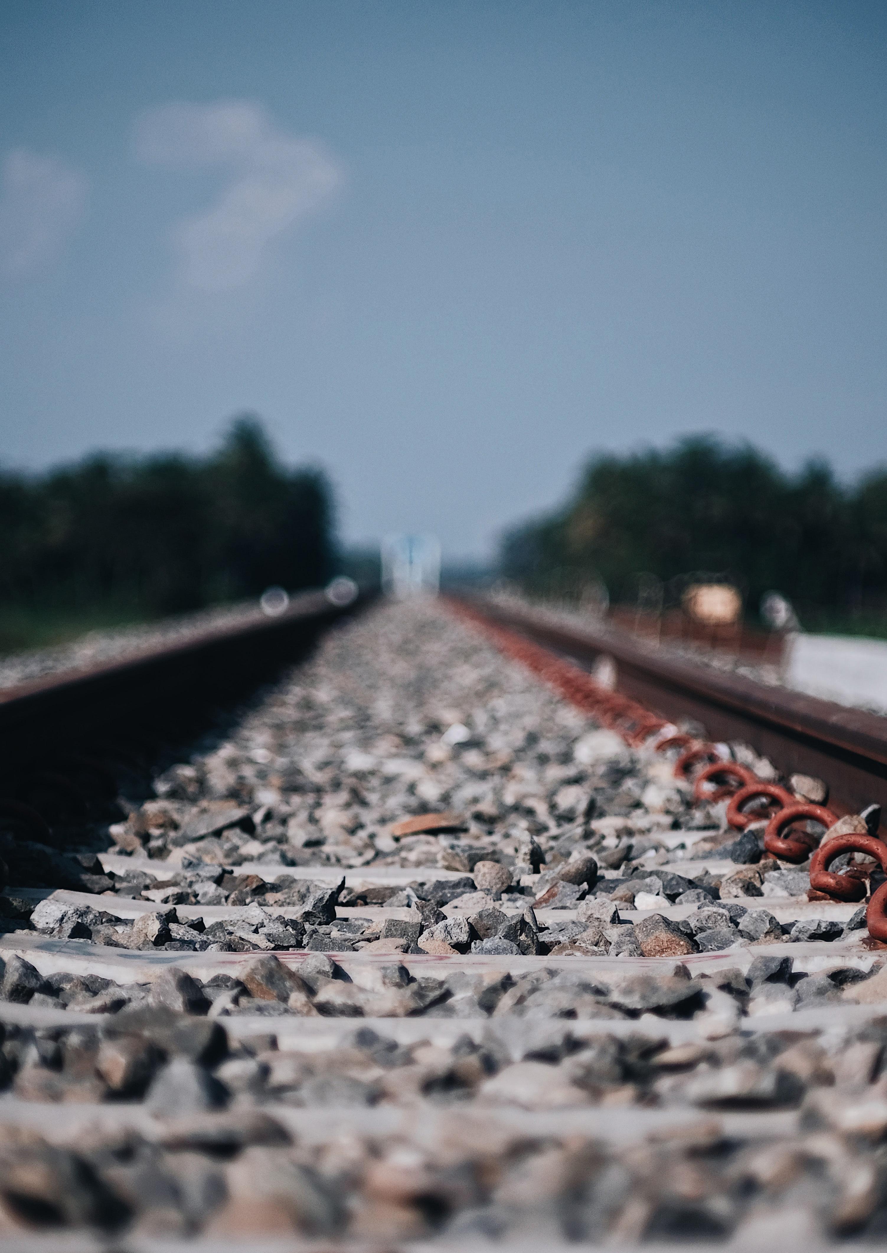
Finally, Joan Heery updated us on the work of the Climate Change and Decarbonisation group and their plans for future events including a seminar in 2022.

For details of Corporate Membership please contect
(kate.hatwell@thepwi.org)
Corporate Members are fully involved in the development of the PWI, ensuring that our products and services meet the needs of the rail industry for technical expertise.
Kate Hatwell PWI Operations Director
43
We have come a
LONG WAY
Following the success of the two electrification seminars hosted by the PWI, I suggested to David Packer (Former CEO, PWI) some three years ago that we should consider a plant seminar, which he fully supported, and following the agreement of the PWI Board, the planning began. Covid restrictions have meant that we have had a few false starts but hopefully it is all systems go now for 24 November at St James Park, Newcastle. Plant, both On Track Machines (OTM) and On Track Plant (OTP) are key in being able to deliver both construction and maintenance projects across all railway engineering disciplines.
It is clear we have come a long way from the early days of the pick and shovel to the big yellow machines we see today!
The following paragraphs give a whistle stop tour of the way innovation and development has led to a greater emphasis on mechanisation and less reliance on human effort and intervention. The plant seminar will showcase some of the current work to introduce further new technology and mechanisation, leading to greater productivity and improved workforce safety.
Jack is the Engineering Director of VolkerRail and is a qualified Mechanical and Electrical Rail Engineer with a background in electrification and plant. He Chairs the M&EE Networking Group which was established just prior to privatisation of British Railways to enable the Professional Heads of Mechanical and Electrical Engineering in successor companies to share knowledge and develop best practice.
Jack began his career at British Rail as an apprentice based at Doncaster in 1967 and has extensive experience in rail engineering and operations. In his journey from Apprenticeship to Fellowship, Jack has held senior and varied roles within BR and Balfour Beatty Rail as well as his current role in VolkerRail.

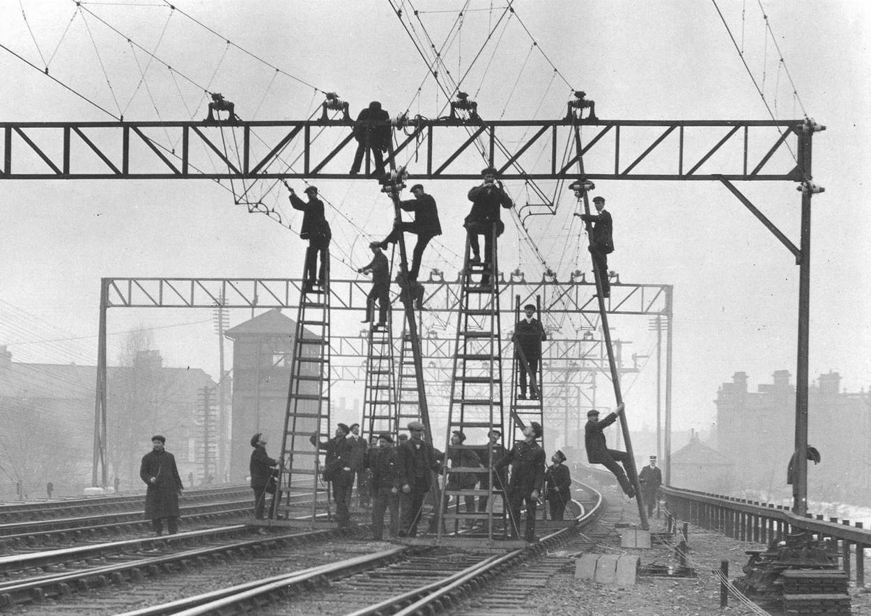 Jack Pendle
CEng
FIET
FIMechE
FPWI
Jack Pendle
CEng
FIET
FIMechE
FPWI
44
THE OLD AND THE NEW
Howard Elliot (1860–1928), President of Northern Pacific Railway, and President of New York, New Haven and Hartford Railroad.
The old methods of track work relied on the extensive use of manpower and was an extremely physical task using hand tools and brute force. Over the years there has been much development in railway machinery to undertake both track laying and relaying and in the day-to-day maintenance of the track, including ballast cleaners, tampers, high output relaying trains and more.


With modern ballast cleaner systems (BCS) there’s a significant reduction in the need for railway workers to be on the track while the work takes place, ensuring a higher degree of safety. Most operations are controlled from inside the cabs, limiting exposure to the dangers of diesel fumes, ballast dust and passing trains. Track renewal has benefited from mechanisation with the introduction of Track Renewals trains that replace existing rails and sleepers with high performing new ones.
The Track Renewals System (TRS) works in a similar way to the ballast cleaner in that it utilises a conveyor system. The front part runs on the old rails, while the rear runs on the new rail that the system has installed, so any lines adjacent to the one the TRS is working on can remain open to passing trains. Sleepers can’t be carried to and from the work site on the TRS in the normal orientation (across the track), so a crane fitted with a turntable rotates them through 90 degrees while moving them from the delivery wagon to the installation mechanisms, and at the same time loads the old sleepers on to the empty wagon.
The concept of Track Renewals trains is not new. Prior assembly of track panels was undertaken track side but had not been undertaken in more controlled conditions using a nearby yard until a system of transporting them was available. Hence the Morris Tracklayer was developed with the first machine being produced in 1923, which not only transported the panels and laid them, but which also removed the old track and took it away. The track layer was the brainchild of Arthur Bretland, the engineer of the Great Southern and Western of Ireland. Also, 50 years prior to this Phillipe Vitali, an engineer from Paris, took out patent 949 for a mechanical track laying machine that was laid out in the same way as the Morris tracklayer.
It is not only track renewal and maintenance that has benefitted from innovation and mechanisation, the development of both On Track Machines (OTMs) and On Track Plant (OTP) for undertaking overhead line works has improved both productivity and safety immensely.
The absence of PPE, working off ladders, straddling structures is something that is difficult to comprehend today. The use of converted rolling stock, removing the original arched roof and replacing it with a flat top provided a long flat platform which OLE linemen could work from. This methodology improved productivity but resulted in several serious incidents due to falls from the train causing life changing injuries to the staff concerned. Despite various proposals to make this safe including the infamous “bouncy castle” concept, the practice was deemed unsafe and alternative solutions needed to be developed.
Electrification of the West Coast Main Line in the early 1960’s saw the development of a range of railborne plant including 4.5 cu m concrete mixers and Poclain excavators mounted on rail wagons, with the design being undertaken on the hoof and without the issues of product and vehicle acceptance that we face today.


East Coast Main Line electrification included a budget for the design and development of new plant and equipment including new Atlas excavators, new 6.0 cu m Ransome and Rapier concrete mixers, a self-contained piling vehicle and a less successful manipulator and screw anchor machine. This was the Factory Train of the day for OLE construction.
To provide greater flexibility, the use of Road Rail Vehicles (RRVs) that could either drive directly to an access point or be hauled by road was called for. In the early days of development conversions were largely agricultural, with these being undertaken in cottage industry type environments. Today, standards and regulation mean conversions are properly designed, built, tested and certificated for use.
The Great Western electrification project introduced a new OLE design range developed by Furrer and Frey of Switzerland which was inherently heavier than equipment used on previous electrification schemes.
 Laying track Ryecroft late 19th Century
Network Rail’s High Output Ballast Cleaning System
Track Renewal Train
Morris Tracklayer Cambridge 1930
Mk1 OLE Installation Kenton 1964
Laying track Ryecroft late 19th Century
Network Rail’s High Output Ballast Cleaning System
Track Renewal Train
Morris Tracklayer Cambridge 1930
Mk1 OLE Installation Kenton 1964
‘You cannot have a good railroad without good track and good equipment, and good men to maintain and operate that track and equipment.’
45
There was also a need to introduce equipment with greater productivity to maximise utilisation of available access on the route. The project included budgetary provision for what was known in the early days as the ‘Factory Train’ - a (not entirely!) new concept that would revolutionize OLE construction. Made up of 23 vehicles forming five ‘consists’ the Factory Train has three specialised sections – each delivers a different stage of work:
Section 1 - Comprising two ‘consists’ each of five vehicles to build foundations for the main steel that carry the conductors. Five of them dig the foundations and fill them with concrete, while another five drive the steel tube piles into the ground. The piles measure between 610mm and 762mm in diameter.
Section 2 - Comprising three vehicles in the ‘consist’ that installs the main steelwork for the 15,000 OLE structures, as well as five in the ‘consist’ for installing ‘small parts steelwork’, and three to hang up the wires.

Section 3 - Comprising two platform vehicles for the final stages of wiring.

The High Output Plant System (HOPS) is preloaded with everything it needs to install the overhead wiring and the structures that hold the electrical equipment.
I hope I have shown, in the potted history above, that there has been huge development and innovation in railway plant and equipment over the years!
INTO THE FUTURE: AN OVERVIEW OF THE SEMINAR
The forthcoming seminar will cover many of the current developments and innovations in plant and equipment that will take us into a more productive, environmentally friendly, and safer future. As part of this, it is essential that knowledge and best practice is shared and the talk I will be making jointly with Mick James, “Best Practice Development for Plant and Machinery’ will explain the work of the M&EE Networking Group that exists to facilitate this.
The Group was established just prior to privatisation of British Railways to enable the Professional Heads of Mechanical and Electrical Engineering in successor companies to share knowledge and develop best practice.
The Group originally had 13 members, the professional heads of the seven Infrastructure Maintenance Companies (IMC) and six Track Renewals Companies (TRU). 26 years on from its formation, the group now has a permanent membership of 25+ which includes Professional Heads of Train Operations, Infrastructure Managers, RSSB, Rail Plant Association, plant training providers, acceptance bodies as well as converters and manufacturers.


As an example of its work, the Group has recently developed a memorandum of understanding with the Infrastructure Safety Liaison Group (ISLG) to better represent the plant community on both plant engineering and operations issues and workforce safety.
The seminar will include many other interesting talks, including (it is expected):
• Improving the safe use of plant and equipment
• The challenges of operating plant from Wick to Watford and HS1
• Advances in the automation of tamping
• Plant Innovation for Electrification
• I-Systems high performance protection Any Line Open (ALO) for On Track Machines
• Induction welding and more – experiences of breaking into the rail market
• Advanced cooling equipment – saves 15 minutes per weld
• Plant Innovation and who funds it
• Dynamic Track Stabiliser (DTS) the latest technology in the forefront of maintenance and renewal

• Plant robotic and automation
I’m certainly looking forward to a very interesting seminar and I sincerely hope to see you at St James Park, Newcastle, on 24 November.
See opposite page for full details
Plasser EPV 360 Atlas excavator
SCPV 14 Self Contained Piling Vehicle
RRV plant undertaking construction on Midland Main Line
Network Rail Factory Train
Mobile Elevating Work Platform (MEWP) unit developed recently for electrification work
46
PWI

Despite the recent falls in passenger traffic consequent on Covid-19, over the longer term the climate change and decarbonisation agendas remain set to drive growing volumes of freight and passenger traffic onto rail networks. As the demand for rail transport bounces back and as train services are added to the network to meet growing demand, access to carry out maintenance, renewal, and project work will remain at a premium.
The pressure to do more work in shorter possessions drives a requirement for more productive, mechanised, work delivery methods. Effective, safe, and highly productive plant is an essential component of this. Plant and the methods and strategies to deploy it that can together deliver high quality, durable infrastructure at lower unit costs is crucial to meeting industry challenges: along the way it must play its part in reducing rail sector carbon emissions and other environmental impacts, and in improving the performance and reputation of the railway.
This seminar will provide delegates and speakers with an opportunity to understand and debate the requirements for plant to meet these challenges, and the solutions that are being deployed and developed to deliver them.

TO SUPPORT RAIL INFRASTRUCTURE RENEWAL AND MAINTENANCE FOR THE 2020s AND BEYOND


TECHNICAL SEMINAR PLANT & MACHINERY
24 NOVEMBER 2021 ST JAMES’ PARK NEWCASTLE UPON TYNE BOOKING NOW OPEN: www.thepwi.org £85 MEMBER £150 NON-MEMBER SPONSORSHIP AND EXHIBITOR SPACE AVAILABLE Contact 01277 230 031 / secretary@thepwi.org
47
SPONSORED BY


¬ Technology: solar-powered LED ¬ Temperature range: -20°C (- 4°F) to 85°C (185°F) ¬ Output at full power: up to 240 hours without additional solar radiation ¬ Service life: more than 8 years ¬ Colours: yellow, red, white, green, blue (two per cover possible) ¬ LED configuration: one-sided and two-sided reflectors ¬ Charging time: approx. 3 hours on a sunny day STRAIL (UK) Ltd. - Richard Whatley Tannery Lane // Send / Woking // GU23 7EF // Great Britain // Phone +44 (14 83) 22 20 90 // Fax + 44 (14 83) 22 20 95 // richard@srsrailuk.co.uk FINDING YOUR WAY AT NIGHT AND IN FOG! pedeSOLAR The optional LED lighting for pedeSTRAIL level crossings. 48


SMART MONITORING & SAFETY SOLUTIONS REMOTE CONDITION MONITORING EXPERTS We help Maintenance Engineers to reduce costs and increase safety of team members by using smart IoT devices that will help you to provide better control of your assets. WHY PREDICTIVE MAINTENANCE? Predictive maintenance limits inefficiencies, improves safety, and saves you money 50% Less downtime IoT-based predictive maintenance can reduce asset downtime by 50% 100% Visibility Companies who implement sensors can monitor important assets 24/7 30% Reduced operating costs Predictive maintenance can lower op-ex costs by up to 30% Let us show you what our IoT Solutions can do for you and your business. CALL US NOW ON 0845 052 3860 or SEND US AN EMAIL TO: Info@yeltech.co.uk SLIDING FRICTION BUFFER STOPS SKELTON Rawie Friction Buffer Stops provide protection for track ends worldwide. They can be designed to suit all types of rolling stock, accommodating varied train weights and speeds. Manufactured by A.RAWIE GmbH & Co. KG. Tel: 0049 541 91 2070 bufferstops@rawie.de www.rawie.de Supplied in UK & Eire by H.J. Skelton & Co. Ltd. Tel: 0044 1635 866877 sales@hjskelton.com www.hjskelton.co.uk ARTICLES WANTED Whether you come from an academic or industry background, or a combination of both, if you are an expert in your field then we would love to hear from you. Do you have a particular topic you’d like to write about? Share your idea with us for a new technical article and our Technical Content Managers will get in touch to start the process. Email: journaleditor@thepwi.org 8 16 28 LICENCE GRANTED JOINS JOINT BOARD OF 56 34 49
GROW with us
HOW THE PWI CAN HELP YOU LEARN AND DEVELOP

Lifelong learning is all about recognising your drive to explore, learn, and grow both in traditional academic environments and beyond. Data from the Office for National Statistics (ONS) showed that in 2017, more than a quarter of employees in the UK said they had taken part in in-work training or education. This proportion will only increase as the coronavirus pandemic has fuelled a trend for learning new skills, which is far from fleeting, as a survey by The Open University found 24% of respondents had taken on additional learning opportunities to “boost their employability and protect the value of their skills”.
One of the PWI’s key objectives is to provide our members with opportunities to enhance and grow their knowledge of railway infrastructure engineering and related disciplines through accessible means. So, how can the PWI support you on your journey to acquire further knowledge and develop?
50
THOUGHT LEADERSHIP
How you express, share, and communicate your ideas is uniquely linked to and affects how you engage, understand, and consume them. You may be able to satisfy your curiosity on a topic by delving into resources independently, reading them at a desk in a quiet place and letting the information flow over you. This is the environment in which you might choose to enjoy this very Journal’s explorations of the hottest industry topics via insightful technical articles produced by experts and academics from across the world of rail infrastructure engineering. The PWI online shop is stocked with technical textbooks, including ‘Understanding Track Engineering’, ‘Track Terminology’, and ‘Switch and Crossing Maintenance.’ As a PWI member, you can also access all this information in the form of videos, articles, and presentations through our virtual Knowledge Hub.
Learning independently is great, but eventually there comes the need to engage with other likeminded people. Monthly Section meetings are a fantastic opportunity to meet and start discussions with other members of the PWI community and to hear speakers from across the industry present papers on various railway engineering topics. We are incredibly proud that Section meetings have continued virtually over the past year, providing members with the same opportunity to engage with one another, and will return to in-person attendance from September. Outside of Section meetings, you can also discuss factors impacting the rail industry in our LinkedIn groups.
TECHNICAL SEMINARS AND CONFERENCES
After you have been introduced to ideas and concepts by articles, videos or presentations where do you go from there? How do you expand your knowledge? One way is to challenge those ideas and push your understanding in new directions. Every year, the PWI hosts and takes part in a variety of technical seminars and conferences, which give our members the chance to do this by putting their questions to industry leaders in live Q&A sessions.
Our upcoming technical seminars include the second part of the joint institutional virtual seminar on: ‘High Performing and Flexible Railways for the Future’ on 3 November. Then in Newcastle on 24 November ‘Plant and Machinery to Support Rail Infrastructure Renewal and Maintenance for the 2020s and Beyond’, will explore how plant can play its part in reducing rail sector carbon emissions, and improving the performance and reputation of the railway. In early 2022, ‘Climate Emergency and Decarbonisation: The Railway’s Response’ will see speakers discuss the impact of changing weather patterns on the rail network, and projects which have provided sustainable long-term solutions.
PERSONAL AND PROFESSIONAL DEVELOPMENT
The learning you do to develop and maintain your knowledge can also help you to further succeed in your career. How? By focusing your learning on its relevance to your current role and your future ambitions.
Think about what you want to achieve in your career and seek out technical training courses that are specific to your goals and areas of interest. The PWI runs several highlevel technical training courses designed to develop your skills and knowledge in all aspects of track repairs, switches and crossings, renewals, projects and now electrification. All of which can be an advantage to railway engineers at any stage of their career. We also have opportunities for you to support the learning of others by delivering a training course or workshop.
The PWI offers a uniquely tailored professional development journey, and our website hosts a range of useful tools. This includes My CPD for recording what you have experienced and achieved in a structured way, and guidance on CV writing and interview techniques.


We are all lifelong learners, and every day you will continue to learn and develop in a variety of ways both personally and professionally whether it be by reading, undertaking research, participating in discussions, or supporting the wider community with your skills. Crucially, taking the time to reflect on your learning can lead to greater opportunities to explore what you have learnt and push yourself to grow and thrive. In the PWI community, you are free to take steps towards your own personal and professional goals, and we will support you all the way.
We hope this article highlights some of how you can learn and grow your knowledge within the PWI community and beyond. We would love to hear your thoughts.
marketing@thepwi.org 51
Luke Goulde
PWI MARKETING EXECUTIVE
DAN MOLL0Y REFLECTS ON HIS JOURNEY TO BECOMING CHARTERED
PROFESSIONAL REGISTRATION
Professional Registration is an important step in pursuing a career in engineering and it lends itself to a ready-made career path, progressing through the grades as your experience broadens and deepens.
Putting those letters after your name (EngTech, IEng or CEng) instantly tells employers, clients and wider society that your competence and understanding of engineering principles has been independently assessed, that you have the knowledge, skills and professional attitude they value, and that you are committed to developing and enhancing your competence. It sets you apart from your non-registered colleagues.
The right professional registration title for you is based on your academic and professional competence: here’s a general guide…
The academic route was never really for me. As a result, I dropped out of fulltime education at the age of 16 and went to work as a labourer on various construction sites.
A year later, I saw an advert and applied for a Track Maintenance Engineering Apprenticeship with Network Rail. This really appealed to me as it combined ‘on the job’ training with an opportunity of a career with a reputable company. I was successful in my application and started my railway apprenticeship in 2005, initially based at HMS Collingwood in Gosport as part of a residential course.
Over the 16 years since I started with Network Rail, I have been really fortunate to have held a number of positions which have challenged me to develop my engineering and managerial skills. Working from the ground up has provided me with a great insight into the challenges and demands at all levels in the organisation, and it also enabled me to build a strong network.
In order to develop my competence and recognition as an Engineer, I made the decision to start my professional registration journey in 2016. I was initially awarded Engineering Technician status and later achieved Chartered Engineer status in 2021 via the technical report route which has been my proudest career moment to date. This was a goal of mine that seemed out of reach, particularly for someone who never liked the classroom!
Engineering Technicians apply proven techniques and procedures to the solution of practical engineering problems.
They hold Level 3 engineering/ technology qualifications and 2-3 years industry experience, OR 3-5 years industry experience.
Incorporated Engineers maintain and manage applications of current and developing technology, and may undertake engineering design, development, manufacture, construction and operation.
They hold Level 6 (Bachelors) engineering/ technology qualifications and 3-5 years industry experience, OR 5-10 years industry experience.
Chartered Engineers develop solutions to complex engineering problems using new or existing technologies, and through innovation, creativity and technical analysis.
They hold Level 7 (Masters) engineering/ technology qualifications and 3-6 years industry experience, OR 10-15 years industry experience.
Whilst the technical report route was interesting and worthwhile, it was not without its challenges. It was particularly difficult for me to demonstrate my knowledge and learning to Masters level which required a significant amount of study and focus. The road to CEng was not a straight forward one, in fact I was not successful during my first technical interview which really impacted upon me and made me question whether it was worth continuing. After getting over the setback, I was determined to come back and be successful the next time around. So, after a significant amount of preparation I reapplied and was successful the second time around.
Attaining Chartered Engineer status has helped me immensely in my current role where I now lead multidisciplinary specialist engineering teams, and often have to make complex decisions and resolve issues outside of my core discipline.

My advice to other engineers who are thinking of pursuing professional registration is to identify a strong Supporter and Sponsor who can help to guide you through the process - this has been key for me, and I could not have achieved it without them. I was also extremely grateful for the support and guidance of friends, colleagues and the PWI throughout this journey, as there were times along the way where it would have been all too easy to have given up.
I hope my journey inspires and encourages others to progress with their professional registration, regardless of their background.
PROFESSIONAL REGISTRATION WITH THE PWI IS SUPPORTED BY NETWORK RAIL AND TRANSPORT FOR LONDON

 Molloy CEng FPWI Head of Technical Services Delivery Network Rail
Dan
Molloy CEng FPWI Head of Technical Services Delivery Network Rail
Dan
52
Right: Dan achieving Engineering Technician status in 2016
ENSURE
UK-SPEC IS CHANGING.
The Engineering Council has released a new version of UK-SPEC for all professional titles – CEng, IEng and EngTech – and the transition period closes this year. You can start to use the new version straight away, for determination this year or beyond – but any applications on the current version must be assessed this year, which means submission no later than 1 November 2021 to ensure it is processed in time.

The final IEng and CEng professional review interviews on the current version will take place in December 2021, as will EngTech reviews. All assessments in 2022 must be against the new version Competence and Commitment Criteria.
If you have not yet submitted your application, please download and use the new version forms and guidance. You’ll see that much of your thinking and preparations will transfer across.


The world of railway qualifications is changing, so why be behind the curve? It is time to stop “putting off” the start of your professional journey. This applies to track, structures, and electrification colleagues.
Liz Turner, our Professional Registration Manager has over 100 people on her list who have inquired but not followed it up, and she would be delighted to get a phone call (01277 230031 option 2) or email profeng@thepwi.orgstart the conversation!
The PWI now has over 250 registered engineers with over half being EngTech, the route available for all. We also have a great pass rate for IEng and CEng and routes to fit all with experience as well as academic qualifications.
The team has been working hard to simplify and streamline our applications whilst upholding our standards. We have new registrants and Reviewers who are keen to help register their colleagues and can provide help.
I have met lots of people on training courses and in companies who are surprised at what it means for them and did not know they could quickly and easily become EngTech MPWI.
Most companies pay for membership and applications. I had a meeting with Balfour Beatty staff in the summer and it was an obvious part of their employee retention strategy to encourage professional registration. I also know many others that want to keep their excellent staff because recruitment is often slow and expensive.
Brian Counter TECHNICAL DIRECTOR Permanent Way Institution technicaldirector@thepwi.org
The PWI is here for your journey and we would love to support you in your career aspirations.
Professional registration is open to any competent practising engineer or technician.
Different levels and pathways to registration are available, depending on your experience, training and qualifications.
FIND YOUR ROUTE TO REGISTRATION ON THE WEBSITE www.thepwi.org profeng@thepwi.org
CPD AUDIT 2021


Our Auditors are busy reviewing all the records received and identifying good practice.
We’ll share this in a future Journal.
YOU USE THE RIGHT FORMS! ARE YOU PREPARING AN APPLICATION FOR PROFESSIONAL REGISTRATION?
53
Head to the website to access all the new documents and information you need. We look forward to receiving your application on the new version, and new look forms! DO YOU SPONSOR COLLEAGUES? If you are or will act as a Sponsor for an applicant, please familiarise yourself with the new requirements.
over


d equipment specifically used for working on, or assisting in, the maintenance and r enewal of the railway infrastr uctur e in Gr eat Britain. It is a har dback, 360 page, full colour thr oughout, thr ead sewn publication with extensive colour illustrations. Included within it ar e compr ehensive details of:

s
r
■ On
■ Road/rail
■ Small
■ Owner
■ Manufacturer
On Track Plant 11th Edition can be obtained from Book Law Publications Copies cost £40.00 each - plus postage and packing. To obtain your copy, with secure online or dering, please visit: www.booklaw.co.uk Or ders can also be placed by telephone on: 0115 961 1066 Or by post from: Book Law Publications, 382 Carlton Hill, Carlton, Nottingham, NG4 1JA
of On- Track Pl ant - 11th Edition How to or der: 54
in the series of books first published
35 years ago. It is the definitive guide t o r a i l - m o u n t e d a n d
e l f - p
o p e l l e
track machines.
vehicles.
plant.
listings.
details.
Publishers
ACCELERATED COOLING:


THERMIT WELDS IN RAPID TIME


www.goldschmidt.com
high quality Thermit ® welds in a quicker time frame with Goldschmidt’s latest and most innovative weld cooling device. The Smartweld Ace is our answer to increased weld productivity via
system.
The Railvac and Ballast Feeder System industry concept delivers increased re-ballasting capacity. Always non-intrusive, with the track in situ and without disconnections!
55
Achieve
a controlled misting
Find out more at www.thermit-welding.com
www.railcare.co.uk
TECHNICAL TRAINING TO SUIT YOU
Autumn is here and we have now got off to a good start in a finally freedup environment to do more training! Firstly, congratulations to those who have recently got their Track Engineering Diploma following their hard work in the early part of the year. Secondly, the Scottish contingent who passed S&C Refurbishment in Glasgow with flying colours following a well organised practical survey visit at Terminus Junction.
You can still book into our next round of modules in track and electrification starting in November at Derby. Why not look at your future and make a difference next year? These courses and qualifications look great on your CV and show your employers and future employers that you have the passion to continuously update yourself and never stop learning.

We call it CPD – “continuous professional development” and it is essential for professionally qualified engineers.
Course programmes for 2022 are now fully planned with all courses running sequentially and track modules being offered face to face or virtual. S&C Refurbishment course provision is extended as the demand has gone up significantly. We now cover Light Rail and Metros where we have been working in conjunction with Transport for London.
If you have any questions about PWI training, please let me know. Also, please tell me if you’re interested in becoming a PWI trainer. With all our new courses, we need staff to do training in the classroom and online.
Good Luck with your training plans in 2022!
COURSES DELIVERED BY INDUSTRY EXPERTS

PWI training started over 100 years ago and has been providing high level technical training for engineers and professionals operating at all levels ever since. Our courses are designed to develop skills and knowledge in all aspects of track repairs, renewals and projects - and can help you on your journey to professional registration.
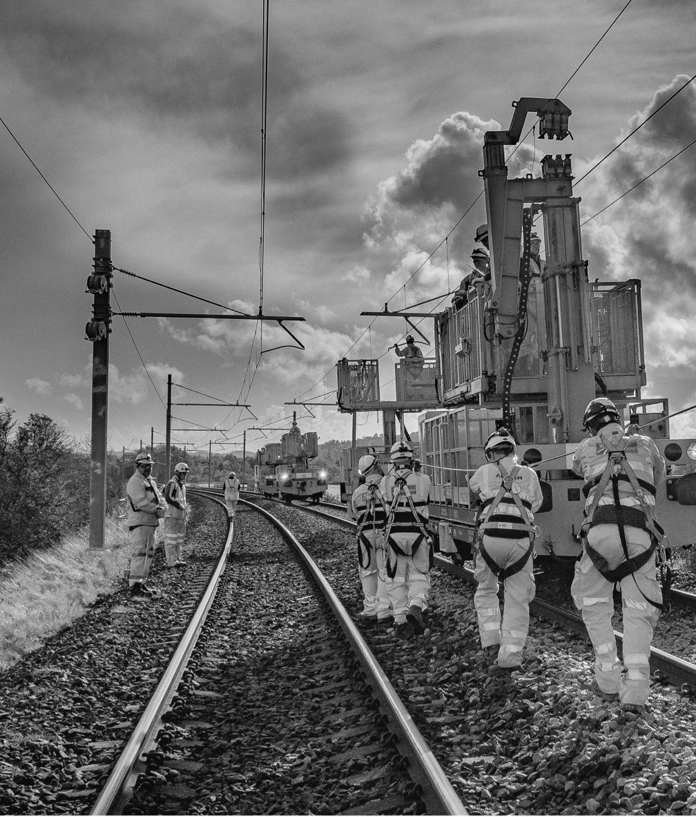
Join us in person or in our virtual classroom from your home or office as we deliver our industry revered, first class training directly to you. All PWI courses use the most up to date content and standards; both attendance options provide the same high quality materials, tutorials, group discussions, interactive working examples and access to tutors in a 1-to-1 environment to answer queries or recap areas of uncertainty. A printed course book, personal workbook and PWI textbooks will be made available in class, or posted to your home address ahead of your start date for virtual candidates.

Awards are made by the PWI upon successful completion of written or online assessments. These comprise Certificates and a Diploma, which has been professionally validated at university level.
In-person courses held at the Derby Conference Centre in Derby. These courses include all training materials and lunch. Accommodation at the venue includes evening meal, single room and breakfast.

All prices are exclusive of VAT.
FOR FURTHER INFORMATION AND BOOKING VISIT THE WEBSITE
WWW.THEPWI.ORG
secretary@thepwi.org 01277 230031 option 1 technicaldirector@thepwi.org
COVID-19 INFORMATION
We are monitoring our plans to deliver our training courses and are working very hard to ensure learning with us is not interrupted. We are committed to delivering first class technical training, developed and delivered by experienced rail infrastructure engineers. Please check the website for the most up to date information or contact us: secretary@thepwi.org 01277 230031 (option 1).
Image: Lawrence McEwan MPWI Principal Construction Manager - Network Rail
56
Brian Counter Technical Director Permanent Way Institution technicaldirector@thepwi.org
PWI ELECTRIFICATION ENGINEERING COURSE
The aim of the programme is to give delegates an understanding of the principles of the theory and practice of electrification engineering in the UK.
The trainers are all very experienced electrification engineers who have spent their careers designing, constructing, operating and maintaining systems in the UK and abroad.
The first development is the qualification in Overhead Line Electrification and is comprised of three consecutive modules involving 100 hours of taught study all mapped to HE Level 6. Upon successful completion of all three modular assessments, candidates will be awarded the PWI Diploma in Electrification Engineering (Overhead Line). Further development of supplementary modules will take place late next year to include 3rd/4th rail and side contact systems alongside power and distribution.
These courses are aimed at newly qualified and experienced engineers and will give delegates the knowledge and skills needed for professionals in electrification engineering.
Course dates run from Monday to Thursday

MODULE 1: SYSTEMS AND MAINTENANCE
1- 4 November 2021 / 16 – 19 May 2022 Derby
Gives a knowledge of OLE system types and the interfaces with the pantograph. Understanding the essential interfaces with other rail infrastructure including earthworks, structures and clearances. Knowledge of inspection, maintenance, servicing and repair processes. Gives an understanding of the concept of the UK rail system, operations, timetables, and legislation.
MODULE 2: DESIGN
24 – 27 Jan 2022 / 18 – 21 July 2022 Derby
Focuses upon electrification design for projects and enhancements. Understand design categories and processes. Develops skills in design of electrical, mechanical and civil engineering aspects including construction design and bonding design. Includes design case studies and exercises.
MODULE 3: ADVANCED ASSET ENGINEERING, CONSTRUCTION AND
25 - 28 April 2022 / 7 – 10 November 2022 Derby
The study becomes more strategic and delivery oriented with advanced asset management techniques and applications. Gain a deep understanding of UK OLE construction and renewal processes including commissioning, OLE system testing and handback to service. Understanding of ethical and sustainability aspects of OLE work and future proofing for climate change.
Course cost: £645 Accommodation cost: £245 See www.thepwi.org for full details
I learned aspects of OLE that I have never come across in my OLE career; this will benefit me in the future.
PWI S&C REFURBISHMENT
TRAINING COURSE
21 - 25 February 2022 / 13 - 17 June 2022 / 24 - 28 October 2022 / 20 - 24 February 2023
All Derby
Delegates on this course will gain comprehensive detailed knowledge of S&C and how to undertake refurbishment safely, efficiently and to the required engineering quality. The course will cover both the track assemblies and the trackbed under S&C.
Participants will undertake detailed analysis and inspection of layouts so that they can scope and specify work correctly to provide the necessary life extension of the layout. The course will then ensure that delegates understand the various maintenance interventions suitable for S&C and its components and can plan those required in the correct sequence. Modules include: S&C Components Design and Analysis / Site Survey and Measurement / Scoping and Planning.
Delegates will have to pass a formal assessment at the end of the course and will be awarded a PWI Certificate in S&C Refurbishment on successful completion.
Course cost: £895 Accommodation cost: £325 See www.thepwi.org for full details
I gained a huge amount of insight during the practical and now feel more confident around S&C. I would highly recommend this course especially if you want to gain knowledge of S&C to a high level from very knowledgeable people.
PWI TRACK ENGINEERING DIPLOMA
The aim of the programme is to give delegates an understanding of the principles, theory and practice of track engineering in the UK. It is comprised of three modules and involves 100 hours of taught study all mapped to HE Level 6. Upon successful completion of all three modular assessments, candidates will be awarded the PWI Diploma in Track Engineering.
Top-up qualification to IEng for HND / Foundation Degree Holders
This course is aimed both at newly qualified and experienced engineers, and will give delegates the knowledge and skills needed for professionals in track engineering.
Gives a basic understanding of track engineering and its theory and context. Develops a knowledge of track types and features, its interfaces with other rail infrastructure including earthworks, structures and clearances, and track maintenance including ballast, drainage, stressing, grinding and welding.
MODULE
3:
ADVANCED TRACK ASSET
ENGINEERING AND RENEWALS
- 9 Dec 2021 Virtual Classroom / 28 Feb - 3 Mar 2022 Derby / 9 - 12 May 2022 Virtual Classroom 26 - 29 September 2022 Derby / 5 - 8 December 2022 Virtual Classroom / 6 - 9 March 2023 Derby
The study becomes more strategic and delivery oriented with advanced asset management techniques and applications. Gain a deep understanding of UK track renewal planning, plain line, S&C, existing and future methods, rail renewal scenarios and optioneering, and learning from accidents. Understand advanced technical rail management issues, rail sustainability and strategic track asset management.
Module cost: £645 (Virtual or Derby) Accommodation cost: £245 See www.thepwi.org for full details
I found the three modules thoroughly enjoyable and valuable in developing my understanding of railway maintenance and its interdependencies. Thank you for putting together a brilliant course which was well presented. I am now interested in becoming an Incorporated Engineer.
12
MODULE 1: TRACK MAINTENANCE 8 - 11 November 2021 Derby / 7 - 10 February 2022 Virtual Classroom / 23 - 26 May 2022 Derby
- 15 September 2022 Virtual Classroom / 14 - 17 November 2022 Derby 6 - 9 February 2023 Virtual Classroom
MODULE 2: TRACK DESIGN 25 - 28 Oct 2021 Virtual Classroom / 17 - 20 Jan 2022 Derby / 4 - 7 April 2022 Virtual Classroom 18 - 21 July 2022 Derby / 31 Oct- 3 Nov 2022 Virtual Classroom / 16 - 19 January 2023 Derby Focuses upon track design for projects and enhancements. Through design case studies and exercises, develop skills in track design of plain line and switches and crossings, component knowledge and configurations, layouts, innovations and life extension, route evaluation and trackbed design.
6
Chris Fuller Network Rail
Jacob Fay Network Rail
57
Stephen Bamford Story Contracting
Minutes 2021 AGM
ITEM 3: The roll call of the Sections took place. All Sections were represented except for Ashford, Bengaluru, Croydon & Brighton, Edinburgh, Irish, Manchester & Liverpool, West Yorkshire and York.
2 JULY 2021, 16:00 – 17:05
MACDONALD BURLINGTON HOTEL, BIRMINGHAM & ONLINE
PRESENT: R Antliff, S Barber, P Benzie, J Bray, A Cooper, B Counter, P Ebbutt, J Edgley, A Franklin, S Featherstone, J Garlick, L Garner, S Green, K Hatwell, J Heery, R Hickman, A Jones, P Kirkland, N Millington, G Moullec, M NolanMcSweeney*, A Packham, W Powrie*, R Quigley, S Tarrant, E Turner, J Watson, S Whitmore*, A Wilson, J Scott*, R Antliff, M Acquati*, A Tappern*, P Dearman*, Steven Bell* (*virtual attendees, and thus observers to the meeting only).
APOLOGIES: J Cornell, I Griffiths, R Kimber, I Kitching, I Lane, K Newell, L Purcell, M Taylor, K Thurlow, R Wells, D Woods, M Woof, A Steele, R Brown, C Burnikell, P Edwards, C White
ITEM 1: President John Edgley formally opened the AGM, welcomed attendees in the room and those who have joined online, noting this as our first hybrid meeting. John explained that those attending virtually were requested to vote in advance via a proxy notice. Questions are welcomed via the chat function. Apologies for absence were received.
ITEM 2: John Edgley read the names of all PWI members who had passed since the last AGM, and a one-minute silence was observed in celebration of their lives. Attendees were also advised of the recent passing of Peter Lugg, London Section on 28 June 2021. The 18 names read were: William Thomas Armstrong, John Firth, Colin Dawson, Keith Ratcliffe, Nick Robertson, Geoffrey Bagley, Peter Muir, Albert Gray, Robert Michael Chorley, Roger Woodward, Howard Finch, Derek Norman Gaskell, Major John Poyntz, Charlie (Cyril) Smith, Bobby Telagamshetty, Donald Halliday, Richard Watson and Ciaran McEvoy.
ITEM 4: The Minutes of the 2020 AGM were received and proposed as an accurate record by Phil Kirkland, seconded by Andy Packham and the motion was carried unanimously.
ITEM 5: In his Presidential Report, John Edgley reflected on his year’s tenure noting it as an extraordinary year because of COVID and its legacy for the PWI and the industry. Footfall at stations dropped 62% and although it is starting to slowly increase, it is not known how long the recovery will take. This presents an opportunity for the industry to focus on innovations to give value for money. However, the industry’s safety record over the past year or two has not been where it needs to be and, with the drive for innovation, we also need to drive safety - which is Nick Millington’s focus in his Presidential year.
Sustainability and reducing our carbon footprint is the biggest opportunity for us - electrification and a lower emissions railway, particularly freight. We are custodians of a huge area of real estate too with responsibility to be professional stewards of that bio-diversity. We need to ensure infrastructure is reliable for today’s paradigm and tomorrow’s. Are we re-using our materials effectively? What more can we do? We are not as effective as we should be in reusing materials and we need to learn from the last generation who were effective at that so we become fit for the future. All this leads to innovation - Rail Technical Strategy and five functional priorities.
The theme I chose for my Presidential term was ‘competency’, coming back to the PWI’s original purpose, set out in 1884 to promote the advancement of technical training in the art of maintaining the ways and works of railways. This is still as relevant today and is our vision for the future. Whilst COVID hampered progress, work will continue to create a competency framework.
QUESTION: IRSE have a licensing scheme for competency. Has the PWI Board thought about adopting a similar route for technical competences?
RESPONSE: It has been debated and it is not the direction for the immediate, or indeed longer, term. We need to first build and then evolve the framework.
ITEM 6: In his Chief Executive Officer report Stephen Barber gave a summary of 2020, noting that it was an extraordinary year: a year dominated by COVID and our reaction to it. The PWI community came together to help change the business model - we moved into an effective virtual environment very quickly: the speed of adaptation impressive whilst retaining a focus to continue to deliver our long-term strategy. Stephen gave an overview of the year in numbers: individual members, corporate members, professionally registered members, training delegates, seminars and online Section meetings. Profit was down 70% year on year but was still positive.
Looking back - a lot of time and effort has been spent in building the Customer Relationship Management System and website but we have been let down by our contractor. The hope is that we are in a position to go-live in early autumn. The S&C Refurbishment course has been developed and is highly relevant to meet the needs within the industry. We have reshaped and rebranded the Journal and created a new Knowledge Hub. We became an employer - a sign of our growing maturity. We joined JBM in 2021. We maintained a high degree of member engagement, with our online offer and rapid deployment enabling us to stay where we needed to be for our individual and corporate members.
Looking ahead, our agenda includes: training, workforce safety, our industry position as infrastructure not just track and ballast, formalising competence (it is easy to underestimate the work required, but we are getting there), a diversity and inclusion pathway (culture change will take years, but we know where to aim), decarbonisation and climate change adaptation, and increasing member engagement.
58
QUESTION: Online Section meetings have been great, as got where couldn’t have otherwise been, but only notified of Sections personally aligned to - often finding out from LinkedIn of others. Can all Section meetings go out to the full membership distribution list, not just the Sections’?
RESPONSE: Our monthly newsletter details all Section meetings and we can look at sending individual meeting details to a wider distribution list. The new website / CRMS should enable embedded calendar links too which we can include in emails and newsletters.
ITEM 7: The Directors’ Report and Accounts to 31 December 2020 was presented by Andy Tappern by way of recorded presentation.
Andy noted that it had been a challenging year for all businesses, but the PWI performance was strong, finishing the year with a profit of £32. Turnover reduced by £50k, principally due to the loss of technical seminars and reduction in training courses. Subscriptions remained on target due to the superb support of our individual and corporate members. Training and its transition into the virtual classroom meant our losses were mitigated - a fabulous performance. Costs were controlled demonstrating our strong relationship with suppliers and venues. The main drivers within administrative expenses has been software moving into the online environment, along with the website development and transition to become an employer. On the balance sheet the main change is cash at bank, largely due to reduction in debtors. The increase in tangible assets is the investment in the new website.
We very much hope 2021 will see the return of face-to-face events and traditional PWI activities. This will be another very tight year; initial forecasts predict a very small operating loss of £5k, but we will be working hard to get back to break even.
QUESTIONS invited and none received.
The acceptance of the Directors’ Report and Accounts for year ending 31 December 2020 was proposed by Andy Franklin, seconded by Steve Featherstone and the motion was carried unanimously.
ITEM 8: John Edgley noted that Nick Millington was voted in as our next President at the last AGM, so no vote is required today. Nick, who was handed the gavel, was welcomed to the role and invited to provide an outline of his intended areas of focus.
Nick stated that this was a real privilege and recounted that his Dad had not approved of his desire to work in the railways but had signed him away to British Rail in 1990. Although he passed in 2007 not long after Nick achieved CEng, he would have been proud today. Nick thanked members for giving him this opportunity.
Nick advised that he is a hands on person and the railways have always fascinated him, providing a great career meeting great people. Whilst not a safety professional, he is in a safety leadership role, but everyone is a safety leader. People do not need H&S or IOSH to have a safety focus. Thinking ‘if only’ is never a nice place to be especially if someone has been hurt or worse. It should not take something brutal to make change - we can be agents to drive risk awareness and poor activity, whether decarbonisation, diversity and inclusion, or safety.
As an industry, we have become complacent with risk recently - 87 incidents in 18 months.
We need to constantly think about risk transfer - eg night workers. With the PWI, how can we innovate our way out of this? Innovation can reduce change resistance. We always look backwards but we need to look at what is coming toward us and plan how to get over it.
There are fundamental basics to getting safe outcomes - do we plan to prevent risk? Training and assurance - have you checked it, are you checking it, what are you learning, what are you feeding forward? We need to ensure the check and feedback cycle is embedded so we firmly look forward. What can we do to modernise the way we monitor, measure and inspect our railway? Drones could be our new normal.
If we all use our connections, we can make a difference. If one person per month makes a safety intervention and then tells 10 more, that’s the power of what we can do.
Nick also noted his connection with universities in Plymouth and Exeter and opportunity to follow up with them after Joint Board of Moderators (JBM) visits.
Diversity is imperative - loads of different people looking at the same problem through different lenses means a better outcome.
Electrification is essential to the low carbon agenda and we need to ensure we provide novel, easy to build OLE systems that coordinate with track.
Nick intends to visit all Sections during his term (though India may be difficult) as being out on the road (rails!) is a better way to engage with members and deliver messages.
QUESTIONS invited and none received.
Nick concluded by thanking John Edgley for his services and support to the PWI during his term of office.
ITEM 9: Steven Bell, Deputy President nominee had regretfully sent apologies at short notice so was unable to address members in person.
Steven Bell’s appointment as Deputy President was proposed by Joan Heery, seconded by Richard Quigley and the motion was carried unanimously.
ITEM 10: Before proceeding to introduce William Powrie who was proposed as a Non-Executive Director, Nick Millington noted that John Dutton had chosen not to stand for re-election.
Nick had the great honour of thanking John. On behalf of the Board, I’d like to thank John for his years of service. John has been a Fellow of the PWI for 20 years and, as a Non-Executive Director, has provided unswerving support to the Executive team. He was the principal driving force behind our successful application to the Engineering Council to obtain our licence and has been more than generous with his sound business advice. It is no exaggeration to say that the PWI would not be in the strong position it is today without John’s contribution and support. He will be greatly missed by all who serve on the Board. On behalf of the PWI membership, thank you!
William Powrie was unable to attend the meeting in person but provided a short biography which Nick read: William started his career as a British Rail civil engineering trainee, based at York. He left the railway to pursue a long and successful career in geotechnical engineering research, latterly focusing on the railway sector.
William rose to become Dean of the Faculty of Engineering and the Environment at Southampton University and is chair of the HS2 Independent Geotechnical Engineering Panel. He is a leading light of the UK Rail Research and Innovation Network (UKRRIN) and is extremely well placed to help the Institution strengthen its links with the UK’s academic community - to the benefit of all concerned!
William Powrie’s appointment as a nonexecutive director was proposed by Andy Franklin, seconded by John Edgley and the motion was carried unanimously.
ITEM 11: Stephen Barber’s re-election as an executive director was proposed by Steve Featherstone, seconded by Andy Jones and the motion was carried unanimously.
ITEM 12: Brian Counter’s re-election as an executive director was proposed by Joan Heery, seconded by Paul Ebbutt and the motion was carried unanimously.
ITEM 13: Phil Kirkland’s re-election as Vice President for Great Britain was proposed by Steve Featherstone, seconded by Roy Hickman and the motion was carried unanimously.
Nick Millington closed the AGM offering thanks to all for their active support of the PWI, for the help they will provide in his Presidential year, and for their attendance today whether in person or online, and urged all to stay safe.
59
NEW MEMBERS
We’re honoured to have you on board and are thoroughly looking forward to working with you. We’ll keep you updated on news and events via our monthly newsletter as we don’t want you to miss a thing. We have a thriving social media network and we’d love to see you get involved! We’re here to help, so if you have any questions, then shout out!
Ashford: Stanley Chandler. Bengaluru: Aneesh Dhiman. Birmingham: Geoffrey Bayliss, Hannah Carey, Dan Page. Cheshire & North Wales: Joshua Pope-Lewis. Croydon & Brighton: Grant Gigg, Enesi Yisa, Solomon Williams. Edinburgh: Daniel McDonald. Exeter: Catherine Lamb, Mark Collison. Glasgow: David Girdler, Fraser Wilson, Samantha Anderson. International: Ivan Nyakana, Derek Piwonka, Alex Paul T, David Lazarus-Priestley, Dr Robrecht Schmitz, Ravi Teja Koralla. London: Jack Parsons, Joshua Morgan, Noel Dolphin, Matthew Paterson, Geoffrey Kenworthy, Jason Rogers, Michal Popko, Augustine Onwuzuruoha, Augustine Ogugua-Asolo, Mark Taiwo, Miroslav Balaz, Sadique Ahmed, Mohammed Ameen, Abdinasir Darbiye, Naharie Green, Lucas Dambitis, John Walker, Harry Anderson, Eamonn Maloney, John Fashade, Michael Rodwell, Frank Bennett, James King, Bradley Vollans-Giles, Glenn Wiles, Dovile Azukiene, Abbie Ring, Lee Hewitt, Yash Suresh, Lateef Bawahalla, Gajendra Verma, Robert Forsyth. Manchester & Liverpool: Mark Sanders, Brian Reynolds, Greg Salisbury, Dylan Sandhu. Milton Keynes: Steve OBrien. North East: Connor Allen, Mark Beighton, Anthony Dixon, Josh Heywood. Nottingham & Derby: Mark Horridge, Michael Percival, Roman Tomchenko, David Peet, John Hayes, David Varo, Benjamin Spitzmuller, Lewis Thomas. South & West Wales: Jack Hill, Rhys Mason, Joshua Corney, Dr Akash Gupta, Graham Pirson. West of England: Jordan Darrah. West Yorkshire: Andrew Backhouse. York: Neil Ashcroft, Paul Hooper, David Constable, James Backhurst, Shaun Wilson, Ozgun Sunar, Daniel Barr, Paul Bartliff, Harriet Smith.
FELLOWSHIPS

Noel Dolphin – London

Paul Hooper – York
Robert Sherrin – Wessex
Andrew Collinson – York
Peter Hazard – London
Glenn Wiles – London
PROFESSIONAL TITLE
A huge well done to our members who have gained a professional title since the last Journal. This is an amazing achievement.
Lee Herron - Engineering Technician
Graeme Bleach - Engineering Technician
Neferti Siddons - Engineering Technician
Karl Kiernan - Engineering Technician
Luke Boggis - Engineering Technician
Ryan Lord - Engineering Technician
Mark Willson - Engineering Technician
Aykut Ozparlek - Engineering Technician
Lewis Brown - Engineering Technician
Olanrewaju Salawu-Taiwo - Engineering Technician
Rob Brotherton - Engineering Technician
Aaron Dann - Engineering Technician
Shaun Streeter - Engineering Technician
Rasib Riffat - Incorporated Engineer
Richard Marsh - Incorporated Engineer (Additional)
David Parks - Chartered Engineer
Mark Paget - Chartered Engineer
Dr Matthew Brough - Chartered Engineer
Bleddyn-James Davies - Chartered Engineer

Arnaud Lizet - Chartered Engineer
PWI TRACK ENGINEERING DIPLOMA


Abdirahman Ahmed, Bilal Jahangir, Clifford Ogan, Daniel Dowding, Dona Petrova, Eun Seo Oh, Hamza Acharoui, James Charnock, James Walters, Jonathan MacMillan, Marc Berman, Matangi Tarmier, Menaz Ahamed, Muhammad Qasim, Samantha TomlinsonWrenn, Saqib Ahmed, Sua Cho, Tofazzal Rashid, Yashvir Bhatti, Arjun Johal, Benjamin Wood, Cameron Malone, Dilraj Gakhal, Douglas Veitch, Elliott Gordon, Fahim Khan, Gareth Holt, George Myers, Gregory Whiteley, Huseyin Kocadag, James Eyland, Joseph Dunleavy, Leon Ballin, Lewis Matheson, Liban Abdi, Luke Etheridge , Matthew Lock, Nathan Brunnen, Sophiya Thavabalalingam, Mark Higgins, Joe Simmons, Benjamin Tarten, Richard Pearson, Mark Kilshaw, Antonio Carr, Michael England, Gavin McDonald, Callum Sanderson, Lee Humphreys, Scott Sloan.
PWI S&C REFURBISHMENT COURSE
Harriet Smith, Jacob Hudson-Muscroft,, Lin Deuchar, Alex Hill, Rob Dunn, Matthew Leggett, Elliott Johnson, Ross Briddon, Jamie Ferguson, Mark Eves, Alistair Hume, Peter Whalley, Kevin Paterson, Adam Rapley, Kate James, Clifford Pitt, Robert Benson, Shane Harris, Blair Cockburn, Ryan Lynch, Stephen Dobbin, Michael Lowrie, Iain Craig, Liban Abdi, Kevin Kinney, Josh Houston, Scott Wintrip, Jack Dawson, David Downs, Noel Milligan, Owen Craik, Fraser Barclay, Stuart Merry, Ewan Pollock, Anthony Reilly.

www.thepwi.org/shop/ FYI: READING COUNTS TOWARDS YOUR CPD! VOL 139 PART JULY 2021 INFRASTRUCTURE AND THE INSTITUTION 8 16 22 28 LICENCE GRANTED JOINS JOINT BOARD OF 4 56 46 34 60
TECH TALK
Nick Millington President president@thepwi.org

Peter Dearman Deputy President dearman745@btinternet.com


Steven Bell
Deputy President steven.bell2@babcockinternational.com

John Edgley
Past President john.edgley@networkrail.co.uk


Andy Cooper
Non-Executive Director mrandrewjcooper@gmail.com
Prof. William Powrie Non-Executive Director w.powrie@soton.ac.uk
Non-Executive Director michelleusrm@aol.com

Andy Tappern
Non-Executive Director andy.tappern@networkrail.co.uk


Brian Counter
Technical Director technicaldirector@thepwi.org
Andy Steele
Technical Content Manager andy.steele@thepwi.org

Liz Turner

Registration Manager profeng@thepwi.org
Paul Ebbutt
Professional Registration Development Officer (South) 07887 628298 developmentofficersouth@thepwi.org
Brian Parkinson
Professional Registration Development Officer (North) 07876 578905
developmentofficernorth@thepwi.org
Chief Executive Officer stephen.barber@thepwi.org
Kate Hatwell Operations Director kate.hatwell@thepwi.org

Joan Heery

Membership Director joan.heery@theowi.org
Sara Green
Membership Secretary secretary@thepwi.org
Michelle Lumiére
Head of Marketing michelle.lumiere@thepwi.org
Kerrie Illsley
Creative Manager kerrie.illsley@thepwi.org journaleditor@thepwi.org


Luke Goude Marketing Executive marketing@thepwi.org
Tech Talk is a private forum where members can discuss, debate and share views on all things related to rail technology. Members can ask questions and make comments about the technical articles that are published in the PWI Journal, as well as react to our technical seminars, Boards and relevant news.
We encourage healthy debate and differences of opinion, but ask that contributions remain friendly and respectful at all times. Simply request to join!
www.linkedin.com/groups/8862498/

YOUNG ENGINEERS SECTION

AMBASSADORS
PROFESSIONAL REGISTRATION
This virtual Section has been formed on LinkedIn and provides a central location for all the younger members of the rail community to engage whilst remaining a member of your regional home Section.

The Young Engineers Section is a place to exchange thoughts, ideas, views and challenges you may be experiencing in your role as a young person working in the rail industry. It’s a place to gain and offer support, to meet likeminded individuals, and to participate in social activities as the group becomes more defined. Simply request to join!
www.linkedin.com/groups/8865220/
This forum connects PWI Ambassadors to discuss ideas, suggest collaborations and to receive updates and announcements from the central team.
PWI Ambassadors are free to post comments, ideas and suggestions to fellow Ambassadors or for the attention of the PWI central team. We continue to seek new Ambassadors and Young Ambassadors, and aim to appoint at least one Ambassador for every Corporate Member. If you wish to volunteer or nominate a colleague, please contact: marketing@thepwi.org
www.linkedin.com/groups/8913254/
This group is for all those embarking on their Professional Registration journey, as well as those who have already completed the process. Connect with each other, raise questions, discuss challenges and gain support from your peers.

We encourage members to treat this as an alumni network for PWI Professional Registration, allowing you to make friends and stay engaged with others who have undertaken the same journey, and to offer your experiences and mentorship to others when possible. Simply request to join!
www.linkedin.com/groups/8976547/
Michelle Nolan-McSweeney
Stephen Barber
61
PWI TECHNICAL SEMINAR CLIMATE EMERGENCY & DECARBONISATION THE RAILWAY’S RESPONSE

Climate change and the consequent requirement to both adapt and decarbonise global society is the largest and most important issue facing humanity. Engineering and engineers have a critical role to play: in defining the policies and actions necessary to avert physical and societal collapse; and in working with government, other key disciplines and industry to win the arguments so that those actions are taken with the urgency necessary.
In recent months the Permanent Way Institution has become more focused in this arena as it is of huge relevance to our community. The Manchester and Liverpool Section are therefore delighted to host a technical seminar on the subject of “Climate Emergency and Decarbonisation”. Delegates will hear from a range of speakers, from those dealing with understanding weather patterns and the implications for the rail network, through to projects which have provided sustainable long term solutions.
The industry is very much at a stage of gathering and sharing knowledge and experience on this important subject and this is a technical seminar that cannot be missed.
This event contributes to CPD.
3 MARCH 2022 MANCHESTER CONFERENCE CENTRE BOOKING NOW OPEN: www.thepwi.org £85 MEMBER £150 NON-MEMBER £10 STUDENTS SPONSORSHIP AND EXHIBITOR SPACE AVAILABLE Contact 01277 230 031 / secretary@thepwi.org 62


PERMANENT WAY INSTITUTION MEMBERS SAVE £5 SPECIAL SUBSCRIPTION OFFER - SPECIAL SUBSCRIPTION OFFER Established for 50 years, Modern Railways has earned its reputation in the industry as a highly respected monthly railway journal. Providing in-depth coverage of all aspects of the industry, from traction and rolling stock to signalling and infrastructure management, Modern Railways carries the latest news alongside detailed analysis, making it essential reading for industry professionals and railway enthusiasts alike. TO CLAIM YOUR DISCOUNTED SUBSCRIPTION Simply enter code PWIMR in the coupon code box at the checkout page when ordering online at: shop.keypublishing.com/mrsubs Alternatively, call: 01780 480404 quoting code PWIMR to the operator Lines open 9.00-5.30pm Monday-Friday. All details correct at time of going to press. Offer ends 31 December 2021 *Offer not valid on Direct Debit subscriptions. 229/21 ON A SUBSCRIPTION TO 63
FItted with a more powerful low emission EUR5 compliant engine.
Faster, lighter weight and lower vibration exposure.


Tighten and loosen all types of screwed fasteners and drill holes in Wooden Sleepers.
Can be mounted onto existing and new Master Tool Carriers.

Replacing Insulated Joint End Posts.
Adjusting gap on jointed track, Switches and Crossings and to correct for creep movement.


Replacing broken and worn fishplates using Master 35® Impact Wrench.
Adjusting breather switches utilising nearest fishplate joint.
Will remove the toughest of frozen/rusty Clips.
Use on outside track and inside the MMT in conjunction with Floating Trolley
Fastclip Remover
Will install and remove Clips quickly using our quick change Jaws
Battery, Diesel & Petrol Trackpack
40 Couper Street, Glasgow, G4 0DL T: 0141 552 5591 F: 0141 552 5064 E: enquiries@maximpower.co.uk W: www.maximpower.co.uk NEW Master 35® Impact Wrench & Tool Carrier NEW Lase Align Melvelle E Clip Remover Rail Gap Adjuster
New Improved version. Ideal for the following : Switch tip alignment Track Slewing Switch Positioning Crossing Nose Alignment Rail Dip Measurement T R A C K M A I N T E N A N C E E Q U I P M E N T For more information, contact us: e: tracksupplies@balfourbeatty.com t: 0114 241 5000 Balfour Beatty offers a wide range of components for rail construction and maintenance projects. Our products include: – Rail sections – Sleepers and timbers – Track smalls – Industrial switches and crossings To find out how we help our customers find the right part for their job, visit: www.balfourbeatty.com/tracksupplies Expert supplies for every job 64
200+
PWI Section meetings are great places to learn about rail projects and new technical developments, and network with other rail professionals.
The Sections page on the website hosts useful meeting information such as locations, meeting details, and how to attend.
Simply continue to send your reports including presentation details and any photos to secretary@thepwi.org
CENTRAL ENGLAND
VICE PRESIDENT Richard Quigley richard.quigley@ networkrail.co.uk
BIRMINGHAM SECRETARY Richard Quigley 07715 132267 richard.quigley@networkrail. co.uk Venue: 2nd Floor, Network Rail, Baskerville House, B1 2ND
MILTON KEYNES SECRETARY Kevin Thurlow 07802 890299 kevin.thurlow@ networkrail.co.uk Venue: Auditorium, The Quadrant, MK9 1EN
NOTTINGHAM & DERBY SECRETARY John Garlick 07532 071727 jgees01@ btinternet.com Venue: Aston Court Hotel, DE1 2SL / Jury’s Inn Hotel, NG2 3BJ
IRELAND
VICE PRESIDENT Cathal Mangan cathal.mangan@ irishrail.ie
IRELAND SECRETARY Joe Walsh 00 353 872075688 pwiirishsection@gmail.com Venue: Wynn’s Hotel, Dublin 1, Ireland, D01 C9F8
NORTH EAST ENGLAND
VICE PRESIDENT Phil Kirkland philkirkland@ btinternet.com
NORTH EAST SECRETARY Phil Kirkland 07899 733276 philkirkland@btinternet.com Venue: Newcastle College Rail Academy, NE10 0JP
WEST YORKSHIRE SECRETARY Martin Wooff 07487 652622 pwi@railrace.co.uk
YORK SECRETARY Vacancy 07951 918236 york@ thepwi.org Venue: Network Rail Meeting Rooms 0.1, George Stephenson House, YO1 6JT
NORTH WEST ENGLAND & NORTH WALES
VICE PRESIDENT Roy Hickman royhickman@live. co.uk
CHESHIRE & NORTH WALES SECRETARY Lynne Garner cheshire@thepwi.org 07494 753652 Venue: Crewe Arms Hotel, CW2 6DN
LANCASTER, BARROW & CARLISLE SECRETARY Philip Benzie p.benzie@ yahoo.co.uk 01704 896924
Venue: Station Hotel, PR1 8BN / Royal Station Hotel, LA5 9BT / Network Rail, CA28 6AX / Network Rail, CA1 2NP
MANCHESTER & LIVERPOOL SECRETARY Richard Wells richard.wells@tonygee.com 07817 302652 Venue: Manchester Metropolitan University, Room E0.05, M1 5GD
SCOTLAND
VICE PRESIDENT Tom Wilson tom.wilson@wsp.com
EDINBURGH SECRETARY Mark Taylor marktaylor5@ networkrail.co.uk 07710 959630 Venue: The Scots Guards Club, EH12 5DR
GLASGOW SECRETARY Angus MacGregor glasgow@ thepwi.org 07775 544509 Venue: WSP Offices, 7th Floor, G1 3BX
SOUTH CENTRAL ENGLAND
VICE PRESIDENT Paul Ebbutt paulebbutt1@gmail.com
LONDON SECRETARY Sean Tarrant seantarrant@tfl.gov. uk 07764429211 Venue: Transport for London, SE1 8NJ / Transport for London, E20 1JN
THAMES VALLEY SECRETARY Richard Antliff richard.antliff@gmail. com 07804 329497 Venue: Network Rail Offices, Davidson House Offices, RG1 3EU
WESSEX SECRETARY Kenneth Newell kenneth. newell@btinternet. com 07771 668044 Venue: The Rose and Crown, SE1 8DP / The Eastleigh Railway Institute, SO50 9FE / Network Rail Offices, Waterloo Station, SE1 8SW
SOUTH EAST ENGLAND
VICE PRESIDENT Jonathan Bray Jonathan.bray@ keolisameydlr.co.uk 07976 199011

ASHFORD SECRETARY Colin Burnikell colin.burnikell@hilti. com 07801 913562 Venue: Online until further notice
CROYDON & BRIGHTON SECRETARY Colin White c.white@ chaucerrail.co.uk 07845 316042 Venue: Mott MacDonald House, CR0 2EE
LONDON SECRETARY Sean Tarrant seantarrant@tfl.gov. uk 07764429211 Venue: Transport for London, SE1 8NJ / Transport for London, E20 1JN
SOUTH WEST ENGLAND & SOUTH WALES
VICE PRESIDENT Andy Franklin andy. franklin@networkrail.co.uk 07901512293
WEST OF ENGLAND
SECRETARY Constantin Ciobanu western@thepwi.org 07549 319335 Venue: Engine Room, Atkins, SN1 1DW
EXETER SECRETARY Mark Woollacott Mark.woollacott@ networkrail.co.uk 07920 509011 Venue: Mercure Exeter Rougemont Hotel, Queen Street, EX4 3SP
SOUTH & WEST WALES
SECRETARY Andrew Wilson southandwestwales@thepwi. org 07974 809639 Venue: Network Rail Offices, CF10 5ZA
INDIA
VICE PRESIDENT Tom Wilson tom.wilson@wsp.com
BENGALURU SECRETARY Srinagesh Rao sringagesh. rao@arcadis.com Venue: Arcadis Sez Office Bengaluru, Karnataka 560045, India
INTERNATIONAL CONTACTS
MALAYSIA Mr K Sukumaran sukumaran@ktmb.com.my NEW SOUTH WALES Peter Boonstra secretary@ pwinsw.org.au QUEENSLAND Robin Stevens robin. stevens@qr.com.au SOUTH AUSTRALIA Mark Pronk mark. pronk@sa.gov.au
SECTION MEETINGS A YEAR! 65
Our wonderful new website hosts full obituaries of all our cherished members who have sadly passed away this year. Unfortunately, the website is delayed due to Covid related supplier issues, so you will not yet have seen the full obituary’s for Albert, Mike, Bobby, John, Donald, Charlie or Peter, but I can assure you they make for meaningful and poignant reading. We are hoping the new website will be live for you to access them very soon.


It’s always a sad moment when I receive an obituary email, but when I read about our members and their incredible careers, my heart lightens to know that these people were cherished and valued members of our community. Apart from my dear friend Alison Stansfield, I have never met, in person, any of the members whom obituaries I have included in the 2021 Journals, yet I feel I know them all in some way. Here are the memories and details that stood out to me.
Kerrie Illsley - Creative Manager kerrie.illsley@thepwi.org / journaleditor@thepwi.org
WITH VERY FOND

MEMORIES

Full obituary’s for Albert, Mike, Bobby, John, Donald and Peter are ready for you to read on the new PWI website which we hope will be live very soon.


Peter was a welding expert and a true ‘Railwayman’. As a very young boy, was taken by his Father to visit a ‘Mr. Williams’ who was a retired former GWR employee who had once actually met Brunel, and the memory of this meeting was treasured by Peter throughout his life. Retiring from the ‘big railway’ in 1989, Peter redirected his energies into a variety of activities, helping others as a volunteer ‘taxi’ driver taking people to medical appointments. “Peter was very much a Gentleman, patient, kind, generous in spirit and willing to listen to people. He also had a great sense of humour and we shared many laughs over some of the ironies in the railway and in life. Peter also had a great love of music, and had a strong Christian faith, supporting his parish as a Church Warden for many years.”
Bobby lost his fight with Covid-19 at 42 yrs old. His obituary was shorter than others but it seems that he left a great legacy of technical excellence. Bobby achieved double fellowship with FCIHT and FPWI and was passionate about training and mentoring. The collection of photographs (on the new website obituary) left my heart heavy for some time; they show Bobby to be a family man full of smiles. “Bobby left a great legacy of technical excellence and will be always remembered as one of the leaders who had lots of potential.”
Charlie served in the Royal Navy and survived after being lined up to be shot in the jungle after mistaken identity, and after the war he worked in the building trade repairing bomb damaged houses. He was also a prankster, his obituary talks of an hilarious story about decorating a tree at a station with bananas and apples - passengers could not believe their eyes! “His wealth of knowledge, his patience, and his desire to help people left a lasting impression on those that knew him.”
Albert honed his culinary skills in the Catering Core during his National Service and was well known as a bit of a “cordon bleu”, cooking to the highest standards of haute cuisine. He had a vibrant sense of humour and adopted the nickname ‘Shirley Temple’ amongst the railway fraternity because of his renowned hair style! “Thank you Albie from all your colleagues for some great times and great memories, whether it was deep inside an industrial mining, steel or chemical complex, or out on a rural branch line somewhere. May you now forever rest in peace.”
Mike met his wife when she was a nurse and tended to him in hospital. Mike was always very supportive of young staff and encouraged them to achieve their goals. He was a globetrotter - China, Kazakhstan, Ethiopia and Pakistan where his inspection train was blown up by terrorists. Thankfully Mike survived! After retirement, he tried to visit a new country every year. “Mike’s large circle of senior railway friends ensured that the section always had a full and interesting programme of meetings. His enthusiasm for all things railway related will live on by all that knew him.”
John’s obituary spoke of him being one of life’s true Gentlemen and a joy to be with. He travelled extensively and had many talents including being one of the pioneer hovercraft pilots in the Royal Corps of Transport (RCT). As accident officer, John was on 24-hour standby and the first point of contact for some of the UK’s most serious railway incidents including Southall, Ladbroke Grove and Hatfield. “His enthusiasm for anything on the railways was unparalleled and he would often be seen with a notebook in hand, while looking from a train window.”

Donald recalled holding the blueprints for the aborted Dawlish Avoiding Line whilst in the Paddington offices in 1944. He contributed to the Continuous Welded Rail Policy, proving that by concentrating on re-laying the most heavily used lines completely, the savings in maintenance more than offset the initial outlay. He was involved in the Planning and execution of a new bridge at Chester Road, Birmingham where the old bridge was removed and the new bridge put in place in one impressive 30 hour procession of the line! “Donald worked on the British Rail West Coast Mainline modernisation, including the 1960s rebuild of Birmingham New Street station. Starting as an apprentice draughtsman in the 1940s, his career shows the value of lifelong learning.”

 Peter Lugg FPWI
London Section
Bobby Telagamshetty
FPWI India Section
Charlie Smith MPWI
London Section
Peter Lugg FPWI
London Section
Bobby Telagamshetty
FPWI India Section
Charlie Smith MPWI
London Section
East Section
Albert (Albie) Gray MPWI
North
Robert (Mike) Michael Chorley MPWI Lancaster, Barrow & Carlisle Section
Major John Poyntz
FPWI London Section
Donald (Don) Geoffrey Halliday FPWI West of England Section
66
Our thoughts go out to the families, friends and colleagues of all our members who have died.
PWI

ELECTRIFICATION DELIVERING THE BUSINESS CASE


The Scottish Government has recognised the benefits of a rolling programme of electrification and Network Rail Scotland is developing those plans. Electrifying an existing railway requires the electrification system to be integrated into the broader railway system: the configuration of the traction system and its constituent parts has implications for the operation, maintenance, and performance of the railway.
The challenge facing engineers of all disciplines is to simplify the systems integration task so that it supports a rolling programme of electrification rather than impedes it. This seminar will help engineers across the railway disciplines understand the implications of converting a route to electric traction, and explore ways in which system specification, design, and implementation can support a rolling plan.

TECHNICAL SEMINAR
21 APRIL 2022 GLASGOW ROYAL CONCERT HALL BOOKING NOW OPEN: www.thepwi.org £70 MEMBER £120 NON-MEMBER £10 STUDENTS SPONSORSHIP AND EXHIBITOR SPACE AVAILABLE Contact 01277 230 031 / secretary@thepwi.org
67
SPONSORED BY


ELECTRIFICATION: DELIVERING THE BUSINESS CASE 21 APRIL 2022 09:00 - 16:30 GLASGOW ROYAL CONCERT HALL £70 MEMBER £120 NON-MEMBER £10 STUDENT PLANT AND MACHINERY: SUPPORT TO RAIL INFRASTRUCTURE RENEWAL AND MAINTENANCE FOR THE 2020s AND BEYOND 24 NOVEMBER 2021 09:00-16:30 ST JAMES’ PARK NEWCASTLE UPON TYNE £85 MEMBER £150 NON-MEMBER SPONSORSHIP AND EXHIBITOR SPACE AVAILABLE FOR ALL SEMINARS Please contact 01277 230 031 (option 1) / secretary@thepwi.org PWI SEMINARS PROVIDE A UNIQUE PLATFORM FOR INCREDIBLE NETWORKING AND KNOWLEDGE EXCHANGE. CLIMATE EMERGENCY & DECARBONISATION: THE RAILWAY’S RESPONSE 3 MARCH 2022 09:00 - 16:30 MANCHESTER CONFERENCE CENTRE £85 MEMBER £150 NON-MEMBER £10 STUDENT 68

