16 minute read
Voltage controlled clearances: Reducing 25kV electrical clearances

by The PWI

Voltage controlled clearances:
Reducing 25kV electrical clearances
Advertisement
AUTHOR: Dr Paul Naylor BEng(Hons) PhD CEng MIET
Paul has over 18 years’ experience of railway electrification systems and five years’ experience of high and extra-high voltage cable systems. He holds a degree in electrical and electronic engineering and a PhD in the transient response of high-voltage (zinc-oxide) surge arresters. Paul has worked on the introduction of the 25-0-25kV autotransformer system on the West Coast Mainline. He led a team responsible for modelling the interaction of electric traction with the electric traction energy subsystem, developed company standards for equipment specifications including autotransformers and high-voltage cabling, and wrote the testing requirements for the GBs first autotransformer conversion on the West Coast Mainline. Today, as Principal Engineer, Paul leads the drafting of the system design principles standard for AC electric traction energy subsystems for Network Rail and is writing the company standard for earthing and bonding on the AC network.
AUTHOR: Richard Stainton BEng (Hons) CEng FIET MIechE
With over 20 years in railway electrification, Richard’s varied career has seen him accountable for the delivery of the first 400kV traction supply connected to the UK railway. He led the production of OLE basic designs, substation designs and technical specifications to implement the system design in each electrical feeding area, including securing the necessary land permissions and consents of the conversion of the West Coast Mainline from a classic electrification system to an Autotransformer system. Richard also led the development of regenerative braking on the GB rail network, and developed a risk-based methodology to allow over 1000 rail vehicles operating on the dc conductor rail to enable regenerative braking. He was the Electrification Professional Head for Network Rail accountable for all technical standards for electrification and plant, and is currently Engineering Expert supporting electrification projects to solve technical challenges.
Railway electrification delivery and costs have been greatly affected by the challenges in providing sufficient electrical clearances between the contact line system and the overbridge structures. This has, in a number of cases, led to substantial civil engineering works – either bridge reconstruction, lowering of the track, or both.
This article provides details of tests that were conducted by Network Rail to provide an evidenced based quantification of the effectiveness of protective measures to reduce the likelihood of flashovers between the contact line and overline bridges.
The protective measures investigated were an insulated contact line cover, a polyeurea insulation coating system applied to the underside of a bridge and the application of a metal-oxide surge arrester. The application of the surge arrester to control the magnitude of the voltage between contact line and the overline bridge allows the physical separation distance to be controlled. A reduction in the impulse voltage magnitude has been shown to allow a significant reduction in the air clearance. We have termed this as voltage-controlled clearances (VCC). The physical distance to achieve 100% withstand (ie no flashovers representing a breakdown of the air gap between the contact line and earth) for basic insulation levels was quantified for each of the protective measures – either applied as a single protective measure or a combination of protective measures.
The tests show that the 100% withstand values can be controlled with the application of these protective measures and that a 200kV 100% withstand value equivalent to the 370mm physical clearance required for the basic insulation can be achieved at a physical clearance as low as 70mm. Moreover, the tests show that similar withstand results can be achieved with the physical clearance between the contact line equipment and the bridge infrastructure as low as 20mm.
This work provides an evidenced based quantification that the physical clearances between the contact line and bridge structures can be reduced significantly and that this has the prospect of significant savings by reducing or eliminating the need to rebuild bridges and or lower the track to achieve the required electrical withstand clearances.
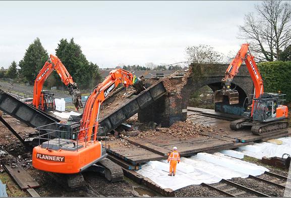
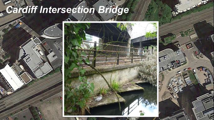
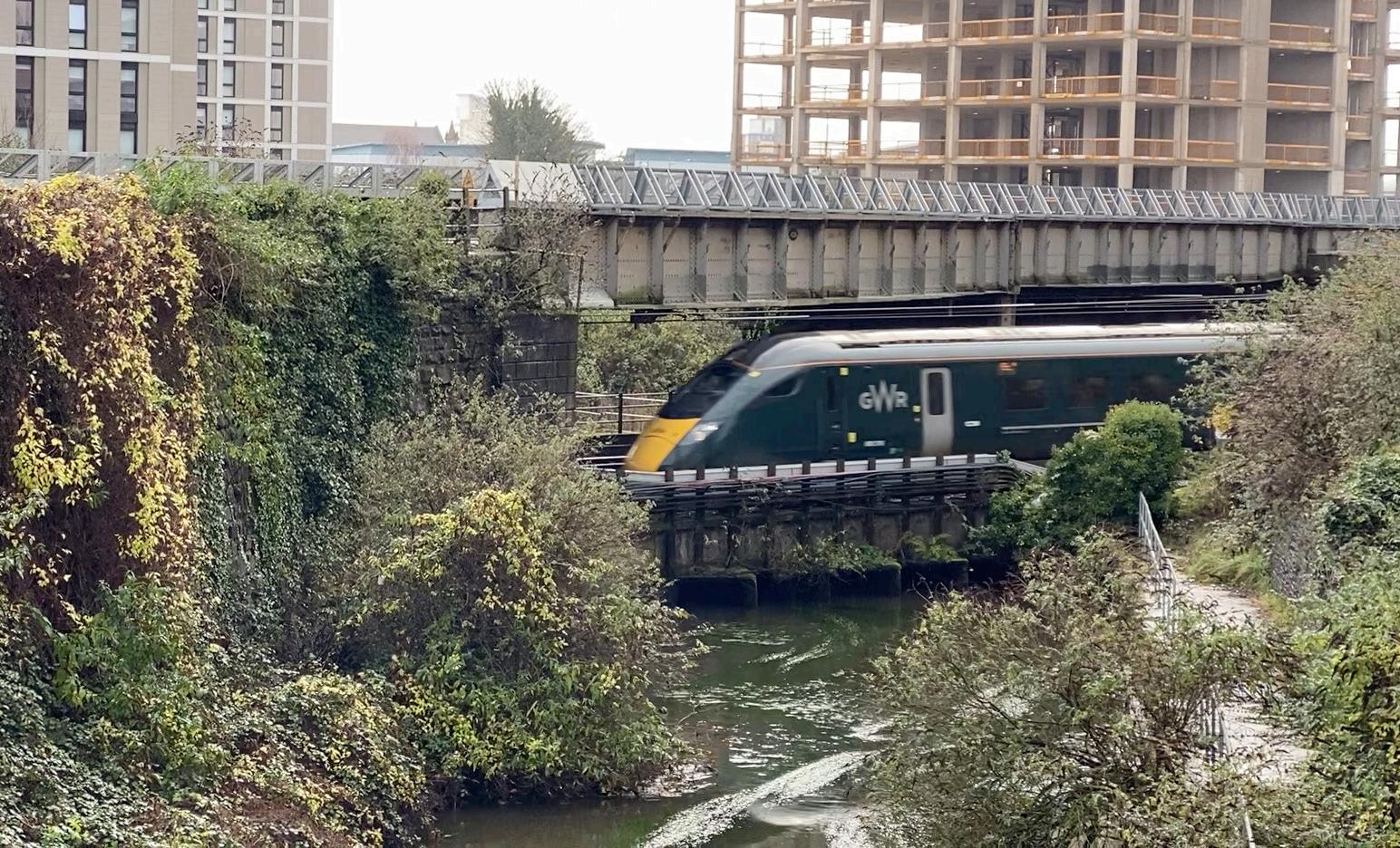
Figure 3: Cardiff Intersection Bridge - Cardiff Central Station approach, Wales and Western Route.
INTRODUCTION
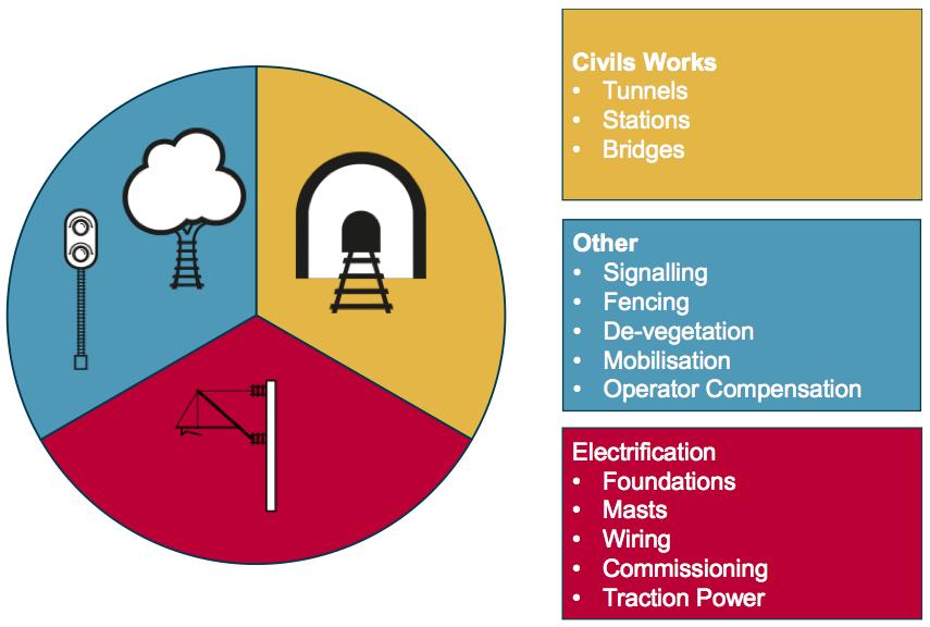
The cost of electrifying a railway can be expensive. In the UK the cost is often significantly more than European railways due to the restricted railway gauge used when the railways were first constructed in the early 19th century. This can result in the requirement to reconstruct bridges, to lower the track or both in order to achieve the necessary electrical clearances. Civil engineering works to provide electrical clearance can make up over a third of the total project costs (figure 1). Avoiding or reducing these costs can considerably strengthen the business case for railway electrification.
In Britain, the first option considered by overhead contact line designers is to reduce the system height and reduce the contact wire height from the nominal height of 4700mm to 4165mm. When this isn’t sufficient to achieve the required electrical clearance, the next options to be considered are to either reconstruct, demolish and renew the bridge or to lower the track or both. The aim of application of voltage-controlled clearances (VCC) is to avoid the above interventions, an example of which is shown in figure 2.
In Cardiff, on the Wales and Western Route, the Great Western Electrification Project [1] identified a particularly complex bridge located 400m from the end of the electrification scheme. The cost estimates for design and construction ranged between £40-50m due to the constrained site at the proximity of the station and junctions. The only other conventional option to allow electrified lines to pass under the bridge was to lower the track. The complex arrangements at the Cardiff Intersection bridge would require the rebuilding and lowering of the culvert carrying the water supplies to the former Bute dock, together with significant main-line track works at a cost of approximately £15-20m. The physical constraints above and below the Wales and Western mainline on the approach to Cardiff Central Station can be seen in figure 3.
REDUCING CLEARANCES
To enable electrification through to Cardiff Central Station without major civil engineering works, it was recognised that the contact line conductors would have to be placed as close as possible to the underside of the bridge thus minimising the physical distance and electrical withstand clearance from the contact line to the bridge. In addition, the design of the contact line through the bridge necessitated that the height of this was lowered which resulted in a reduced electrical clearance to trains that pass below it.
The risks associated with reduced electrical clearances can be described in a simple ‘bow-tie’ diagram. Figure 4 shows the hazards or threats, the prospective flashover to bridge event and the possible consequences of the flashover to the bridge. Figure 5 shows the hazards or threats, the protective flashover to the rail vehicle roof and the possible consequences of flashover to the rail vehicle roof. The recommended air gaps to achieve electrical clearances are published in BS EN 50119. These air gaps are based upon experience and take into account the probabilistic nature of the risk, effectively specifying functional insulation.
BS EN 50124-1:2017 provides the basis for insulation coordination, the methodology and the compliance criteria for dimensioning the creepage distances and electrical clearances compared to withstand voltages for railway applications. Insulation coordination requires that the stresses to which it may be subjected to over the anticipated lifetime are considered. These stresses include those associated with lightning transients, switching transients, switching harmonics on the train and any possible resonance interactions.
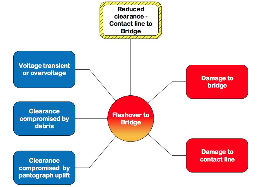
Figure 4: Reduced contact line clearance to bridge bowtie diagram. Figure 5: Reduced contact line clearance to rail vehicle or staff bow-tie diagram.
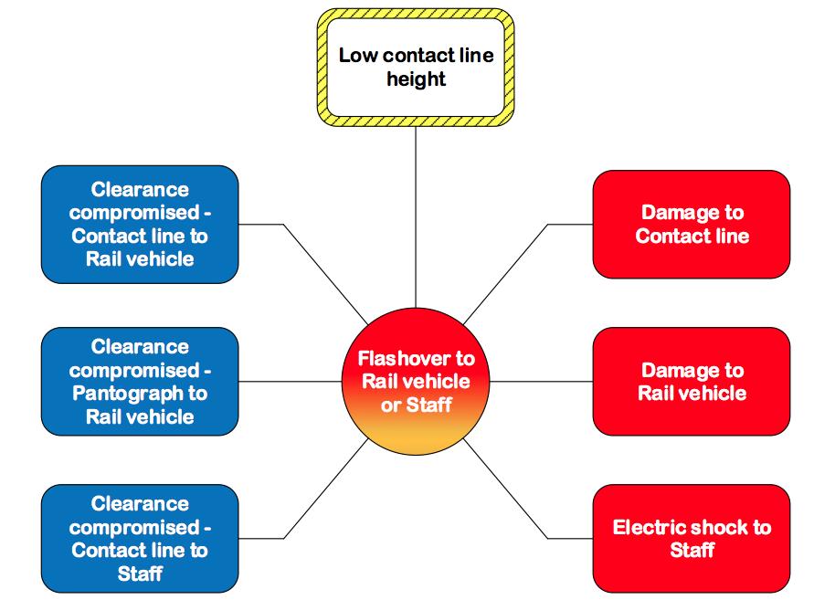
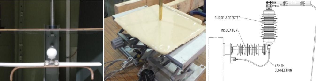
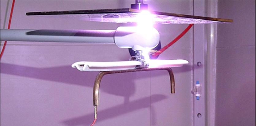
Figure 7: Flashover between insulated contact wire and earthed (non-insulated) plate.
For fixed installations, with a nominal 25kV (rated insulation voltage UNM of 27.5kV), the rated impulse voltage is 200kV (overvoltage category OV4 rating as per BS EN 50124-1:2017) and 170kV (overvoltage category OV3). OV4 category applies to circuits not protected against external or internal overvoltage, eg outside lines which can be endangered by lightning or switching overvoltage. OV3 category is the same as OV4 but with less harsh overvoltage conditions. For installations at the 200kV withstand rating and without specific protection against over voltages, the standard minimum clearance in air 370mm.
If the equipment of the contact line is not protected by a metal-oxide surge arrester against overvoltages, the dimensions of the physical clearances is determined by the intrinsic insulation of the contact line. The presence of a metal-oxide surge arrester can be used to reduce (ie, control) the magnitude of the impulse voltage such that the physical dimension of the clearance is in-turn controlled to a separation distance that is below that associated with intrinsic insulation.
A series of laboratory tests were commissioned to provide an evidenced based quantification of the effects of impulse voltage transients and power frequency overvoltages on electrical clearances. The tests included subjecting the contact wire and associated support assembly to lightning impulse voltages, switching impulse voltages and to power frequency overvoltage’s that would be expected in a railway environment.
Tests were conducted with and without protective measures. Protective measures included the options of introducing a metal-
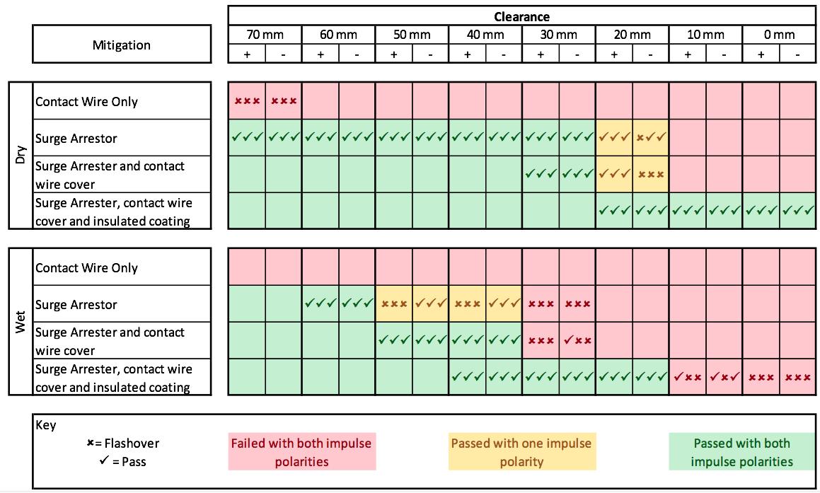
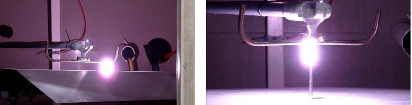
Figure 9: Flashover between contact wire and train roof (left), roof mounted aerial (right).
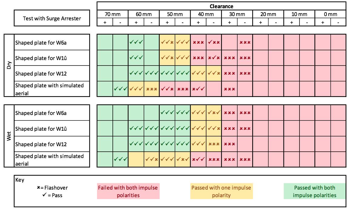
Figure 10: Lightning-impulse withstand test results – various train roof profiles.
oxide surge arrestor, PTFE contact wire cover, polyurea insulation coating of the earthed plate representing the bridge structure (figure 6).
Tests included a comparison between a conventional contact line support arm and a stress graded contact line support arm that was specifically developed for installations under a bridge or tunnel.
The insulated contact wire cover has been used on the GB railway in reduced clearance areas to avoid flashovers caused by birds sitting on the contact line. The polyurea coating also has service experience and has been used mitigate against the effects of touch voltages. Metal-oxide surge arresters have been installed and gained service experience on the BahnDanmark network. The principal aim of these tests is to provide quantitative evidence on the effectiveness of the protective measures and in particular the effectiveness of the metal-oxide surge arrester.
For the series of tests, all parts of the under-bridge arm fitting and any attached secondary insulation, were coated in a pollution mix. The pollution was created using a kaolin-salt mix prepared according to the BS EN 60507.
Each arrangement was tested in both dry and wet fog conditions. The wet fog conditions were created within a 15m3 environmental chamber by injecting de-mineralised water with a conductivity of 4 μS.cm-1 at a rate of 4.5 litres per hour using compressed air at 6 bar through two humidifier nozzles placed in the floor of the chamber. The wet fog conditions were applied for a 30-minute duration to allow for full wetting of surfaces before voltage was applied. BS EN 50124-1 does not specify the requirement to carry out the testing in wet conditions or for pollution to be applied. The tests specified, however, were included so that the environmental condition that the contact line will be expected could be systematically tested.
For the impulse voltage tests, an impulse test voltage Ui of 193kV was selected from Table A.8 of BS EN 50124-1. The tests comprised at least three positive polarity and three negative polarity impulses in accordance with the BS EN 50124-1 test acceptance criteria. Figure 7 shows a disruptive discharge of one test with an earthed plate in dry conditions. The results of the lightning-impulse withstand testing are detailed in figure 8.
The tests show that a 100% withstand can be achieved at a 60 mm physical clearance with the application of a surge arrester to provide the protective measure. The physical clearance can be further reduced to 20mm with the application of the metal-oxide surge arrester, insulated wire cover and the polyeurea coating on the bridge structure.
The tests provide evidence that the physical clearance between energised components of the contact line and earthed structures such as the underside of bridges can, with a range of practical protective measures be reduced to as little as 20mm. This represents a significant improvement when compared to the standard dimensions required to achieve electrical clearances.
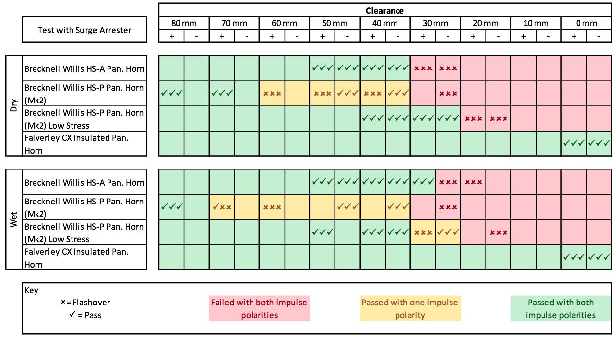
Figure 11: Lightning impulse withstand tests results – pantograph to train roof.
REDUCED CLEARANCES TO RAIL VEHICLES
In locations where the electrical clearance is restricted, such as Cardiff Intersection Bridge, the height of contact wire is often specified to be lower than the GB nominal height of 4700mm for open-route track. The minimum height for the contact wire on the GB railway network is 4165mm.
The minimum wire height of 4165mm provides a theoretical 200mm distance between the contact wire and the train roof. This does not provide a sufficient air gap between the contact line and the rail vehicle to be rated as basic insulation. In this case, it is reasonable to specify functional insulation based on the probabilistic nature of this parameter (ie the likelihood of a transient occurring when a train present is considered unlikely). train roof, as this would have reduced the conductivity of the earthed metal components representing the train roof.
Figure 9 records examples of flashovers between the contact wire and the train roof and between the contact wire and a roof mounted aerial. The results of these tests (figure 10) provide evidence that the physical distance between the contact wire and a rail vehicle could be reduced to 70mm.
For rail vehicles with a pantograph, it was necessary to understand and quantify the risk of flashover from the pantograph horn to the roof well. Again, similar testing was carried out, this time with a selection of pantograph horns representing a wide range of the types in service in the UK along with an insulated pantograph horn as a control measure.
The actual cross-sectional profile of railway vehicles, with fitted equipment, varies considerably, and the diversity of these would be onerous and time consuming to test. The tests were therefore focussed on a range of profiles that represent the most common profiles to the most onerous in terms of electrical stress. A train roof profile with the addition of a 100mm long, 10mm diameter rod (simulating a roof aerial) was used to maximise electrical stress and represent a realistic worst-case train roof profile.
Testing was carried out to the same specification as the reduced clearances tests, although the pollution mix was not applied to the The test results of these tests are shown in figure 11. The tests provide evidence that the physical clearance between the pantograph and the train roof can be reduced to between 60mm and 70mm. These tests justify reducing the wire height from 4165mm to 4100mm, representing a reduction of 65mm.
This small reduction, in combination with the other tests, provides an evidenced based approach that the protective control measures and the lowering on the contact wire height allow the bridge to be wired, without the need to undertake major civils works. The lowering of the contact line will however require additional control measures to
be applied including additional warning signage and publication of notices advising of the lower contact line height. This, in conjunction with the protective measures and existing working practices will contribute to maintaining workforce safety.
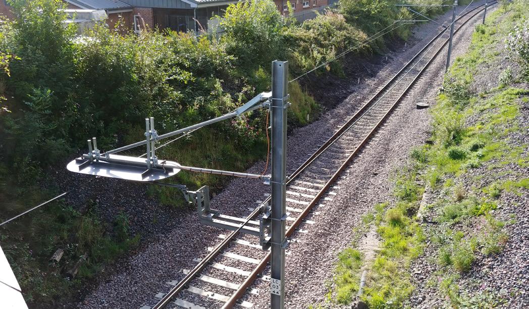
FROM THEORY TO PRACTICE
The test arrangement of a surge arrester (with surge counter) and steel plate with the polyeurea insulation coating was initially trialled on the Scotland Route (figure 12). In these tests, the air clearance between the contact line and the insulated plate was reduced in stages to an air clearance of 50mm. The tests provided invaluable in-service experience and proved that the concept of the voltagecontrolled clearance can be applied to the operational GB railway.
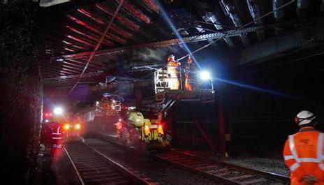
Following the trial on Scotland’s Railway Region, Network Rail gained approval from the RSSB to develop the voltage-controlled clearance concept for Cardiff Intersection Bridge. The installation of the insulating coating to the underside of Cardiff Intersection bridge is shown in figure 13 and the Class 800 (IET) travelling ‘under the wires’ is shown in figure 14.
The total cost of the development (including laboratory tests) and the installation was less than £1 million. This represents a significant saving when compared to the £40-50m estimated cost of reconstruction. The route is able to accept all standard rail vehicle gauges despite the reduced clearance of 40mm from the contact line system to the underdeck of the bridge.
The line to Cardiff was energised in December 2019 and has worked perfectly without any disruption form flashovers. This has evidenced that the concept of surge arresters, insulating coating and contact line covers as part of the voltage-controlled clearances (VCC) to be viable and one which is capable of being used on future electrification projects across the network.
As for ongoing maintenance and inspection, the application of contact line covers is an established one and will follow established practices. The surge arresters are fitted with an expulsion fuse device that disconnects the surge arrester in the event of a highenergy fault and provides a visual indication of such an event whilst keeping the traction supply energised. In addition, the surge arrester installations are fitted with a surge monitoring device that can monitor the number of surges and the surge arrester leakage current (which provides an indication of the surge arrester health) and this data can be accessed remotely. Coupled with an inherently high mean time between failures (MTBF) for surge arresters, these features will form part of the ongoing inspection and maintenance requirements for surge arresters. Each of the above along with a visual inspection of the bridge underdeck will be carried out as part of the routine inspection regimes.
CONCLUSIONS
The application of the insulated contact line cover, the polyeurea insulation and the metal-oxide surge arrester have been installed on railways within Great Britain and Europe.
This article provides details of tests carried out in a high-voltage laboratory and the successful application of the voltage-controlled clearance (VCC) concept on the GB operational railway.
The tests provide an evidence-based approach to determining how these protective measures can be used as a method to control the relationship between physical clearance and the 100% electrical withstand value for basic insulation. By taking an electrical view of clearances, we have been able to increase the dielectric withstand level from functional insulation (rated impulse voltage UNi≥145kV) to basic insulation (rated impulse voltage UNi=200kV) whilst reducing the air gap between live components and earthed metal work. This removes the need to consider any probabilistic element of a risk assessment and application of voltage-controlled clearances (VCC) therefore simplifies the overhead line design process.
Initial design studies for future electrification schemes using the voltage-controlled clearance methodology developed for Cardiff Intersection bridge indicates an expected reduction of more than 40% in the number of bridges requiring re-construction during future electrification schemes. This opens up the exciting prospect of enabling routes to be electrified where this was previously deemed to be uneconomic. The installation and subsequently successful operational experience of surge arresters, insulating coating and contact line cover paves the way for similar technologies to be installed on many other situations on the network.
The work at Cardiff Intersection bridge has the tangible prospect of playing a pivotal role in making electrification more financially viable and supporting decarbonisation of the railway.