17 minute read
Longitudinal bearer systems in Network Rail: The past, present and future in a nutshell

by The PWI

Longitudinal bearer systems in Network Rail:
The past, present and future in a nutshell
Advertisement
AUTHOR: John Nelson
John Nelson is the Principal Engineer for Competence and Capability for Permanent Way in Network Rail’s North West and Central Region. John is also Chairperson for the Longitudinal Bearer System Community of Practice and has fourteen years’ experience in Network Rail in Asset Management, Maintenance, Infrastructure Projects, Assurance and the Technical Authority. He is a Chartered Engineer with the ICE and most passionate about improving access to learning in the railway to improve the competence, and ultimately the safety, of all railway colleagues.
SUPPORTING AUTHOR:
Dr John Williams
In writing this article John was supported by Dr John Williams of RSK who has over 20 years’ experience in wood science and holds a PhD in timber preservation. He specialises in the inspection and evaluation of structural timber in safety critical applications.
INTRODUCTION
Longitudinal bearers, also known as longtimbers, wheeltimbers, and composite baulks amongst many other names, appear to be very simple when considering basic railway engineering principles. However, in practice, they are more complex. Furthermore, because of the variability in their dimensions, loading, support arrangements and material properties, they can present a challenge to inspect, maintain and replace.
A longitudinal bearer comprising softwood or hardwood timber, or a Fibre-reinforced Foam Urethane (FFU) will sit atop a structure and is held in situ by cleats, holding down arrangements, transoms, ties and other physical restraints to prevent vertical and horizontal movement. The longitudinal bearer will sit underneath and parallel to the rail and is designed, just like all track support systems, to provide safe guidance and support to railway vehicles. The nuance of longitudinal bearers compared to traditional track is the absence of ballast and the direct transfer of forces from rail to the structure via the longitudinal bearer.
Longitudinal bearer systems (LBS) are generally defined as being a pair of longitudinal bearers together with all the fixings between bearers, the holding down arrangements, connections with the supporting structure, rail support arrangements and transitional arrangements. From the outset it is important to appreciate two key features; the longitudinal bearers are only a part of the system and there are a great number of variables which mean that almost every system is bespoke. However, almost all longitudinal bearer systems operate on similar principles and there are some common similarities that support the engineer in understanding key risks and areas to examine.
In some cases where the longitudinal timber is fully supported, for example, on a steel deck or in a trough, the load transfer will simply be vertically through the timber. However, in other situations, where the longitudinal bearer is spanning, that is to say there is a gap between the supports on a cross girdered bridge, then loads will be transferred longitudinally through the timber to the structural supports. These different support arrangements mean that not all longitudinal bearers present the same risk, and some will have more failure mechanisms than others. In cases like the bridge at Lower Hall in the Wales and Western Region the longitudinal bearers have been cast into the structure in concrete, reducing the risk of lateral movement but hindering the inspection process and increasing the cost and complexity of replacement.
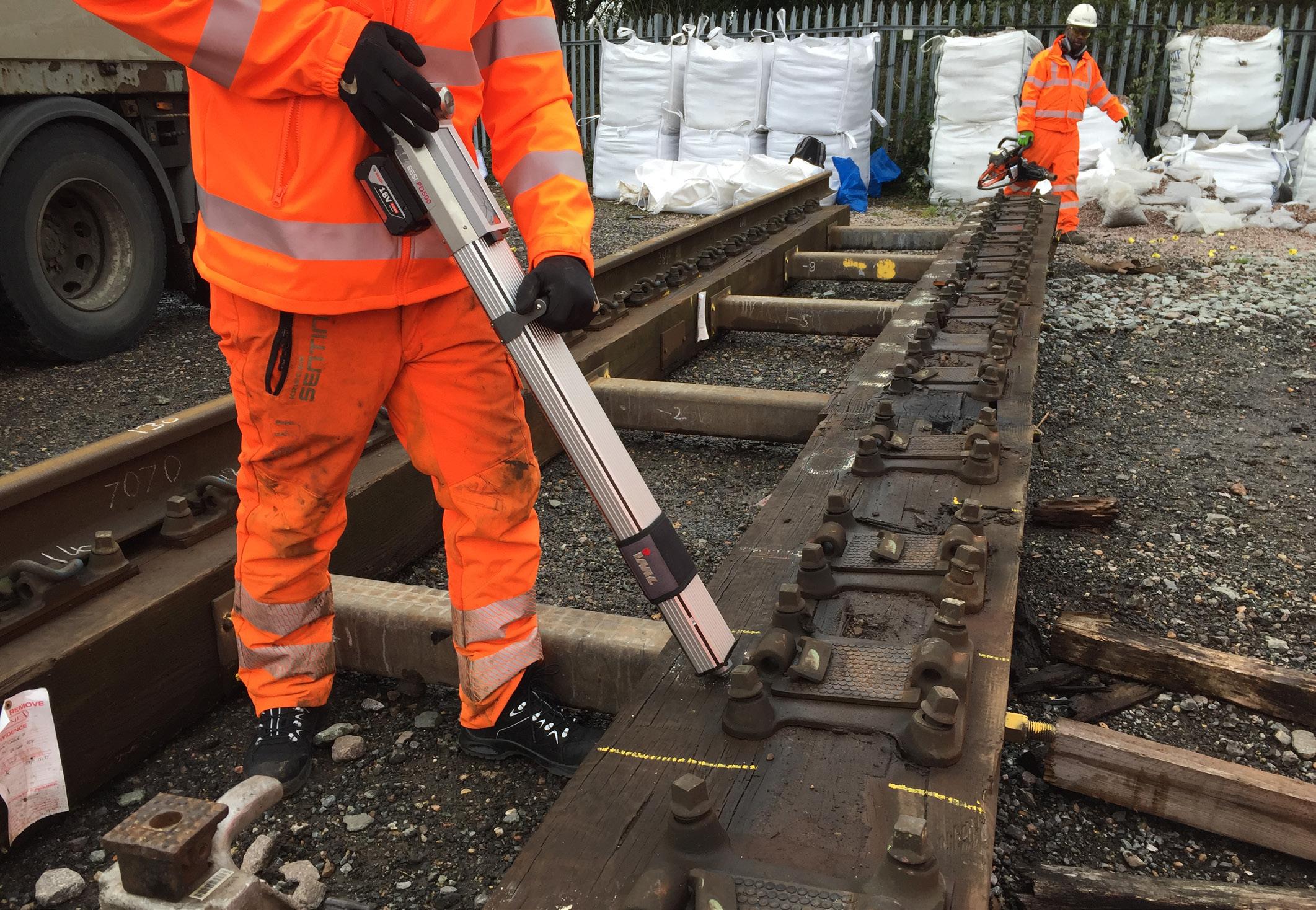
Figure 1: The IML Resi-PD 500 in use on longitudinal bearers removed from track following the derailment at Wanstead Park.
This paper provides some background information on longitudinal bearers (the past), discusses recent developments in the effective management of these assets (the present) and looks into the research which will deliver a step change in predicting the line expectancy of these high risk, variable and often complex engineering systems (the future).
THE PAST
Longitudinal timbers were generally installed on structures where either the construction depth, or the foundation limits prevented the use of ballasted track, or where there was a requirement for a more rigid track alignment. The material used for longitudinal bearers provides some flexibility and resilience when compared to directly fixed track in concrete or steel using specialist baseplates. In addition, there are some other benefits and challenges from different material types summarised in Table 1.
FFU bearers will clearly play a significant part in future longitudinal bearer assets. However, because current experience of FFU use is limited this article will focus on the current and future management of timber arrangements. Across the infrastructure that Network Rail operates there are around 13,500 longitudinal timbers and these are spread across all regions and routes, but not equally. One of the challenges facing the inspector and maintainer in areas where there are only a handful of longitudinal bearers is maintaining relevant skills and knowledge. Colleagues with many years’ experience are retiring and opportunities to develop new experience are limited because detailed examinations often only take place annually. Furthermore, the population of these assets is reducing because asset policy dictates that new bridges are installed without longitudinal bearer systems.
Nonetheless, there are some circumstances where it may be desirable to install longitudinal bearers. For example, where a robust cost benefit analysis demonstrates that there is no other suitable and affordable mechanism for track support, or where the longitudinal bearers are being replaced on a like for like basis without any structural adjustment. Another challenge that is often overlooked is that longitudinal bearers most often work as part of a multidisciplinary system. It is critical to ensure that the maintainer and inspector understand the relationship between assets, the impact that a deficient timber can have on structural components and also the benefits that will come from working collaboratively on inspection, maintenance and renewal. Examples of this are where permanent lower-level GRP (Glass Reinforced Plastic) decking has been installed alongside a long timber bridge to allow structures and track colleagues to perform detailed examination and maintenance on Bridge 8 and 9 on the Up Windsor Slow at Wandsworth Town, and the recent replacement of timber boarding for open grillage GRP decking on the Manea bridges on the Anglia route.
Finally, the hazard caused by internal decay is prominent for two reasons, firstly Network Rail, for many years, has struggled to identify internal decay accurately, and secondly, once identified, the impact that varying sized pockets of decay may have on the ability of the timber to undertake its intended purpose is not fully understood. The impact of these deficiencies was felt most forcefully when an Intercity 125 train derailed at Paddington Station on 20 August 2017, a heavily loaded freight train derailed near Wanstead Park station on 23 January 2020 and at numerous other incidents where lines were deemed unsafe for traffic upon discovery of large pockets of internal decay.
Fortunately, the last 18 months has seen positive developments with new technology for the detection of decay, improvement in inspection and collaborative working, new training and also the full product approval of FFU as a replacement for pressure treated softwood bearers.
THE PRESENT
The re-publication of NR/L2/TRK/3038 titled ‘Longitudinal Bearer Systems – Inspection, Maintenance and Design’ in March 2020 has provided a framework for better asset decisions to be made through better communication to and between key parties, and better recording of inspections. The former of these changes has
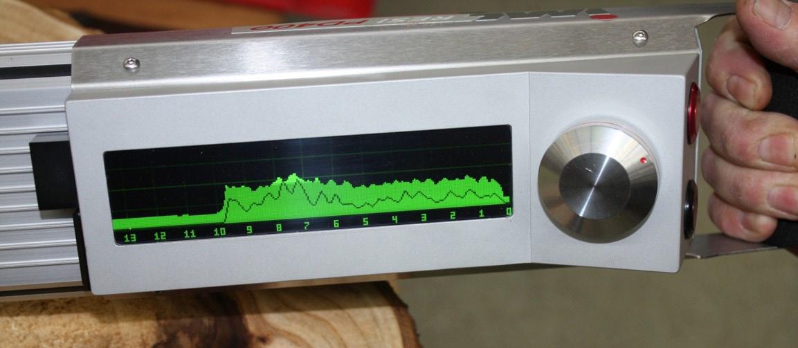
Figure 2: The live display of the IML Resi-PD 500. Photo - Sorbus International Ltd.
been achieved through mandating that a meeting between the person accountable for the safety of the line, the person responsible for delivery of work, and the person responsible for the inspection happens after each detailed examination. This means that the Track Maintenance Engineer (TME), the Section Manger and the Detailed Examiner respectively will sit and discuss all the available evidence on current timber condition and agree the life expectancy, and any other work or mitigations that should happen before the next examination. This brings to the fore the historic tension between the life expectancy and the planned replacement date (as an example) in addition to providing a platform for the Detailed Examiner to discuss their issues and concerns.
The better recording of inspections has been achieved through a templated approach to the longitudinal bearer management plan (LBMP) which now includes prompts to identify hidden elements, special characteristics of the longitudinal bearer systems and, critically, ownership of key assets like cleats, and their inspection regime. Historically, this boundary has previously been ill defined and this has hindered or neglected effective asset management.
The most significant of the changes made to TRK/3038 was to mandate that non-destructive testing (NDT) shall be undertaken on all longitudinal timber assets to understand the internal condition of the timber by identifying and evaluating the size of internal decay pockets and their potential effect on serviceability.
Decay is a particular concern for Network Rail because a significant proportion of the longitudinal timber bearers across the network comprise Douglas fir (Pseudotsuga menziesii). Historically, the rail industry has used Douglas fir imported from North America which has subsequently been pressure treated with creosote. More recently, Douglas fir tends to be sourced from UK forests. However, UK grown Douglas fir is not as resistant to decay. This vulnerability has been exacerbated by changes in timber preservative legislation which has seen restrictions on the formulation and use of creosote. Furthermore, additional legislation has resulted in the withdrawal of CCA (copper-chromium-arsenic) formulations.
Consequently, there are an increasing number of longitudinal bearers comprising UK grown Douglas fir that have been installed in the infrastructure which tend to deteriorate faster. This may be exacerbated by less effective preservative formulations.
Alongside the instruction to undertake NDT of longitudinal timber assets, a new tool, the IML Resi-PD 500 micro drill system (figures 1 and 2), has been introduced to the rail network to support detailed examiners in taking consistent recordings to identify and analyse decay in timber. The advantage of the IML Resi PD 500 is the elimination of assessor subjectivity, the simplicity of the tool, the live results display and the WoodInspector™ software that ‘calculates decay’ to support effective examination. For these reasons and after an extensive product review and acceptance process the IML Resi-PD 500 has been demonstrated to be the most appropriate tool for Network Rail when compared to others on the market like the Rinntech Resistograph®, the Sibtec decay detection drill and manual attachments for a standard cordless drill.
The IML Resi-PD 500 is a modern form of decay detection drilling which measures and records the resistance of the timber to the penetration of a fine drill bit into the timber. The drill bit has a cutting head diameter of 3mm and a needle shaft diameter of 1.5mm. The device is so named to include the manufacturer, Instrumenta Mechanik Labor System (IML), then Resistance Power Drilling (ResiPD). The maximum distance that can be measured in one drilling is 500mm which is sufficient to inspect longitudinal bearers.
A softwood longitudinal timber in good condition, will offer a high resistance to rotation and feed of the drill bit, whereas a heavily decayed longitudinal timber will have a much lower resistance. This resistance is measured by the drill and then plotted along an axis as a ‘signature’ for that particular location in the longitudinal timber so that it can be interpreted by an examiner and engineer. It is worth noting that the drill settings allow a variety of rotation and feed speeds from 1,500 rpm to 5,000 rpm and 25cm/min to 200cm/min respectively. These settings allow a user to tailor the IML Resi-PD 500 to the type of wood being assessed, be it a hardwood such as ekki (Lophira alata) or UK grown Douglas fir. Other useful features for examiners and engineers are the live display screen allowing instant review and analysis, WoodInspector™ software to support consistent evaluation of internal decay, Bluetooth compatibility with a smartphone app and inbuilt systems to detect drilling needle bluntness, drilling angle and cavity detection.
While the introduction of the IML Resi-PD 500 has undoubtedly improved our understanding of asset condition by giving an examiner a repeatable and reliable ‘x-ray’ view into the internal condition of the longitudinal bearer it has also raised some challenges, namely how to target the drilling to identify decay and how to analyse the results.
A number of techniques for employing the drill have been considered. These include interval drilling at set distances and also targeting drilling to areas where evidence suggests there is an internal decay pocket. The advantage of interval drilling is that it provides an indiscriminate baseline of timber condition which can be used to record timber condition over a long period, the disadvantage of course is that this approach could completely miss decay in a timber if the drilling location doesn’t coincide with an area of decay. A complementary approach would be to take multiple drillings at each baseplate and critical areas of the timber guaranteeing that decay would be identified. However, this can add substantial extra time to the examination, additional time to analyse data. Limits on data storage can also influence drilling frequency. The internal data
storage capacity of the IML Resi-PD 500 is limited to a cumulative total of 90m of drilling. Other factors such as battery life and needle wear also need to be considered.
After extensive engineering trials a procedure has evolved which uses a targeted approach to use all available data to identify areas of concern. This includes a detailed visual inspection using a bradawl to probe the surface of the timber for softening, looking for evidence of baseplate shuffle and/or indentation and the knocking and tapping of baseplate screws to identify any movement or looseness. There is also a review of dynamic track recording to identify gauge and other track top and alignment faults and a review of historic reports and previous inspections. This information is then considered by the examiner alongside the type and age of the timber and its structural role in the system to enable them to target areas of decay, and those positions of critical structural importance for assessment using the IML Resi-PD 500. Where decay is detected, multiple drillings are undertaken to evaluate the size and shape of decay pockets. The best analogy for this is to imagine playing a three-dimensional game of Battleships, an examiner would use any available information to start ‘dropping bombs’ around the area they suspect to find decay, then once identified they can continue to drill until the volume of decay is properly understood.
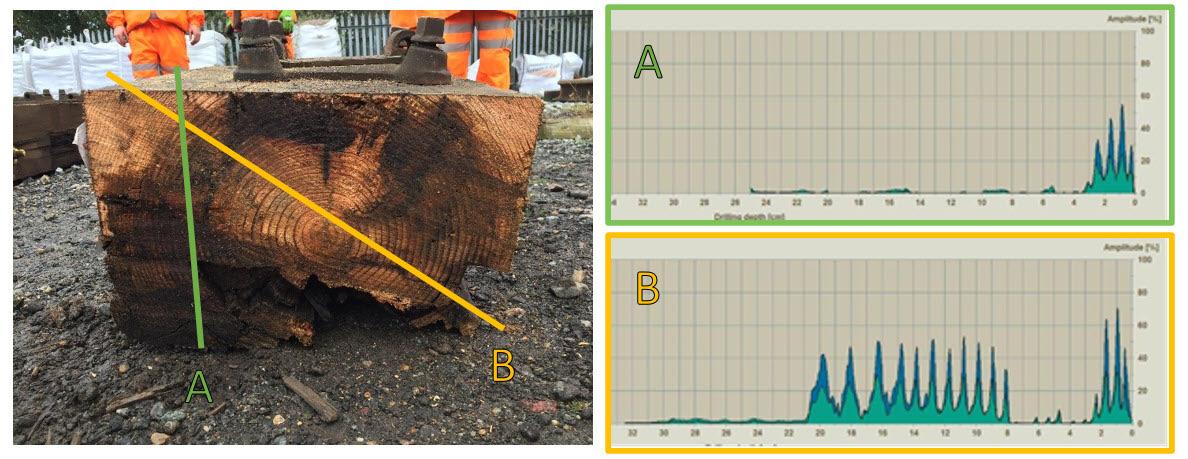
The WoodInspector™ software installed onto every drill will support the examiner by doing analysis of the resistance to automatically highlight areas of suspect decay, where the resistance is less than 5% of the maximum drilling amplitude (ie the y-axis) for more than 10mm. The extensive training that Network Rail is rolling out for the detailed examination of longitudinal bearers provides examiners with the knowledge and skills required to verify this. The graphs in figures 3 and 4 gives a good representation of how the IML Resi-PD 500 displays the data and how invaluable it can be to an examiner. These timbers were dissected following the derailment at Wanstead Park in January 2020 so the opportunity was exploited to further test the IML Resi-PD 500 as part of the Product Acceptance process.
The standard output graph from the IML Resi-PD 500 has a few features to understand; the x-axis is the drilling depth in centimetres (the drilling starts from the righthand side), the y-axis is the amplitude (i.e. the measure of the resistance of the material) the green chart is the resistance to rotation and the blue chart is the resistance to the feed. The sawtooth pattern is a product of the difference in hardness of the earlywood (fast growing) and late wood (slow growing) that makes up the annual growth rings of the tree. Where there is decay, the resistance falls away to nearly zero and the graph trace “flatlines”. The path of the drill is overlaid onto the cross section of the timber. However, some slight anomalies can be explained because the drilling was taken in this approximate location rather than exactly on the cut line. When reviewed in detail the four output graphs are examined to show:
A. The drill meets with ‘sound wood’ as represented by the sawtooth patten on the righthand side of the graph however after around 4cms the wood is severely decayed through to the end of recording at 25cms as evidenced by the ‘flatline’ trace.
B. In this case the drill meets with sound wood to start but then meets some decay, then through the rings of sound wood, past the pith and then heavy decay from 25cms onwards.
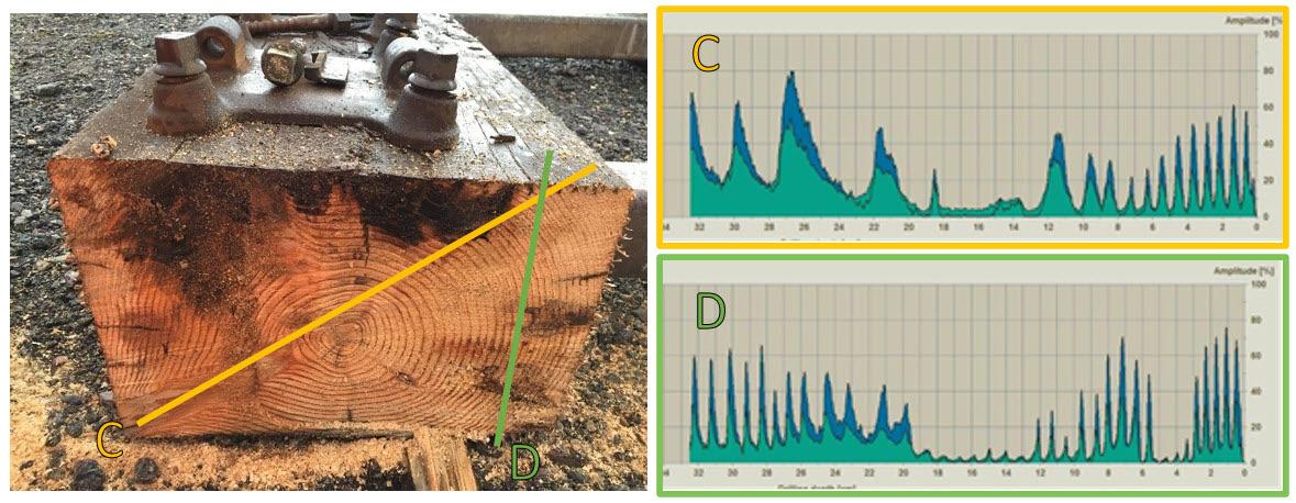
C. The area of interest here is the knot measured between 20 and 32cms which has distorted the growth ring pattern and resulted in a wider ‘sawtooth’ pattern on the trace, and the close proximity to the pith, characterised by low resistance, is noteworthy at around 16cms.
D. The pattern displayed between 15 and 18cms is most interesting because it is most likely that the IML Resi-PD has either followed the path of one of the rings of the timber or passed through an area of decay. The drop in resistance and the slight sawtooth pattern indicates that there is still some structure to the timber. Repeat drillings at different angles in the same locations would determine if the low resistance is due to decay or passage of the drill around the earlywood portion of the growth ring.
Using the IML Resi-PD 500 has helped Network Rail to make a step change in the condition assessment of longitudinal timbers to understand where decay exists, and now attention is firmly focused on understanding what that means for asset life and effective asset management.
THE FUTURE
In partnership with Dr John Williams, RSK’s Principal Consultant with over 20 years’ experience of wood science, Network Rail is about to embark upon a project to mathematically model decay in longitudinal bearers in different loading scenarios and environments. This modelling will provide a proof of concept that can be developed to ultimately enable robust condition categories for longitudinal bearers and further develop and refine the Failure Modes and Effects Analysis (FMEA) undertaken into longitudinal bearer systems so that precursors to failure can be identified and accurate life expectancies of assets can be better predicted, and managed.
The methods available to life-extend timber assets have been limited in recent years since legislative prohibitions have been applied to effective treatments such as boron rod, creosote and copperchromium-arsenic containing formulations. Whilst these methods have been used to great effect in the railway for many years the opportunity to try new products must be grasped, as it is likely that the restrictions on using the traditionally applied products will remain in place.
As work progresses on the modelling of longitudinal bearer strength there is a clear need to use available products to slow down or stop decay in timber. To this end a series of preservatives have been researched to identify the most suitable for railway application based on use class, environmental concerns, temperature variation and method of application. Trials are about to begin using borate containing gel formulations applied to softwood longitudinal timbers through holes drilled in areas where decay has been identified (figure 5). The boron gel is water soluble and will diffuse throughout the timber over time to prevent further proliferation of decay within the longitudinal timbers. Whilst this will never restore the full original strength of the longitudinal timber, it will at the very least maintain the current condition, and in many situations, this will be enough to extend the expected life expectancy of these critical assets.
SUMMARY
It is certainly the case that each longitudinal bearer system is bespoke, and that some systems are far more complex than others, and also that timber is a variable material that can be hard to evaluate and predict – especially when working with limited data. But that does not mean that longitudinal bearer systems have to be hard to manage.
Network Rail is on a journey to better understand longitudinal bearer systems and the introduction of new technology like the IML Resi-PD 500 micro drill system and the research project into decay will help to identify and predict rates of growth of decay in future. Getting this right will be a game changer in the management of these high-risk assets.
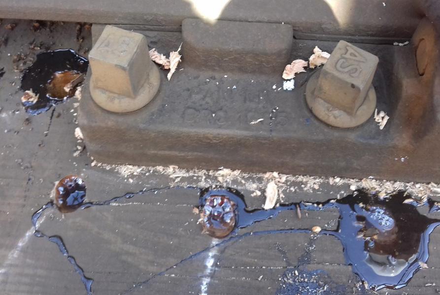
Figure 5: A boron based preservative gel installed into a longitudinal bearer in situ (actual hole size and spacing exaggerated for illustrative purposes and must not be used as a basis for undertaking treatment). Photo - Dr John Williams.