


PWI ANNUAL MEMBERSHIP £86 4 ISSUES OF THE JOURNAL ANNUALLY (£15.00 PER ISSUE FOR NON MEMBERS) VOL 139 PART 1 JANUARY 2021 CLEANING UP OUR ACT DIGITAL TECHNIQUES AND FIRST-PRINCIPLES DESIGN: CHALLENGING ELECTRIFICATION COSTS DYNAMIC INSPECTION OF GREAT WESTERN OVERHEAD LINES PRACTICAL INTEGRATION OF AUTOMATED OPERATION IN RAILWAYS: A SYSTEM OF SYSTEMS PERSPECTIVE SETTING THE STANDARD FOR PANTOGRAPH GAUGING: AN ENGINEERING JOURNEY UNDERSTANDING POLYMER RAILWAY SLEEPERS 10 22 12 26 38 42 THE PWI: ON BOARD WITH ELECTRIFICATION 1
The 2021 Journal has been designed with a new, enhanced technical focus that pays tribute to the PWI’s longstanding tradition of being the home of technical content and knowledge sharing for the rail infrastructure industry. In this issue, you will find a far greater number of technical articles, while our community pieces now feature online.

We really hope you enjoy this change!
Kerrie Illsley - Creative Manager journaleditor@thepwi.org
SECTION MEETING REPORTS CENTRAL TEAM UPDATES BOARD MEETING MINUTES COMMUNITY ARTICLES...
2
2021 PWI ANNUAL SUBSCRIPTIONS

INDIVIDUAL MEMBERSHIP
Apprentice, Student £0 e-Journal £25 printed Journal
Member £86.00
Member(66 or older at 01.01.21) £35.00 EngTech Member* £86.00 IEng/CEng Member* £137.00 Fellow £115.00
Fellow (66 or older at 01.01.21) £46.00 EngTech Fellow* £115.00 IEng/CEng Fellow* £182.00

CORPORATE MEMBERSHIP
Sml enterprise (Turnover up to £17.5m pa) £2,140 Med enterprise (Turnover £17.5m - £200m pa) £5,350 Lrg enterprise (Turnover above £200m pa) £10,700 Heritage railway £150
PROFESSIONAL REGISTRATION
APPLICATION FEE: New Registrant** EngTech £60 / IEng £225 / CEng £225
APPLICATION FEE: Additional Membership EngTech £40 / IEng £90 / CEng £90
EngCouncil Fee* EngTech £19.90 / IEng £34.70 / CEng £40.90
* If you are professionally registered through the PWI the annual Engineering Council Registration fee will be collected in addition to your PWI subscription and will be paid to the Engineering Council on your behalf. ** Includes the Engineering Council Registration Entry fee.
Apologies
There was a mistake in the October Journal! We’re terribly sorry about this. Charles Burn won first place (not second) in the Young Achiever Awards. The correct version of the article can be found on our new website.

CONTENTS 4 A focus on the true technical 6 Climate change, decorbinisation and engineering 7 Industry resilience 8 PWI technical seminar Electrification: Delivering the business case 10 Cleaning up our act 12 Digital techniques and first-principles design: Challenging electrification costs 16 Saving the planet: The Engineer’s challenge 18 Rail Link to Kashmir Valley 22 Dynamic inspection of Great Western overhead lines through a novel concept of the Internet of Intelligent Pantographs 26 Practical integration of Automated Operation in Railways: A system of systems perspective 36 The advantages of electrified railways: An international summary 38 Setting the standard for pantograph gauging: An engineering journey 42 Understanding polymer railway sleepers 47 Traction Power Supplies Not another PSU 50 Network Rail track renewals online seminar 54 Andy2 on resilience 56 The new PWI website 60 Professional registration 62 PWI Training 64 PWI technical seminar - Plant and machinery: Support to rail infrastructure renewal and maintenance for the 2020s and beyond 66 Our people 68 Corporate Members and Technical Board 70 Section contacts 72 PWI technical seminar - Hit the north: Insight into upcoming railway infrastructure developments in the North 74 Knowledge Hub THE JOURNAL JANUARY 2021 VOL 139 PT 1 THE COPY SUBMISSION DEADLINE FOR THE NEXT JOURNAL IS 1 FEBRUARY 2021 FRONT AND BACK COVER IMAGE: Lawrence McEwan MPWI Principal Construction Manager - Network Rail COPY / ADVERTISING DEADLINES & ENQUIRIES April 2021 DEADLINE 1 February 2021 July 2021 DEADLINE 1 May 2021 October 2021 DEADLINE 1 August 2021 January 2022 DEADLINE 1 November 2021 Kerrie Illsley, Creative Manager, journaleditor@thepwi.org
WAY INSTITUTION PWI
Box
230
/
secretary@thepwi.org PLEASE NOTE: Every care is taken in the preparation of this publication, but the PWI cannot
Publishing and layout by Permanent Way Institution
THE PERMANENT
Central, PO
12890, Brentwood, CM14 9RY +44 1277
031
www.thepwi.org /
be held responsible for the claims of contributors nor for the accuracy of the contents, or any consequence thereof. ISSN 2057-2425
3
A focus ON THE TRUE technical

ELECTRIFICATION

I hope you enjoy the theme for this Journal, which is “electrification” for two reasons; firstly, because it is such an important agenda item for UK decarbonisation, and secondly, because the PWI is now the Institution for electrification as well as track and structures.
When we electrify the railway, we need to consider all those key technical areas that we as pway engineers are familiar with, from geotechnics to track curving and fixity through to the tricky subject of… wait for it… clearances. See Phil Holbourn's presentation Very reduced Electrical Clearances (images 1 & 2) at the PWI South and West Wales Section meeting on 9 November 2020 you'll find this on YouTube.
REFLECTION
With almost a year of limited personal social interaction due to Covid-19, the PWI has been remarkably successful in enhancing our technical services to Members and I thank you all for staying with us and contributing to shared knowledge.
It seems to me that many people have gained possibly more than expected through the opportunity of virtual training and a vast variety of technical presentations. It has been a good period for online national events with the Automated Railways Seminars that took place on 17 September and 8 October in conjunction with IRSE, IET and IMechE, ably organised by Andy Packham. Network Rail continued with their halfyearly Technical Engineering Conference for Capital Delivery on 30 September. Both were very well attended with excellent speakers.
The last PWI full in-person event was Manchester’s excellent NW Seminar in March 2020, which will be succeeded by the event “Hit the North” later this year, hopefully as a blend of in-person and virtual.
4
Brian Counter TECHNICAL DIRECTOR technicaldirector@ thepwi.org

SUPPORTING THE INDUSTRY
The PWI is in a superb position to support the industry as we bring our professionalism in track, structures and electrification together through meetings, seminars, training and publications. I trawled through the past seminar presentations and the following sets of excellent and up-to-date presentations popped up on the website. I also recommend that you look at some of these they make excellent CPD!
• 25 April
2018 Railway Junctions: The electrification challenges


• 24 April 2019
Electrification and PWay Developments
We are continuing to focus on these subjects, and I will be delighted to see you there in person at our next event so don’t forget to book for our first Covid-free (hopefully) seminar in Scotland which is being finalised by the team in conjunction with the Glasgow Section, see page 8. The technical team at the PWI will continue to focus on our theme of expanding and improving current technical knowledge of permanent way in all those areas which are important to the safety of both staff and users. The ultimate concern, of course, is where there are risks of derailment. There have been a number of recent incidents in switches and crossings layouts UK wide.
I recommend that you look at the RAIB website to get further information and understanding of where things have been missed, gone wrong or just simply been a combination of things involving the rolling stock wheel and rail interaction.

You know that we continue to focus our training in areas where we can give the most value to the industry and this is clearly the case in our specialist area of knowledge of railway junctions, particularly points, switches and crossings. We have just passed out 24 PWI engineers having completed their training in S&C Refurbishment (see images 3 & 4).
RAIL APPRENTICES GRADUATE TRAINING AND EDUCATION
We are continuing to work on competence frameworks that link to suites of training courses provided throughout the industry in the UK and Ireland. They also provide the springboard to PWI professional registration, especially with regards to qualifications and BTEC/HND/Degree apprenticeships. This is seen as a key move to enhance PWI membership and forge the advantages of registration.
I presented the benefits of PWI membership to 147 Network Rail new apprentices and the PWI has since had an influx of student/apprentice Members. It was good to receive many questions from the young new industry starters, including, “what is the PWI doing about Climate Change?” Well, I am duty bound to formally respond…
RESILIENCE OF RAILWAYS AND CLIMATE CHANGE
The three major influences of Climate Change upon UK railways are temperature increases, emissions and exceptional weather. Average mean temperatures have been rising since the stress-free temperature of continuous welded rail was set at 27oC by British Rail Research in the 1960s.

Exceptional and unusually severe localised storms washed material on the track in Scotland in August 2020 and caused a derailment fatally injuring three people (see images 5 & 6). Sadly, it was not easily predictable, and work has begun to enhance procedures for forecasting weather and the impact on earthworks. It is a great credit to our rail infrastructure colleagues for the emergency efforts that has enabled the line to be reopened.
I was privileged to be the keynote speaker at a Rail Conference in Berlin on 28 September hosted by the German NonDestructive Testing Institute. Unfortunately, it was virtual and should have been alongside the Innotrans Rail event. However, I held their interest on the UK approach to Climate Change and Track Maintenance.
Rest assured that the PWI will continue to provide up to date knowledge, skills, and if needed, training, to enable us to promote the concept of resilience to deal with Climate Change.
Images
Images
&
out material
the

 Images 1 & 2: Cardiff Intersection Bridge
3 & 4: Switches and Crossing refurbishment before and after (images by Dave Ratledge and Roy Hickman on PWI training course)
5
6: Stonehaven Derailment August 2020, inset
washed
and right repairs well underway in October 2020 (images courtesy Network Rail Resilience of rail infrastructure interim report to the Secretary of State for Transport following the derailment at Carmont, near Stonehaven, Andrew Haines, CEO 01-09-20; RTM)
Images 1 & 2: Cardiff Intersection Bridge
3 & 4: Switches and Crossing refurbishment before and after (images by Dave Ratledge and Roy Hickman on PWI training course)
5
6: Stonehaven Derailment August 2020, inset
washed
and right repairs well underway in October 2020 (images courtesy Network Rail Resilience of rail infrastructure interim report to the Secretary of State for Transport following the derailment at Carmont, near Stonehaven, Andrew Haines, CEO 01-09-20; RTM)
5
Stephen Barber CEO Permanent Way Institution
As we enter 2021 still trying to fight our way out of the pernicious Covid-19 pandemic, it’s salutary to reflect that a far larger and more threatening challenge is still out there waiting for us, and for the rest of humanity. I hope you saw my piece on Engineering and Climate Change in last April’s Journal, and I make no apology for revisiting this critical topic.
I was heartened to see that Rachel Skinner, the new President of the Institution of Civil Engineers (ICE), chose this subject for her November inaugural online address. Rachel gives a passionate performance in a wellproduced video that deserves an audience well beyond the ICE. In her address (www. ice.org.uk/eventarchive/ice-presidentialaddress-2020), Rachel makes clear the issue, its scale and importance to humanity, and the urgency with which it must be addressed if we are to limit the environmental and ecological damage that increasing levels of atmospheric CO2 (and consequent global warming) will inflict on our planet.
And now Rachel’s clarion call, set in both personal and organisational terms, urging engineers to action, is being repeated across the UK’s other 39 Professional Engineering Institutions.
Coordinated through the Royal Academy of Engineering, PEIs and Learned Societies, including the PWI, are setting out to:
• Capture current good practice, and share learning and experience
• Agree a practical framework for interdisciplinary and cross-industry sector collaboration
• Take the commitment to work together and the practical framework to COP26 (the 26th UN Climate Change Conference) taking place in Glasgow in November.
Engineering and engineers have a critical role to play in defining the policy and physical actions necessary to deliver decarbonisation and thus avert societal collapse, and to adapt our physical infrastructure to cope with changing weather patterns. To make sure our voice is clearly heard, the PWI is establishing an expert Advisory Committee on Climate Change and Decarbonisation chaired by Past President Joan Heery.
Whilst the PWI is not a large institution, our Members’ detailed understanding of high efficiency electrically powered transport and railway infrastructure means we are very well placed to work with other PEIs, government, other disciplines (particularly economists and social scientists), and industry to win the arguments so that the right actions are taken with the urgency necessary. Speaking with the Institution’s full authority, the Advisory Committee, focussing on railway infrastructure (and with representation from infrastructure management, contracting, design and component supply), will direct and oversee the PWI’s input to helping resolve the many policy and practical issues associated with decarbonisation and adaptation.
Our industry has championed sustainability for the last 20 years and a lot of good work has been done that has contributed to decarbonisation. More recently, valuable work on electrification of tools and ancillary site equipment has been driven by a more explicit emissions reduction agenda. In parallel, we’ve expended much effort to make railway infrastructure more weather resilient. That effort must be redoubled and sustained: how, for example, is large yellow plant going to be powered in 10 or 15-years’ time?
Nationally, emissions from transport are now the UK’s largest contributor of CO2 and the sector’s rate of emissions reduction is low. If we’re going to reduce CO2 emissions by 50% in 10 years (not an unreasonable objective in climate change terms), CO2 emissions caused by car travel and lorry transport must fall dramatically.

Plans for the complete electrification of the UK rail network, using either fixed equipment or battery/fuel cell technology will undoubtedly help to reduce emissions, but our industry’s biggest potential to drive emissions reduction is through modal transfer: persuading passenger and freight road users to transfer all or part of their journey to rail.
PWI members can’t create modal shift on their own but we can contribute to, or even start, a debate and help create a picture of how such shift might be facilitated. For example, shouldn’t we have more rather than fewer intermediate stations, even on our main lines? And most with a 15-20 minute interval service?

The internet (ably assisted by Covid-19) appears to have both reduced the need for travel and, in its mobile form, made travelling time vastly more productive (and / or entertaining): in the absence of zero carbon air travel, will it be critical for trains to get from London to Glasgow in three and a quarter hours, or London to Birmingham in 55 minutes? That’s not to say that HS2 and other new lines aren’t required (the additional capacity is required), but perhaps the urgency of decarbonisation should cause us to ponder whether the capacity for modal transfer could be better enhanced by more stations, each with connecting electrically powered train, tram, or bus connections, and with some train services slowed slightly to serve them more frequently?
Doubtless these are the sort of questions the Members of the PWI’s Advisory Committee on climate change and decarbonisation will address. I look forward to their deliberations.
To make sure our voice is clearly heard, the PWI is establishing an expert Advisory Committee on Climate Change and Decarbonisation chaired by Past President Joan Heery.
6
John Edgley PRESIDENT Permanent Way Institution

This year feels to have been a high paced marathon. Covid-19 has caused some of the greatest disruptions to our lives and industry in living memory. Although it has been massively difficult, I’d like to take a moment to celebrate the resilience and innovation of our Members and industry in facing this challenge.
We have rallied impressively, in the first wave in the face of the unknown we pulled together as a community and new approaches to keeping the industry and country going were created. Companies, trades unions and employees worked together to develop new approaches to safely work together. These included:
• Alternative transport arrangements to get staff to worksites
• Creation of ‘bubbles’ where teams of staff worked as units
• New working processes in our offices and sites for managing social distancing, keeping offices clean and the use of technology such as thermal scanning to help identify any people with high temperatures

• And of course, the ubiquitous use of face covering, masks and visors as well as many other innovations.
With luck, the recently created vaccines will help us return to something resembling normality through 2021. And despite the incredibly inventive solutions I mentioned above, there are obvious and huge challenges which remain ahead.
As I write this in November 2020, we know passenger footfall has dropped on rail transport to between 25% and 30% of preCovid volumes. We also know that Covid has forced people the length and breadth of the UK to re-evaluate their travel behaviours. What that means for the railways and other transport sectors remains to be seen, however, we must assume and prepare for a huge financial challenge within the industry for the next few years. This challenge should not be underestimated, and it will undoubtedly need us to take stock to make sure we are investing our funds wisely, and also to increase our pace over innovation. I firmly believe the railways will take on a new increased relevance in supporting the UK recovery from the economic downturn.
The railways are undoubtedly uniquely suited to transport goods and freight across the country and remain the obvious solution to manage chronic vehicle congestion and support the UKs response to the challenge of climate change. This topic is discussed by Stephen Barber, our CEO, within his article. The UK Rail industry has the potential to greatly support the UK’s commitment to carbon reduction, particularly through opportunities presented by further electrification of the mainline railway network and work underway
to develop new viable forms of traction power. Two of the latter are innovations in the application of battery power and hydrogen fuel cells. This means the future of the railway will undoubtedly be vibrant and we can expect to see increased development and electrification of our railway networks in years to come.
The PWI is uniquely placed to support the industry in discussions to address these challenges. We can draw on the expertise of PWI Members from across the track and electrification fields, who with detailed understanding of the railway can support holistic systems-based discussions with engineers of all other disciplines and institutions. Also, it is clear that the ethical values explicit in membership of the PWI mean we must think of and work for the benefit of future generations.
So, I wholeheartedly support the creation of the PWI’s Advisory Committee on decarbonisation and climate change and thank Past President Joan Heery for stepping forward to lead it.
7
I’d like to take a moment to celebrate the resilience and innovation of our Members and industry in facing this challenge.
The Scottish Government has recognised the benefits of a rolling programme of electrification and Network Rail Scotland is developing those plans. Electrifying an existing railway requires the electrification system to be integrated into the broader railway system: the configuration of the traction system and its constituent parts has implications for the operation, maintenance, and performance of the railway.
The challenge facing engineers of all disciplines is to simplify the systems integration task so that it supports a rolling programme of electrification rather than impedes it. This seminar will help engineers across the railway disciplines understand the implications of converting a route to electric traction, and explore ways in which system specification, design, and implementation can support a rolling plan.

PWI TECHNICAL SEMINAR ELECTRIFICATION Delivering the business case 27 APRIL 2021 GLASGOW ROYAL CONCERT HALL BOOKING NOW OPEN: www.thepwi.org £70 MEMBER £120 NON-MEMBER £10 STUDENTS
SPONSORSHIP AND EXHIBITOR SPACE AVAILABLE Contact 01277 230 031 / secretary@thepwi.org 8


9
Sponsored by
AUTHOR: Peter Dearman CEng FPWI FIET
Peter is a qualified Electrical and Mechanical Rail Engineer with a background in traction electrification. He began his career at British Rail in 1970 and now has extensive experience in rail engineering and operations. Peter has held senior and varied roles within BR, Railtrack and Network Rail and in private sector contractors and consultancies. He was responsible for defining the engineering framework and strategic development of the 2009 UK Network Electrification Programme. He has been instrumental in delivery of electric traction projects in UK, France, Denmark, New Zealand and Dubai.
Over the past few years, the PWI has opened its doors to welcome the electrification engineering community and this Journal issue is a further step along that path.
The electrification focused articles included in the Journal provide interest not only for those from the electrification discipline, but I hope more generally for all members.
The subjects covered in the article here will be the main theme of the planned April 2021 Electrification conference in Glasgow, if you find these articles interesting, please come along to the conference and join in the discussion.
Conversion of a railway to electric traction is a large undertaking. The cost and disruption of the works coupled with the fundamental changes that affect the whole infrastructure and its maintenance upkeep have always made the case for electrification hard to make. Building infrastructure solutions to railway traction carries with it commitment to large scale works.
From the dawn of railways, weaknesses and limitations of locomotives was overcome by incline cable winches and other ingenious fixed infrastructure features. Brunel was the most prominent Engineer of the early main line era to recognise that having a power plant as part of the train limits speed and increases energy waste. He only had the atmospheric system to work with. Business case analysis was not as we know it today in that time, but he nevertheless had to jump many hurdles to convince the board of the South Devon Railway to adopt atmospheric operation. Eventually that innovation nearly bankrupted his employer; I suspect he would have been an enthusiast for the more practical electrification had the option been available. Had that been the case, I suspect the debate about electrification would have been long resolved. We are more fortunate; we have electrification as established technology.
There have been 3 attempts to move forward with the roll out of electrification across the whole UK network, BR tried twice in 1955 and 1977. The latest was the Network Electrification Programme (NEP) which gathered pace from 2009 onwards. The flagship scheme was Brunel’s GW main line. Unfortunately, the implementation of schemes across CP5 was not entirely happy. Programmes slipped and costs escalated. As those trends dominated the headlines, political will fell away and another national plan met its end. The public discourse was all about the high cost and complexity of the technology, which in any case was characterised as unnecessary with the new bi-mode trains.
We have moved on from there and no one would seriously suggest that any of the schemes tackled in CP5, now all in service, are other than game changing. Nonetheless having turned a corner and revitalised interest, some big challenges now await us. The technology can be seen to have re-affirmed its credentials but securing changes and implementing lessons from CP5 will now be crucial.
THE CHANGING CLIMATE
Covid-19 has dominated the news since March last year. Before then the main news seemed to be about devastating fires, floods and melting glaciers. Of course, climate change has not gone away, and whilst the news may not be headlining it presently, our UK response to climate change has continued to develop.
The UK put in place the Climate Change Act in 2008. Since then many steps have been taken, perhaps the most important of these is the June 2019 legally binding commitment to achieve net zero greenhouse gas emissions by 2050. For transport including rail that sets the agenda. There has also been a change in the climate of discussion over rail electrification. Work conducted by the Railway Industry Association (RIA) culminated in publication in March 2019 of the Electrification Cost Challenge report. That report looked across Europe and inside Network Rail to establish benchmark best practice. From that study the RIA set out a joint industry view on the affordable costs for electrification and made recommendations concerning the need for a rolling programme emphasising that annual volumes of work and continuity to avoid supply chain stop/start “feast and famine” will deliver significant cost efficiencies. That industry commitment and reconciling the net zero binding commitment with practical solutions have effectively revived electrification.
Design, material catalogues, construction techniques and programme management can and must all be subject to continuous improvement as the 30 year transformation of lines progresses.
10
DECARBONISING RAILWAYS
Transport Scotland have published a plan for electrification of large parts of the railway in Scotland. Network Rail published the Traction Decarbonisation National Strategy (TDNS) in September 2020. The emerging picture is clear. Of the presently diesel operated railway network which amounts to around 15,400 Single Track Kilometres (stk), 13,000 stk are identified for full main line electrification, 1,300 stk are seen to be suitable for hydrogen powered trains, the remaining 1,100 stk will probably use battery powered trains. The technology maturity of hydrogen and battery vehicles is advancing, and the exact proportions of application are likely to change as time goes by and experience is gained.

Two things may be seen as certain. First, all are agreed that the only solution for heavy trains and for main lines is full electrification. Second, in the road transport sector it is practical and possible for passenger cars to be electrified. There is though no solution available to convert lorries from dependence on diesel oil. A modal shift of freight from road to rail using electric haulage is a big part of the plan.
Over the next 30 years an electrification programme will need to roll across the railways in the UK.

AFFORDABILITY
The joint industry work set out in the 2019 RIA report was significant in effectively engaging the industry to gain commitment to the affordable value.It is important to note that whilst decarbonisation implies an imperative of the national UK commitment to decarbonise, it does not itself change the need to satisfy business case acceptance. Economics and cost controls will continue to dominate the debate as schemes move forward, the need to decarbonise is not an excuse for expensive and uncontrolled investment cost.
The rolling programme will offer the opportunity to rationalise every aspect of electrification. Design, material catalogues, construction techniques and programme management can and must all be subject to continuous improvement as the 30 year transformation of lines progresses. Importantly the lessons from CP5 are not exclusively engineering, a very large part of the problems centre on project management, commercial arrangements and organisational culture. Those too must be addressed and will certainly demand great commitment, determination and leadership.
The electrification focused articles in this Journal lift the curtain on some of the issues which traction decarbonisation must surely cause us to tackle. The debate at the April electrification conference can be a positive contribution to making the plan work, and importantly give the PWI a strong voice in the debate over the industry response helping to shape a greener UK railway.
GREAT WESTERN RAILWAY CLASS 800 WEST OF SWINDON: The implementation project was far from ideal, but none of the cost or programme overruns can change the fact that electric trains have made GW services faster, cleaner, more frequent, and more reliable.
DOUBLE HEADED CLASS 90 HAULED FREIGHT ON THE WEST COAST MAIN LINE:
11
In 1962 Dr Richard Beeching re-shaped British Rail. Freight remains significant over parts of the UK rail network it is however undeniable that in general freight is second fiddle to passenger. De-carbonisation of the economy will change the balance, a modal shift of freight from road to rail and a big increase of electrically hauled freight will define the future shape of the railway.
Digital techniques and first-principles design: Challenging electrification costs
AUTHOR: Garry Keenor
Garry is a chartered engineer with 28 years’ experience in railway electrification. Garry joined BR’s graduate training scheme in 1991 and since then has delivered a wide range of electrification designs on projects in the UK and overseas including major multidisciplinary projects. He has been a Contractor’s Responsible Engineer for 18 years and a Contractor’s Engineering Manager for 12 years. Garry is currently Group Engineer for Atkins and is responsible for all OLE design in the South West. He also acts as Atkins’ Technical Authority for OLE, and is the author of “Overhead Line Electrification for Railways”, a technical reference on the subject.
 INTRODUCTION
The traditional processes for design of Overhead Line Equipment (OLE) along a newly-electrified route are driven by the volume of structures required typically around 3500 per 100km of two track route and the need to standardise the design outputs to maximise efficiency in construction. This is reflected in the design of the OLE layout plans and cross sections by the allocation designer; these form the backbone of the design deliverables; the designs are developed based on a set of rules the System Design and a catalogue of standard parts the Basic Design.
The role of the allocation designer is to correctly interpret and apply the rules and parts, while plotting a path through the many conflicts and constraints with other railway assets, eliminating or mitigating hazards, and resolving the rules conflicts which exist even within the OLE discipline. This approach still requires care and skill on the part of the designer, but it allows OLE designs to be developed more quickly than if each structure and wire run the section of wiring between two anchors was designed from first principles.
As with everything in Engineering, there is a downside. The rules related to dynamic mechanical and electrical performance have been developed to provide a ‘safe space’, within which it is all but guaranteed that the resulting installation will safely and reliably perform for many years. Contrary to first impressions, OLE design on existing mainlines is highly specific to the site, responding to constraints such as overbridges, stations, junctions and lineside obstacles. Since the rules have been drawn up to apply to all scenarios including the ‘edge c ases’ it is a xiomatic that they must be conservative for many situations. To make matters worse, many of the rules were codified during the expansion of electrification in the years following World War 2, using calculation techniques bound by the limitations of log tables and mechanical calculators; and these rules have been in place ever since. Network Rail currently owns around 80 subvariants of OLE, with widely differing tensions and support arrangements; ranging from the heavy low speed exDC GE/MSW designs (which have a pre-war genesis), to modern high speed designs which meet the TSI requirements with multiple pantographs.
OLE engineers know that these rules can be conservative in some situations, but until recently lacked the means to challenge them in a structured and evidenced way. However, the high-profile cost failures of some electrification schemes during Control Period 5, plus the urgent need to decarbonise UK rail to meet the climate emergency, have provided a new impetus to revisit some of these rules using new ideas, techniques and technology to reduce electrification c osts.
COST REDUCTION
Network Rail and its supply chain has recognised this challenge at the highest levels, and now has a portfolio of work looking at challenging the old assumptions. Atkins is uniquely placed to meet this challenge; we have experienced OLE engineers, mechanical specialists, mathematicians, digital analysts and software developers working together to take a “first principles” approach to OLE design and performance challenges. Our trusted supply chain partner T-RIS brings additional specialist modelling and simulation skills. The techniques available to us include Finite Element Analysis (FEA), digital measurement and monitoring, signal processing, and statistical analysis, all guided by engineers with a deep understanding of how OLE works, both in theory and in practice.
SOLVING STEVENTON
Our first significant success in this space came in 2019 as part of the Great Western Electrification Programme, at Steventon Bridge. The grade 2 listed elliptical three-arch brick overbridge, built by Brunel, is only 399m from Stocks Lane level crossing. This scenario causes problems for the OLE engineer because the pantograph has a maximum rate of height change dictated by the natural inertia of the device. If the contact wire rises or falls too quickly, then the pantograph cannot follow the wire and will lose contact (when the contact wire is rising) or cause excessive wear (when the contact wire is falling). Both scenarios can in extreme cases cause dewirements. Steeper contact wire gradients generally limit the speed of electric trains for this reason.
Atkins was the OLE designer at Steventon; our compliant design based on a reconstructed bridge had a contact wire gradient of 1:1000; with the rules in place stating that 1:500 was the maximum permissible. However, Network Rail had been trying unsuccessfully to gain permission to reconstruct the bridge; permission had been rejected multiple times. With the original bridge still in place, we were obliged to deliver a design with the shallowest possible gradient of 1:202 (See Figure 1). Even stretching the rules a little, this meant leaving the project unavoidably limiting electric trains to 60mph rather than 125mph. This would have had a permanent impact on the journey time for London to Bristol and Cardiff.
All involved thought that Steventon could run faster after all, it is configured with high tension Series 1 OLE, and a fleet of modern low-unsprung-mass pantographs run on the Great Western but neither organisation could prove it, and were unwilling to risk running a test train to find out. Network Rail therefore approached Atkins for help, and we proposed the use of our then-embryonic dynamic OLE simulation tool, D-RSS. This digital tool uses Finite Element Analysis
12
(FEA) techniques to build an accurate 3D model of the system, going well beyond conventional OLE modelling tools in terms of accuracy and detail. It can analyse the OLE behaviour through the bridge for a range of linespeeds and train types permitting performance predictions to be made before any trains run. Our initial modelling suggested that 110mph was possible, and gave Network Rail the confidence to undertake high speed testing. Those tests took place in traffic on 7th and 8th February 2019 (See Figure 2). The tests started at 60mph and speeds were gradually increased, with a go/ no-go decision after each run. Runs were successfully carried out at 125mph, and the results validated the model and confirmed 110mph as a safe electric train speed. All electric trains now operate through the bridge at 110mph; or, to put it another way, trains are now safely and reliably operating at 2.5 times the speed that the gradient rule would suggest is acceptable.

UPLIFT MONITORING
Another of Network Rail’s cost reduction workstreams concerns the vertical displacement of OLE bridge arms known as uplift at low bridges. This upward movement is a natural consequence of the

contact force created by the pneumatic system on the pantograph, and must be allowed for when calculating the minimum air gap electrical clearances. As such, uplift plays a part in determining whether an overbridge has sufficient space to be electrified, or whether a reconstruction or track lower is required.
With these route clearance costs typically comprising 1/3 of the total cost of electrifying a route, every millimetre can count. The current design rule again unchanged since the introduction of elastic bridge arms in the 1970s is to use an allowance of 70mm, regardless of speed, OLE tension, pantograph type or any other variable. It is clear that the true uplift allowance will be lower in at least some circumstances; but without a solid evidence base, the electrical flashover risk that results from inadequate clearance is a chance we must not take.
Network Rail therefore contracted us to develop an entirely new process for monitoring and analysing OLE uplift one which requires no permanent equipment or lengthy installation time. We took our experience of measuring deflections of bridges using Digital Image Correlation (DIC) techniques and evolved the process to
Figure 1: Compliant and installed contact wire gradients at the Steventon bridge site. Figure 2: The on-board monitoring set up used during the Steventon tests. 13
measure wire deflections. DIC is a photogrammetry technique used for accurate measurements of surface deformation and movement. The measurement process involves a simple 2-person survey at lineside, alongside the bridge to be measured - no track access is required for the work (See Figure 3). Multiple specialist video cameras on simple tripods monitor each train pass, recording video of the movement of the wire. The whole system can be set up in less than an hour, making it ideal for agile surveys at multiple sites. The video data is then analysed back at the desktop, to extract the trace of wire movement and point(s) of maximum uplift, including for trains with multiple pantographs.

So far four sites, encompassing a wide variety of speeds, and different OLE and pantograph types, have been monitored over 12 days, providing no fewer than 750 train passages and close to 1000 individual uplifts (some trains having multiple pantographs). The data analysed so far (See Figure 4) suggests that improvements in the current uplift allowance are indeed possible. When the remaining sites have been completed in early 2021, we will have over 1000 data points, and will use statistical analysis of the results to develop a new ruleset for designers when assessing overbridge clearances.

ICE LOADING
As we highlight above, bridge reconstruction costs are a primary target for cost reductions on electrification projects. Alongside the other workstreams that Network Rail has under way in this area, it also wanted to review the subject of conductor sag due to ice loading.
All OLE systems must be designed to accommodate a certain amount of additional sag due to ice accretion on the wires. This in turn increases the minimum design contact wire height to maintain minimum electrical clearances between the contact wire and the roof of passing trains, and so increases the minimum soffit height of electrified overbridges. Depending on the ice thickness and OLE span, this increase can be anywhere between 50 and 150mm.
The amount of ice to be allowed for is a complex subject this is as much a meteorology problem as it is an engineering one, and meaningful data is hard to come by. But the more interesting question one which Network Rail asked us to explore was whether ice loading was being correctly applied in combination with electrical clearances.
We found that there are no formalised rules for applying sag due to ice loading at bridges. UK designers apply an approach that has informally evolved, where sag due to ice is allowed for in combination with the current national rules for minimum air gap clearances.
In order to understand why this might be incorrect, it is necessary to understand how electrical clearances are defined. The air gaps used in OLE design are not sized to withstand 25kV rather they are sized to withstand overvoltages caused by lightning strikes. The standard voltage withstand in UK standards is 200kV.
For our study, Network Rail posed a simple question: in the UK, does lightning occur in combination with ice accretion (See Figure 5); and if not, what withstand voltage should be allowed for when icing does occur? Our answer to the first question was “if it does happen, it is extremely rare, and our standard flashover mitigations would protect against harm”. Our work on the second part of the questions showed that there is potential to reduce the overvoltage withstand to 80kV, which would result in a reduced electrical clearance requirement, and in turn reduce the required soffit height by a small, but significant, amount. Our study was presented to RSSB’s Energy Standards Committee and some positive ideas for the next steps were received. The next steps are to identify a suitable electrification project that can take the work forward and develop an appropriate standards challenge.
Figure 4: Uplift results measured using Digital Image Correlation. 14
Figure 3: Digital Image Correlation (DIC) uplift measurement at Langley.
OLE StAT is another digital tool borne out of the Great Western Electrification Programme, which has gone on to a much wider deployment. It provides a method for reducing on-site OLE survey, increasing survey speed by orders of magnitude while providing high resolution as built and asset condition monitoring information. It works by analysing high frequency wire profile data collected by a train or trolley mounted device and was originally developed using a non-contact survey device mounted on a part of Network Rail’s High Output Plant System (HOPS). In a typical night shift, 50 miles of data can be gathered the only limiting factor is measurement train speed. An example of OLE StAT output is shown in Figure 6.
Crucially, OLE StAT goes much further than conventional OLE geometry assessment tools; firstly, it uses analytical techniques to identify the entire OLE geometry, including presag, dropper position and dropper length. Secondly, it uses our unique experience of high speed test data analysis to identify those spans of OLE which are likely to perform poorly in service, due to misaligned droppers or lack of presag. It does this without reference to standards other than the TSI requirement, so deriving the acceptance criteria from the ultimate performance goals rather than the traditional installation tolerance-based approach. The tool can be used by any OLE engineer with the appropriate training to assess multiple miles of installed OLE within one working day, and has been used on both Great Western and Midland Mainline electrification, as well as on the Central Rail Systems Alliance contract where it uses New Measurement Train (NMT) outputs.
OTHER WORKSTREAMS
Network Rail’s Efficient Electrification research and development programme is making great strides in addressing cost reduction, playing its part in the imperative to decarbonise in the face of the climate emergency. It would be a mistake to read this article and conclude that Atkins are undertaking all of this work; Network Rail has a number of other workstreams which show great promise, and which in our role as OLE designer on new electrification schemes we look forward to taking full advantage of in due course. These include:
• Developing the Voltage Controlled Clearances work undertaken at Cardiff Intersection Bridge into a national policy;
• Trialling the use of insulated pantograph horns to increase safety separations between people and live parts at stations;
• Benchmarking of OLE piling techniques and pile sizes;

• Benchmarking of OLE structure designs;
• Developing a new rationalised substation architecture for boosterless classic feeding, to minimise the number of substations required;
• Overbridge Auto Transformer Feeder (ATF) design.
A further eighteen projects are in the scoping phase; space prevents them all being detailed here, but they include work on OLE span lengths, dynamic testing reduction, lightweight OLE Structures, signal screening protection, and pantograph development among others.
CONCLUSIONS
Taken together these projects represent one of the most significant reassessments of UK electrification technical policy since the switch from 1500V DC to 25kV AC in the 1950s. Atkins is engaging its unique strengths in this area to:
• Challenge and rewrite existing national rules, based on accurate data and evidence gathered using digital techniques and tools;
• Develop deviations from national rules at specific locations, using a similar approach;
• Use modelling to refine an existing parameter assumption at a specific location.
We continue to support these efforts, and welcome discussions with anyone who wishes to join us in achieving our aims.

OLE StAT
Figure 5: Potential
of lightning occurrence and ice
in
Figure 6: An example of OLE StAT output for five spans of OLE. 15
overlap
accretion
UK climates.
Saving the planet: The Engineer’s challenge
AUTHOR: Rob Sherrin, Principal Consultant, LEEPS Consulting

Rob has had a 30-year career in power engineering split across the UK Electricity Supply Industry and Railway Electrification. He has held leadership roles across operations, power network control, electrification and power supply upgrade projects. Rob’s key expertise, during his time with Network Rail and Railtrack, was to establish and deliver rolling programmes of efficient infrastructure build and renewal. Since 2014 Rob has led a specialist consultancy focusing on industry-wide high voltage electrical safety improvements and low-cost electrification initiatives.
The UK Government has reconfirmed its world-leading decarbonisation agenda and transformation to carbon free fuels with the November 2020 announcement of more aggressive target dates. This article explores the engineering strategies of decarbonisation and the challenge this presents to the railway engineer, in particular the electrification engineer. Throughout this article the term ‘engineer’ covers all disciplines; electrical, mechanical, civils, chemical, aerodynamics and more.
THE SUPPLY-SIDE ENGINEER
The UK is currently a world leader in offshore wind generation and is uniquely blessed with both the UK continental shelf and a highly capable and efficient construction and maintenance workforce. The former ‘golden ticket’ provides an area of seabed less than 100m below the surface across an area which has the potential to provide enough electrical energy for the whole of Europe. Even the most conservative capability estimates cover both current UK national demand and future conversion of carbon-based fuelled transport and gas heating demands. The latter ‘golden ticket’ is a workforce honed from the rigours of the North Sea oil and gas industry which has been naturally contracting as the offshore wind industry flourishes. Much progress has already been made to increase the use of renewables as a proportion of overall electricity generation in the UK, as can be seen in Figure 1.
But of course, we know that the wind doesn’t always blow when we need to consume all that renewable energy; there is always enough over the longer term, but it just doesn’t match the demand curve. This presents the supply-side engineer’s biggest challenge storing electricity for use when it’s needed. Excitement is growing in this field as battery technologies develop and existing technologies such as gravity and compressed air storage systems are re-examined. The UK ‘golden tickets’ point towards utilisation of the plentiful excess wind power to produce hydrogen through electrolysis rather than the traditional carbon-based production. The ‘free’ hydrogen can then be burnt in gas turbines to produce electricity on the days when you can’t fly your kite.
The supply side engineer is in a good shape cost effective, subsidy-free, rolling programmes of offshore wind turbines and time to develop and scale clean hydrogen production.
THE DEMAND-SIDE ENGINEER
The key challenge for the demand side engineer is the volume replacement of everyday ‘workhorses’ embedded in the daily lives and psyche of every citizen in the land. The technologies are well understood, commercially available, relatively expensive and crucially not something the majority would invest in without regulatory coercion. We are all too aware of the effort to deal with the scale of health testing and immunisation required during the current pandemic. Imagine then the scale of effort to replace or
modify every gas boiler in the country, or install heat pumps and put enough charging points in for 30 million electric vehicles. All of these intervention programmes are happening in our domestic settings rather than 60 miles offshore. The average citizen believes in the ‘green agenda’ but ask them to pay for conversion and suffer the personal inconveniences and the queue will diminish drastically.
This is a far more gritty and multi-faceted challenge in which the demand side engineer will probably have to lean on the successes of the supply side engineer. Rather than regulation with premiums and subsidies the electricity trading arrangements of the future are destined to discharge the balancing of supply and demand side. It is through the current electronic commodity trading system that allows the electricity unit price to fluctuate incentivising generation and storage capacity to deploy when demand is high. Traditionally these arrangements have been the domain of the major power producers, but the ‘smart-grid’ has opened up the opportunity for every consumer in the country (with a smart meter) to participate in energy trading through management of their demand, micro generation or domestic batteries.
THE RAILWAY ENGINEER
So where is the railway engineer in the decarbonisation agenda? The railway engineer is the largest consumer of electricity in the country by some margin; not the ‘black sheep’ of the carbon emissions class but definitely the recipient of the ‘could do better’ school report for burning fossil fuels. But that is not the priority for the railway engineer at this precise moment; ‘standing room only’ and ‘crush loading’ are terms that the railway engineer may not be using for a decade or two. The post pandemic ‘new normal’ for the railway will almost certainly mean that the short distance commuting capacity ‘raison d’etre’ will fall away to be replaced by the increasing importance of the movement of freight and long-distance highspeed passenger travel. Whereas the short-distance low-speed passenger mode fits with the development of hydrogen cell, battery and hybrid traction units, the physics of freight and high-speed rail do not. School and Newton have taught us that when either mass or velocity are involved, we need a lot of energy. The railway engineer solved that challenge in the first half of the last century by spawning
Figure 1: Pie charts showing the increasing proportion of renewable energy within UK electricity generation (Digest of UK Energy Statistics – UK Government).

16
the electrification engineer. The railway engineer must play an active part in leading redefinition of the role of the railway in the post pandemic world and reset the infrastructure priorities to minimise unproductive interventions and deconflict unnecessary asset renewal and enhancement from electrification programmes.
THE ELECTRIFICATION ENGINEER
The electrification engineer is squarely in the demand side engineering camp. The technology is well understood, the required volume is high and crucially it must be carried out in the full view and influence of a myriad of stakeholders and agendas. Adding to that, the past glories of the electrification engineer have been overwritten by recent big project approaches that have shattered the trust of funders. The success or not of the electrification engineer will shape the ability of the railway engineer to successfully reinvent the railway. It must be done differently to the last 30 years. If the electrification engineer can’t go back to basics then they should not set out in the first place as the funds will be better spent elsewhere in UK plc.
The theme of this article thus far is underpinned by the ‘rolling programme’; a rolling programme of wind turbine installation, of gas turbine conversion, of EV charging points, of heat pumps and heating system conversions. These are not projects in the sense of The Shard, Dartford Crossing, Canary Wharf Tower, the Thames Super Sewer, London Bridge Station or even Crossrail. Furthermore, engineers have installed and commissioned national networks of cable TV, mobile phone networks and low-energy lighting through rolling programmes and manufacturing production philosophies, rather than a succession of discrete projects. The electrification engineer was handed £6bn to electrify a further third of the national rail network in 2012 and chose to approach it, following a culturally engrained organisational model, as a succession of projects, that is a complete mismatch to a rolling programme.
Electrification engineers must reinvent themselves as production engineers, because a rolling programme is absolutely not a project; it demands a production engineering leadership ethos and must become organisationally embedded over the coming control periods.
THE PRODUCTION ENGINEER VS THE PROJECT ENGINEER

What are the key differences between the approaches and what difference does it make? There are several fundamental differences (a high level summary is shown below), and recent history tells us it makes a big difference:
The production engineer focuses on simplified and repeatable installation; they abhor variation and one off ‘specials’. The project engineer focuses on honouring the bespoke client specification.
The production engineer is focussed on minimising non-productive financial overhead and worries less about timescales. The project engineer’s number one priority is milestones as the high level of financial overhead quickly blows the budget when time slippage occurs. The production engineer embraces mistakes as it informs process improvement and drives tomorrow’s efficiencies through proven tools such as Six Sigma and Kanban. The project engineer adds process to avoid mistakes as there is generally only one ‘bite of the cherry’. The lessons of any mistakes are lost between projects and often repeated next time.
The production engineer clears the factory of other products and focuses solely on the product, knowing that it will ‘sell’ if it is functional with a low unit cost. The project engineer seeks to get the stakeholders and end-user to design the one-off undertaking. They are forced to accept and include peripheral renewals and upgrades as it is a one-off opportunity for all.
The production engineer starts with a low volume high-cost unit but then sees volume increase and unit cost decrease rapidly. The project engineer starts with a budget and a contingency sum and then justifies a re-authority and uplift of the original budget.
The production engineer starts with the simple scope and deals with the more challenging scope once the production line is efficient and stable. The project engineer must deal with the scope as it arises and the plan dictates.
The production engineer is content with being very good at a small range of tasks and is motivated by eliminating waste. The project engineer is excited by the variation in the scope and novelty of the project.
The production engineer seeks to build a core resource that gets very good at design and installation, whilst supplementing the core resource with specialist contractors for more challenging scope or one-off volume peaks. The project engineer contracts all aspects of the project as it is a one-off undertaking; the procurement process is informed by the project ahead not the performance of the past.
The production engineer cares little about the form of contract as they only build further commitment in the light of outturn volume costs. They commit small but frequent packages to the supply chain and maintain both collaboration and competition throughout the programme. The project engineer believes that the form of contract is a key to success and that a single commitment will lockdown the best price.
The production engineer believes in long term relationships with suppliers and integration of efforts. The specialist contactors carryout their repetitive specialist task without the need to further subcontract. The project engineer appoints an overall principal designer and constructor who will subcontract many items to specialist contractors. The lack of a core capability leads to an additional tier of contracting relative to the production engineer.
The production engineer frets little over engineering access windows as the low levels of financial overhead means it has little detriment on unit costs. The project engineer obsesses about engineering access as the large project overhead overwhelms the budget with low levels of access.
The production engineer makes no commitments to the rolling stock engineer on dates for running electric trains. The project engineer commits to an end date and encourages the rolling stock engineer to order electric trains.
THE PAST INTO THE FUTURE
At the end of the British Rail era, several electrification schemes were successfully tackled. the ECML electrification scheme was the largest. Don Heath, the Project Director of the ECML electrification project was able to publish a completion report under the banner headline “One Year Early and Under Budget”. That tremendous achievement was the result of a lot of hard work by the BR organisation, but it is important to acknowledge that a large part of the outstanding success was precisely because the implementation model was based on the production philosophy set out above.
The technology has evolved since the ECML. Safety improvements have rightly driven changes to working practices. And yet, OLE structure foundations, steel support structures, wiring registration support assemblies, wires and cables, switchgear and transformers and connections to the power supplies are still recognisably the elements that must be erected on the infrastructure. It is not the equipment nor the building of it which have driven the overruns and excessive cost, it is the failure to grasp the principles of production management.
The immediacy and criticality of the global pandemic will be overcome, and the railway will be left with the decarbonisation challenge and a likely significant reduction in funding for the foreseeable future. Success in decarbonisation, and ultimately success for the railways as a whole, now critically demands embracing a change from project to production philosophy.
17
Rail Link to Kashmir Valley
AUTHOR: J.S.Mundrey
J.S.Mundrey joined Indian Railways and rose to Adviser, Civil Engineering, Indian Railway Board. After superannuation he set up his consultancy company and undertook prestigious national and international assignments, notably: writing the track maintenance manual for Malaysian Railways and conducting the final location survey for Kashmir Valley rail link. Early in his career, he won a scholarship from Confederation of British Industry, and spent one year with British Railways and Track related Industries in UK. He authored two books: “Railway Track Engineering”: published by McGraw Hill and “Bullock Cart to Bullet Train”. He is a recipient of the prestigious Indian National Award in the field of Railway Track Modernisation.

INTRODUCTION
Kashmir Valley, surrounded by mountains, located at a height of about 1620 m above mean sea level, with an expanse of 135 km x 32 km, is unique in many ways. Kashmir Valley is endowed with natural springs, freshwater streams, sparkling lakes, vast dense forests and mighty mountainous hill ranges. It has an abundance of fruit orchards (apple, pears, cherries, almonds, etc) and strewn with tulip flowers cultivation and enchanting saffron fields. It is a tourist paradise.
India is undertaking one of its most challenging railway projects ever by building a line to connect Kashmir Valley with the Himalayan foothills. Presently, Kashmir Valley is connected to the rest of India only through a tortuous road link. The Kashmir Railway Project (KRP) is being developed to provide an alternative and reliable transportation system to the state of Jammu and Kashmir.
The state did not have any rail link till 1972, when Jammu was connected by Indian Railways with the rest of India. Further progress towards the Kashmir Valley was made with the construction of Jammu - Udhampur rail link, which on account of its treacherous mountainous stretch and limited funding, took a long time and was completed only in 2005.
Thus, the Kashmir Railway Project (KRP) from Jammu to Baramulla consists of two stretches - the Jammu to Udhampur rail link and Udhampur to Baramulla rail link, the latter being the subject matter of this narrative. The Udhampur to Baramulla line is officially called the Udhampur-Srinagar-Baramulla rail link (USBRL).
The Udhampur–Baramulla Railway Line has been planned to connect the Kashmir Valley with Udhampur railway station and hence to the rest of India`s rail grid. The railway line, once completed, will start from Udhampur, pass through Srinagar, the capital of the provincial state of Jammu and Kashmir and will end at Baramulla. This mixed traffic railway line will encourage tourism and provide easy transport for men and material to and from the Kashmir Valley. Initially it is proposed to run about 11 pairs of passenger trains, which may get added to as the demand increases. Goods trains will carry petroleum products, construction material and other household goods to Kashmir Valley and bring back fruits and other horticulture produce from the valley.
The Udhampur-Srinagar-Baramulla Rail Link (USBRL) is the biggest project undertaken by the Indian Railways in the Himalayan Region since India gained Independence in 1947. In 2002 it was declared as a national project, funded entirely by the Central Government. The Government has also stated that the rail link is imperative for strategic c onsideration.
The stand alone, 119 km Kashmir Valley Railway, constructed within the valley became fully operational in October 2009. It connects Baramulla in the western part of the Valley via Srinagar to Qazigund at the other end providing easy and convenient movement of passengers in the valley area.
In July 2014, the much-awaited 25 km Udhampur- Katra train service [a part of Udhampur-Baramulla rail link] was started that benefits millions of devotees, who visit the Vaishno Devi Shrine every year. The devotees can now travel from Delhi to Katra in 8 hours by a luxury semi-high-speed train to reach the base camp of the Mata Vaishno Devi Shrine.
KASHMIR VALLEY: SURVEY FOR RAIL LINK
While the Jammu-Udhampur rail link was still under construction, the Government of India decided to start the construction of a railway line beyond Udhampur to the Kashmir Valley.
The Project is divided into two phases:
Phase 1: Udhampur to Qazigund (154 km), where the line was to cross the Pir Panjal range of Himalaya, a difficult stretch, where the line is required to cross high mountains, deep gorges, a major river and many rivulets, requiring long tunnels, bridges and viaducts.
Phase 2: Qazigund to Baramulla (118 km). The entire line is comparatively on level ground in the valley without any major challenging civil works.
A preliminary survey of the route completed earlier recommended, generally following the existing road alignment. This alignment had a ruling gradient of 1 in 40 (2.5%) and curves as tight as 6o (300 metres radius). The longest tunnel proposed was 15 km long.
For undertaking any construction work it is necessary to carry out a final location survey. In this survey, which follows the preliminary survey alignment, the final alignment is pegged on the ground, cross sections are taken at about 50-60 metres intervals, and the technical details for all the civil works, including bridges, station buildings etc. are settled. The quantities of various items are worked out to include them in the tender documents floated for the execution of works. This necessarily requires extensive field work.
In view of the difficult and hazardous ground situation, inaccessible terrain, coupled with terrorist activities, Indian Railways could not find any agency to carry out the necessary field work.
18
REMOTE SENSING TECHNOLOGY FOR RAIL LINK IN THE YEARS OF 1995 TO 1996
After superannuating from Indian Railways as a Director/Adviser to the Civil Engineering Railway Board, I set up a consultancy company for providing technical services in the field of railway engineering.
When the Indian railways contacted me, I offered to carry out the final location survey by employing remote sensing technology. As a result of adopting remote sensing technology for finalising the rail alignment, the field work would be limited to only the marking of two mutually visible stations, on straight stretches, every ten kilometres apart. These field markings were proposed to be carried out with the help of global positioning system (GPS). The Indian Railways agreed to provide the necessary security cover during the limited field activities. The method statement for carrying out the work is described below:
• With an extensive study of the area with the help of topographical sheets and satellite imagery, mark out the possible corridors which could meet the requirements of construction parameters specified for the project, evaluating the merits and demerits of each corridor and zero down on to the best one.
• Refine the alignment with the help of the latest aerial photographs available for the area. The possibility of obtaining dedicated aerial runs to be examined.
• Carry out digital terrain modelling of the selected corridor to improve upon the alignment.
• Mark out best possible locations of the stations, river crossings, road crossings etc.

• Work out quantities and costs, and other details for incorporating in tender documents, that would be invited for the execution of the project.
It was the first time that a final location survey was proposed on Indian Railways employing remote sensing technology (which at present is increasingly being adopted with the deployment of drone and LIDAR technologies). In the year 1995, when the project was mooted to be carried out, it was a new technology, that is why the matter was deliberated at various levels of the railway administration. Our offer was finally accepted at the Railway Board, presided by the highest official, the Chairman Railway Board.
FINAL LOCATION SURVEY EMPLOYING REMOTE SENSING TECHNOLOGY
After getting the go ahead, we formed a team of competent professionals for the challenging assignment. The team included an expert with a master’s degree in remote sensing technology, as applicable to engineering surveys from a University in the Netherlands.
It is to be noted that the preliminary survey for the alignment was carried out by RITES, the Indian Railway’s in-house Consultancy Company. The RITES preliminary survey had recommended a gradient of 1 in 40, much steeper than the prescribed limit of 1 in 80, requiring the provision of catch sidings, to arrest any runaway train and to operate with extra banking locomotives. Apart from other operating problems that the railway line with tight curves and steep gradient would face, it was impossible to provide catch sidings in this difficult mountainous terrain. We therefore decided to investigate the possibility of finding a longer route with less steep ruling gradients and less tight curvatures, which could enable better operating parameters without the need of extra banking locomotives.
After considerable investigation, our team carved out a longer alignment through the Reasi District limiting the gradient to 1 in 100 and curves less than 3o (600 metres radius). The new alignment meant a longer length of line but would provide great advantages of connecting with important towns en route, including Katra, which is the base town for the famous religious hill shrine of Vaishno Devi, that attracts thousands of pilgrims every year (Figure: 2):
THE CHALLENGE OF THE BRIDGE OVER CHENAB RIVER (FIGURE 3)
The bridge over the river Chenab posed a big challenge with its long span and deep gorge in a remote area without any approach roads. For this, we explored many options. In 1995 I got an opportunity to discuss with Mr. Birdsall at his New York office the possible bridge structures. Mr. Birdsall of the well-known former bridge design consultant “Steinman Boynton Gronquist & Birdsall”, confirmed the feasibility of building the bridge at the proposed site and suggested a few alternatives; one of them was a fixed steel arch bridge.
Since 1995-96 when the final location survey was completed by us, the project has undergone many reviews on account of its huge technical and financial implications, but the bridge site remained unchanged.
19
Figure 1: Picturesque Kashmir Valley: Gadsar Lake (source: Techcloak Solution Pvt Ltd).
Figure 2: Current Alignment Jammu-Tawi to Baramulla via Katra, Banihal and Srinagar; modified from Samit Roychuodhury; “The Great Indian Railway Atlas”, third edition, September 2015, ISBN: 81-901457-3-2.
Presently, the bridge is under construction and at this time is about 80 % c omplete. The bridge is targeted to be c ompleted by December 2022. When completed it will claim to be the tallest railway bridge in the world with its deck 359 m above the river level.
The following agencies are involved in the construction of the bridge. Konkan Railway Corporation Limited (KRCL) a public sector company, under the ministry of railways, are the main contractors for the construction of railway line from km 30 to km 97, which includes the Chenab Bridge.
KRCL has appointed AFCONS an Indian Company, as a subcontractor for the c onstruction of Chenab bridge. AFCONS have vast experience of the construction of civil works in India and abroad.
The following agencies are/have been involved in the construction of Chenab bridge:
Designers:
1. Viaduct and Foundations: Messrs WSP, Finland.
2. Arch: Messrs Leonhart and Partner (LAP), Germany.
3. Foundation Protection: Indian Institute of Science, Bangalore.
4. Cable Cranes: Designed by Messrs VCE (Austria) and construction at site by Messrs Seik, Italy.
Proof Consultants:
1. Foundation & Foundation Protection: Messrs URS, UK.
2. Superstructure Viaducts & Arch (Steel): Messrs COWI, UK.
3. Slope Stability Analysis (independent consultant): Messrs ITASCA,USA.
4. Slope Stability Analysis: Indian Institute of Technology, Delhi.
5. National Institute of Rock Mechanics, Bangalore.
6. Seismic Analysis: Indian Institute of Technology, Delhi & Roorkee.
7. Wind Tunnel Test: Force Technology, Denmark.
CONSTRUCTION ACTIVITY AT THE NEW ALIGNMENT
During construction, on discovery of some geological faults, minor changes have been made in the alignment. On the revised alignment, the gradient at a few places has been made steeper to 1 in 80 and curves to five degrees, which are acceptable norms for new railway constructions on Indian Railways.
At the time of writing, the line from Udhampur to Katra has been completed and connected to the rest of the country. The railway line from Banihal to Baramulla, in the Kashmir valley, has also been completed and trains are operating in the section on a “stand alone” basis (it is not yet connected to the Indian Railway system).

The line from Katra to Banihal is still under construction. The construction on this length is posing formidable challenges, with 87% of the length in tunnels and the bridge over river Chenab with a main span of 467 m. This section is targeted to be completed by December 2022, when the Kashmir Valley will finally get a direct rail link to the whole of the Indian subcontinent.
TRACK STRUCTURE ON KASHMIR RAIL LINK
The entire track laid so far has followed the Indian Railways Track Standards for Ballasted Track Structure, which is as below:
• Rail UIC, 60 kg ,90 UTS.
• Sleepers - Mono-block Concrete Sleepers, 1660 numbers per km.
• Gauge 1,676 mm.
• Ballast 250-300 mm with 150 mm of sub ballast.
• Formation well designed and compacted.
A trial length of Rheda 2000 ballastless track had been laid in the tunnel T-25 in the Udhampur- Katra Section.
Most of the line in the remaining Katra Banihal section is in tunnels, bridges or viaducts. It has therefore been decided to have ballastless track on this line to the extent possible.
The choice of an appropriate track structure is being made on a techno-economic consideration and also on the peculiar requirements of this single, mixed traffic line located in a difficult terrain. Presently, Indian Railways have selected the Delkor ballastless track system for a trial length of 16 kms. Based on the experience gained with this length; further contracts may be awarded. Other ballastless track systems, prevalent on world railways, are also under consideration for adoption on this line.
DELKOR BALLASTLESS FASTENING SYSTEM
This system, developed in Germany in the late 1970s, is made up of a Spheroidal Graphite Cast Iron (SGI) top plate and outer base frame, that are vulcanised (bonded) together by a natural rubber element. The underside of this rubber is specially profiled and designed to allow movement of the top plate, which holds the rail while ensuring a high degree of rail stability. The top plate can be made compatible with a range of rail fastenings including Pandrol-e type and SKL. A key feature of the baseplate is the outer frame, which encompasses the top plate making the unit fail safe. The bonded rubber element provides resilience in all six degrees of movement, which results in low vibration and thus reduced transmission of structure borne noise. This feature also reduces the dynamic stress on the anchoring elements (as the screw spikes or threaded rods secure only the outer frame which is isolated from
20
Figure 3: Artist’s Concept for Chenab Railway Bridge Project (image: railway-technology.com/chenab-bridgejammu-kashmir via Katra, Banihal and Srinagar; modified from Samit Roychuodhury; “The Great Indian Railway Atlas”, third edition, September 2015, ISBN: 81-901457-3-2.
the top plate by the rubber element) and virtually eliminates fatigue failures in those components.
The profiled rubber element on the bottom side of the baseplate is only exposed to compression loads with its spring characteristics becoming stiffer as the load increases. This avoids excessive deflection in the event of overloading of the track fastener. The rubber element of the baseplate is not subjected to any preload (unlike “sandwich” type designs), which ensures resistance to aging and provides good dynamic performance and a maintenance free service life (Figure: 4A and Figure: 4B).

Other design features of this baseplate system for ballastless track are:

• static and dynamic stiffness (Cstat): 16 35 kN/mm, Cdyn/ Cstat: < 1.4
• dual stiffness capability vertical deflection up to 3.5 mm
• proven fatigue life tested in accordance with EN 13146, EN 1348 and other international standards
• simple installation either by “top-down” or “bottom-up” construction
Lateral adjustment up to +/- 15 mm
Vertical adjustment up to + 25 mm by packer
• electrical insulation > 1 MΩ.
In the context of the Kashmir rail link advantages of the system are:

• it does not require heavy machinery for its laying, a distinct advantage on the rugged mountainous terrain;
• in case of damage, repair work is facilitated;
• the architecture of the assembly is simple, providing scope to alter the compressive stress by changing the plate dimensions, and to engineer the elastic response of the assembly.
TO CONCLUDE
The article brings out as to how remote sensing technology helped in identifying a new route for the Kashmir Rail Link, which has all the advantages of operational efficiency and connectivity to the villages and settlements and as well to populous places. The project is giving a boost for the socio-economic development of this once remote underdeveloped district. It provides employment and income for the local population. The trajectory leading to the Kashmir rail link was a long and debated one in India. An insight into the tortuous path and the eventual solutions may provide food for thought for the presentday railway engineers engaged in survey and construction of new lines in mountainous regions.
DELKOR
Ballast less
Figure
DELKOR Alt 1 Bonded Baseplate (source: DELKOR RAIL Product Information
Figure 4A:
Assembly for
Track (source: Avadh Rail Infrastructure Ltd. India).
4B:
Sheet).
21
Dynamic inspection of Great Western overhead lines through a novel concept of the Internet of Intelligent Pantographs
AUTHOR: Dr Miodrag Vidakovic
Dr Miodrag Vidakovic received his two degrees, an MSc (Telecommunications and Networks) and a PhD (Optical Fibre Sensors for Industrial Applications) from City, University of London. He was awarded Erasmus Mundus scholarship (2011) to study abroad and a fully funded PhD studentship (2012) from City, University of London. His PhD was mainly focused on design, development and evaluation of optical fibre-based sensors for a number of industrial environments, with a main focus on railway assets monitoring. He worked as a Post-Doctoral Research Fellow at City for three years. He is currently an Enterprise Fellow from Royal Academy of Engineering and CEO of Sentech Analytics Ltd.

ABSTRACT
AUTHOR: Dr Matthias Fabian
Dr Matthias Fabian was awarded a PhD by the University of Limerick, Ireland, in 2013. His doctoral research involved the use of fibre-optic sensors for the monitoring of liquid fuels used in fuel cells. In 2011 he worked on a high-resolution refractive index sensor at the National Institute of Optics in Pozzuoly, Italy. In 2011/12 he worked on gait analysis tool using body-worn sensors at Intel. In 2012 he joined City, University of London as a Research Fellow with a focus on developing fibre-optic sensors for industrial applications such as the construction, marine, power electronics, railway and wastewater industries.


Overhead Line Electrification (OLE) installation errors and infrastructure wear have significant effect on efficient current collection by the pantograph of electric trains. Infrastructure managers face pressure from regulatory bodies to ensure that infrastructure is maintained safe and reliable in use for train services. Optical-fibre based and real-time monitoring of the pantograph-OLE interface under 25,000 volts power has been developed, field evaluated and is reported in this paper.
This system was used to complete dynamic inspection of Great Western infrastructure in support of NoBo certification for a number of route sections meeting tight DfT and Network Rail deadlines and avoiding delays to entry into service.
INTRODUCTION
AUTHOR: Mr Simon Warren
Mr Simon Warren is a Chartered Mechanical Engineer with 20 years’ experience in the design, construction and implementation of 25kV overhead line. For the commissioning of Crossrail West Outer Simon was involved with the dynamic testing work which resulted in the first section of Series 1 overhead line being accepted into use for passenger service. Simon then transferred to The Great Western Electrification Project and was involved in the completion of the overhead line installation from Maidenhead to Cardiff. In 2020 Simon then assisted the Midland Mainline project with the dynamic testing and commissioning of the Bedford to Corby section.
Pressure is increasing to reduce the use and eventually remove diesel operated trains from the railways of the world, due to their low efficiency and negative environmental impact. As a result of that, electric trains are seen as the major alternative, especially when it comes to ‘mainline’ services and future of freight transport1,2 Growth in rail traffic is of course welcomed by all, but it has two important effects.
Firstly, the condition of the infrastructure deteriorates more quickly due to increase in the number, weight, and speed of trains. Secondly, these increases result in the reduction in access for additional train paths and thereby challenge the effectiveness of traditional dedicated test trains. This has brought an increased focus on the need for development of technology designed specifically to provide in real-time monitoring of key train parameters by fitting monitoring and measurement systems to service trains.
22
The monitoring of the pantograph-OLE interface is particularly important, as failures at that interface tend to be catastrophic with serious service interruption being caused when OLE re-wiring is called for. Optimum pantograph operation has a direct impact on achieving efficient current collection and reduces the chances of pantograph-OLE related incidents, which directly impacts maintenance cost, safety of passengers and reputational risk of both infrastructure managers and train operating companies.
To ensure efficient current collection during the operation of electric trains, it is necessary to ensure an appropriate and in particular stable dynamic interaction occurs between the pantograph and the OLE infrastructure. Infrastructure owners (Network Rail in the UK) are obliged to provide a reliable standard of the infrastructure
that complies with established Technical Specifications for Interoperability (TSI). New electrification infrastructure is subjected to independent verification before it can be entered into service. Both commissioning of new infrastructure and maintenance/asset management of in-service lines need better, more regular, more reliable, and timely information on pantograph operation.
There are several methods that can be applied to such monitoring, including imaging and conventional sensors and a combination of both. In regular service, a railway pantograph is exposed to challenging all-weather conditions with OLE operating at 25,000 volts and the high load currents of high-speed/high tonnage trains travelling at up to 350 km/h. Given such a difficult environment within which the pantograph operates, an Internet of Intelligent
Figure 1: (a) 5-car train used for the test runs with the instrumented high-speed pantograph, (b) detail of the optical fibre-based sensor packages instrumentation and routing into the vehicle shown (under laboratory testing).

Figure 2: (a) Contact force (blue) and (b) horizontal stagger (red) measurement obtained during high-speed trial using optimised FBG-based sensor package as discussed. Measurements collected over a period of 15 minutes (0.25h).

23
Pantographs (IIoP) solution, as described in the paper, offers a particularly promising approach to providing the necessary operational data, without affecting the operation of the pantograph and its mechanical properties in normal service operation at line speed.
The immunity of optical fibre-based sensors to high voltage operation, their ruggedness and lightness for in use in situ on a pantograph, coupled with a digital interface for real-time reporting of dynamic performance at the pantograph-OLE interface, make the IIoP a promising candidate for the challenge faced by infrastructure owners and train operators to secure reliable and economic operation.
The measurement system described here was initially developed to meet tight deadlines to deliver necessary reports to Notified Bodies (NoBo) and to the Office of Road and Rail (ORR) industry regulator as part of the entry into service of newly electrified lines. This paper is centred on the Great Western Electrification Project (GWEP) between Paddington, Bristol and Cardiff, where reporting timelines were a major challenge, while quality of data was essential to successful delivery. The focus of the paper is to discuss the approach taken to ensure success in this particular instance, methods used and future plans for the IIoP.
INSTRUMENTATION AND RESULTS OBTAINED
The sensor system (see Figure 3) that has been designed for use in numerous field trials (initially evaluated on the GWEP High Output Plant System in 2018) enables high accuracy and realtime simultaneous measurement and reporting of contact forces, staggers, vertical and longitudinal accelerations on the pantographOLE interface. In addition to the sensors data stream, video footage data is collected simultaneously to allow for visual feedback on any potential defects on this crucial interface between pantograph and OLE. The system has been evaluated on both HS-P and HS-X types of railway pantographs manufactured by Faiveley Brecknell Willis (FBW). Patented optical fibre sensors used to provide this crucial
measurement have been integrated into carbon strips (as shown in Figure 1b) of a HS-X, FBW supplied pantograph.
A joint research project between City, University of London and Brecknell Willis was commenced in 2012. That research project has been at the leading edge of the use of fibre optic technology in the manufacture of small and lightweight strain gauges. The technology solution developed is known as a Fibre Bragg Grating (FBG) sensor. Measurements of the live dynamic forces acting between a pantograph and OLE are made through three fibre FBG packages integrated into the pantograph at three different locations on each carbon strip of the pantograph, shown in Figure 1b. This unique and ‘in-house’ designed packaging allows simultaneous measurement of key parameters on this critical interface.
The test train shown in Figure 1a was used for GWEP overhead line dynamic inspection and consisted of a 5-car train made up of two Class 67 diesel locomotives, a BR mk3 Driving Van Trailer (DVT), a BR Mark 3-day coach and a Class 90 electric locomotive fitted with an instrumented Bracknell Willis HS-X pantograph and the integrated IIoP prototype system. Two key pieces of information were required to be delivered in a short period of time to allow electrified passenger services to run from January 7 2020 (London Paddington Cardiff Central):
• Detection and real-time reporting of high peak forces and contact losses to allow for interventions to correct OLE construction errors. This was achieved through a digital cloudbased dashboard.
• Contact force on the interface for NoBo reporting and TSI compliance.
The position of the critical events between the pantograph and the OLE was mapped using a digital and in-house developed userfriendly interface as shown in Figure 3.

Figure 3: Internet of Intelligent Pantographs (IIoP). 24
This data mainly includes inspection of critical OLE overlaps, section insulators and turnouts. The typical data set used for submission to the NoBo was collected during night shift on 31 December 2019 and is shown in Figure 2.
DIGITAL DATA DELIVERY AND TIMELY REPORTING
In order to meet future demands for more regular monitoring and significant pressure from regulators, the team of researchers at City, University of London (now Sentech Analytics Ltd) developed a system known as ‘Internet of Intelligent Pantographs (IIoP)’, as shown in Figure 3, to enable cost reduction of traditional pantograph/ OLE maintenance while increasing the efficacy of the current approaches. In order to enhance customer experience and reduce the number of pantograph related incidents in the UK (currently 7.5 per month) which adversely affect passenger services, the team has taken the approach of developing a scalable technology to provide accurate measurements on this critical interface.
The system detects ‘hard spots’ and other indications of poor performance, such as loss of contact between the pantograph and contact wire, and reports such events in real-time. This then allows intervention to investigate, adjust or repair emerging defects before deterioration leads to catastrophic failure. The continuous analysis of the dynamic interaction between pantograph and wire will allow trends to be identified which it is hoped will allow earlier intervention, reduce the build-up of wire and pantograph wear and extend the time before large scale renewal becomes necessary.
Train fleet owners will have available comparative data between trains operating on the same route. Data will thus allow direct comparison of performance across the fleet which will provide information about individual pantographs and highlight any which are performing outside acceptable limits.
The reporting is provided via a digital and cloud-based userfriendly interface as demonstrated in Figure 4. This new, better and advanced method of visualising data has been used by Network Rail engineers to allow for more cost-effective, safer, more reliable and preventative maintenance of the railway assets procedures.

DISCUSSION
The work reported in this sets out the successful use and implementation of an innovative concept of IIoP during dynamic inspection of the overhead lines as part of GWEP. The tests completed have demonstrated the accuracy of the data produced and more importantly a capability for delivering data to meet demanding deadlines for reporting to the NoBo and other regulatory bodies.
The system has proven highly reliable, stable over time, impervious to the electrically hostile environment at the pantograph wire interface, and unaffected by climatic conditions. The success of prompt delivery of such important information to the key stakeholders allows for better planning of delivery of major projects and removes delays in running faster services.
The next steps now in discussion will be the fitting a pre-production prototype system to a service train to demonstrate the application of the technology in a maintenance/asset management role.
REFERENCES
1. ‘Traction and Decarbonisation Network Strategy’, July 2020. https://www.networkrail.co.uk/wp-content/uploads/2020/09/TractionDecarbonisation-Network-Strategy-Interim-Programme-BusinessCase.pdf
2. Gota Suhir, Huzienga Cornie, Peet Karl, Medimorec Nikola and Baker Stefan, “Decarbonising transport to achieve Paris Agreement targets”, Energy Efficency 12 (2), (2019) Figure 4: Cloud-based digital interface for condition-based and preventative maintenance of key railway assets.
One of the main benefits of using IIoP is related to its capability to provide real time reporting of critical events to the railway asset owners to allow timely actions to be taken and ensure ‘incident-free’ electrified train operation.
25
Practical integration of Automated Operation in Railways: A system of systems perspective

JOINT INSTITUTION SEMINAR:
PERMANENT WAY INSTITUTION (PWI) INSTITUTION OF RAILWAY SIGNAL ENGINEERS (IRSE) INSTITUTION OF MECHANICAL ENGINEERS (IMECHE) INSTITUTION OF TECHNOLOGY (IET)
AUTHOR: Isaac Astley
David is a Track Graduate Engineer at Network Rail under the ICE QUEST Scholarship, thus completing a MEng Civil Engineering at the University of Birmingham. David has worked in bridge strike prevention, track asset management, maintenance and Northern programmes. David is interested in progressing rail engineering theory and asset management, on which he presented in the PWI North West technical c onference.

Madeleine is a recent Aerospace Engineering graduate who has joined Network Rail as a Graduate Engineer. She is also a Network Rail Diversity & Inclusion Champion and a PWI Ambassador. Madeleine has a great interest in remote condition monitoring and machine learning allowing for more predictive maintenance and something she wants to help implement in all disciplines on the railway. She is starting a Railway Engineering Masters at Leeds University this year.
James pursued an MEng Civil Engineering at UCL. Awarded the ICE QUEST Scholarship with Network Rail, James completed four summer placements before joining Network Rail’s Graduate Scheme. James led big data workstreams to improve design judgement for station wayfinding and completed carbon estimates for Network Rail’s CP6 renewals forecasts. He currently manages slope stability across earthworks for Sussex route.
Isaac is currently undergoing a Year in Industry at Network Rail as part of studying for a BEng in Mechanical Engineering at Coventry University. His is working on a couple of continuous improvement projects within the maintenance engineering team and developing his experience within the industry.


Lucy is an Industrial Placement Student with Network Rail, working towards her Civil Engineering MEng at Newcastle University. At present she is focused on track maintenance but has interest in exploring innovative solutions for maintenance of the future, and a passion for cost effective problem solving.


RAILWAY AUTOMATION SEMINAR - ONLINE AND INTERNATIONAL
SEMINAR
SESSION NOTES WRITTEN BY NETWORK RAIL YOUNG PWI MEMBERS:
AUTHOR: David Chubb
AUTHOR: Madeleine Coyle
AUTHOR: James Charnock
AUTHOR: Lucy Bell
26
PROGRAMME
BATCH 1
A systems perspective on the automated operation of railways (Professor Felix Schmid,University of Birmingham &Alexandra McGrath, VicTrack)
Operational concepts for automated railways (Piers Connor, Pasquire Associates)
Definitions, functional requirements and architectures (Tom Godfrey, ARUP)
Unattended Metro operation design: The Singapore perspective (Robert Cooke, Land Transit Authority, Singapore)
Sydney Metro’s move from human driving to unattended operation (Steve Allday, ARCS (International))

Driver supervised automatic operation on Thameslink (Paul Booth, Network Rail)
Communications challenges of fully automatic railway operations (Tyson Moore, University of Birmingham)
Maintenance challenges of fully automatic railway operations (Kenneth Yuen, SMRT Corporation)
Fears and prejudices: The psychological impact of automation on staff and public (Eylem Thron, Ricardo Rail)
BATCH 2
Automation - beyond command and control (Stephen Barber, PWI)
Rolling stock challenges of attended and unattended automatic operation (Graham Neil, Transport for London)
Impacts of automatic train operation on track and infrastructure (Andy Vickerstaff, Transport for London)
Track access and automation of infrastructure inspection and maintenance (Gareth Evans, Network Rail)
Obstacle detection and avoidance of intrusions (Iain Flynn, Independent & David Milburn, WSP)
The right to differential speeds: ETCS, track cant and route availability (Professor Bridget Eickhoff, RSSB and University of Birmingham)
Ethics in designing software and algorithms for the automatic operation of railways (Professor Felix Schmid, University of Birmingham & Professor Rod Muttram, IRSE)
INTRODUCTION Railway Automation is being increasingly deployed internationally and involves system wide collaboration between disciplines. It was therefore an ideal subject area for a number of Professional Engineering Institutions (PEIs) to collaborate in delivering a joint seminar and the original proposal for doing this was put forward by Daniel Woodland, the current President of the Institution of Railway Signalling Engineers. The following notes have been written by a number of young PWI members, all of whom currently work for Network Rail. One of the objectives of the seminar was to excite young engineers about the technological, organisational, behavioural and cultural issues that are involved in safely automating railway systems. To encourage this, ten young members from each participating Institution were given free delegate places to attend the seminar. These young delegates included the authors of these seminar notes and the PWI is grateful for the time they have spent producing them.
The joint PWI, IRSE, IMechE and IET online international seminar included two interactive live sessions to discuss two batches of recorded presentational content made available for delegates to view in advance.
Recorded content for Batch 1 largely related to the Command and Control discipline and focused on the requirements for automated railways, the challenges for stakeholders including passengers, and the impact on the railway system. The content for this was released for delegates to stream from the seminar website at the end of August 2020. This was followed by a live interactive Q&A session on 17 September 2020 discussing information given in the recorded presentations. The batch 1 live session was introduced by Monish Sengupta of the IRSE, chaired by Daniel Woodland, President of the IRSE and closed with concluding remarks by John Easton of the IET and the University of Birmingham (UoB).
Batch 2 recorded content was released in early September and focussed largely on interfacing disciplines, including covering risk controls, inspection, maintenance and the design ethics of Automated Train Operation (ATO). The second live Q&A session, on 8 October 2020, was introduced by John Edgley, President of the PWI, chaired by John Easton and closed with concluding remarks by Iain Flynn of the IMechE
During the first live session, Monish set the tone of the seminars by quoting Bill Gates: ‘The first rule of any technology used in a business is that automation applied to an efficient operation will magnify the efficiency.’ (Bill’s second rule is that automation applied to an inefficient operation will magnify the inefficiency!)
The seminar presentations provided an insight into what ATO means, an analysis of Grade of Automation (GoA)1 to GoA4 systems (see the UITP definitions in Table 1) and a vision of what the future of automated railway technology looks like.
Table
1: GoA level definitions.
27
A SYSTEMS PERSPECTIVE ON THE AUTOMATED OPERATION OF RAILWAYS
 PROFESSOR FELIX SCHMID,UNIVERSITY OF BIRMINGHAM ALEXANDRA MCGRATH, VICTRACK
Alex and Felix discussed how to adopt the principles of a system of systems approach to the Railway. Initially, Felix described a system as ‘an entity that exists in an environment’ which:
• is influenced by its environment;
• influences its environment;
• has a purpose;
• is a group of interacting and interrelated entities forming a unified whole;
• has spatial and temporal boundaries, and;
• has a set of principles and procedures.
He then defined a system of systems as:
• heterogeneous, interdependent systems networked for a common goal.
The railway system very much fits this definition.
Felix described how a system of systems is both complicated and complex and different elements decide how complicated or complex a system of systems is.
• Variability affects complication weather, rail users, staff.
• Dispersion combines complication and complexity multiple buildings, stations etc.
• Diversity affects complexity various component types, variable asset life.
• Interdependency drives complexity and complication timetables, wheel/rail interface.
The difference between complicated and complex systems was defined as follows:
• Complicated systems can be controlled as they have predictable behaviour. Lists, databases and procedures.
• Complex systems cannot be controlled, often constantly evolving, adapting and responding, and do not follow predictable behaviour.
Alex explained how complicated systems can follow the V-model of Validation and Verification through problem understanding, solution implementation, and maintenance over time. Whereas complex systems are better suited to the circular complex system adaptive cycle following reorganisation from rapid growth into conservation into system release (a shock to the system).
Alex explained that a system of complex systems cooperates more easily if the systems are similar in speed, scale, and family of activity. She showed how this applies to projects and asset management, considering the large difference in speed and scale. Alex explained how humans are well suited to complex systems due to their ability to learn and teach, reflect and remember, and predict and project. Due to the importance of humans, Alex explained, organisational identity is important to facilitate and consider when discussing systems.
Finally, Felix discussed how High Reliability Organisations (HROs) use these principles to build in resilience. Key attributes, as stated by Weick and Sutcliffe, of HROs include:
• preoccupation with failure;
• reluctance to simplify interpretations;
• sensitivity to operations;
• commitment to resilience, and;
• deference to expertise.
Working towards adopting these definitions and attributes (notably HROs) in the railway will enable progression towards a reliable service. Alex challenged delegates to apply these principles to the case studies shown in the rest of the conference and draw our own conclusion about a system of systems approach.
OPERATIONAL CONCEPTS FOR AUTOMATED RAILWAYS
PIERS CONNOR, PASQUIRE ASSOCIATES
Piers set the direction of his presentation by asking, ‘do we need changes in planning and operating practices?’, and his response of ‘yes’ was then developed throughout.
After defining an operational concept and what it should include, Piers discussed what is expected, versus what can realistically be achieved with an automated system.
He asked how you can improve the output, saying that it is important to understand where you are currently, what you want to achieve and what lessons have been learned from previous attempts in other projects. He explained options for mitigating risks and set out key questions to ask when analysing how well an automated system will operate in specific circumstances.
Clear communication between all disciplines at the start of planning automation of a line, as well as train-platform and train-train communication were highlighted because, if these are not given proper attention, they can limit how many trains can run on some sections of track. Piers portrayed this with tunnel ventilation issues and evacuation in an emergency (see Figure 1 on page 34).
Piers talked through case studies in people mover, metro, and heavy haul operating systems, reflecting on issues that have occurred and how this information can be integrated into future operational concepts to reduce the frequency of faults.
Piers summarised by reflecting on the original question and providing a guideline for how to approach changing the GoA (see Figure 2 on page 34) on a rail line. This covered staff engagement, in house expertise, relationships with suppliers, projected project development timescale and how long it will last. He rounded up by telling attendees to identify ‘known unknowns and unknown unknowns’.
28
DEFINITIONS, FUNCTIONAL REQUIREMENTS AND ARCHITECTURES
TOM GODFREY, ARUP
This presentation set out to cover the standards, history, architecture and Tom’s own opinion on automatic railway projects.
Train automation started c oncurrently in A merica and Britain, making similar progress on people movers and mass transit since the 1960s. Metro systems have used ATO for more than 40 years, with 70 lines in 40 countries currently running with GoA 4, but we are now seeing this technology being integrated with mainline trains. This transition has taken so long due to added complications that come with mass passenger transport.
Tom compared different types of automated railway using different dimensions. This made it clear why mainline automation is taking
the longest time to introduce, needing its own set of standards in the form of ATO subsets. He explained the original priorities of ATO and how it could look in the future.
He addressed ATO over European Train Control System (ETCS) architecture (see Figure 3 on page 33), explaining the different interfaces and how they communicate. Good communication is key to quality performance in elements such as precision stopping. Regarding the evolution of architecture, Tom envisioned that more intelligence will be allocated to the vehicle, reducing points for failure and potential errors in communication.
In his summary, Tom predicted the progress he expects to see over the next 10 years including ETCS growth and evolution, potential for hybrid systems, expansion of Connected Driver Advisory System (C-DAS), getting ATO adoption and benefits on mainlines, as well as the idea of making the vehicles more intelligent.
UNATTENDED METRO OPERATION DESIGN: THE SINGAPORE PERSPECTIVE
ROBERT COOKE, LAND TRANSPORT AUTHORITY, SINGAPORE
Robert introduced GoA4 systems used in Singapore including the rolling stock and the requirements of these systems. He identified the key drivers for having Mass Rapid Transit (MRT) & Light Rapid Transit (LRT) systems in operation, signifying the long-term benefits of increased reliability and the reduction of labour cost. Detailing the progression from GoA3 in 1987 to GoA4 in 2003, Robert highlighted that moving to GoA4 does not simply rely on reliable ATO.
Robert delved into the day-to-day processes.
• Automatic Train Supervision (ATS) ensures the trains are in running order and configures the running state.
• Automatic Train Protection (ATP) controls door opening and ATO ensures train is stopped in correct location.
• Dwell time = passenger exchange time + technical time.
• Current delays in technical time surround ATO communication with platform screen doors.
• Curved train profiles and sloped door bottoms reduce entrapment likelihood.
• Passengers queue and are fed real-time crowding information to increase boarding efficiency.
• Evacuation zones are built into the network for passenger initiated emergency evacuations.
• The train reports critical, non-critical and maintenance information during operation.
• At the end of the day the ATS communicates with the train maintenance facilities before stabling.
Robert described that for the future GoA4 incorporation on the Jurong Region Line ‘Wet weather mode’ and ‘Availability of trainborne signalling equipment’ are current developments.
To summarise, driverless systems are complex and involve disciplines from many multi-system functions. The limiting factor is how the system responds to failures and emergencies and by seeking innovative solutions, performance could lead to benefits in operation and safety.
SYDNEY METRO’S MOVE FROM HUMAN DRIVING TO UNATTENDED OPERATION
STEVE ALLDAY, ARCS (INTERNATIONAL)
Steve discussed the systems engineering challenges of introducing ATO into service the Sydney Metro in June 2019. He focused mainly on the second stage of the project which involved converting existing GoA1 commuter railway from Sydenham through to Bankstown to a GoA4 driverless metro.
The business requirement for the project was to provide greater connectivity into the city and alleviate existing traffic congestion. Steve described how the challenges of this project span the spectrum of time, logistics, design, integration, construction, assurance and innovation.
He also recognised how with automation’s challenges come huge potential opportunities for the future.
From the outset he identified systems integration as the key activity necessary to complete the project successfully, taking lessons from the challenges witnessed on Crossrail in the UK. Consequently, a project-wide systems integrator has been introduced which provided benefits in risk reduction. Working groups under the review, and many cases control, of this systems integrator were introduced to undertake a variety of key roles in the project.
The Sydney Metro City & Southwest project and the Bankstown line conversion, systems-approach provide a case study and evidence other railways around the globe can apply. The success of this approach sets the way for other railways to enjoy the benefits that come with GoA4 railways sooner and in a cost-effective and efficient manner.
29
DRIVER SUPERVISED AUTOMATIC OPERATION ON THAMESLINK
PAUL BOOTH, NETWORK RAIL
Paul described the approach, process and systems involved in bringing GoA2 Driver supervised ATO to the central core of Thameslink to ensure high capacity.
Paul stated that the central core required 24 trains per hour (tph) maintaining 30mph. Using professional driver practices a maximum of 22-24 tph could be achieved. He explained that ETCS Level 2 was most appropriate to accommodate 30mph with a recovery margin, because of the established ATP connection. Level 2’s continuous train-track comms via the Global System for Mobile Communication Railways (GSM-R) permitted the ATO comms to be transmitted also. The system was designed with a cross-over zone after the transition points where ETCS or manual driving could occur.
Paul listed the key functions of ATO on Thameslink:
• full supervision only;
• follows the speed profile of the ATO stopping format and the ETCS profile;
• acts only on Packet 44 data transmission commands;
COMMUNICATIONS CHALLENGES OF FULLY AUTOMATIC RAILWAY OPERATIONS
TYSON
MOORE, UNIVERSITY OF BIRMINGHAM
Having studied and worked in the telecommunications industry, Tyson brings industry knowledge of communication challenges to the implementation of ATO. Tyson highlighted that a telecoms system outage can be detrimental to safety-critical operations, as phone calls could be missed to emergency services. This human impact can be interpreted as similar to a system failure of railway signalling systems.
Legacy communication systems (such as coded track circuits) were characterised by data links designed to be low-capacity, continuous and short range. In contrast, a mainline ATO system is built on top of ETCS using existing GSM-R communication links for data exchange that require a higher capacity and longer range.
• uses geographic data stored on-board, and;
• opens doors automatically but doesn’t shut them.
The Class 700 Electric Multiple Unit (EMU) was produced in advance of the European Union (EU) GoA2 specification (SUBSET-125), with two key differences:
• the Class 700 requires an on-board database, and;
• the Class 700 uses packet 44 rather than dedicated ATO packets.
The Class 700 driver’s cab contains both ATO and ATP driver interfaces that change appearance depending on whether in Level NTC (National Train Control) or Level 2 zones.
The system was tested using simulations to ensure that the requirements were feasible and operable. The system was then repeatedly tested during dynamic testing.
Paul highlighted the key successes as:
• using realistic timescales;
• using a system and scenario-based approach;
• maintaining a strong engineering team that was increased as necessary, and;
• keeping a major focus on system integration throughout.
Consequently, the challenges of ATO implementation are defined in four areas.
1. Regulatory challenge radio frequencies are part of a finite resource with safety-critical communications prioritised to specific bandwidths.
2. Implementation installing resilient wireless communication systems into underground or surface railways that are susceptible to interference from the built environment.
3. Operational challenges - In the rare instances of complete ATO system loss, troubleshooting and recovery can be difficult because of the wide variety of potential causes (e.g. power failures). To combat this, ATO systems use complementary train detection technology such as axle counters to provide a ‘sanity check’ on the position of trains.
4. Lifecycle challenges the system’s end of life is not controlled by the designer but could be due to the availability in the future of spare and new parts to maintain and upgrade the system. Additionally, upgrade programmes will have to consider the need to maintain the incumbent system whilst introducing the new system.
MAINTENANCE CHALLENGES OF FULLY AUTOMATIC RAILWAY OPERATIONS
KENNETH YUEN, SMRT CORPORATION
Kenneth Yuen discussed the maintenance challenges encountered on two in-service SMRT driverless lines. These lines are fully operational, running on GoA4, and consist of the Circle Line (CCL) and the Bukit Panjang Light Rail Transit (BPLRT).
The first requirement for maintenance is ensuring fast incident response times. Kenneth highlighted how important it is to plan and strategically deploy the teams and equipment spares throughout the line to achieve this. Additional systems such as CCTV, Intercom, Platform Edge Doors (PEDs) and track intrusion detection place greater demand on maintenance teams. This means it is essential that additional manpower resources with the required technical knowledge are available to maintain these systems.
Kenneth then described how, despite the trains being fully automatic, they must be drivable in manual mode to cater for malfunction, sweep train operation, shunting of train or when staff are on the emergency walkway. Therefore, staff still need to maintain their driving competency.
Using the example of a station ATO failure (see Figure 4 on page 35) Kenneth demonstrated how incidents are managed.
1. The central control receives an alarm informing them of a failure check.
2. If the station ATO status is unhealthy they send maintenance staff to resolve the fault.
3. Meanwhile, staff are instructed to manually drive the train between affected stations.
With increased grade of automation comes a greater complexity of interconnection between different systems. This means cybersecurity must respond to the greater risk of cyber-attack. Kenneth explained that maintenance staff are trained to understand the importance of cybersecurity and ensure security procedures are followed.
30
FEARS AND PREJUDICES: THE PSYCHOLOGICAL IMPACT OF AUTOMATION ON STAFF AND PUBLIC
EYLEM THRON, RICARDO RAIL
Eylem discussed the benefits and challenges of railway automation considering the impact of humans involved: signallers, drivers, station staff and passengers, comparing these impacts to those experienced during automation in other industries.
Eylem highlighted the key benefits of automation systems, such as automatic route setting (ARS) and European Railway Traffic Management System (ERTMS), including predictable running times, energy optimisation, lower costs and reduced human error. These improve the overall customer experience and reduces the signaller workload.
However, questions arise with automated systems as the lack of train staff leaves the passengers to react when there is a fault or an emergency scenario, causing them anxiety. Another problem that occurs without staff is the limit of accessibility for disabled passengers. These factors could result in trains being used less often.
Automation systems are also apparent in stations. Self-service ticket machines are widespread across the world and in 30 years stations may be completely unmanned. This gives more responsibility to the passengers to check their own tickets and navigate through the station. This could cause problems for tourists interchanging at stations.
Eylem also suggested that collaboration between industries such as rail, automotive and aerospace is important to successfully implement automation systems. This presentation highlighted the problems that need to be addressed to ensure the railway remains passenger friendly, safe and reliable as automation systems are developed.
AUTOMATION - BEYOND COMMAND AND CONTROL
STEPHEN BARBER, PWI
Stephen identified two examples where the introduction of automated operation brought established risk control regimes into question, highlighting the critical importance of managing the interface between different engineering disciplines.
Stephen began by suggesting that instead of the introduction of ATO technology increasing passenger capacity and train efficiency, the opposite result may occur if risks at discipline interfaces are not properly c onsidered.
Speed control through junctions is an example of one of the risks. Permanent way determines the speed generally according to passenger comfort criteria (as “comfort speed” is always lower than safe speed) whereas Command and Control focusses primarily on
safety. If this difference in approach is not well communicated or considered, then the speed through a junction will be slower than optimal, reducing train running capacity and efficiency. Changes to the system must be accompanied by an understanding of existing risks and controls (even unwritten/informal ones), their structure and the implication of a change.
GoA4 is a train operating system with completely ‘unmanned’ operation. This removes the driver from the carriage; however, in non-automated railways, the driver is currently required to alert on track risks such as flooding, obstructions and vegetation. The cost to retrofit monitoring systems that identify these risks is substantial, so the whole infrastructure may need to be upgraded.
This presentation provided an insightful reminder that while technology promises to deliver increased capacity, it is essential that at the interface between disciplines, dialogue must be open to enable these works to deliver an improvement.
ROLLING
STOCK
CHALLENGES OF ATTENDED AND UNATTENDED AUTOMATIC OPERATION
GRAHAM NEIL, TRANSPORT FOR LONDON
Graham described the challenges London Underground experienced when considering the introduction of unattended automatic operation.
Initially, Graham discussed what automation replaces: the driver, the signaller, the line controller and the depot shunter. In introducing automation, the train-centric approach must be rethought fundamentally into a railway-centric system as the train becomes a subsystem of the signalling system.
Graham identified the rolling stock challenges, notably transition from front end driving to equipment located in any position under GoA3/4 systems. Under fully automated systems, there are multiple
requirements of the operator function that must be automated, and others which must be remote controlled from the line control system, notably emergency train isolation. He also identified the number of detectors required to establish the correct action in the event of different fire cases. Additionally, minimal driving equipment must be kept on the train with remote control access available for control centre operation in the event of train recovery. Graham identified how these challenges increase the complexity of retrofitting existing rolling stock as decisions are required on how much of the stock’s original systems should be removed, disconnected, or retained.
Graham then discussed operational challenges, including passenger alarm activations at the platform-train interface. These would require passenger alarm system decisions to be built into the system, introduction of platform edge doors, visual and audible warnings for closing doors and increased CCTV to monitor the platform edge and the door closure. Once these challenges are overcome, multiple automation benefits can be gained.
31
IMPACTS OF AUTOMATIC TRAIN OPERATION ON TRACK AND INFRASTRUCTURE
ANDY VICKERSTAFF, TRANSPORT FOR LONDON
Andy reflected on how ATO has impacted the maintenance requirements on London Underground’s track infrastructure. He related in some detail each impact back to the theory of wheel-rail forces causing track defects, such as thermally induced squats, rolling contact fatigue and constant frequency corrugations.
He explained that a combination of capacity demand and legacy design issues led to the introduction of ATO on London Underground’s network. With ATO first commissioned on the Victoria Line in 1968. To give context on the drivers for introducing ATO, he explained that small radius, deep tube tunnels meant you
can’t operate bigger trains. Lines historically mirroring London’s road network led to high curvature on platforms. Longer trains would require platforms to be extended. Faster trains with greater accelerating/braking would have some impact on increasing capacity, but there is little to gain due to the short distances between stations and speed limiting curvature.
Introducing ATO has allowed more trains to run, at the expense of requiring increased train loading on the network. An example is the 45% tonnage increase between Farringdon and Barbican from 2011 to 2018. An impact of the increased tonnages is the number of broken rails, especially where there is bull-head rail. The lower capacity in the smaller bull head rail section causes the rail to deteriorate faster against the increased tonnages. From 2010-2020, 108 out of 127 broken rails were due to bull-head rail instead of flat-bottom, despite bull-head rail comprising only around 40% of the network.
TRACK ACCESS AND AUTOMATION OF INFRASTRUCTURE INSPECTION AND MAINTENANCE
GARETH EVANS, NETWORK RAIL
In this session, Gareth showcased latest developments and gave an insight into the future of automated infrastructure inspection and maintenance, including the use of autonomous plant and how access to work on the railway is changing due to the wider adoption of automation.
Gareth addressed the benefits of automation, asking, ‘why automate?’
He grouped Network Rail’s progress and developments of automation within the 3 pillars of Automated Intelligent Systems (AIS):
a) smart data collection (better quality information); b) autonomous planning and inspection (predicting instead of reacting), and; c) autonomous robotics for planning and maintenance (staff safety and improved productivity).
Key current developments include:
• plain line pattern recognition (PLPR);
• train-borne ultrasound inspection of rail;
• measurement of dynamic track stiffness;
• expansion in scope of the track decision support tool;
• introduction of fixed sensors and fibre optic acoustic sensing, and;
• autonomous inspection and repair practices.
He highlighted key challenges such as:
• data security;
• access to information systems;
• futureproofing;
• training and competency;
• climate change, and;
• compliance with the common safety method (CSM).
Gareth strongly emphasised that all railway asset disciplines across the network need to engage in the development of automation to enable a safe and effective automated system.
In summary, Gareth provided a thorough and exciting overview into what Network Rail is currently doing to enable and develop automation within the railway environment, significantly noting that we need to create a system that can support historical assets while being prepared for the challenges of tomorrow.
OBSTACLE DETECTION AND AVOIDANCE OF INTRUSIONS
IAIN FLYNN, INDEPENDENT DAVID MILBURN, WSP
Iain and David addressed the biggest hurdles facing obstacle detection and avoidance of intrusions.
Iain declared that safely implementing ATO (GoA3/4) is not a train control problem. Whilst it might be expected that trains and signalling posed the largest problems to overcome, due to the maturity of the train control technology, the greatest complication is obstacle detection and avoidance. GoA3/4 systems function well and face less challenges to implementation on railways that are never atgrade or passenger carrying.
Iain singled out the passenger-train interface and the complication of platform edge screen doors (PSDs) having to cope with a variety of trains as their doors won’t all match up at the same point on the platform. Some innovative solutions were covered such as mechanical lifting barriers. The first half of the presentation was closed by analysing human factors relating to risks such as error in simple tasks eg watching for obstructions.
David Milburn addressed potential solutions to Iain’s proposed issues. He provided a breakdown of how to safeguard trains based on the GoA level and discussed the differences between automatic versus autonomous systems in relation to deterministic and non-deterministic outputs on the network. He explained the ETCS example and development, talking through the process of the autonomous system model. Finally, David explored the benefits of artificial intelligence (AI) based enhanced driver advisory systems.
In summary, when moving from a deterministic to stochastic model, where we must expect the unexpected, progress must only be measured by a betterment to the current human role.
32
THE RIGHT TO DIFFERENTIAL SPEEDS: ETCS, TRACK CANT AND ROUTE AVAILABILITY
PROFESSOR BRIDGET EICKHOFF, RSSB AND UNIVERSITY OF BIRMINGHAM
Bridget’s presentation focused on the use of differential speeds on the railway and how they are dealt with during the transfer into using the ETCS system. Firstly, she stated the benefits of using differential speeds: ability to manage safety, optimising performance and capacity, protection of infrastructure assets and management of interfaces such as signal sighting.
Bridget discussed the different types of differential speeds, which mainly depend on the type of train, for example freight or passenger as well as tilting trains and high-speed trains. It is also important to
consider the safe speed of the train which is calculated using several factors including load capacity of bridges, track condition and geometry, electrification equipment and level crossings.
This leads onto some of the problems within the differential speed system. Some differential speeds are not updated after a track renewal which leaves lengths of track with unnecessary differential speeds. Bridget also highlighted the lack of consistency in implementing differential speeds across the railway network and discussed work currently underway to resolve it.
Bridget discussed the limited range of differential speeds provided by ETCS, touching on; braking performance, cant deficiency, and loading for underline structures. Bridget concluded that ETCS must continue to be developed if it is to replace the current arrangements for implementing differential speeds, and that review of the current system is itself critical to successful ETCS implementation.
ETHICS IN DESIGNING SOFTWARE AND ALGORITHMS FOR THE AUTOMATIC OPERATION OF RAILWAYS
PROFESSOR FELIX SCHMID, UNIVERSITY OF BIRMINGHAM PROFESSOR ROD MUTTRAM, IRSE
The history of automation has multiple examples of poor human interface and risk management since the first automated railway was implemented on the London Underground’s Victoria Line in 1968. Notable failure examples include those at Purley in 1988, and at Southall in 1997 which were respectively due to the driver’s “reflex” cancellation of repeated automatic warning system (AWS) alerts, and failure and isolation of the AWS system coupled with a lapse in driver attention.
Rod and Felix provided poignant learning points from two automated system designs. The 737 Max, an example of ‘whole-system’ failure, and the Swiss Railway Violet Aspect’s incorrect adoption of 2-channel safety principle resulting in over-reliance on correct driver decisions.
For the implementation of ATO on mainline railways, Rod explained the importance of not forgetting the ‘Irony of Automation’ that
it results in the deskilling of humans. The design stage is vital to proper ATO implementation, considering the following factors:
• network age and maturity;
• interfacing ATP systems;
• ‘open’ or ‘closed’ system;
• organisation and culture, and;
• human factors competence maintenance, heavy/low workload, distractions, and legal consequences.
There are many human interface interactions to consider and removing the driver from the situation entirely may not bring the reliability expected. The driver is involved in many nuanced decisions that raise many ethical questions. “Trains can’t steer”, Felix stated, therefore on ‘open’ systems, such as mainlines, the ethical decisions come at the design stage.
Rod described the Institution of Electrical and Electronic Engineers’ (IEEE) ethically aligned design framework pillars, notably the first pillar considering ‘Universal Human Values’ (no system should prioritise one group) and the third pillar considering ‘Technical Dependability’. The IEEE has also produced eight principles for ATO design which are supported by the P7000 series of standards for the design and development of autonomous and intelligent systems.
SUMMARY
The joint seminar was a success. It included a total of 17 recorded online presentations and was attended by well over 200 delegates from all over the world (only 38% of delegates were from the UK). Automated operations and maintenance is the next major step for many railway systems, with benefits in risk reduction, increased performance, increased capacity and cost saving. However, understanding the limitations and implementation challenges of automation is paramount in maintaining the railway’s resilience and safety. The seminar raised a number of important questions.
• Will automation provide the savings and improvements anticipated?
• How are human performance and wellbeing affected by automated systems?
• Do we fully understand the risks that increase under ATO?
• What makes mainline ATO harder than automation of metro operation?
• Is sufficient effort being applied to successfully implement automation on the railway and to realise its true benefits?
• When can we expect fully functioning automated train operation on mainlines?
• How does ATO impact rolling stock and the infrastructure?
• Are the operational and risk interrelationships between ATO and all interfacing asset groups comprehensively understood and defined?
With ATO functioning on metro systems and planned for mainline trains across Europe in the coming years, it is an exciting time to be working on the railway. This seminar outlined and explained the challenges that need to be overcome as automation progresses. ATO introduces new risks; organisationally, practically, ergonomically, and across railway sub-system boundaries. Safety must, therefore, remain forefront at all stages of ATO implementation.
33
Figure 1: Tunnel ventilation during train evacuation.

OPERATIONAL CONCEPTS FOR AUTOMATED RAILWAYS - PIERS CONNOR, PASQUIRE ASSOCIATES
Figure 2: Flow chart establishing the Grade of Operation implemented.
OPERATIONAL CONCEPTS FOR AUTOMATED RAILWAYS - PIERS CONNOR, PASQUIRE ASSOCIATES

34
Figure 3: Automatic Train Operation under European Train Control System.

DEFINITIONS, FUNCTIONAL REQUIREMENTS AND ARCHITECTURES - TOM GODFREY, ARUP
Figure 4: Example response to an ATO failure incident.
MAINTENANCE CHALLENGES OF FULLY AUTOMATIC RAILWAY OPERATIONS - KENNETH YUEN, SMRT CORPORATION

35
The advantages of electrified railways: An international summary
AUTHOR: Inara Watson
Inara was born in Latvia and graduated with a BSc in Mechanical Engineering from Riga Technical University. She has a MSc in Transport Engineering and Planning from London South Bank University. In 2020 she successfully completed her PhD thesis on the topic “Sustainability and Related Factors of High-Speed Railways” and in September 2020 was awarded PhD. Currently she is a lecturer at the School of Engineering, LSBU. Her research interests are focused on railway engineering and sustainability. Inara is currently involved in two international projects in Australia and Ecuador. Inara is a member of the PWI, ICE, OR and the DMDU society.

It is widely accepted that oil production has now peaked and that in the future it will become both costlier and more difficult to produce. Security of supply can become a matter of political priority, which may lead to conflict. World oil demand increased by 38% between 1983 and 2006, and with the increase in demand there have been increases in global geopolitical instability (Cox, 2010). This dependency on fossil fuels as well as being an environmental problem, threatens economic and social developments.
Transport consumes a major part of our natural resources, and it affects our environment as it is a major user of energy and one of the major sources of pollution. With increasing consumption of fossil fuels there is a proportionate increase in carbon dioxide emissions. From a worldwide perspective, total emissions of CO2 have increased by approximately 60% in thirty years between 1971 and 2001, and currently the transport industry is the second major contributor to carbon dioxide emissions after the energy industry (Cox, 2010)(A). Transport is the only major sector where the absolute amount of pollution continues to increase(B). All other industry sectors are cutting down on CO2 emissions apart from transport. One of the reasons why transport is increasing its contribution to greenhouse gas emissions is the rapid increase in the number of cars and in the overall volume of travel, especially by air. It was estimated that in 2018 rail freight in the EU grew by 3.4% in comparison to the previous year, and road freight transportation increased by 0.2% from 2017 (Ec.europa.eu. 2020). According to a report produced by the United Nations, the energy used by transport worldwide will grow by 1.1% annually (UNECE, 2015), and CO2 emissions will increase accordingly.
Transport is consuming approximately 27.9% of the total world energy (UNECE, 2015) and 95% of transport around the world still depends on fossil fuels with little immediate prospect for a major change, even if oil prices rise substantially. The way forward is to develop and use advanced technology to cut fuel consumption and to produce fewer polluting vehicles, coupled with effective measures to promote the shift of transport mode from road and air to railways. The EU is committed by 2030 to shift 30% of passengers and freight at distances over 300km from roads to railway and by 2050 to reach 50% (European Commission, 2011).
Railways have a significant advantage over road and air transport, as electrified railways can use energy produced from many different sources; nuclear, wind, solar, water, oil. Railways are the most energy efficient mode of transportation and they are constantly improving performance in terms of energy use per passenger-km
and ton-km. In Europe, railways are responsible for only 1.6% of emissions but they transport 6% of all passengers and 10% of all freight (Jehanno et al., 2011).
Railways are working to improve their performance and to be able to accommodate more passengers and freight. Alongside the adoption of new signalling and train regulation technologies, the way to increase the capacity of railways and shorten journey times while reducing CO2 emissions is further electrification of railways, deploying more efficient rolling stock and widely using technologies to capture braking energy.
Figure 1 shows, for the countries studied, that the highest proportion of electrified lines for the total length of each national railway network belongs to Italy and Poland. The UK has the lowest proportion of electrified lines.
The energy consumption of a train depends on a few factors, including technical characteristics of the train, the layout of line and the number of stops it makes. The number of curves and their radii and length, the gradients of line and other factors also affect the train energy consumption. Reducing the number of curves can increase the speed of a train and result in using less energy by avoiding more frequent acceleration and braking (Chiara et al., 2017). The operational stage of the lifecycle of rolling stock accounts for more than 80% of environmental impact and the rest comes from production and disposal (Schwab Castella et al., 2009). The reduction in energy consumption in the operational stage will lead to a substantial decrease in CO2 emissions. It is important to employ energy efficient rolling stock.
Analysing High-Speed Rolling Stock (HSRS), it was found that energy efficiency scores are higher for High Speed Railways (HSRs) that employ trains with distributed traction power. Reducing the axle load is the most critical factor in increasing the speed of trains and reducing energy consumption. Reduction of mass per seat will reduce the energy lost in braking. The latter can be achieved by introducing articulated railcars and using new lighter materials. To increase the passenger-km carried per unit of energy, there is a need to consider the number of seats, so that instead of having locomotive and passenger cars, these can be replaced by Electric Multi Units (Watson et al., 2017). Higher utilization of seats will require fewer trainsets, leading to increases in operational productivity, increases in line capacity and a reduction in energy consumption. Using more advanced rolling stock c an increase speed and reduce the energy consumption.
36
Figure 2 shows that the highest ratio of pass-km per seat and lowest ratio of mass per seat belongs to Japan HSRS. The highest energy efficiency score in the selected group of HSRs has been recorded for Japan HSR. This is because Japan HSRS has the lowest weight/ seat ratio. The HSRS considered in this study had an average age of 13 years and all used distributed traction power systems.
Using regenerative brakes, high-speed trains can recover some energy dissipated by braking and this energy can be used by other trains or can be returned to the power network. Improving the aerodynamics of higher speed trains can significantly reduce energy consumption. Also important is the electric system that the railway line is equipped with. There is a big difference in the losses of energy for high-speed lines electrified at 25kV and at 3kV. A higher voltage system suffers less electrical losses during transformation and transmission (Garcia, 2010).
New trains have improved designs that reduce drag and increase capacity and they use lighter materials that reduce their weight. The new articulated AGV high-speed train from Alstom has a reduced weight and needs 15% less energy than that of the TGV and has 98% recyclability (Bombardier Transportation, 2019). Reducing train mass is the most critical factor in increasing the speed of trains and reducing energy consumption. This can be achieved by introducing the articulated railcars and using new lighter materials.
Air pollution from trains can be caused in two ways, direct and indirect. Direct air pollution is caused by diesel locomotives, but indirect pollution is emitted by the power stations where the electricity is generated. In 2005, over 50% of electricity used on the railways in Germany was produced by coal power stations, in France, most of the electricity was from nuclear power stations and Swedish railways used 100% renewable energy from hydro power stations. Using renewable energy, electrified railways can offer carbon-free transportation.
In summary, electrified railways provide an excellent solution to current transport needs, as they offer efficient transportation of passengers and freight, low carbon emissions, low environmental impacts, and positive economic growth.
REFERENCES
1. Bombardier Transportation. (2019). High-speed. [online] Available at: http://www.bombardier.com/en/transportation/products-services/ rail-vehicles/high-speed-trains/zefiro.html [Accessed 3 August 2019].
2. Chiara, B., De Franco, D., Coviello, N. and Pastrone, D., 2017. Comparative specific energy consumption between air transport and high-speed rail transport: A practical assessment. Transportation Research Part D: Transport and Environment, [online] 52, pp.227243. Available at https://www.sciencedirect.com/science/article/pii/ S1361920916302929 [Accessed 16 May 2020].
3. Cox, P. (2013). Moving People. London: Zed Books, pp.10, 56. 4. Ec.europa.eu. 2020. Total Length Of Railway Lines Eurostat. [online] Available at https://ec.europa.eu/eurostat/web/productsdatasets/product?code=ttr00003 [Accessed 31 October 2020].
5.Ec.europa.eu. 2020. Road Freight Transport Statistics Statistics Explained. [online] Available at https://ec.europa.eu/eurostat/ statistics-explained/index.php/Road_freight_transport_statistics [Accessed 1 November 2020].
6. European Commission. 2011. Transport 2050: Commission Outlines Ambitious Plan To Increase Mobility And Reduce Emissions. [online] Available at https://ec.europa.eu/commission/ presscorner/detail/en/IP_11_372 [Accessed 1 November 2020].
7. Garcia, A. (2010). High speed, energy consumption and emissions. [online] Shop-etf.com. Available at http://www.shopetf.com/en/high-speed-energy-consumption-and-emissions.html [Accessed 12 July 2017].
8. High speed freight food for thought | Rail.co.uk [Internet]. Rail. co.uk. 2017 [cited 26 October 2017]. Available at http://www.rail. co.uk/rail-news/2013/high-speed-freight-food-for-thought/ 9. Jehanno, A. (2011). High Speed Rail and Sustainable Mobility. [ebook] Paris: UIC. Available at http://www.apta.com/mc/hsr/ previous/2011/presentations/Presentations/High-Speed-Rail-andSustainable-Mobility-A-Focus-on-Environmental-and-Social-Issues. pdf [Accessed 30 April 2018].
10. Jehanno, A., Palmer, D., and James, C. (2011)” High Speed Rail and Sustainability”. UIC: Paris, UIC, CER. Available at www.old.uic.org/download.php/publication/531E.pdf [Accessed 3 0 April 2016].
11. The Royal Society (1995) “The Railways, Challenges to Science and Technology”. London, pp. 11-33.
12. Schwab Castella, P., Blanc, I., Gomez Ferrer, M., Ecabert, B., Wakeman, M., Manson, J., Emery, D., Han, S., Hong, J. and Jolliet, O., 2009. Integrating life cycle costs and environmental impacts of composite rail car-bodies for a Korean train. The International Journal of Life Cycle Assessment, [online] 14(5), pp.429-442. Available at https://link.springer.com/article/10.1007/s11367-0090096-2 [Accessed 18 April 2020].
13. Uic-stats.uic.org. 2020. RAILISA STAT UIC. [online] Available at https://uic-stats.uic.org/select/#widget_country [Accessed 31 October 2020].
14. Unece.org. 2015. Transport UNECE. [online] Available at http://www.unece.org/index.php?id=40662 [Accessed 31 October 2020].
15. Watson, I., Ali, A. and Bayyati, A., 2017. Sustainability Of HSR As A Mass Transportation Mode In Terms Of Efficient Use Of Natural Resources. [online] Tecnica-vialibre.es. Available at https:// www.tecnica-vialibre.es/documentos/Articulos/360AV06_8.5.Watso nAmerBayyati.pdf [Accessed 3 November 2020].
16. BEIS provisional UK greenhouse gas emissions national statistics 2019
(A) In the United Kingdom in 2019 the transport sector was the largest single source of atmospheric CO2 accounting for 27% of greenhouse gas emissions, followed by business and industry, and then power generation. [16]
(B) Transport sector CO2 emissions in the UK have been broadly in decline from an all-time high in 2007, albeit with a small reversal to increase between 2014 and 2017. [16]
Figure 1: Share of electrified and not electrified railway lines in selected countries in 2013 (Source: Author’s creation, data taken from Uic-stats.uic.org. 2020 and Unece.org. 2015).

Figure 2: The comparison of selected High-Speed Rolling Stock (HSRS) in terms of ratio of pass-km and mass of train per seat (Source: Author’s calculation, data taken from Uic-stats.uic.org. 2020).

37
Setting the standard for pantograph gauging: An engineering journey
AUTHOR: Colin Johnson
Colin is the Managing Director of D/Gauge, a company where gauging literally runs in the family. He is a mechanical engineer by training, with over 10 years of gauging experience from a variety of enhancement schemes. He is passionate about nurturing a company culture of innovation and customer focus to ensure that gauging is made approachable and understandable through great presentation and software. Colin loves the complexity and diversity of gauging and leading a team who are constantly developing new services and products to unlock every millimetre of available clearance.

INTRODUCTION
When I joined D/Gauge in 2012, its only focus was supporting industry research adopting new gauging practices. Dr David Johnson, the founder of the company, was focused on debunking the myths surrounding many of the gauging practices being used at that time. He was leading research with RSSB and City University, to transform some of the gauging ‘rules of thumb’ into data and mathematics that could then be practically applied.
At my time of joining, a critical research project, T942 on pantograph sway acceptance requirements and methodology, was concluding. Its aim was to characterise the sway and future requirements of pantographed vehicles. This was really powerful research. It explored a facet of gauging that had been pushed to one side for far too long. It was well-timed as the Great Western electrification programme was underway and the new impending electric fleets were in the design phase. D/Gauge provided the T942 research project with Pantograph / OLE modelling input.
This project started D/Gauge’s adventure and passion with pantograph gauging, leading to a decade of further research initiatives, new gauging approaches, novel projects and the creation of new software tools. The purpose of this article is to provide a whistle stop tour of these major findings and to put in place some signposts for future electrification schemes.
T942: RESEARCH TO UNDERSTAND PANTOGRAPH SWAY (DYNAMIC PANTOGRAPH GAUGING)
Pantograph sway is one of the dominating factors governing electrical clearance and dewirement. It is key in understanding the feasibility of electrifying new track. The ruleset at the time used fixed pantograph sway values which were crudely defined and believed to be overly conservative. The resultant clearances would be overly generous, and the required physical interventions would be larger than necessary. The T942 research project set about to define realistic pantograph sway values that could be consistently and practically applied by both vehicle manufacturers and infrastructure designers alike.
Our approach was to define pantograph gauges in the same way that we defined passenger gauges and vehicle models. The proposed incremental values of sway in 25mm steps of cant, increased the precision from the historical simple categorisation of curved or straight track. The magnitude of pantograph sway was also aligned to the current UK rolling stock for the time.

This method of characterising sway was well established with vehicle builders and to users of specialist gauging software. The approach was labelled dynamic pantograph gauging, owing to its use of dynamic track and wire inputs. The updated pantograph sway limits were issued to the industry in December 2015 and documented in the RSSB standard GMRT 2173.
Alongside pantograph sway, D/Gauge worked closely with Brecknell Willis (Wabtec) and Furrer+Frey to develop a model for the relationship between wire deviation (the lateral distance between the pantograph centreline and the wire) and roll of the pantograph head (the natural rotation as the wire traversed from one side of the pantograph to the other). This is a requirement of the European Technical Specification for Interoperability (TSI).
Figure 1: An example of ‘pantograph gauging’ using T1196 outputs in Excel.
38
Whilst the maximum limits were stated in TSI standard (60mm of encroachment) at the limit state, these conditions were seldom seen on the UK network. This new relationship reduced pantograph movement as most structures experienced only modest or low wire deviation.
Thanks to these updated models and approaches, significantly more pantograph clearance was demonstrated in most situations. Simply put, most parts of the UK Network are not at the track limit state of cant or the limit state of wire deviation, so the movements were over predicted using the static gauges. The research also demonstrated that pantograph cars swayed less on straight track than previously documented.
Now theoretically proven, my role was to support David in applying the research to the Great Western programme and catalogue the benefits. The programme was using static pantograph gauges to assess electrical clearance. This was seen as a perfect opportunity to compare and contrast against the dynamic approach. Our involvement came at a fairly advanced design stage which documented the track and wire design to a high degree of certainty. Typical gains in clearance were between 50mm and 100mm, but on occasion exceeded 150mm. Arched overbridges, tunnels, signal gantries and awnings benefited the most from the added clearance. Repeatedly, we were able to reduce the level of track lowering or gain additional track maintenance allowance, increasing the maintainability of the design.
Despite being more conservative, the static gauges were easier to use. Electrification design teams predominantly used CAD software to assess pantograph clearance. As we had developed our own internal tools to accommodate the standards and conditions precisely, concerns were raised that this could be difficult to apply in earlier stages of design, as iterations were more frequent and many of the required inputs were unknown or outside the designers’ remit.
T1196: RESEARCH TO BALANCING PRECISION AND PRACTICALITY (INTERACTIVE PANTOGRAPH GAUGES)
In 2019, four years following the release of GMRT2173, RSSB launched a new research initiative, T1196: The development of a suite of pantograph gauges, aspired to replace those much-loved legacy static paper gauges. The primary objective of T1196 was to develop a gauge that could: embody the most recent learning on pantograph behaviour; capture the huge variety of wire positions; and be applied without specialist software.
D/Gauge led this research on behalf of the industry with Network Rail as one of the primary sponsors. An interactive gauge was developed for Excel that created an appropriate gauge based on the track and wire inputs. It is intended to support the feasibility and early design but could be used throughout the whole design lifecycle. The output is concise, delivering coordinates that can either be imported into CAD or Excel for further post processing. The project formally concluded in October 2020 with the delivery of the research, and the accompanying spreadsheet is expected to be published in 2021.
It’s worth noting that any gauge, by definition, includes c onservatism. Gauges are typically a collection of vehicles and/or conditions which by combining them streamlines and simplifies the gauging process.
By way of example, T1196 rounds the values of cant excess and cant deficiency upwards to the nearest 25mm, giving some ‘wriggle room’ for slight changes in future survey changes or realignment tweaks. As a c omparison to the previous static gauges, this interactive gauge has significantly less conservatism and it is also compliant to all the latest standards and systems. The clearance requirement could be up to 50mm greater than the dynamic gauge (developed off the back of T942) but is a substantial improvement from the 150mm increased requirements associated with the static predecessors.
To apply either of these gauging approaches, the designer would need the following information:
• Step 1: A structure survey is required with the relative track positions. The centreline of the track acts as the origin of the gauge.
• Step 2: The uplifted wire position is required. The pantograph gauge extends up and widens out until it is constrained vertically by the wire.
• Step 3: The track installed cant, speed and curvature is required. This is used to calculate the track forces and develop the appropriate sway on the pantograph.
• Step 4: Optionally, the stagger of the wire can be reduced from its maximum limits if that design information is available. This will increase the precision of the head roll.
Designers would not need pantograph drawings, specific standards or details of the specific OLE system design beyond expected uplift. Figure 1 demonstrates a typical output from the interactive spreadsheet comparing the pantograph gauge line (shown in green) to a structure survey (shown in blue). Alternatively, the coordinates can be exported for use in other CAD systems and BIM processes.
CASE STUDY: DYNAMIC PANTOGRAPH GAUGING ON THE MIDLAND MAIN LINE
D/Gauge have been supporting Siemens Powerlines and Network Rail with the Midland Mainline electrification project from a pantograph clearance perspective. The remit was straightforward - would dynamic pantograph gauging minimise the wire grading or reduce the track works required to electrify? The North of Kettering route section has a reasonably high number of defining overhead structures including 13 overbridges and 6 signal gantries. The SPL design team had already prepared the proposed wire path, providing maximum staggers and uplifts for the route section. Gauging assessment had been undertaken by Siemens Powerlines using static pantograph gauges and CAD software.
We combined the proposed wire path with the latest infrastructure survey data collected using Fugro’s RILA system. A dynamic pantograph assessment was undertaken using our specialist gauging software to calculate the resultant clearances. Track lowering or wire lowering was calculated for locations where normal passing clearance could not be achieved. The final wire and track
Figure 2: An example of the fitment between the T1196 gauge and the accepted UK pantographs. Room for incremental refinement at future design stages.

39
Figure 3: Pantograph clearance verification using a high speed, high definition camera rig, something not attempted previously in the UK.

alignments were optimised and finalised with the SPL design teams based on the local constraints.The investigation has had a positive impact on the project. A problem signal gantry that was foul to the static gauge previously now demonstrated normal clearance to the dynamic gauge. Track lowering was reduced at three arched overbridges by approximately 100mm. A problem arched overbridge south of Bedford with foul physical clearance to the static gauge now can boast normal electrical clearance thanks to the dynamic approach.
T1750: AVOIDING BRIDGE RECONSTRUCTION (ADVANCED PANTOGRAPH MODELLING)
Whilst I support the idea that projects should aspire to design new infrastructure to pantograph gauges, gauging the specific pantographs and the associated rolling stock that will operate could reduce further conservatism and unlock more clearance space. This could provide a necessary lifeline to key sites where clearance to gauges can’t be realistically achieved.
Whilst this approach has rarely been used with pantograph clearance projects in the UK, in most cases we have the data and tools to undertake this type of assessment. It would require the use of multibody simulation software (such as VAMPIRE™) to understand the dynamic behaviour of the pantograph cars and high-definition models of the different UK pantographs, the majority of which have already been modelled. Figure 2 demonstrates an example of this conservatism against a current UK pantograph for a given set of track conditions.

To demonstrate this approach, D/Gauge led a successful innovation competition bid under the remit to consider gauging technology to avoid bridge reconstruction when electrifying. One aspect of this project was to quantify the benefit of applying pantograph models instead of pantograph gauges. The project focused on Overbridge 43 on the Old Dalby test track, a known tight structure with 99mm passing clearance to the latest pantograph gauges.
Figure 4: Clearing Actual Pantographs - An example of the electrical clearance at Old Dalby and actual rolling stock.
40
A new pantograph model was created with the vehicle sway reflecting the appropriate vehicle (in this case a Hitachi Class 800) and the pantograph profile, collector and behaviour reflecting the appropriate pantograph (in this case a Brecknell Willis HSX). The result was that passing clearance increased to 159mm (60mm improvement) which was well within the range of safe working clearance.

In the Old Dalby spirit of innovation, we also attempted to verify this clearance. This verification was intended to prove the mathematics and model behind the approach and provide confidence to the industry. The challenge of accurately capturing and measuring a pantograph passing a structure at 125mph was something that we believe no one else has attempted, maybe for good reason. In partnership with 42Technology, we used high speed optics to capture the moment the pantograph entered the portal and digitise the clearance. Over a number of days, we successfully collected a modest sample of data to verify that the pantograph clearance was never less than 160mm. This was a fantastic project to be part of and the industry collaboration to collect such data was truly commendable.
Figures 3 is one of the captured images with the Class 800 passing at 122mph. The installed datum plate was used to triangulate and calibrate the passing pantograph position. Figure 4 represents the digitised assessment, using the captured pantograph position and the surveyed structure to inform the clearance assessment.
D/Gauges’s inhouse gauging software was used to assess the pantograph against the range of OLE steady arms using the range of adjustment permitted in the design manuals. The assessment concluded that there were a handful theoretical setup conditions which could cause clashes to occur. Network Rail organised a series of site visits to gather the specific heel settings, stagger settings and track geometry that would lead to clash. Reassessment and minor adjustments in some rare situations allowed the route to be cleared. Figure 5 is an example of the detailed clearance assessment undertaken at one of these critical locations.
The FLIRT vehicles are now operating on the route. Using pantograph specific assessment was a novel way to tackle this new problem and the traditional use of gauges would have led to significantly more scenarios that required review and potentially more retrospective OLE work.
CONCLUSION
Over the past decade, in collaboration with RSSB and other partners in the industry, we have undertaken an enormous amount of research that has been summarised in this paper. Not only has the work been done to bring the approaches in line with the established practices for passenger vehicle introduction, but the industry now has a wide range of tools and approaches, from Excel all the way through to specialist gauging software.
CASE STUDY:
STADLER FAST LIGHT INTERCITY
AND REGIONAL TRAIN (FLIRT) WITH BRECKNALL WILLIS MK2 HIGH SPEED PANTOGRAPH (HSP)
D/Gauge supported Stadler Rail Group on a project to assess the compatibility and potential physical clashes between Mk1 and Mk3 OLE infrastructure and the FLIRT train. The train itself was fitted with a Brecknell Willis HSP Mk2 pantograph (with a floating collector head) and was being introduced on the Anglia routes. These older OLE systems were not designed around floating heads and the extra clearance they required. Assessment using the dynamic pantograph gauges would demonstrate physical clashes at the extremes of wire deviation. The question does the specific rolling stock pose a risk to the overhead equipment?
A detailed model of the HSP Mk2 pantograph was created including the profile, wear characteristics and head roll behaviour. Head roll in this instance was calculated based on the uplift force and spring rates at the connection between the floating head and frame. Inputs were validated and agreed in partnership with Brecknell Willis. The FLIRT pantograph car dynamics were generated using VAMPIRE simulation software. We created a library of Mk1 and Mk3 steady arm models, including installation settings, profiles and uplift response.
There is more research which could and should be done in this field. In my opinion, this should focus on the specific datasets and models instead of developing further approaches. Uplift is an area for huge opportunity, with the move away from a fixed value likely to improve electrical clearance at the vast majority of the Network. Another area is wind, both in understanding its effect on the overhead system, but also how we categorise and measure it at specific locations. Of course, further research into measuring systems could also help to categorise how wires move and wear over time and further remove the fat in these gauging allowances.
D/Gauge have developed, tried and tested these approaches on a host of electrification schemes and successful projects. We are always looking for innovative ways to apply this technology. If you or your project find that clearance to a static pantograph gauge is driving your design, consider whether the new interactive gauges or dynamic gauging may unlock clearance.
D/Gauge would like to thank our long list of supporters and collaborators that have contributed over the years; Siemens Powerlines, Brecknell Willis, Furrer+Frey, 42Technology, Hitachi Rail Europe, City University, Network Rail and RSSB Thank you.
Figure 5: Modelling the interaction between a Pantograph and the Overhead Line Equipment (OLE).
41
Understanding polymer railway sleepers
AUTHOR: Aran van Belkom
Aran van Belkom is Technical Director of Lankhorst Engineered Products in the Netherlands, Europe’s leading manufacturer of recycled polymer products. Amongst other products, Lankhorst has produced polymer railway sleepers since 2005. Aran is a Member of the European and ISO standardisation committee for polymer sleepers and is currently performing a PhD research at the University of Southampton on the topic of polymer railway sleepers.
AUTHOR: Louis Le Pen
Southampton
specialises
track systems. Over the past 15 years he has worked
mainly by the UK’s EPSRC, Network Rail and the European Union. He has authored over 40 publications and his work has been recognised most notably by an honourable mention for the Quigley Award (Canadian Geotechnical Journal) and the BGA medal (Geotechnique). He is also co-editor of the Cross-Industry Track Stiffness Working Group’s “A Guide to Track Stiffness”.


ABSTRACT
Railway sleepers are principally timber or concrete. However, timber sleepers have a relatively short life expectancy (unless they are preserved with creosote which is bad for the environment and often banned) and concrete sleepers are hard on the trackbed because of their bending and compressive rigidity and because of their surface hardness. Polymer sleepers have the potential to combine the best characteristics of both principal sleeper materials the lower bending and compressive rigidity of timber and its more compliant surface hardness along with the consistency and lifespan of concrete. However, the viscoelastic behaviour of polymer materials makes assessing their suitability as sleepers difficult owing to time and temperature dependent material behaviour such as creep, strain rate dependency and viscous damping. A complicating factor is the lack of functional performance requirements in current sleeper standards. It is suggested that track loading calculations should form the basis for determining suitable sleeper bending stiffness and strength properties, starting from the desired track support stiffness. This approach requires testing methods for polymer sleepers to incorporate load durations and strain rates that are comparable with actual track loading. Only then will testing provide reliable indicators of actual polymer sleeper performance.
INTRODUCTION
Today, the world’s railway networks have around three billion sleepers in use, most of them timber or concrete, with an annual demand for 60-150 million new sleepers1 However, the creosote that is used for the conservation of timber sleepers is environmentally damaging. Without creosote, the lifespan of a timber sleeper is limited and use of scarce hardwood can promote deforestation. For completely new track, concrete is often favoured, but concrete is rigid (too rigid for some applications, eg Figure 1) and has a greater tendency to promote locally high impact loads2
Ideally a sleeper would combine the lifespan and consistency of a concrete sleeper with the mechanical properties of a timber sleeper. Polymer sleepers could provide such characteristics.
However, the widespread introduction of a new sleeper material is challenging. Existing sleeper standards for acceptance testing have been prepared for existing materials and in any case lack functional requirements that could be transferrable to other materials. Potential suppliers and users of polymer sleepers must therefore determine new methods of assessment to determine whether polymer sleepers have suitable mechanical properties. Accomplishing this requires a combined understanding of railway track and polymer behaviour. Several reviews have been published on polymer sleepers3,4,5 These reviews all identify the lack of suitable rail industry standards and the relatively brief field experience with polymer sleepers. However, outside of the rail industry there already exists an established understanding of polymer material behaviour with the potential to be applied for the development of polymer sleepers considering their viscoelastic material behaviour.
This article focusses on how viscoelastic behaviour effects polymer sleeper performance and discusses how to specify testing to predict polymer sleeper behaviour in track. The differences between polymer, concrete and timber sleepers are discussed. Currently available sleeper acceptance standards are reviewed and a background on the mechanical behaviour of polymers is given. This article will aid practitioners to better understand the potential effects of polymer sleeper viscoelasticity on track behaviour, and more specifically, the differences that can be expected between behaviour in tests and behaviour on track. Recommendations are made for testing and assessing polymer sleepers.
CURRENT SLEEPERS IN TRACK
TIMBER SLEEPERS Timber possesses desirable mechanical properties for a sleeper; it combines a relatively high bending stiffness with a low compression stiffness and a soft sleeper-ballast interface. The bending stiffness is important for the even distribution of forces between the sleeper and ballast over its length. The low compression stiffness and soft interface reduce sleeper loads and impact forces.
42
Dr Louis Le Pen is a Senior Research Fellow at the University of
and
in laboratory testing and field research into the performance of railway
on research projects funded
Although timber can have desirable mechanical properties, in practice those properties can vary significantly 6 Consequently, the load transfer characteristics can vary, creating differences in sleeper loads and in settlements along the track length.

Timber comes in two primary types, softwood and hardwood, with the former mostly having lower bending stiffness and shorter lifespan. Softwood sleepers can be impregnated with creosote to increase lifespan4 However, owing to health concerns7 the European Union has forbidden the use of creosotes8 The lifespan of an uncreosoted softwood timber sleepers is limited to normally 8-12 years, depending on wood species and climatic conditions9 Hardwood has a longer lifetime expectancy, but hardwood is becoming less available and of decreasing quality4 A major environmental issue using hardwood is deforestation7
CONCRETE SLEEPERS Concrete sleepers offer a high strength and a lifespan of normally 40-50 years. Concrete sleepers have significantly greater bending stiffness and surface hardness compared with timber or polymer sleepers. These characteristics result in relatively high bending moments, rail seat loads and locally high ballast contact stresses10 Concrete sleepers are also susceptible to fracture from impact and offer little damping of vibrations. Damping must instead be provided by the ballast bed and rail pad3 Anything that reduces the ability of ballast to provide damping, for example fouling from coal dust or sand, can promote higher impact loads and premature failure of concrete sleepers2 (Figure 2). The high weight of concrete sleepers aids the lateral stability of track, but increases transportation and installation costs3,4
POLYMER SLEEPERS
In recent years sleepers from polymer materials have been introduced. The choice of which polymer to use for a sleeper is governed mainly by mechanical properties and price. This means that commodity (or bulk) polymers are often selected (Figure 3).
About 50% of the volume of all polymers produced falls in the category of the polyolefins, consisting mainly of: High Density Polyethylene (HDPE), (Linear) Low Density Polyethylene ((L)LDPE) and Polypropylene (PP)11 Polyolefins have mechanical properties that are time and temperature dependent. For voluminous products like sleepers the use of recycled material is preferred.
Polymers are sometimes combined with other materials and can be subclassified depending on the combination of materials present:
• Fibre reinforced polymers are those where glass fibres are mixed into the polymer melt.
• Hybrid sleepers have a polymer matrix and contain discrete reinforcements which are continuous over the length of the sleeper eg glass fibre or steel bars (Figure 4). This type of reinforcement gives greater strength and bending stiffness.
The term composite a material that is made from several different substances - is used for polymer sleepers, but sometimes has a narrower meaning ie fibre reinforced polymers. To be clear about including both types of sleepers, the term polymer sleepers is used throughout this article.
Polymer sleepers are increasingly being used to replace timber sleepers as creosotes are phased out and uncreosoted softwood sleepers have a limited lifespan (Table 1).
Polymer sleepers may also be used in places where concrete is too rigid (eg on steel girder bridges) or where trackbed support stiffness changes abruptly and concrete sleepers are overly damaging to the trackbed. For example, onto/off of bridges or other engineering structures and over complex track arrangements such as switches and crossings (S&C). At such locations maintenance needs and associated costs are disproportionate compared with plain line. In common with timber, polymer sleepers/bearers can be drilled for varied baseplate positions along S&C. For a concrete sleeper, the fixing positions must be precast at the factory adding cost and planning needs. Timber in larger dimensions (as needed for S&C) has availability issues. Other potential benefits for polymer sleepers include their use in:
• Situations where weight is critical (Figure 5).
• Situations with poor drainage, such as track embedded in roadway pavement, due to its resistance against water and moisture.
• Areas with limited accessibility for maintenance, such as tunnels and bridges.
• Areas which suffer from ballast fouling.
• Areas with noise or ground vibration issues.
• Areas where spot replacement of timber sleepers is required.
MECHANICAL BEHAVIOUR OF POLYMERS
The mechanical behaviour of polymers depends on the duration of loading (and on temperature). This dependence must be taken into account when designing tests for polymer sleepers.
Steel, wood and concrete can be considered as elastic materials (for small strains). Elastic materials strain when loaded and quickly return to their original state once the stress is removed. The material behaviour can be modelled as a spring. For viscous liquids, the stress is proportional to the strain rate and independent of the strain itself. These materials can be modelled as a dashpot (damper). Polymers are viscoelastic materials having elements of both of these properties and can be modelled with combinations of springs and dashpots. This implies that the mechanical properties of polymers are a function of time. When a polymer is loaded with a constant load, the strain will increase over time, at a declining rate (creep). When the stress is taken away, the viscous part will initially remain, fading away over time (Figure 6)13
Figure 1: Polymer sleepers on a steel girder bridge in Belgium.
Figure 2: Ballast fouling by sand in the Yazd desert (Iran).

43
Viscoelasticity also creates strain rate dependent behaviour. The material will exhibit a higher Young’s modulus and peak strength when loaded at a higher speed. Properties of polymers therefore have to be determined at loading rates comparable to the actual load case (Figure 7). When loading a polymer, the stress-strain graph will follow the top line of Figure 8: the stress-strain relationship is non-linear. Unloading follows the bottom line and heat is dissipated due to hysteresis. The grey area in Figure 8 indicates the energy lost (work done) through the viscous damping of the material. This energy is dissipated by the material. In a repeated loading test this can lead to heating up of the material. Because material properties change at elevated temperatures, this testing effect should be avoided. The material damping and a low compression stiffness of the polymer helps by reducing impact loads15 Comparative impact testing shows a 25% reduction of impact loads on a polymer sleeper compared to concrete (Figure 9).
CURRENT SLEEPER TESTING STANDARDS
Sleepers must pass certain tests before they can be accepted for widespread use. However, most test methods in current standards are not suitable for the assessment of polymer sleepers because they have been developed for timber or concrete.
NON-POLYMER SLEEPER STANDARDS EN13145, the standard for timber sleepers and bearers, specifies dimensional tolerances, allowable defects, durability/preservation guidelines and wood

species. These specifications are based on the 200 years of experience showing that a timber sleeper of certain dimensions functions acceptably, but there is no explicit explanation of functionally quantified mechanical characteristics. This lack makes it difficult to introduce new sleeper material types.
For concrete sleepers, product requirements and test methods are described in EN 13230 and ISO 22480 (draft). The sleeper bending moment calculation methodology shown in EN 13230-6 annex A comes closest to providing functional requirements. However, this calculation assumes that a sleeper is undeformable, which is perhaps defendable for concrete, but not for polymers or timber16
STANDARDS/GUIDANCE FOR THE USE OF POLYMER SLEEPERS The Japanese standard JIS E1203 describes performance requirements for glass roving (yarn spun from glass filaments each with a diameter of a few µm) reinforced polyurethane sleepers. The basis is to mimic the properties of timber, reasoning that if the material properties are similar, the sleeper will perform similarly. However, it is impossible to exactly mimic every timber value, and this standard would seem to preclude the potential for improvement in performance that could be achieved from use of alternate sleeper materials.
The American Railway Engineering and Maintenance-of-way Association (Arema) published a standard in 2009 for Engineered Composite Ties17 That Arema standard has been used in some countries as a low-end requirement. The standard was based on experience gained from track tests, but did not relate track circumstances to requirements. This made it difficult to judge whether the performance in one track location can predict the performance in another location. Based on continuing site observations and research, Arema updated its standard and guidance in 2018.


The draft standard ISO 12856 on polymeric composite sleepers, published in 2020, provides the most appropriate testing methods by taking into account the viscoelastic behaviour of polymers. It also includes a bending moment calculation methodology, comparable to EN 13230-6, considering the sleeper as a deformable body. However, this standard does not define functional requirements.

Figure 5: Polymer sleepers on a fly-over in the Netherlands, applied due to weight restrictions. Figure 3: Classification of thermoplastic polymers. Figure 4: Steel bar reinforced polymer sleeper, showing 4 reinforcement bars. Table 1: Expected lifespan of different sleeper types5,9,12 . 44
The lack of polymer specific testing based on functional requirements has led railway companies to test polymer sleepers using methods for timber or concrete sleepers, which both have downsides:
FURTHER FUNCTIONAL DIFFERENCES FOR IN TRACK PERFORMANCE

Both timber and concrete sleeper testing requirements have inconsistencies compared with polymer sleepers when considering real functional behaviour.
USING CONCRETE SLEEPER REQUIREMENTS Concrete sleepers deform less, and consequently concrete sleeper supported track deflects less over a shorter deflection curve along the track length. This both leads to higher bending moments in the sleeper and locally higher peak vertical stresses on the trackbed for the same wheel load and trackbed support stiffness. Typical load transfer proportions are shown in Figure 11 for a wheel load directly above a sleeper15
COMPARING POLYMER
PROPERTIES
WITH GENERAL TIMBER PROPERTIES General timber properties are normally determined with a moisture content of 6%. In an outdoor application, such as for a sleeper, a moisture content of 20-25% is expected, giving a 20% reduction in Young’s modulus and a 40% reduction in bending strength18 Additionally, timber bending standards like ISO13910 determine Young’s moduli from large span bending tests, in which shear deformation is neglectable. For a short beam such as a sleeper, shear creates additional deflections of around 15%. Verification testing performed on oak sleepers gave a Young’s modulus of 5.5 GPa (Figure 10), confirming that the measured bending stiffness of timber sleepers tends to lie around 30% below generic values, which are determined in optimal conditions19 Comparing polymer with timber sleepers therefore would require actual testing of timber sleepers in the same test setup, taking a large enough sample size into account due to the variability of timber properties and considering the effect of moisture.
Figure 12 shows the track deflection with a typical concrete, polymer and timber sleeper15 For a concrete sleeper the compression of the railpad and the trackbed creates 95-98 % of the total track deflection. For a polymer or a timber sleeper there is an additional deflection at the rail seat location due to the bending of the sleeper, and also the sleeper compression creates an additional deflection, in combination accounting for 30% of the track deflection. This means that a timber/polymer sleeper has more load distribution over the sleepers in track and consequently maximum sleeper forces are lower. The sleeper should therefore be considered as a deformable body when translating track loads into sleeper loads.
RECOMMENDATIONS
When introducing polymers sleepers in track, it would be recommended to:
• CONSIDER THE SLEEPER AS A DEFORMABLE BODY
The deformation of a sleeper reduces the bending moment and peak trackbed stresses. For the calculation of the sleeper strength requirements the influence of the sleeper bending stiffness needs to be considered.

• DEFINE SLEEPER STRENGTH AND STIFFNESS REQUIREMENTS BY CALCULATION
Instead of taking timber or concrete sleeper requirements, a calculation based on track support, the rail bending stiffness and railpad properties should be carried out to determine the appropriate sleeper strength and bending stiffness. In most situations the desired track support stiffness will be the best starting point.
Figure 6: Stress-strain relation in polymers.

• PERFORM SLEEPER ACCEPTANCE TESTS DYNAMICALLY CONSIDERING THE INTERVALS BETWEEN LOADING EVENTS Testing should be performed dynamically, at loading speeds that can be expected on in-service track. Only under these circumstances is it possible to properly assess the performance of polymer sleepers. In the case of repetitive loads, the sleeper temperature should be monitored and if needed, paused to prevent an unrealistic material hysteresis heat build-up.
These recommendations are for the larger part incorporated in the new ISO 12856 standard. Sleeper testing is performed dynamically and the bending moment calculation methodology, as described in the standard, incorporates sleeper deformability. This calculation methodology also aids in understanding the relation between track performance and sleeper characteristics, but the standard does not translate this into sleeper requirements. This step would have to be taken by the track owners.
Figure
The UIC (Union Internationale des Chemins de ferre) aims to provide a recommendation sheet for polymer sleeper requirements based on the properties of timber sleepers. The downside of this approach is that it disregards the second recommendation (to define sleeper strength and stiffness requirements by calculation). If that recommendation was adopted, it would open up the possibility for polymer sleepers to be further optimised. For example, by tuning the volumetric material distribution or the sleeper to ballast contact area distribution would modify the bending stiffness and contact stresses present to potentially further improve track performance in ways not currently possible with concrete or timber sleepers.
ACKNOWLEDGEMENTS
7: Strain rate
of High Density Polyethylene,
tensile
The author would like to thank the co-members of the ISO committee on polymeric composite sleepers and Professor William Powrie at the University of Southampton for the elaborate discussions on sleepers, polymers and track performance. Figure 8: Hysteresis when loading and unloading polymers14 45
dependency
tested on ISO
bars.
Figure 9: Impact testing by a vertical 2kJ impact load according to EN13146-3 performed on polymer, concrete and timber sleepers.

Figure 10: Three-point bending testing of 150(h) x 250(w) mm oak sleeper (span 1435 mm, loading speed 76 mm/min).

Figure 11: Calculation of typical distribution of a wheel load over the sleepers for a polymer sleeper with bending stiffness 150 kNm2 and for a concrete sleeper with bending stiffness 6 MNm2 on ballast with a 0.1 N/mm3 bedding modulus. The wheel load is exerted directly above sleeper number 0, sleepers number 1, 2 etc. are 600 mm c.t.c. apart15
LITERATURE
1. “ International Federation for Structural Concrete, Precast c oncrete railway track systems, state-of-art report,” 2006, bulletin 37.
2. J. A. Zakeri and R. Abassi, “Field investigation of variation of loading pattern of concrete sleeper due to ballast sandy contamination in sandy desert areas,” Journal of mechanical science and technology, vol. 26, no. 12, pp. 3885-3892, 2012.
3. W. Ferdous, A. Manalo, G. v. Erp, T. Aravinthan and S. Kaewunruen, “Composite railway sleepers recent developments, challenges and prospects,” Composite structures, vol. 134, pp. 158168, 2015.
4. A. Manalo, T. Aravinthan, W. Karunasena and A. Ticoalu, “A review of alternative materials for replacing existing timber sleepers,” Composite structures, vol. 92, pp. 603-611, 2010.
5. S. Kaewunruen, R. You and M. Ishida, “Composites for TimberReplacement Bearers in Railway Switches and Crossings,” Infrastructures, Vols. 2,13, 9 october 2017.
6. T. Ticualu, T. Aravinthan and W. Karunasena, “An investigation on the stiffness of timber sleepers for the design of composite sleepers,” Centre of Excellence in Engineering Fibre Composites, Faculty of Engineering and Surveying, University of Southern Queensland, Toowoomba, Queensland, Australia.
7. A. C. Nioac de Salles, L. Z. Loureiro Legey, L. Pinguelli Rosa, E. B. Acordi Vasques Pacheco and J Woidasky, “Comparative A nalysis of the Carbon Footprint of Wood and Plastic Lumber Railway Sleepers in Brazil and Germany,” in Plastics and the Environment, Chapter 5, pp. 59-79.
8. Directives, “Commission directive 2011/71/EU of 26 July 2011,” Official Journal of the European Union, p. L195/46, 27-7-2011.
Figure 12: Break-down of track deflections for different sleeper types (as defined in Figure 11)15. (“ballast” considers the mean ballast compression under the sleeper. “Sleeper bending” gives the additional ballast compression at the rail seat due to the bending of the sleeper).

9. W. W. Hay, Railroad engineering, New York, Chichester, Brisbane, Toronto, Singapore: John Wiley & Sons, 1982.
10. T. Abadi, L. le Pen, A. Zervos and W. Powrie, “Measuring the area and number of ballast particle contacts at sleeper/ballast and ballast/subgrade interfaces,” The international journal of railway technology, vol. 4, no. 2, pp. 45-72, 2015.

11. Plastics Europe, Plastics the facts 2017, Association of Plastics Manufacturers, 2018.
12. Prorail, “Levensduurverwachting spoor en wissels ten behoeve van vervangingsplannen BID00020-V001,” 2014.
13. J. D. Ferry, Viscoelastic properties of polymers, New York, London, Sydney, Toronto: John Wiley & sons, Inc., 1970.
14. A. v. d. Vegt, From polymers to plastics, Delft: Delft University Press, 2002.
15. A. v. Belkom, “Recycled plastic railway sleepers, analysis and comparison of sleeper parameters and the influence on track stiffness and performance,” Edinburgh, 2015.
16. A. v. Belkom, “A simplified method for calculating load distruibution and rail deflections in track, incorporating the influence of sleeper stiffness,” Advances in structural engineering, vol. 23, no. 11, pp. 2358-2372, 2020.
17. Arema, Manual for Railway Engineering, Chapter 30, Part 5, 2009.
18. C. Gerhards, “Effect of moisture content and temperature on the mechanical properties of wood: an analysis of immediate effects,” Wood and fiber, vol. 14, no. 1, pp. 4-36, 1982.
19. A. Manalo, T. Aravinthan, W. Karunasena and S. Douglas, “Fibre composite sandwich beam, an alternative to railway turnout sleeper?,” in Southern Region Engineering Conference, 11-12 November 2010, Toowoomba, Australia, 2010.
46
Traction Power Supplies
Not another PSU
AUTHOR: Paul Hooper, Technical Director and Professional Head of Discipline, Railway Electrification

Paul is a Chartered Electrical Engineer and strategic railway consultant with over 30 years railway systems experience specialising in railway electrification. He is the Atkins Professional Head of Discipline for Electrification. He has a broad range of experience as a senior business manager, project director / manager and engineer involved in multi-disciplinary projects. Paul has a background in the management and design of railway infrastructure projects from feasibility study through detailed design and contract preparation to implementation, commissioning and incident investigations. He has also provided specialist rail input to energy / carbon reduction and electrification business case projects in the UK and overseas.
INTRODUCTION
In 2014, at the start of Network Rail’s Control Period 5 (CP5), all looked bright for electrification. After many years with no major projects, suddenly electrification was back on the railway agenda. Fast forward five years and, although many projects were successfully delivered, the cost challenges, particularly on Great Western Electrification Programme (GWEP), made headlines and the emergency brakes were applied to electrification projects, except for in Scotland where a rolling programme has continued. With the decarbonisation agenda now getting political attention and legal commitments to net zero emissions, the Rail Industry Decarbonisation Taskforce have identified that rail electrification will need to play a key role in decarbonising transportation.
Electrification systems consist of two main integrated sub-systems the electrical system and the mechanical “contact” system. The contact system provides the interface to the trains and can be either above the train (overhead line) or at track level (third rail). The Subway in Glasgow, most of the Southern Region, Merseyrail, Docklands Light Railway and a few other routes use the third rail system to provide power to trains (London Underground uses a similar four rail version) whereas other routes use the overhead line system. The third rail systems use a DC power supply. This article is primarily about AC overhead line systems but many of the electrical issues also apply to DC third rail networks. It should also be noted that some overhead systems are also DC, including trams and the Tyne and Wear Metro.
A key part of the electrical system is the traction power and distribution equipment. This consists of the feeder stations and sectioning locations that take the power from the public electricity networks, transform it to the railway operational voltage, distribute it to the trains (through the contact system) and provide the control and protection to keep the system safe. Since 1956, the UK has adopted a 25kV single phase AC system (the voltage between the contact system and the rails) for all new mainline electrification projects. In recent years, autotransformer systems have been introduced that distribute at 50kV but only half of this is seen by the trains (ie the overhead contact system remains at 25kV relative to the rails). The total power available is predominantly limited by the capacity of the feeder stations. When additional power is needed, a power supply upgrade (PSU) project is required. This can involve the upgrading of existing equipment or, more often, a restructuring of the system, with additional new feeder stations and often conversion to autotransformers. Figures 1 (an autotransformer) and 2 (SF6 circuit breakers) give examples of the type of equipment used in Railway power distribution networks.
There have been many PSU projects over the years including in Scotland, Anglia, Southern (on the third rail DC network), West Coast and now East Coast. Each of these projects has been a result of the increase in electric traction beyond that allowed for in the design of the original electrification schemes. They all have included significant alterations to the power system architecture and have been both costly and disruptive.Traditionally power has been taken from the National Grid (400kV and 275kV) and Distribution Network Operators’ networks (132kV). These are three phase transmission and distribution networks, whereas the railway operates on a single phase. Supply transformers reduce the voltage to the required railway voltage (50kV or 25kV for UK mainline overhead lines) but in order to minimise the effect on the supply networks, different phase pairs are used at adjacent sites. This requires the railway to keep supplies from adjacent sites separate hence the need for neutral sections in the overhead line.
Network Rail have published a Traction Decarbonisation Network Strategy (TDNS) that identifies the electrification of a significant proportion of the currently non-electrified network over the next 30 years (126 lines, 13,000 single track km). Publication of this document, along with emerging supporting regional programmes, gives an opportunity to approach traction power design in a new way. However, this must be done c ost-effectively without significantly increasing the costs on individual projects, since this would undermine their business cases.Traction power supply equipment typically has a design life of over 40 years. We therefore need to be designing a system now for a decarbonised railway with a significantly expanded electrification network, not just for individual route electrification projects.
NEUTRAL SECTIONS
A key element of the electrical power system for AC overhead line systems is the location of neutral sections. In the UK there are generally two types used. Short neutral sections consist of insulating rods cut into the overhead line equipment with an earthed (neutral) section between hence the name. Network Rail standards allow these for use up to 100mph although they operate up to 125mph on older overhead line equipment. For higher speeds a succession of four “insulated overlaps” are installed the so-called Carrier Wire type. These have the advantage of improved dynamic performance between the contact wire and the pantograph, but each overlap is typically 40-50m long, making their siting relative to signals and other features of the railway a challenge. Neutral sections are required at the location where the overhead line could be supplied from out of phase supplies in normal or degraded mode supply arrangements. This is normally at feeder stations and mid-way between them (mid-point sectioning locations).
47
DESIGN FOR WHOLE NETWORK
The proposed extent of electrification in the longer term has been mapped out as part of the TDNS. A national/regional power supply system approach is needed identifying potential grid connection points. In Scotland this is well advanced with a national Major Feeding Diagram developed to supply the rolling programme of electrification. Network Rail have started this exercise in England and Wales by mapping potential supply points (132kV and above) within 5km of the TDNS proposed electrified network. The regional programmes for electrification then need to be mapped such that short-term project decisions can be made taking into consideration the longer-term requirements.
As has been seen in the past, there will no doubt be increased demands on the system over time. In addition, TDNS shows an electrified network of lines, not just primarily single main lines as has generally been the case in the past (WCML, ECML, GWML, MML). The traction power system should therefore be designed for a network, allowing for future increases in demand and making best use of existing and emerging technology whilst working with National Grid to ensure the capacity will be available when required. Where it is likely that demand in the future will require it, particularly on high speed and freight routes, autotransformer systems should be designed up-front. However, as the costs of the autotransformers, additional switchgear and along track autotransformer feeders (ATFs) are significant, it may be cost effective to design and install an interim stage using “Classic” feeding arrangements, installing the autotransformers and associated equipment at a future date when the demand increases. This is not the same as making passive provision, which does not include designing the final autotransformer system, but includes some allowances based on subjective assumptions.
This can result in a “Classic” system being designed with significant alterations required as part of a future conversion project, including new OLE structures or costly low-level cable routes and reconfiguration of substations.
NEW LINES
The TDNS clearly states that it does not cover new lines and “Beeching reopenings”. However, any power supply strategy should consider known future projects. The Integrated Rail Plan (IRP) needs to be taken into account when published (due before end of 2020). The IRP is considering how best to integrate HS2, Northern Powerhouse Rail (NPR), Midlands Rail Hub and other proposed rail investments. HS2 and NPR will have a significant impact on the existing railways in South Yorkshire. In addition, Transpennine Route Upgrade, East Coast PSU and Midland Mainline will all place demands on the power supply system in the area.
NEW AND EMERGING TECHNOLOGY
One of the challenges with railway electrification is how to keep a three-phase supply network balanced when only using a single phase. Converting all three phases to a single phase is not a new concept. Connecting a three-phase motor to a single phase generator is one way and has been used in the past, particularly when changing the frequency. For historic reasons, German influenced railways have used this method for converting from 50Hz national supplies to 16.7Hz (at 15kV) for use on the railway. Although some engineers favour the 16.7Hz, 15kV systems, it is not practicable to convert the UK network with all the implications on rolling stock conversion and a complete replacement of the electrical equipment (we are where we are). It is now possible to achieve the same result with Static Frequency Converters (SFCs) using semiconductor technology.
A SFC feeder station (with three phase 50Hz input and single phase 50Hz output) has been installed at Potteric Carr (near Doncaster). A SFC feeder station is currently being installed at Hambleton as part of the EC PSU project and is proposed for Ravensthorpe for the Transpennine Route Upgrade, with SFCs being actively considered for other sites. In addition to the phase balancing, there are also advantages in that there is less need for neutral sections (the supply can be synchronised to the railway, independent of the National Grid). Neutral sections will, however, still be required for the foreseeable future with existing transformer feeder stations widespread.
However, there are also limitations with SFCs in that the voltage drops very rapidly when capacity is reached, potentially leading to service disruptions, unlike a transformer supply which can operate at up to 200% of the transformer rating for typically two hours. This has implications, particularly when a feeder station is “covering” for an outage at an adjacent feeder station. It is known as “N-2” when both independent supplies at a feeder station are unavailable.
SFCs will also limit any short-term increase in load demand on the network that a transformer supply would be able accommodate. However, SFCs do have a role to play, particularly in locations where phase balancing on the distribution networks is a particular concern and for power supply upgrade projects where they can potentially be used as “infill”. Other emerging technologies to be considered include energy storage devices, both lineside and on-board trains, and
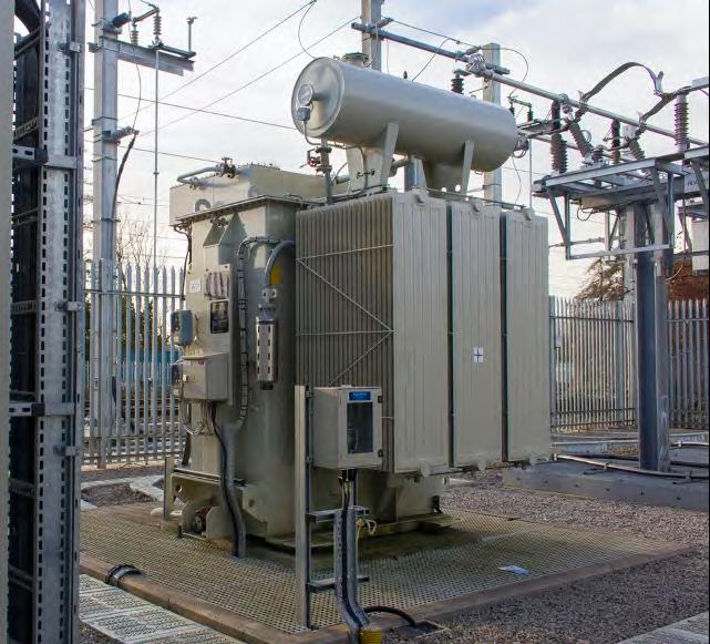
48
Figure 1: An autotransformer within a traction substation compound (photograph: Garry Keenor).
potentially locally generated supplies. Although unlikely to replace connections to the distribution networks, lineside energy storage and local generation could help reduce the peak load on the grid and reduce the need for costly power supply upgrades. Discontinuous electrification using on-board energy storage to “bridge the electrification gaps” is part of this equation but generally not suitable for freight routes.
PROTECTION AND CONTROL
Enabling new supply points and new technologies to be introduced without causing significant disruption and unnecessary costs must be an aim for the future of electrification. Using SmartGrid technology is therefore essential. There are various definitions for SmartGrid but most include the application of digital technology to monitor, control and provide network information using the latest generation of automated electrical power systems.
The railway has already developed the basic architecture for this with the IEC 61850 standard adopted on the GW main line. This gives the ability to quickly and automatically isolate faults and reconfigure autotransformer systems, thus minimising service disruption. The technology provides distance to fault analysis to accurately identify the location of faults on the overhead line reducing the time to identify and repair any damaged equipment. Using SmartGrid also enables the introduction of new technologies thus helping to futureproof the system. Although there are additional costs, the long-term advantages are significant and pressure to reduce project costs by adopting cheaper systems should be avoided.
The technology also provides the opportunity to up-skill staff, providing further benefits in a digital age. Standards need to be developed to enable procurement of “technology agnostic” systems,
not dependant on individual suppliers for ongoing maintenance and future changes, and compatible with the national Supervisory Control and Data Acquisition (SCADA) system.
BUDGETING
Traditionally, the costs of traction power supplies are included in the overall costs of an electrification project. Where each project was developed and installed in isolation this made sense. However, with the emergence of a long-term network strategy, attributing the full power supply costs to the first project in an area will result in either disproportionate costs for that project, or a sub-optimal longer-term solution that will require costly and disruptive re-work on subsequent projects as the network is joined up. Consideration therefore needs to be given to a national or regional power supply project, as in Scotland, independently budgeted from specific route projects, to ensure the optimal overall solution.

CONCLUSION
With the UK hosting the 26th UN Climate Change Conference of the Parties (COP26) in Glasgow in November 2021 and the legal requirement to bring all greenhouse gas emissions to net zero by 2050, the need to electrify the UK’s railways has again risen up the Government’s priority list. In order to meet the target, following the report from the Rail Industry Decarbonisation Taskforce, Network Rail have produced the Traction Decarbonisation Network Strategy showing 13,000 single track km of new electrification is required. To avoid repeating some of the mistakes of the past, the opportunity to approach traction power design from a whole system perspective must be grasped as part of the overall drive to make electrification cost effective and prevent unnecessarily costly PSU projects in the future.
49
Figure 2: SF6 circuit breakers (photograph: Garry Keenor).
Network Rail track renewals
AUTHOR: Chris Parker
Chris is a Chartered Civil Engineer, and a Fellow of the PWI and ICE. He has worked in the rail industry since 1972 retiring in 2004. His experience covered track and structures, design and maintenance and infrastructure management. After retiring Chris has remained active as a technical writer as well as writing reports for the PWI Journal and other organisations.
This seminar scored two “firsts” for the series, being the first to take place entirely online, and the first to employ online audience polling. The event was introduced by Network Rail’s Liam Jackson, who chaired the session. After briefing the participants and inviting them to partake in a trial poll, Liam introduced the first speaker, John Edgley, Interim Chief Technology Officer, Network Rail (NR):
PRESIDENTIAL ADDRESS
JOHN EDGLEY, PWI PRESIDENT

John commenced with well earned thanks to those responsible for the organisation and delivery of the seminar, mentioning in particular Liam, Kate Hatwell and the rest of the PWI team. Networking, John said, is a key part of the role of the PWI, and he hoped that this would become possible once again soon, when we recover from Covid-19.
The main substance of John’s address concerned his view of the principal challenges facing the rail industry, and how he sees the PWI fitting into this scenario. These challenges include:
• Recovery from Covid-19
• Asset reliability and performance
• Affordability
• Climate change and decarbonisation
John described each of these in more detail, explaining that the focus of the PWI will be:
• Supporting the Members: this is continuing despite the pandemic, using online methods. Membership numbers are increasing, and good progress is being achieved with the spread of professional registration.
• Joan Heery’s presidential themes: work on these continues, strongly supported by the 7 Vice Presidents. Corporate Membership development and the plan for young people are the two themes.
• 2020/21 presidential theme: Industry Competence is John’s theme for his presidency. He related this right back to the original aims of the Institution’s Founders. The entire industry needs to do more on professional competence, and the PWI will lead, encourage and support this. John aims to have in place a common, agreed competence framework by the end of 2021.
• Presidential themes of future Presidents: Nick Millington is to succeed John as President, and his theme will be Safety and Performance. Peter Dearman is to succeed Nick, and will take forward the theme of Electrification.
BEST PRACTICE IN CAPITAL DELIVERY PROJECTS
TONY MORGANI, ENGINEERING MANAGER STUART WITTS, SENIOR ENGINEERING MANAGER
J. MURPHY
The speakers began with an online poll, asking what people considered to be the greatest challenge they had encountered on their most recent project or task. Out of a list of about 6 possible issues, over half the audience chose “lack of clarity in requirements/ scope”. Tony began the main presentation by speaking about the Phase 2 Works at the Harbury Cutting site on the NR Oxford/ Birmingham route. These works were designed to prevent the cutting to the east of Harbury Tunnel from causing a similar problem to that which occurred in 2015 on the other side of the tunnel, when a massive landslip closed the line for about 6 weeks.
The works included stabilising the slopes over the tunnel portal by installing over 660 soil nails, regrading the lineside cutting slope, installing a contiguous pile wall along part of the cutting crest and installing berms to assist stability and aid access for future inspection and maintenance. An interesting aspect mentioned by Tony was the design and installation of the piled wall, using a reinforced concrete guide beam which was incorporated into the permanent pile cap once the piles were completed.
Stuart described the renewal of a canal bridge on the FHR5 line (Preston/Burnley/Heiden Bridge) in East Lancashire. The 100-yearold structure consisted of traditional brick abutments, supporting two tracks through wrought iron decks, each carrying one track over the canal.
As the site was effectively landlocked by surrounding features, it was necessary to use rail mounted craneage for the works. The whole design was dictated by the need to ensure that a Kirov crane could handle everything. The result was the use once more of two separate decks, but this time made from weathering steel.
It was feared that the old abutments might be unstable once the propping effect of the bridge decks was removed, particularly given the surcharge loading of the big crane behind one of them. The abutments were therefore propped by means of a substantial temporary works structure between them, installed below the original decks before their removal.
The works were enlivened, if that is an appropriate expression, by the arrival of Storm Dennis in the middle of the 9-day blockade. The high winds meant that a mobile crane in the site compound was unable to work, but fortunately it was possible to use the Kirov crane safely, and this was able to undertake the lifts that the smaller crane could not, as well as carrying out its intended duties. Delays to the works were therefore minimal.
ONLINE SEMINAR
50
TRACK AND S&C TECHNICAL STRATEGY
GARETH EVANS, PROFESSIONAL HEAD OF TRACK, NETWORK RAIL
Gareth and his team have been producing a working draft strategy and seek collaboration across the whole industry in order to refine and develop it into a document that is accepted throughout. He set out the vision for this development, covering such things as cost effectiveness, safety, reliability and resilience. Its purpose is to support collaboration across the regions and the whole industry. It should cover the whole asset lifecycle and support all the other assets/disciplines.
It has been assumed that the basics remain unchanged (for example, steel wheels and rails), that there are similar societal demands to today, and that the NR license remains.
Gareth described where this strategy fits into the bigger picture and discussed objectives and themes. He described how it has taken cognisance of the Rail Industry Technical Strategy that has been developed by the Rail Delivery Group (RDG) Technical Leadership Group and is to be issued shortly. Vision statements for 2025 and 2040 are key parts of Gareth’s draft. He discussed in more detail the objectives, themes and vision statements, as developed to date, and emphasised that a key aim is to deliver a step change in reliability, availability and whole-life costs.
Gareth ended by emphasising that the next steps involve going into listening mode, encouraging wide review of the document by others and consulting with them. He strongly encouraged people to get in touch with him and his colleagues accordingly.
SOUTH RAIL SYSTEMS ALLIANCE (SRSA) SUSTAINABLE WORKSITES
NICK MATTHEWS, PROJECT ENGINEERING MANAGER, SRSA
Nick gave an inspiring presentation about the work that is going on within the SRSA to decarbonise worksites. Traditionally, worksites have depended heavily upon carbon based fuels, principally diesel or petrol. These are used to generate electricity and also to power tools. This creates noise and pollution and is unsustainable. In addition, maintenance of powered plant and generators is costly and the process of refueling is potentially hazardous and costs time, resources and money.
Internal combustion engines (ICEs) needed to be eliminated. However, there were apparent reasons not to do this. The weather/ climate of the UK, the size and cost of the alternative equipment, and the fact that solar panels cannot work in the dark or under cloud cover, these all looked like serious obstacles to change.
There is a solution: solar harvesting. This means the employment of power storage that gathers in solar power whenever it’s available,
MANCHESTER METRO CITY CENTRE RE-RAILING
JENNIFER MCKINNEY, HEAD OF INFRASTRUCTURE NICK COLES, CAPITAL WORKS DELIVERY MANAGER
MANCHESTER METRO
Jennifer started the presentation with an overview of Manchester Metrolink, which she said is the largest UK light rail network. It is operated and maintained by joint venture KAM (Keolis Amey Metrolink), with Transport for Greater Manchester (TfGM) responsible for renewals, enhancements and extensions. Keolis is also a member of other joint ventures, and in the UK help to run the Docklands Light Railway and the Wales & Borders Railway.
The challenging project involved rectification of rail damage and wear on the Market Street curve in the centre of Manchester. KAM was managing the defective rails by means of a 5mph temporary speed restriction and a temporary approved non-compliance. Measures required to manage this involved a special testing and monitoring regime. Unfortunately, this could not continue indefinitely, and it was eventually going to lead to line closure unless the rails were changed. This was problematic, since there are few experienced suppliers capable of carrying out the works. These were all heavily engaged on works on other UK metros at the time. Whilst “DIY” is not a normal activity for KAM, this time it was decided that it was the only viable way out of the problem.
and releases it when the demand arises. Typically this means arrays of solar panels feeding into battery banks. When the power is to be used, inverters convert the stored energy to the appropriate form (Voltage, AC or DC, as required) and deliver it to the users.
Nick showed a video that featured a site at Gloucester in 2019, where an S&C renewal site was powered in this fashion. Together with energy saving measures like heavily insulated site cabins with PIR control of internal lighting, energy efficient appliances and electrically powered tools, major changes were made. Consequently, the consumption of diesel on the site was reduced by 98% with a cost saving estimated at £210,000 and a cut in carbon dioxide emissions of some ½ million kg.
Other issues were addressed as well, for example, the use of singleuse plastics, which was significantly reduced. Similar approaches are now being used consistently by SRSA, incorporating lessons learned in order to continuously improve. Work continues with tool and plant suppliers to find and improve electric and battery plant and tools. A solar powered CCTV system (Gate Guardian) has been developed and work is under way on solar powered depots, RRVs that don’t use fossil fuels, and more.
KAM engaged with Pod-Trak, a company with relevant experience from the Birmingham tram system, to carry out the work together. Jennifer continued to describe the challenging timescales, the measures taken to allow continued Metro operation via alternative routes and the management of customers and city centre visitors. Service alterations, bus substitutions and customer liaison and control were all employed. The management of relations with key stakeholders like the Mayor, Council, local businesses and more was an essential element.
Nick gave more details about the practical aspects, such as worksite mobilisation, security and signage. A major issue was the block paving of the Square, significant areas of which needed to be lifted to give access to the track. He likened this to a large and weighty jigsaw and said that a key lesson learned was that the blocks should have been surveyed before they were moved, and marked so as to identify them for correct repositioning after the track works were completed. He reemphasised Jennifer’s point about the crucial importance of good liaison with stakeholders. Another serious influence was the weather, which threw everything it had at the team during the site works.
Despite all the challenges, the works were successfully completed in the eleven days that were eventually allowed for the job after the agreement of a two-day extension to the original plan. Many lessons were learned besides the one about paving. These included the need for remote condition monitoring of the infrastructure and automated measurement of rail wear and degradation.
2020-2040
51
PROJECT HEINEKEN & KILSBY TUNNEL
AMEET
MASANIA, HEAD
OF INNOVATION
JAMES HARVEY, OPERATIONS DIRECTOR
CENTRAL RAIL SYSTEMS ALLIANCE (CRSA)
Ameet began by describing Project Heineken. This is a mapping tool that allows the visualisation of all the works needing to be undertaken in a given geographical area, in order to maximise the efficient use of track access. The background to its development is the devolution of track renewals works to the Regions/Routes in Network Rail, sitting alongside signalling, maintenance, civils, enhancement and works delivery. It uses a wide range of data sources. Ameet showed a video presentation that depicted how it works and what data sits within it. Following that, he described a trial application at North Wembley. The results of that, he said included the successful completion of twelve additional tasks that would not have been closed out under normal processes, and consequent great feedback from stakeholders.
SYSTEM APPROACH TO ELECTRICAL CLEARANCES AT OVERLINE STRUCTURES
James next presented about Kilsby Tunnel, describing how at only three weeks’ notice, stakeholders had agreed that NR could have a blockade of the tunnel to carry out work to remove condition of track speed restrictions within it. This was made possible by the reduction in train services that had come about from the Covid-19 pandemic, which made it practicable to divert traffic for the duration. The line was closed from 2-17 May 2020.
Network Rail and the CRSA were challenged to maximise the use of this unexpected track access, which affected a significant length of route either side of the tunnel, as well as that structure itself.
The blockade was finalised at very short notice, leaving only two weeks to plan the works to be carried out. Nevertheless, a huge quantity of work was successfully undertaken by multiple teams. James described how this was organised to safely make the best of a blockade that might have cost £25 million under normal circumstances.
TOM
KEMP, PRINCIPAL PROJECT ENGINEER (PPE) (E&P) ANDREW JARMAN, PPE (B&C) DAVID WOODS, PPE (TRACK)
NETWORK RAIL
Aspects of the Trans-Pennine Route Enhancement project and Bolton/Wigan Electrification project were discussed to examine the issues around electrical clearances for electrification. Tom began by explaining that the key objective is to deliver cost-effective electrification. Andrew Haines, he said, has endorsed the necessity of electrification in order to meet essential carbon reduction targets. Tom spoke of the process used to obtain the endorsement of the Route Asset Managers (RAMs) of all three disciplines for proposed methods and designs, in order to ensure that all are happy with the solutions selected. The industry has a traction decarbonisation strategy that requires the electrification of 11,700 single track
HATFIELD 20 YEARS ON
BRIAN WHITNEY, ENGINEERING EXPERT, TRACK AND STRUCTURES, NETWORK RAIL
Brian began with a brief resume of the sad events of 17 October 2000, when the 12.10 departure from Kings Cross derailed on the Welham Curve about 16 miles north of Kings Cross, at 115 mph. In the resulting crash four people were tragically killed and 30 were hospitalised. The cause of this crash was the failure of the high rail of the curve, which shattered into some 300 pieces over a significant length. This failure was found to have resulted from rolling contact fatigue (RCF) damage, which took the form of what was then known as gauge corner cracking (GCC).
The crash led not only to an inquiry into the incident itself, but also very significant emergency precautions across the UK rail network, a massive amount of research and investigation into RCF, wheel/rail interaction and related matters, major changes in the management of rails and much more. It led to the demise of Railtrack and the creation of Network Rail.
Brian described the key points that were the results of the formal incident inquiry. These included: the failure to properly appreciate the risks of RCF/GCC, the failure of the local inspection regime, the failure to take proper actions to maintain and ensure the safety of the line, the failure to complete the urgent proposal for the re-railing of the curve and a failure to act upon audit reports.
kilometres (stk) out of the 15,400 stk that are currently not electrified. A crucial tool in cost effectively meeting this objective will be the concept of Voltage Controlled Clearances (VCC), as developed for application at the intersection bridge at Cardiff. Tom then talked about how NR has developed an agreed process for applying the optimal solutions to each and every affected structure on a route to be electrified. A wide range of stakeholders were involved in and agreed to this development, which has resulted in the creation and application of a “one page” document for the review of the options for a structure and agreement to the selected approach.
David and Andy each gave their overview of this procedure from the perspectives of their respective disciplines, before Tom discussed the process in more detail and showed examples from the TransPennine Upgrade project. He told how the VCC concept could obviate the need for structural interventions at all four tunnels and 22 of the bridges on the affected routes. David described similarly how the Bolton/Wigan Electrification is also significantly benefitting from this. He emphasised that whole-lifecycle assessment is being applied, not just short-term project costing.
Brian then considered what has been done since. Firstly, there was a massive change in the management of rails. From the early 1960s until 2000 there was a consistent figure of about 1000 rail breaks per year on the NR network. Within a very short timescale after Hatfield, this was reduced to about 100 per year. A significant element of this was initially achieved by a huge re-railing programme.
Re-railing was not the sole contributor however, and would alone not have caused a sustained reduction in the rail failure rate. Brian described the other actions that have continued to suppress the failure rates since the early post-Hatfield years. These include inspection and maintenance improvements that have enabled the suppression and control of rail defects, such as RCF defects like squats and GCC.
He was insistent that we cannot rest on our laurels or take this past success for granted. A sobering view he presented was that of the history of train accidents on the same curve at Hatfield. Since 1850, there have been 22, including three rail break incidents that derailed passenger trains.
We must look at whether the controls introduced in the last 20 years are still effective. We must look out for new phenomena and be prepared to learn new lessons. “50 by 30” is Brian’s mantra it is not good enough to rest at 100 rail breaks a year. A long continuous improvement plan is being implemented, based upon monitoring, data driven analysis and the understanding of root causes.
52


The Railvac and Ballast Feeder System industry concept delivers increased re-ballasting capacity. Always non-intrusive, with the track in situ and without disconnections! www.railcare.co.uk Most Innovative Small Plant 2017 Awarded to Cembre for EcoDrill all weather battery rail drill Most Innovative Small Plant 2019 Awarded to Cembre for battery powered sleeper drill Most Innovative Small Plant 2014 Awarded to Cembre for Robokatta automatic rail disc saw Impact on the operator: • Vibration: Zero • Physical Effort: Zero • Harmful Dust: Zero • Sparks: Zero • Exhaust Fumes: Zero • Acoustic Noise: Minimum Work area LED lighting Battery sleeper drilling machine SD-19BR2-RPE with CS-EU support trolley Rotation sense/error signaling lights ROBOKATTA BATTERY DRILL FOR WOODEN SLEEPERS SD-19BR2-RPE Design, manufacture and sales of elec trical connectors and associated tools, cable accessories, marking systems, toolings and products for railway ap plications. Tools for pressed joints for water, gas, steam, waste and HVAC and related accessories. In house repair, re furbishment and calibration of toolings. 53
ANDY2
Any railway project carries an enormous amount of risk, and as an industry we are incredibly risk averse. Delivery Managers often put expensive contingencies in place to ensure successful delivery of the project. These same Delivery Managers, whilst aware of the small steps needed to make the process more resilient, concentrate on the largest elements such as spare plant to cover potential breakdowns, extra manpower and building excess time into possessions to reduce risks and deliver their projects successfully.
However, at any part in the delivery process, small failures can lead to big consequences. This is best summed up by the old proverbial nursery rhyme, “For the want of a nail”:
For want of a nail the shoe was lost.
For want of a shoe the horse was lost.
For want of a horse the rider was lost. For want of a rider the message was lost.
For want of a message the battle was lost.
For want of a battle the kingdom was lost. And all for the want of a horseshoe nail.
Recently I was talking to a young engineer who commented that he often calculated the rail temperature on his stressing shifts by making an adjustment to the air temperature recorded on the dashboard of his van. Stressing in this manner obviously invalidates the shift, but before condemning this young engineer, remember that his colleagues must have endorsed this method and condoned this shortcut. This behaviour demonstrates that there is a cultural problem in his depot, but after discussions that I have had with others, it has transpired that rail thermometers are actually a scarce resource across many different companies within our industry. Why do you think this is? Is it the cost to the parent companies? Is it the failure of the process that ensures the sharing and distribution of thermometers to all that need them? Or a combination of both? And what of the managers who are responsible for auditing and ensuring this process is compliant with current regulation and standards? In short, the lack of a thermometer highlights a complete system failure.
Whichever the cause, a quick internet search tells me that a magnetic rail thermometer costs £66. So, when you think about the cost of a failed shift, a track gang to clip and unclip, a team of welders and a competent technician - and then factor in all of the material costs for a restressing shift such as the closure rails, welding portion, the new clips, pads and insulators, then for the “want of nail” is particularly pertinent.
Andy Steele Technical Content Manager Permanent Way Institution andy.steele@thepwi.org

like to present at one of our seminars. We’d be delighted to hear from you! Also, if there are particular subjects you want covered in the Journal or at a seminar, please let us know.
Resilience - how we plan, adapt and respond to seen and unforeseen change is a broad theme of this Journal edition. I have been thinking about what resilience means in terms of how individuals and teams work to play their part in delivering a consistently safe and well performing railway. Railway performance, in the overall sense, is deeply affected by the way people work and their ability to be resilient. Our resilience can have a deep impact on personal wellbeing and that of the folks we work and live with. So, what can be done to help our resilience at work? I’m going to focus briefly on three of the many factors in play that affect this:
How resources and particularly people are organised and used. As an example, organisations often find themselves relying on key individuals, whose knowledge and skills are unique and who become “single point failures”. If for whatever reason, they are unavailable, progress can grind to a halt. Typically, these folks have huge pressure piled upon them, which they usually work hard to cope with and deliver. Although, it may unwittingly give these people a sort of “hero” status, it comes at a cost to their overall wellbeing, as well as to the efficiency of the organisation. It can be very hard to get out of this position because passing on their knowledge to others takes more of their time and further increases the pressure on them. It is important to try and remove single point failures by having robust plans to train up others, to put in place succession planning, to “de-skill” activities by capturing knowledge in systems and by taking away the more trivial activities of a really skilled person and giving them to others. The availability of physical resources eg plant and machinery may also cause issues and plans to increase these through long term planning or responsively by having contracts in place to quickly hire in extra resource or by coordinating plans across projects and maybe companies as well.
Having resilient systems processes. It may not sound glamorous but having a good quality system in place is really important for resilience. Maintaining simple, easy to comply with, well briefed processes and quality instructions help with adapting to changes. They cut down mistakes, iron out waste and increase efficiency. You know if you have a good set of processes and instructions in place if people are working to them and not around them to get things done. If they are not, change the quality instructions! Building good processes into well integrated IT systems that are “locked down” and relying on a “single source of the truth” for their data is also a must. You will know how good they are by the extent to which people feel the need to set up their own little spreadsheet workarounds! Everyone should be encouraged to have a mindset of improving the official systems and processes rather than inventing new ones under the radar. Easy for me to say, very difficult to achieve!
Making plans for when things go wrong. Ideally this should flow from having in place high level company crisis plans. For example, what would we do if the building burns down? A key asset breaks or is stolen? Or our site or offices flood? How would we make sure individual projects have thought out “Plan B” options for if “Plan A” falls apart? I believe that this year our ability to plan for future crises and to have alternative options thought out will have been much improved by the strategies and actions that were developed to respond to the global pandemic.
I have only scratched the surface of this subject, though hopefully I have given some food for thought about resilience and how we can improve it in the way we work.
Andy Packham Technical Content Manager Permanent Way Institution andy.packham@thepwi.org
54
PWI Technical Content Manager’s (TCM) Andy Steele (left) and Andy Packham (right) source interesting high-quality technical papers and content for the PWI Journals, textbooks and other printed and online media. They also arrange PWI seminars and training courses, packing them with relevant technical content, delivered by presenters who have great knowledge and a passion to share it. Get in touch with us if you have a potential Journal paper to contribute or if you would


¬ tolerates vertical track position changes ¬ no bearing on the sleeper surface ¬ installation is possible without any machinery ¬ in combination with the 1,200 mm STRAIL inner panels > increased position stability and suitable for maximum loads ¬ pontiSTRAIL 713 and STRAIL outer panels use the same kerbstone > easy exchange for higher loads STRAIL (UK) Ltd. - Richard Whatley Tannery Lane // Send / Woking // GU23 7EF // Great Britain // Phone +44 (14 83) 22 20 90 // Fax + 44 (14 83) 22 20 95 // richard@srsrailuk.co.uk THE EXTRA STRONG SYSTEM FOR MAXIMUM LOADS pontiSTRAIL - aluminum bearer and rubber panel, a combination for highest demands. series of books first published over 35 years ago. It is the definitive guide to rail-mounted and selfpropelled equipment specifically used for working on, or assisting in, the maintenance and renewal of the railway infrastructure in Great Britain. It is a hardback, full colour, thread-sewn publication with extensive colour illustrations. Included within it are comprehensive details of: ■ On-track machines. ■ Road/rail vehicles. ■ Small plant. ■ Owner listings. ■ Manufacturer details. On-Track Plant - 11th Edition can be obtained from Book Law Publications. Copies cost £40.00 each - plus postage and packing. To obtain your copy, with secure online ordering, please visit the website: www.booklaw.co.uk Alternatively, orders can be placed by telephone on: 0115 961 1066 Or by post from: Book Law Publications, 382 Carlton Hill, Carlton, Nottingham, NG4 1JA.
of On-Track Plant - 11th Edition OTP11 half page advert_OTP11 half page advert 18/05/2020 13:03 Page 1 55
Publishers
Great things are coming

…and now they’re here! The new PWI website is live online and we cannot contain our excitement! The central team spent the last few months of 2020 beavering away alongside website partners All My Systems, and this new and improved digital home is now ready for you to explore.

You will find all the usual important stuff about your Membership, plus information on events, training, professional registration and more only now on a fresh and easy-to-use website powered by a far greater user interface and content management system. Log into your Member’s portal to track your Continued Professional Development, benefit from discounts, and book your place on training courses and events. Plus, access hundreds of technical resources in our new Knowledge Hub, which you can read more about on page 74.


We hope you enjoy the new look and feel, which is aligned to our 2021 brand enhancement, and that all these changes show our continued commitment to providing the best services and experiences to our valued community.

FIND OUT HOW TO GAIN A PROFESSIONAL TITLE
TRACK YOUR PROFESSIONAL DEVELOPMENT SIGN UP FOR TECHNICAL TRAINING
... 56
LIVE NEW WEBSITE

57


SLIDING FRICTION BUFFER STOPS SKELTON Rawie Friction Buffer Stops provide protection for track ends worldwide. They can be designed to suit all types of rolling stock, accommodating varied train weights and speeds. Manufactured by A.RAWIE GmbH & Co. KG. Tel: 0049 541 91 2070 bufferstops@rawie.de www.rawie.de Supplied in UK & Eire by H.J. Skelton & Co. Ltd. Tel: 0044 1635 866877 sales@hjskelton.com www.hjskelton.co.uk #thepwi thepwi.org PermanentWayInstitution @PermWayInstit Permanent Way Institution @the_pwi RECEIVE 4 ISSUES OF THE PWI JOURNAL ANNUALLY (£15.00 PER ISSUE FOR NON MEMBERS) PWI ANNUAL MEMBERSHIP £86 Journey with us 58
Thermit Welding is part of the Goldschmidt Group –the unique, global network of experts for the railways. Together we lead your rail infrastructure into the future – with smart solutions, services and products.


www.goldschmidt.com


59
WE ARE GOLDSCHMIDT
PROFESSIONAL REGISTRATION


Professional Registration is an important step in pursuing a career in engineering and it lends itself to a ready-made career path, progressing through the grades as your experience broadens and deepens.

Putting those letters after your name (EngTech, IEng or CEng) instantly tells employers, clients and wider society that your competence and understanding of engineering principles has been independently assessed, that you have the knowledge, skills and professional attitude they value, and that you are committed to developing and enhancing your competence. It sets you apart from your non-registered colleagues.
The right professional registration title for you is based on your academic and professional competence: here’s a general guide…
Engineering Technicians apply proven techniques and procedures to the solution of practical engineering problems.
They hold Level 3 engineering/technology qualifications AND 2-3 years industry experience, OR 3-5 years industry experience.
Incorporated Engineers maintain and manage applications of current and developing technology, and may undertake engineering design, development, manufacture, construction and operation.
They hold Level 6 (Bachelors) engineering/technology qualifications AND 3-5 years industry experience, OR 5-10 years industry experience.
Chartered Engineers develop solutions to complex engineering problems using new or existing technologies, and through innovation, creativity and technical analysis.
They hold Level 7 (Masters) engineering/technology qualifications AND 3-6 years industry experience, OR 10-15 years industry experience.
THE WEBSITE FOR INFORMATION AND SUPPORT
HEAD OVER TO
60
I currently work as an Inspector of Railways Track Engineer at the ORR and a key part of my role is to lead our technical liaison with industry to secure and maintain safe management of the track asset. As a result I liaise with track personnel of all levels across the rail industry, from the heritage sector to the Channel Tunnel. I applied for joint Chartered status with the PWI to demonstrate professional recognition of my experience working on the track asset, with a hope this will aid in conversations required in my role going forwards.
The application was a clear and simple process. The application form required demonstration of relevant permanent way experience, and demonstration of a commitment to continuous improvement of staff and system safety. Clear guidance is provided on possible examples that could be used to meet this requirement. Following submission of your application you will hear back within six weeks, and the Reviewers can either recommend that you be elected as a Chartered Engineer with the PWI, or they may want some further information from you first, or they may invite you to a Professional Review Interview.
The PWI is held with very high regard in the industry and having professional recognition from the Institution provides an immediate demonstration of my experience in rail infrastructure, which I hope will benefit my liaison across the industry going forward.
 Gregory Strong CEng MIMechE MPWI Inspector of Railways Track Engineer ORR (Office of Rail and Road)
Take forward the shared learnings, so you can model good practice when you Plan, Do and Reflect on your development.
FIND THE REPORT ON THE WEBSITE
I am pleased to tell you that we now have over 200 registered engineers, with another 350 in the wings including 20 candidates approved for the Experiential Learning route to Chartership.
Last September’s virtual PWI Professional Review interviews were a great success and involved 14 PWI Reviewers undertaking Chartered and Incorporated professional reviews, and technical report interviews. There was a good pass rate which is a great tribute to our mentors and sponsors. As Technical Director, I undertook two audits of these events.
Following attendance by Dr Matthew Frost (Academic Panel Chair) and myself at an Engineering Council workshop on Individual Routes, we are looking at enhancing the PWI routes going forward to assist people with HNC and substantial experience to move towards IEng with experiential learning or an appropriate technical report route. I am also working in conjunction with Network Rail to blend their Track Maintenance Engineers courses with the academic competence requirements for IEng.
Our Professional Registration Development Officers are working well to promote industry links through more workshops offered to Corporate Members. Finally, we have completed our second round of annual CPD audits following the requirement to check members are up to date.
And remember, reading this Journal classifies as CPD activity!
Brian Counter TECHNICAL DIRECTOR Permanent Way Institution technicaldirector@thepwi.org

The PWI is here for your journey and would love to support you in your career aspirations.
www.thepwi.org profeng@thepwi.org
Professional registration is open to any competent practising engineer or technician.
Different levels and pathways to registration are available, depending on your experience, training and qualifications.
FIND YOUR ROUTE TO REGISTRATION ON THE WEBSITE
WWW.THEPWI.ORG
PROFESSIONAL REGISTRATION WITH THE PWI IS SUPPORTED BY NETWORK RAIL AND TRANSPORT FOR LONDON

CPD AUDIT 2020 – WHAT WAS DISCOVERED?
61
IN-PERSON OR VIRTUAL TECHNICAL TRAINING TO SUIT YOU

COURSES
DELIVERED BY INDUSTRY EXPERTS
PWI training started over 100 years ago and has been providing high level technical training for engineers and professionals operating at all levels ever since.
Our courses are designed to develop skills and knowledge in all aspects of track repairs, renewals and projects and can help you on your journey to professional registration.
Whether in person or online through our virtual classroom, access first class technical training, developed and delivered by experienced rail infrastructure experts. Virtual candidates can enjoy the four-day course with breaks just like the in person equivalent, only without the travel and hotels!
All PWI courses use the most up to date content and standards; both attendance options provide the same high quality materials, tutorials, group discussions, interactive working examples and access to tutors in a 1-to-1 environment to answer queries or recap areas of uncertainty.
A printed course book, personal workbook and PWI textbooks will be made available in class, or posted to your home address ahead of your start date for virtual candidates.
Awards are made by the PWI upon successful completion of written or online assessments. These comprise Certificates and a Diploma, which has been professionally validated at university level.
Join us in person or in our virtual classroom from your home or office as we deliver our industry revered, first class training directly to you.
I enjoyed the interactive discussions and learning with face to face group discussions. This has given me a greater understanding of the challenges involved.
Track Delivery Manager Transport for London
This is good quality training given by very knowledgeable instructors with some interesting topics of debate covered and discussed face to face by a range of experiences. Also this has enabled me to gain a better understanding of the railway as a system, not just my discipline.
Design Engineer Amey
I enjoyed learning about the different sections of the rail industry in areas I am unfamiliar with such as track maintenance.
Engineer AECOM
62
Part A: 23 25 February 2021 / Part B: 9 11 March 2021
Part A: 28 30 September 2021 / Part B: 19 21 October 2021
Delegates on this two-part course will gain comprehensive detailed knowledge of S&C and how to undertake refurbishment safely, efficiently and to the required engineering quality. The course will cover both the track assemblies and the trackbed under S&C.
Participants will undertake detailed analysis and inspection of layouts so that they can scope and specify work correctly to provide the necessary life extension of the layout. The course will then ensure that delegates understand the various maintenance interventions suitable for S&C and its components and can plan those required in the correct sequence. Modules include: S&C Components Design and Analysis / Site Survey and Measurement / Scoping and Planning.
Delegates will have to pass a formal assessment at the end of the course and will be awarded a PWI Certificate in S&C Refurbishment on successful completion.

Course cost: £895 Accommodation cost: £325
See www.thepwi.org for full details
PWI TRACK ENGINEERING DIPLOMA

The aim of the programme is to give delegates an understanding of the principles, theory and practice of track engineering in the UK. It is comprised of three modules and involves 100 hours of taught study all mapped to HE Level 6. Upon successful completion of all three modular assessments, candidates will be awarded the PWI Diploma in Track Engineering.
This course is aimed both at newly qualified and experienced engineers, and will give delegates the knowledge and skills needed for professionals in track engineering.

MODULE
1: TRACK MAINTENANCE
18 21 January 2021 Virtual Training Classroom 19 22 April 2021 Virtual Training Classroom 7 10 June 2021 Derby 6 9 September 2021 Virtual Training Classroom
Gives a basic understanding of track engineering and its theory and context. Develops a knowledge of track types and features, its interfaces with other rail infrastructure including earthworks, structures and clearances, and track maintenance including ballast, drainage, stressing, grinding and welding.
When I planned the 2020 schedule, little did I know that we would be doing so much, if any, virtual on-line training in track. We had thought about it following requests from Australia and India but kept it in the “difficult” box.
As we start 2021, it is good to reflect upon last year. We actually did 15 week-long courses, four at Derby and eleven online with over 260 trainees. We awarded 50 Track Engineering Diplomas and 24 certificates in Switch and Crossing Refurbishment. It was a great pleasure to me to be able to rescue our courses, particularly for our regular Network Rail Graduates who seemed very pleased to be able to have a chance to learn and have fun with our characterful bunch of trainers. The great news is that we will start on electrification training soon and have ambitions to create a PWI Electrification Engineering Diploma.
We have confirmed plans for 20 courses in 2021 with our continued offering of eight virtual courses and twelve face to face sessions at Derby, Glasgow, Surrey and Coventry.
The S&C Refurbishment courses are taking off and we see these as a great way that the PWI can pass on knowledge in this critical area where we can help to upskill our engineers. We have plans for more technical training, and areas under consideration are surveying, gauging, track geometry, level crossings and track handback - more ideas welcome!
Counter Technical Director Permanent Way Institution technicaldirector@thepwi.org
MODULE
2: TRACK
DESIGN 1 4 March 2021
WWW.THEPWI.ORG
PWI S&C REFURBISHMENT TRAINING COURSE
21 24
20 23
25 28
Classroom
upon
design for projects and enhancements. Through design case studies and exercises, develop skills in track design of plain line and switches and crossings, component
and configurations,
innovations and life extension, route evaluation and
ADVANCED
8 11 February 2021 Virtual Training Classroom 17 20
2021
19 22 July 2021
8 11
6 9
study becomes more strategic and delivery oriented with advanced asset management techniques and applications. Gain a deep understanding of UK track renewal planning, plain line, S&C, existing and future methods, rail renewal scenarios and optioneering, and learning from accidents. Understand advanced technical rail management issues, rail sustainability and strategic track asset management. Module cost: £645 (Virtual or Derby) Accommodation cost: £245 See www.thepwi.org for full details Top-up qualification to IEng for HND / Foundation Degree Holders We are monitoring our plans to deliver our training courses and are working very hard to ensure learning with us is not interrupted. We are committed to delivering first class technical training, developed and delivered by experienced rail infrastructure engineers. Please check the website for the most up to date information or contact us: secretary@thepwi.org 01277 230031 (option 1) COVID-19
Derby
June 2021 Virtual Training Classroom
September 2021 Derby
October 2021 Virtual Training
Focuses
track
knowledge
layouts,
trackbed design. MODULE 3:
TRACK ASSET ENGINEERING AND RENEWALS
May
Derby
Virtual Training Classroom
November 2021 Derby
December 2021 Virtual Training Classroom The
Brian
In-person courses held at the Derby Conference Centre in Derby. These courses include all training materials and lunch. Accommodation at the venue includes evening meal, single room and breakfast.
All prices are exclusive of VAT. FOR FURTHER INFORMATION AND BOOKING VISIT THE WEBSITE
63
secretary@thepwi.org 01277 230031 option 1 technicaldirector@thepwi.org
Despite the recent falls in passenger traffic consequent on Covid-19, over the longer term the climate change and decarbonisation agendas remain set to drive growing volumes of freight and passenger traffic onto rail networks. As the demand for rail transport bounces back and as train services are added to the network to meet growing demand, access to carry out maintenance, renewal, and project work will remain at a premium.

The pressure to do more work in shorter possessions drives a requirement for more productive, mechanised, work delivery methods. Effective, safe, and highly productive plant is an essential component of


this. Plant and the methods and strategies to deploy it that can together deliver high quality, durable infrastructure at lower unit costs is crucial to meeting industry challenges: along the way it must play its part in reducing rail sector carbon emissions and other environmental impacts, and in improving the performance and reputation of the railway.
This seminar will provide delegates and speakers with an opportunity to understand and debate the requirements for plant to meet these challenges, and the solutions that are being deployed and developed to deliver them.

PWI TECHNICAL SEMINAR PLANT AND MACHINERY to support rail infrastructure renewal and maintenance for the 2020s and beyond 26 MAY 2021 SWINDON STEAM MUSEUM BOOKING NOW OPEN: www.thepwi.org £85 MEMBER £150 NON-MEMBER Sponsored by SPONSORSHIP AND EXHIBITOR SPACE AVAILABLE Contact 01277 230 031 / secretary@thepwi.org 64
Plasser UK, the agents for Plasser & Theurer and ROBEL, have been established in the UK since 1960. From our workshop at West Ealing, we facilitate the sale of new Plasser & Theurer and ROBEL on-track machines and ROBEL hand-guided tools, provide training and sell spare parts from our well-stocked warehouse and maintain, repair, overhaul, and upgrade older machines ensuring decades long reliable service life from these high-quality machines.
In the past 5 years we have successfully introduced the latest generation 09-4x4/4S dynamic continuous action tamping machine with dynamic track stabilisation, 08-4x4/4S
cyclic action tamping machine and GWS-75 in possession switch tamping machine; the ROBEL Crossrail Engineering train, the High Output Ballast Cleaning System 5 including RM900 + 09-CM ballast cleaner with integrated continuous action 2-sleeper tamping and stabilising, 09-3X 3 sleeper continuous action tamping and stabilising machine, the USP5000 and USP6000 ballast regulating machines and the revolutionary ROBEL Mobile Maintenance Trains (MMT)
The Plasser & Theurer and ROBEL portfolio of machines cover all aspects of rail bound installation and maintenance. The new plant
includes the URM700 S&C ballast machine, new generation TRM’s and TRAMM’s as well as fully automated Long Welded Rail delivery and recovery trains, plus the FUM OHLE installation and maintenance machine. This machine installs the wires under very precise constant mechanical tension ensuring that once installed on the night no return shift is required to re-register as the wires remain in their final installed position.
Plasser UK and Plasser & Theurer are proud supporters of the PWI.

Swietelsky Babcock Rail was established in 2004. Our highly successful Joint Venture partnership now has the most capable and diversified fleet of on-track machines in the country and has built a strong reputation for innovation and for introducing first of type equipment.
We were the first in the UK to introduce the Unimat 09-4X4/4S Dynamic Tamper with integrated DTS in 2014, which is the latest generation continuous action S&C machine. By June 2021 SB Rail will be the largest operator of this type, with 6 machines operating across the
UK taking our UK fleet size up to 27 machines. Some of our firsts include undertaking tandem tamping of S&C, 125mph hand-back after both plain line and S&C renewals and the first to introduce technologies such as Sprinter tamping, Curve Laser and Tandem Drive and the first to achieve a 100% track quality measure. Our entire fleet utilises 100% biodegradable oils thus reducing our impact on the environment.
Not only do we own and operate tampers and regulators we also own and operate four Kirow Multitasker 250 Rail Cranes across the UK
which utilises our unique robot-arm technology which combines precision, speed of operation and the safest working methods.
Since 2014 we have invested over £35 million in cutting edge machinery to service the UK rail network covering geographical areas from the North London stations up to the North coast of Scotland.
As one of the first Corporate Members of the PWI we are proud to sponsor the Plant & Machinery seminar.
VolkerRail is one of the UK’s leading multidisciplinary railway infrastructure contractors, with a successful track record of delivering projects for a range of clients including Network Rail Transport for London and UK light rail operators. Our offering is diverse ranging from small contracts to joint venture and alliance projects in excess of £1bn.

Our detailed understanding of the industry comes from years of experience on heavy and light rail networks, and our skills range covers every aspect of track renewals, maintenance
and construction, HV and LV power, signalling and electrification. This includes complete design and build capability, which can be delivered individually or as part of a fully integrated project; all of which are enhanced by our in house plant division.
Volkerrail is a market leader in rail plant supply, and one of the few contractors with a railway safety case to operate plant on the mainline railway. Our fleet includes: plain line and S & C tampers, ballast regulators, Kirow rail mounted cranes and a variety of On Track Plant including

beaver lightweight tampers, MEWP’s, 3600 excavator cranes, as well as an array of rail mounted support vehicles and an extensive range of small plant and equipment.
The reliability of our fleet is class leading as evidenced by client league tables, we employ a maintainer/operator system with highly trained personnel who are considered some of the best in the country. Our specialist plant team provide a fully integrated planning service including lift operations and route planning, route planning.
65
NEW MEMBERS
We’re honoured to have you on board and are thoroughly looking forward to working with you. We’ll keep you updated on news and events via our monthly newsletter as we don’t want you to miss a thing. We have a thriving social media network and we’d love to see you get involved! We’re here to help, so if you have any questions, then shout out!
ASHFORD: Callum Lawson, Joshua Hurley, Luke Clark, Cathan Bezuidenhout Jones, Daniel Fosdike, Tom Pattinson. BIRMINGHAM: Natan Read, Nagham Johnson, Flynn Cremin, Jordan Miotk, Luke Seabright, Daniel Filograsso, Monika Cain, Muhammad Musaddaq Saeed, Daniel Thomson, Justin Lewis, Jovell Corbett, Abdul Nasser Salidu, Kevin Koranteng, Jordan Smart, Joshua Pitters, Zubairi Sentongo. CHESHIRE & NORTH WALES: Callum Thomson. CROYDON & BRIGHTON: Alex Ekers, Ryan Palmer, Mohammed Hamzah Tahir. EDINBURGH: Daniel Mullen, Ross Goodall, Drew MacDiarmid, Douglas Cringles, Rorie Watson, Scott Ritchie, Ben McGarrity, Paul Chambers, Jamie Orme, Wayde Pasifull. EXETER: Scott Glover, Stephen Walthew, Laura Johnson, Paul Harrison. GLASGOW: Patrick Marshall, Nicola Melling, Gena Merritt, Steven Ho, Jonathan Macmillan, Liban Ibrahim Abdi, Fraser Martin, Paul Moran, Oscar Smith, John MacArthur, Jack McComish, Emma Dunne, Ross Meikle. INTERNATIONAL: Nicole Chan, Stephen Day, Babulal Sahu, Ujwal Bakarapu. IRISH: Shane Dolan, Shane Ryan, Nick Kelly. LANCASTER, BARROW & CARLISLE: Liam Powley-Campbell, Alex Thistlethwaite. LONDON: Jon Winborne, Simon Bretherton, William Chowns, Pak To Kam, Mark George, Dilraj Gakhal, Nikki Haslett, Phil De’Ath, Declan Burke, Maurice Sylvester, Michael Ainslie, Kevin Syc, Kenneth Lambert, Marley Kelley, Sammy Kibye, Lewis Brown, Mahdi Chentouf, Michael Cowan, Andrew Jones, Khaled Ellithy, Adam Ersser, Amir Siddiqui, Constantine Collias, Joyce Bassengue, Jemall Curtis-South, Hassan Sameem, Robyn McKenzie, Ali Salim, Paul Jessett, Ethan Kyiet, Andrew Junior Bangura, Jonathan Davidson, Oliver Stewart, Brian Garnham, Ashley Rust Williams, John Lambert. MANCHESTER & LIVERPOOL: Cameron Marron, James Marshall, Dona Valentinova Petrova, Genaro Yambao, Patrick Timoney, Bryn Webb, Kaylan Jackson McCabe, Sohaib Shahid, Mark Shead, David Robb, Pete Sommers, Daniel Hopkins, Kevin Brown, Jack Mills, Adam Henry, Lewis Jones, Fahima Rashid. MILTON KEYNES: Thomas Bishop, Muhammad Ahsan Faraz, Andrew Starr, Masoumeh Rahimi, Damiano Acerbi, Ellis Rust, Wei Khang Lim, Joseph Spann. NORTH EAST: Paul Watson, Mark Forster, Daniel Graham, Callum Murty, Luke Russell, David Thomson, Jake Lines, Kevin Cummings, Abigail Randall. NOTTINGHAM & DERBY: David Turner, Rufus Nii-Adjei Adjetey, Colin Smith McGloin, Mark Knowles, Koohyar Faizi, Richard Foster, David Buckley, Joshua Moore, Olivia Cox, Steven Diksa, Aaron McFarling, Reba Stringfellow, Alicia Thomson, Ben Burnside, Christopher Turner, Amanda South. SOUTH & WEST WALES: Stephen Clark, Richard Tarling, Huw Jones, James Wales, Matthew Oliver, Julian Leak. THAMES VALLEY: Edward Holt, Richard Smith. WESSEX: Marc Berman, Lilian Wanjiru Ramo Ateng, Leigh Bergin, Wasiu IsholaDawodu, Iain Hughes. WEST OF ENGLAND: Francois Caublot, Mark Bride, Jamie Goodman. WEST YORKSHIRE: Lucy Bell, Robert Wilkins, Alexander Rhodes, Sajad Ali, Shamas Nazar. YORK: Michael Ward, Michael Poulter, Connor MacFarlane, Abi Theaker, Alawi Abdalla, Abyed Chowdhury, Andrew Calvert
OBITUARIES
We’re always saddened to hear of the passing of PWI Members and Fellows. Our thoughts go out to their families, friends and colleagues. Full obituaries can be found on the PWI website and a special testimonial of all those members who have passed away in the last 12 months will be included in the October Journal.
FELLOWSHIPS
Jane Austin - West of England
Mark Woollacott Exeter
Michael Cowan - London
Andrew Sharrock Manchester & Liverpool
Robert McCafferty Glasgow
Stephen Pinkney - York
Antony Kearns Manchester & Liverpool
David Buckley Nottingham & Derby
Owen Mills Manchester & Liverpool
Richard Smith Thames Valley
Mark Simmons - London
Steven Diksa Nottingham & Derby
Jonathan Graham Nottingham & Derby
John MacArthur Glasgow
Huw Jones South & West Wales
Chris Mannion Birmingham
Chaido Doulala-Rigby Lancaster, Barrow & Carlisle
Mark Southwell Thames Valley
John Lambert - London
PROFESSIONAL TITLE
A huge well done to our members who have gained a professional title since the last Journal. This is an amazing achievement.
Christopher Russell Engineering Technician
Gregory Jackson Incorporated Engineer
Dan Molloy Incorporated Engineer
Lynne Garner Chartered Engineer
Petra Hunt - Chartered Engineer
Gregory Strong Chartered Engineer (Additional) Stephen Pinkney Engineering Technician

PWI TRACK ENGINEERING DIPLOMA
Craig Havard, Benjamin Bean, Lewis Baird, Sam Green, Nicholas Aldridge-Cox, Ali Hossain, Tom Powell, Rasib Riffat, Conor Noyes, Daniel Filograsso, Hannah Team, David Hamilton, Greg Gibson, John Phillips, Kevin McDowell, Stewart Simpson, Andrew Lucas, David Whitehead, Jamie Morrissey, Matthew Adams, Michael Woolford, Pearse Bradley, Tyler
Lugg, Adedayo Akeredolu, Akbar Qureshy, Alexandra Hanson, Amir Sarfraz, Arildo Domingos, Christopher Aplin, Daniel McDermott, David Chubb, Elizabeth Tappenden, Enammul Miah, Harin Jayawardena, Jack Thomas, Jonathan Okonofur, Joseph Lyons, Lorena Muscai, Mark Rowland, Mohammed Khalef, Omar Rizwani, Osman Zein, Peter Horan, Rawaz Faris, Ross Manwaring, Sam Kabuye, Usman Ahmed, Wei (Betty) Wang, William Lever
S&C REFURBISHMENT COURSE
Stephen Lavery, Tony Knipe, Luke Groves, Matthew Adams, Sven Linfoot, Tony Shotton, Dane Crompton, Zara McLoone, Gareth McInnes, Cameron Nice-Crick, Paul Whearty, Andrew Eccles, Michaela Silver-Woods, Liam Campbell, Christopher Dunn, Michael Hescott, Randy Noel, Nikki Haslett, Daniel Lane, Jacob Fay, Philip Dooner, David Porter
Charlie Smith MPWI 9 December 1925 1 October 2020 London Section
patience,
lasting
“His wealth of knowledge, his
and his desire to help people left a
impression on those that knew him.”
66
Read Charlie’s full obituary on the PWI website.
TECH TALK
John Edgley President president@thepwi.org
Peter Dearman Deputy President dearman745@btinternet.com


Nick Millington
Deputy President nick.millington@networkrail.co.uk

Technical Director technicaldirector@thepwi.org
Andy Packham
Technical Content Manager andy.packham@thepwi.org

Andy Steele
Technical Content Manager andy.steele@thepwi.org
Joan Heery
Past President joan.heery@aecom.com

Andy Cooper
Non-Executive Director mrandrewjcooper@gmail.com
John Dutton
Non-Executive Director jcdutton@btinternet.com
Michelle Nolan-McSweeney
Non-Executive Director michelle.nolan-mcsweeney@ networkrail.co.uk


Andy Tappern
Non-Executive Director andy.tappern@networkrail.co.uk


Liz Turner
Registration Manager profeng@thepwi.org
Paul Ebbutt
Professional Registration Development Officer (South) 07887 628298 developmentofficersouth@thepwi.org
Brian Parkinson
Professional Registration Development Officer (North) 07876 578905 developmentofficernorth@thepwi.org
Stephen Barber
Chief Executive Officer stephen.barber@thepwi.org
Kate Hatwell
Operations Director kate.hatwell@thepwi.org
Sara Green
Membership Secretary secretary@thepwi.org
Michelle Lumiére
Head of Marketing michelle.lumiere@thepwi.org
Kerrie Illsley
Creative Manager kerrie.illsley@thepwi.org journaleditor@thepwi.org


Tech Talk is a private forum where members can discuss, debate and share views on all things related to rail technology. Members can ask questions and make comments about the technical articles that are published in the PWI Journal, as well as react to our technical seminars, Boards and relevant news.
We encourage healthy debate and differences of opinion, but ask that contributions remain friendly and respectful at all times. Simply request to join!
www.linkedin.com/groups/8862498/

YOUNG ENGINEERS SECTION

AMBASSADORS
PROFESSIONAL REGISTRATION
This virtual Section has been formed on LinkedIn and provides a central location for all the younger members of the rail community to engage whilst remaining a member of your regional home Section.
The Young Engineers Section is a place to exchange thoughts, ideas, views and challenges you may be experiencing in your role as a young person working in the rail industry. It’s a place to gain and offer support, to meet likeminded individuals, and to participate in social activities as the group becomes more defined. Simply request to join!
www.linkedin.com/groups/8865220/
This forum connects PWI Ambassadors to discuss ideas, suggest collaborations and to receive updates and announcements from the central team.
PWI Ambassadors are free to post comments, ideas and suggestions to fellow Ambassadors or for the attention of the PWI central team. We continue to seek new Ambassadors and Young Ambassadors, and aim to appoint at least one Ambassador for every Corporate Member. If you wish to volunteer or nominate a colleague, please contact: michelle.lumiere@thepwi.org
www.linkedin.com/groups/8913254/
This group is for all those embarking on their Professional Registration journey, as well as those who have already completed the process. Connect with each other, raise questions, discuss challenges and gain support from your peers.

We encourage members to treat this as an alumni network for PWI Professional Registration, allowing you to make friends and stay engaged with others who have undertaken the same journey, and to offer your experiences and mentorship to others when possible. Simply request to join!
www.linkedin.com/groups/8976547/
Brian Counter
67
TECHNICAL BOARD


This is the quarterly meeting for Corporate Members, and it is a great meeting place for new and existing representatives. It has two purposes; to update them on the PWI finances and what is happening in the Institution.


As key stakeholders, it is their opportunity to steer the PWI team in directions that will focus upon rail industry priorities.


Our October Technical Board meeting was held virtually with excellent attendance from our Corporate Members. We updated them on the PWI corporate news and strategy, including the Covid-19 impact upon the finances of the Institution.


We had an interesting update by Mike Barlow (Transport for London) about London Underground and their technical issues, which included rail management and their work in reducing broken rails. Luke Adams (Business Development Manager at CTM), introduced the new Rail Competency Training Marketplace, an exciting new system for sharing training and providing competency management systems for staff monitoring. We shared our plans for the 2021 Practical Trackwork Challenge to be held at Leek Staffordshire this March.

For details of Corporate Membership please contect
(kate.hatwell@thepwi.org)
Corporate Members are fully involved in the development of the PWI, ensuring that its products and services meet the needs of the rail industry for technical expertise.
Kate Hatwell PWI Operations Director
68


NEW MASTER 35® IMPACT WRENCH FItted with a more powerful low emission EUR5 compliant engine. Faster, lighter weight and lower vibration exposure. Tighten and loosen all types of screwed fasteners and drill holes in Wooden Sleepers. Can be mounted onto existing and new Master Tool Carriers. www.maximpower.co.uk 0141 552 5591 (Fax 0141 552 5064) enquiries@maximpower.co.uk 40 Couper Street, Glasgow, G4 0DL TRACK MAINTENANCE EQUIPMENT NEW LASE ALIGN New Improved version. Ideal for the following: Switch tip alignment Track Slewing Switches Crossing Nose Alignment Rail Dip Measurement RAIL GAP ADJUSTER Replacing Insulated Joint End Posts. Adjusting gap on jointed track, Switches and Crossings and to correct for creep movement. Replacing broken and worn fishplates using Master 35® Impact Wrench. Adjusting breather switches utilising nearest fishplate joint.
REMOVER Will remove the toughest of frozen/rusty Clips. Use on outside track and inside the MTT in conjunction with Floating Trolley. FASTCLIP
Will install and remove Clips quickly using our quick change Jaws. Battery, Diesel & Petrol Trackpack. 40 Couper Street, Glasgow, G4 0DL T: 0141 552 5591 F: 0141 552 5064 E: enquiries@maximpower.co.uk W: www.maximpower.co.uk T R A C K M A I N T E N A N C E E Q U I P M E N T 40 Couper Street, Glasgow, G4 0DL T: 0141 552 5591 F: 0141 552 5064 E: enquiries@maximpower.co.uk W: www.maximpower.co.uk Master 35® Impact Wrench & Tool Carrier Lase Align
Clip Remover
MELVELLE E CLIP
REMOVER
Rusty
Specifically designed for use in a railway environment. Will remove/fit Chairscrews and Fishplate Nuts in under seven seconds and with our Safety Quick Release Auger Attachment can be easily converted into a Wooden Sleeper Drilling Machine. Hand held stoneblowing has been used for over twenty years. It provides a quick and efficient way to correct settlement by filling the voids caused by train movements, track instability, climatic conditions and wet spots Designed for Green Zone working to remove seized ‘P’ and ‘E’ type Clips from their housing. Useful in tunnels, under bridges, level crossings, coastal areas where it is difficult to remove Rusty Clips Switch tip alignment Track Slewing Switches Crossing Nose Alignment Rail Dip Measurement T R A C K M A I N T E N A N C E E Q U I P M E N T For more information, contact us: e: tracksupplies@balfourbeatty.com t: 0114 241 5000 Balfour Beatty offers a wide range of components for rail construction and maintenance projects. Our products include: – Rail sections – Sleepers and timbers – Track smalls – Industrial switches and crossings To find out how we help our customers find the right part for their job, visit: www.balfourbeatty.com/tracksupplies Expert supplies for every job 69
Stoneblower
200+
PWI Section meetings are great places to learn about rail projects and new technical developments, and network with other rail professionals.
The Sections page on the website hosts useful meeting information such as locations, meeting details, and how to attend.
Simply continue to send your reports including presentation details and any photos to secretary@thepwi.org
CENTRAL ENGLAND
VICE PRESIDENT Richard Quigley richard.quigley@ networkrail.co.uk
BIRMINGHAM SECRETARY Richard Quigley 07715 132267 richard.quigley@networkrail. co.uk Venue: 2nd Floor, Network Rail, Baskerville House, B1 2ND
MILTON KEYNES SECRETARY Kevin Thurlow 07802 890299 kevin.thurlow@ networkrail.co.uk Venue: Auditorium, The Quadrant, MK9 1EN
NOTTINGHAM & DERBY SECRETARY John Garlick 07532 071727 jgees01@ btinternet.com Venue: Aston Court Hotel, DE1 2SL / Jury’s Inn Hotel, NG2 3BJ
IRELAND
VICE PRESIDENT Cathal Mangan cathal.mangan@ irishrail.ie
IRELAND SECRETARY Joe Walsh 00 353 872075688 pwiirishsection@gmail.com Venue: Wynn’s Hotel, Dublin 1, Ireland, D01 C9F8
NORTH EAST ENGLAND
VICE PRESIDENT Phil Kirkland philkirkland@ btinternet.com
NORTH EAST SECRETARY Phil Kirkland 07899 733276 philkirkland@btinternet.com Venue: Newcastle College Rail Academy, NE10 0JP
WEST YORKSHIRE SECRETARY Martin Wooff 07487 652622 pwi@ railrace.co.uk Venue:The Cosmopolitan Hotel, LS1 4AE
YORK SECRETARY Gareth Dennis 07951 918236 york@ thepwi.org Venue: Network Rail Meeting Rooms 0.1, George Stephenson House, YO1 6JT
NORTH WEST ENGLAND & NORTH WALES
VICE PRESIDENT Roy Hickman royhickman@live. co.uk
CHESHIRE & NORTH WALES SECRETARY Lynne Garner cheshire@thepwi.org 07494 753652 Venue: Crewe Arms Hotel, CW2 6DN
LANCASTER, BARROW & CARLISLE SECRETARY Philip Benzie p.benzie@ yahoo.co.uk 01704 896924
Venue: Station Hotel, PR1 8BN / Royal Station Hotel, LA5 9BT / Network Rail, CA28 6AX / Network Rail, CA1 2NP
MANCHESTER & LIVERPOOL SECRETARY Richard Wells richard.wells@tonygee.com 07817 302652 Venue: Manchester Metropolitan University, Room E0.05, M1 5GD
SCOTLAND
VICE PRESIDENT Tom Wilson tom.wilson@wsp.com
EDINBURGH SECRETARY Mark Taylor marktaylor5@ networkrail.co.uk 07710 959630 Venue: The Scots Guards Club, EH12 5DR
GLASGOW SECRETARY Jim Watson glasgow@thepwi.org 07590 929107 Venue: WSP Offices, 7th Floor, G1 3BX
SOUTH CENTRAL ENGLAND
VICE PRESIDENT Paul Ebbutt paulebbutt1@gmail.com
LONDON SECRETARY Sean Tarrant seantarrant@tfl.gov. uk 07764429211 Venue: Transport for London, SE1 8NJ / Transport for London, E20 1JN
THAMES VALLEY SECRETARY Richard Antliff richard.antliff@gmail. com 07804 329497 Venue: Network Rail Offices, Davidson House Offices, RG1 3EU
WESSEX SECRETARY Kenneth Newell kenneth. newell@btinternet. com 07771 668044 Venue: The Rose and Crown, SE1 8DP / The Eastleigh Railway Institute, SO50 9FE / Network Rail Offices, Waterloo Station, SE1 8SW
SOUTH EAST ENGLAND
VICE PRESIDENT Jonathan Bray Jonathan.bray@ keolisameydlr.co.uk 07976 199011
ASHFORD SECRETARY Colin Burnikell colin.burnikell@hilti. com 07801 913562 Venue: TBC
CROYDON & BRIGHTON SECRETARY Colin White c.white@ chaucerrail.co.uk 07845 316042 Venue: Mott MacDonald House, CR0 2EE
LONDON SECRETARY Sean Tarrant seantarrant@tfl.gov.uk 07764429211
SOUTH WEST ENGLAND & SOUTH WALES
VICE PRESIDENT Andy Franklin andy. franklin@networkrail.co.uk 07901512293
WEST OF ENGLAND
SECRETARY Constantin Ciobanu western@thepwi.org 07549 319335 Venue: Engine Room, Atkins, SN1 1DW
EXETER SECRETARY Mark Woollacott Mark.woollacott@ networkrail.co.uk 07920 509011 Venue: Mercure Exeter Rougemont Hotel, Queen Street, EX4 3SP
SOUTH & WEST WALES SECRETARY Andrew Wilson southandwestwales@thepwi. org 07974 809639 Venue: Network Rail Offices, CF10 5ZA
INDIA
BENGALURU SECRETARY Srinagesh Rao sringagesh. rao@arcadis.com Venue: Arcadis Sez Office Bengaluru, Karnataka 560045, India
INTERNATIONAL CONTACTS
MALAYSIA Mr K Sukumaran sukumaran@ktmb.com.my NEW SOUTH WALES Peter Boonstra secretary@pwinsw. org.au QUEENSLAND Robin Stevens robin.stevens@ qr.com.au SOUTH AFRICA Callie Herselman callie. herselman@transnet.net
SOUTH AUSTRALIA Mark Pronk mark.pronk@sa.gov.au
SECTION MEETINGS A YEAR! 70


PERMANENT WAY INSTITUTION MEMBERS SAVE £5 SPECIAL SUBSCRIPTION OFFER - SPECIAL SUBSCRIPTION OFFER Established for 50 years, Modern Railways has earned its reputation in the industry as a highly respected monthly railway journal. Providing in-depth coverage of all aspects of the industry, from traction and rolling stock to signalling and infrastructure management, Modern Railways carries the latest news alongside detailed analysis, making it essential reading for industry professionals and railway enthusiasts alike. TO CLAIM YOUR DISCOUNTED SUBSCRIPTION Simply enter code PWIMR in the coupon code box at the checkout page when ordering online at: shop.keypublishing.com/mrsubs Alternatively, call: 01780 480404 quoting code PWIMR to the operator Lines open 9.00-5.30pm Monday-Friday. All details correct at time of going to press. Offer ends 31st March 2021 *Offer not valid on Direct Debit subscriptions. 538/20 ON A SUBSCRIPTION TO 71
The 2021 North West Technical Seminar will review the proposed upcoming developments in the North of the UK and the latest innovation and technology advances in the rail industry to support these programmes.
Delegates will hear from leaders across the rail industry on:
The latest updates from major programmes including Trans- Pennine Route Upgrade, Northern Powerhouse Rail and High Speed 2 Safety considerations
Climate change challenges Latest innovation and technology advances in rail

The UK government has recently invested £589m to kickstart rail upgrades as part of the Transpennine Route Upgrade programme driving rail improvements across the North of England. The seminar will review the upcoming multi-billion pound rail programmes including Trans-Pennine Route Upgrade, Northern Powerhouse Rail and High Speed 2 which will Hit the North over the forthcoming decade and beyond, providing generational change and legacy benefits of capacity and connectivity to supporting growth of the economy.
Delegates will hear about latest developments, collaboration and integration of these programmes which will provide insight into the future workload pipelines, highlighting the skills and resources needed.
The seminar will explore how the latest innovation and technology advances in the rail industry are being used to support these programmes to provide value for money, cost effective solutions whilst also addressing the traction decarbonisation climate change challenge. Lessons learnt will be shared from previous programmes that are applicable to all upcoming rail works.
Guest speakers from across the rail industry; Transport for the North, High Speed 2, Transpennine Route Upgrade, Network Rail, Tensar and Northern Rail will cover multifaceted aspects of rail engineering which are developing at pace.
Speakers include:
• Keynote Speaker: Tim Wood, Transport for the North, Director
• Howard Mitchell, High Speed 2, Head of Innovations

• Neil Kerry, Transpennine Route Upgrade, Technical Design Authority Systems Lead


PWI TECHNICAL SEMINAR
5 OCTOBER 2021 MANCHESTER CONFERENCE CENTRE BOOKING NOW OPEN: www.thepwi.org £85 MEMBER £150 NON-MEMBER
HIT THE NORTH Insight into upcoming railway infrastructure developments in the North
David Woods Chair, PWI Manchester and Liverpool Section
SPONSORSHIP AND EXHIBITOR SPACE AVAILABLE Contact 01277 230 031 / secretary@thepwi.org YOU CAN ALSO WATCH THIS SEMINAR ONLINE! STAY TUNED TO THE WEBSITE FOR DETAILS. 72


To be eligible for this award, an entrant must be under 30 years old on 1 January 2021 Submissions and questions: secretary@thepwi.org 1st Prize - £650 2nd Prize - £400 3rd Prize - £250 SPONSORED BY THE PWI YOUNG ACHIEVER AWARD CALL FOR PAPERS 2021 This award is open to all involved in rail infrastructure engineering projects; engineers, project & maintenance staff, graduates, apprentices etc. Please submit an original paper of 2000 - 2500 words on a railway infrastructure project completed between 2013 and 2020. PAPERS WILL BE JUDGED AGAINST THE FOLLOWING CRITERIA: Relevance to railway infrastructure Difficulties overcome Quality of paper Amount of innovation Ongoing benefit to the Rail Industry Technical excellence DEADLINE 31 JULY 2021 WINNERS ANNOUNCED AT THE 2021 HIT THE NORTH SEMINAR 73
Need to do some research? The PWI Knowledge Hub is a new and improved version of our former Technical Hub and benefits from the modern design and layout of our brand new website.
Powered by far greater search and filter functionality, you can access hundreds of papers, articles, presentations, videos, reports and more all about important aspects of the rail infrastructure industry.


Whether you’re searching for information on big industry topics such as sustainability and electrification or need to find the presentation slides from an event you attended, the PWI Knowledge Hub is a unique, searchable online library of highly technical content produced by our community of experts and leaders all at the fingertips of our Members.
As knowledge sharing and thought leadership are at the heart of what we do, watch this space as the PWI Knowledge Hub grows!

LURGAN AREA TRACK RENEWALS
HS2 CONSTRUCTION MATERIALS BY RAIL TRACK ASSET RISK ASSESSMENT DEVELOPMENT OF NEW AND NOVEL SWITCH AND CROSSING TECHNOLOGIES THROUGH COLLABORATIVE EUROPEAN RESEARCH NATIONAL LEVEL CROSSINGS UPGRADE: KNOTTINGLEY LEVEL CROSSING RENEWALS FUGRO VEGETATION CONTROL: A REMOTE SOLUTION FOR LINESIDE VEGETATION MANAGEMENT 74
KNOWLEDGE WHEN YOU NEED IT

75


ELECTRIFICATION: DELIVERING THE BUSINESS CASE 27 APRIL 2021 09:00 - 16:30 GLASGOW ROYAL CONCERT HALL £70 MEMBER £120 NON-MEMBER £10 STUDENT SPONSORSHIP AND EXHIBITOR SPACE AVAILABLE FOR ALL SEMINARS Please contact 01277 230 031 (option 1) / secretary@thepwi.org PWI SEMINARS PROVIDE A UNIQUE PLATFORM FOR INCREDIBLE NETWORKING AND KNOWLEDGE EXCHANGE. PLANT AND MACHINERY: SUPPORT TO RAIL INFRASTRUCTURE RENEWAL AND MAINTENANCE FOR THE 2020s AND BEYOND 26 MAY 2021 09:00-16:30 SWINDON STEAM MUSEUM £85 MEMBER £150 NON-MEMBER HIT THE NORTH: INSIGHT INTO UPCOMING RAILWAY INFRASTRUCTURE DEVELOPMENTS IN THE NORTH 5 OCTOBER 2021 09:00 - 16:30 MANCHESTER CONFERENCE CENTRE £85 MEMBER £150 NON-MEMBER 76

