


VOL 140 PART 2 APRIL 2022 RAIL ALIGNMENTS FOR NEW RAILWAYS 14 GREAT BRITISH RAILWAYSANSWERING THE CALL FOR EVIDENCE 6 SANA WAJID TALKS ABOUT PWI FELLOWSHIP 10 BARBRO AWARD PWI STAR OF THE YEAR 67 BUILDING A DIVERSE, INCLUSIVE, OPEN COMMUNITY 48 PWI ANNUAL MEMBERSHIP £90 4 ISSUES OF THE JOURNAL ANNUALLY (£15.00 PER ISSUE FOR NON MEMBERS) ELECTRIFICATION OF THE RAILWAY WHY DOES IT MATTER? 36 USE THE PWI KNOWLEDGE HUB FOR YOUR CPD 50 1
THE PWI’S CLIMATE CHANGE ADAPTATION & DECARBONISATION AWARD

DESCRIPTION
The climate emergency and the absolute certainty that we need to both adapt and decarbonise global society is the largest and most important issue facing humanity. Engineering and engineers have a critical role to play in defining the policies and actions necessary to avert physical and societal collapse. Sponsored by WSP, this award will recognise an individual or team who, through their work, have made a positive contribution to climate change adaptation and / or decarbonisation within the boundaries of rail infrastructure.
ENTRY
Deadline 31 July 2022 to: secretary@thepwi.org
Please submit an original paper of 2000 - 2500 words on a relevant project or initiative, completed between 2019 - 2021. Papers will be judged against the following criteria; relevance to climate change adaptation and / or decarbonisation, benefits delivered and onward communication, quality of paper and demonstration of technical excellence. This award is open to anyone involved in rail infrastructure engineering.
AWARD EVENT November 2022, London

SPONSORED BY 2
INDIVIDUAL MEMBERSHIP
Apprentice, Student £0 e-Journal £25 printed Journal
Member £90.00
Member (66.5 or older at 01.01.22) £37.00 EngTech Member* £90.00 IEng/CEng Member* £143.00 Fellow £122.00
Fellow (66.5 or older at 01.01.22) £48.00
EngTech Fellow* £122.00

IEng/CEng Fellow* £191.00 CORPORATE MEMBERSHIP
Sml enterprise (Turnover up to £17.5m pa) £2,200 Med enterprise (Turnover £17.5m - £200m pa) £5,500 Lrg enterprise (Turnover above £200m pa) £11,000 Heritage railway £150 PROFESSIONAL

CONTENTS 2 4 6 8 9 10 12 14 22 29 30 36 38 43 44 48 50 52 60 62 64 66 67 68
Plain
THE JOURNAL APRIL 2022 VOL 140 PT 2 THE COPY SUBMISSION DEADLINE FOR THE NEXT JOURNAL IS 1 MAY
Principal
Manager
Rail COPY
ADVERTISING DEADLINES
ENQUIRIES
CBP010491
Permanent Way Institution
The PWI’s Climate Change Adaptation & Decarbonisation Award
line innovations Great British Railways - Answering the call for evidence The PWI’s Climate Change & Decarbonisation Committee Railway ambassadors PWI Fellowship Back to basics - Equilibrium cant Rail alignments for new railways Data driven overhead line equipment (OLE) construction assurance for electrification projects PWI Technical Seminar - Tomorrow’s rail: Safety today Whole life carbon management in the rail industry Electrification of the railway - Why does it matter? Hit the North - PWI Technical Seminar report Corporate Members and Technical Board Plant & Machinery - PWI Technical Seminar report The PWI’s commitment to building a diverse, inclusive, open community Great things are here! The new Knowledge Hub 2021 Accounts Technical training Our people Section contacts Professional registration Barbro Award PWI Technical Seminar - Sustainable infrastructure design & maintenance
2022 FRONT COVER IMAGE: Lawrence McEwan MPWI
Construction
- Network
/
&
July 2022 DEADLINE - 1 May 2022 October 2022 DEADLINE - 1 August 2022 January 2023 DEADLINE - 1 November 2022 April 2023 DEADLINE - 1 February 2023 Kerrie Illsley, Creative Manager, journaleditor@thepwi.org THE PERMANENT WAY INSTITUTION PWI Central, PO Box 12890, Brentwood, CM14 9RY +44 1277 230 031 / www.thepwi.org / secretary@thepwi.org PLEASE NOTE: Every care is taken in the preparation of this publication, but the PWI cannot be held responsible for the claims of contributors nor for the accuracy of the contents, or any consequence thereof.
ISSN 2057-2425 Publishing and layout by
REGISTRATION
New Registrant**
ANNUAL
WITH 3,507 MEMBERS, THE PWI COMMUNITY HAS AROUND 52,605 YEARS OF EXPERIENCE AT OUR FINGERTIPS! THAT’S 52,605 YEARS OF MEETINGS, NIGHT SHIFTS, PROBLEMS, SUCCESSES, AWARDS AND COURSES! Tap into that experience for just £90 for a whole year and connect with our ever expanding community. 3
APPLICATION FEE:
EngTech £60 / IEng £225 / CEng £225 APPLICATION FEE: Additional Membership EngTech £40 / IEng £90 / CEng £90 EngCouncil Fee* EngTech £20.30 / IEng £35.40 / CEng £41.72 *If you are professionally registered through the PWI the annual Engineering Council Registration fee will be collected in addition to your PWI subscription and will be paid to the Engineering Council on your behalf. ** Includes the Engineering Council Registration Entry fee. 2022 PWI
SUBSCRIPTIONS
PLAIN LINE INNOVATIONS
I have concentrated on S&C for a number of issues, so this time I thought I would go back to plain line track and electrification and give my thoughts upon what exciting developments are around. Starting with plain line, many of us have struggled with long timbers or wheel timbers, as they say, “down south”.
I have witnessed and been involved in a few attempts to improve them including the laminated ones at St. Pancras which I am glad to say are long gone! I also had the great pleasure of being in charge of maintaining a large number, including the ones across Barmouth viaduct, that must be a record – 900 yards!
We had an excellent article in the October 2021 Journal by John Nelson and Dr. John Williams which covered the past, present and future of longitudinal bearers. Decay and deterioration profiles of timbers has been well researched and developed in recent years and solutions suggested will make quite a difference to the management of these challenging assets.
Apart from the decay, the main challenge has been track quality especially line and level and it has often been difficult to maintain and increase the line speed without completely renewing the bridges. All sorts of solutions have been used including extensive shimming but it was the first time recently I came across steel replacements.
I
Yorkshire experience. They carried out major repairs in a 54 hour possession to Parkgate Sluice Bridge No. 26 on the Sheffield to Rotherham line. The job overall included a CAT2 Longitudinal Timber Renewal & CAT 14 Track Renewal over the Up and Down Tinsley to increase a 35mph PSR to 55mph by correcting alignment loss caused by timber creep deterioration and unrepairable components.
sharing their Tinsley,
A key part of the solution was the Pandrol Vipa system holding down arrangements fixed to steel longitudinal beams replacing old rail bearers and new GRP design to aid future maintenance. This was a complex job involving panel removal, installation of geocells, rerailing, reballasting, and fly ends over 40m. The Sheffield Tram Train electrification complicated the work as did the fact the bridge is over the redundant Fitzwilliam river waterway.

David was pleased to tell me how invaluable his partners were and his absolute reliance upon their expertise and specialism. These included Trackwork, Ainscough, CML, Lanarkshire Welding, Readypower Group, pbh rail, Shortterm, XYZ Rail, High Motive, Mac Rail, Torrent, and Pandrol.
Image 2: The replacements for long timbers using specially fabricated steel beams at Br. 26 on the Sheffield Rotherham line at Tinsley. (Image David Burnett)
am indebted to David Burnett and Glen Wilson and their teams led by Shaun Trickett from Doncaster Network Rail Works Delivery and Tram Overhead line teams for
South
4
Image

TECHNICAL
The year started off with a bang, I opened the first PWI Lunch & Learn on 18 January with 85 attendees, this has continued alongside face to face and virtual Section meetings. We had a great seminar in Manchester in March on Climate Emergency and Decarbonisation. This was well attended and all speakers were focussed, from the young to the more senior with great ideas for materials and systems that can be adapted and adopted. The news of a massive expansion in Railfreight was fascinating as was the statement that we can make 1 km of track out of turning six million plastic bottles into composite sleepers! Our Practical Trackwork Challenge went ahead at Churnet valley and this will be reported upon in the next Journal.
REFLECTION
In January, I asked about the reasons why this particular S&C layout in Bulgaria (image 3) had a plate and a timber; I did receive one or two suggestions. I wonder if they are right?


Mervyn Kendall said, “This form of trackwork is normally found in industrial areas and docks where there is a need for tight curves to suit the site layout. The right hand running rail as viewed together with the check rail keep the wheels on the rail with the check rail preventing any sideways movement. To allow the wagon to traverse the curve the left hand rail is omitted as this would either prevent the wagon from moving due to it binding between the rails or, more likely, the left hand wheels would 'ride up' over the rail - as British Rail found when they tried to use the Skippers on the Gunnislake branch. The left hand wheels still need supporting so the plates are laid allowing the wheel flanges to run on the surface. You will find that the plates are laid lower than the opposite running rail by the depth of the wheel flange which is a standard measurement in most countries.”
Richard Green said, “When negotiating a curve, the outer wheels have further to travel than the inner wheels. On a road vehicle, a differential gear allows the outer wheels to rotate faster, and so travel further, than the inner wheels. This, though, has never been the practice on the railways, where fixed wheelsets are the norm. Rounding a modest curve is made possible by the tapered conical profile of the wheel treads, which effectively adjusts the wheel diameter as required. If the curvature becomes too severe, one or both wheels have to slip, with consequent additional wear to both wheels and track. By allowing the outer wheels to run on their flanges, their effective diameter is increased and so they do not need to rotate so fast. Ideally, their speed of rotation would perfectly compliment that of the inner wheels. If the plates are laid lower than the corresponding running rail by the depth of the flanges then, any undesirable tilt is eliminated.”
AND FINALLY...
Although I specifically said I would not discuss S&C, I was sent this picture recently. What an amazing landscape of iron, it makes our maintenance work look easy - come on, someone will be able to give me the location? (Image 4).
 TECHNICAL DIRECTOR technicaldirector@thepwi.org
Image 1: A Readypower rail crane in action under the wires on Br.26 on the Sheffield Rotherham line at Tinsley. (Image David Burnett)
Image 3: Timber and plate arrangement. (Image Plymouth Railway Circle)
TECHNICAL DIRECTOR technicaldirector@thepwi.org
Image 1: A Readypower rail crane in action under the wires on Br.26 on the Sheffield Rotherham line at Tinsley. (Image David Burnett)
Image 3: Timber and plate arrangement. (Image Plymouth Railway Circle)
5
4: Where is this location? (Image Chris Hopkins)
GREAT BRITISH RAILWAYS ANSWERING THE CALL FOR EVIDENCE
2022 started with a flurry of activity as the PWI prepared its response to the Great British Railways Transition Team’s (GBRTT’s) call for evidence to inform an intended Whole Industry Strategic Plan, also known as the WISP or Strategic Plan. With a submission deadline of 4 February, the timescale for assembling responses to GBRTT’s questions was undoubtedly tight. Fortunately, a ‘shout out’ to Institution Fellows brought a wealth of experience and knowledge to bear on the task. After what felt like (but wasn’t!) a near continuous run of online discussions and meetings from late December to late January, and a decision to focus on those questions with direct application to infrastructure and engineering, comprehensive responses were made on the PWI’s behalf to three of GBRTT’s six questions.
I can’t thank enough the 30+ Fellows who volunteered and participated in this exercise, and particularly the three Fellows who each took on the role of principal editor for one of the questions; Michelle Nolan-McSweeney, Richard H Brown, and Joan Heery. The Fellows’ highly active participation enabled the PWI to draw on engineering, organisational, logistical, commercial, and business management experience stretching from the 1960s to the present day, and from a wide range of perspectives. I confess that at the outset I was a little worried that this range of experience might make consensus difficult to achieve and that individual Fellows’ conclusions might differ, perhaps even violently! In the event my fears were groundless and, whilst a variety of opinions were offered and some serious discussions ensued, differences turned out to be more apparent than real, and largely related to tone rather than substantive content.
THE QUESTIONS WE ANSWERED
GBRTT framed its questions with reference to the UK government’s five 30-year strategic objectives for the rail industry. These industry objectives are:

1. meeting customers’ needs; 2. delivering financial sustainability; 3. contributing to long-term economic growth; 4. levelling up and connectivity, and;
5. delivering environmental sustainability.
The 3 questions answered by the PWI were set around:
• application and delivery of the five strategic objectives in the context of likely societal, economic, and environmental trends, in a way that both better integrates rail transport into the UK’s overall transport system, and is resilient to key uncertainties (question 1);

• delivery of financial sustainability (question 3), and;
• delivery of environmental sustainability (question 6).
The form and nature of the PWI’s responses meant that, while each answer looked at the requested 5, 10, and 30 year time horizons, specific answers were not made against each horizon.
WHAT WE SAID
You can read the extensive PWI responses to the GBRTT call on our website at www.thepwi.org/gbrtt/ However, a number of common themes related to railway transport and GBR itself permeated all three answers and I thought it would be helpful to summarise here some of the themes that I thought particularly important.
6
ROLE OF RAILWAY TRANSPORT
The stable environmental and social assumptions that have underpinned Britain’s approach to railway transport over the last 60 to 70 years are changing rapidly (as they must if the human race is to avoid global catastrophe). Much of the current UK railway network provides excellent connectivity and is in good physical condition but it is largely the result of the judicious pruning of the jumble of competing 19th century lines, carried out in the 1960s and 70s to suit the economic and social circumstances then prevailing. The nation’s infrastructure, industry, social fabric, and transport requirements have changed dramatically since that time, but the shape of our railway network remains now largely as it was then. Whilst acknowledging capital funding constraints, it would be unwise to presume that the network and its current patterns of service are best-tailored to future transport demands.
With regard to integrating transport, GBR should look at the provision of network-wide journey opportunities, including time-efficient connections and easy transfers between rail and other public transport modes, rather than primarily focussing on ‘in-franchise’ origin-destination journeys. GBR should engage with efforts to develop integrated timetabling and ticketing between bus, tram, and train networks, so modes collaborate to offer attractive, seamless journey opportunities.
VALUE OF RAILWAY TRANSPORT
The financial sustainability of Britain’s national railway network is a function of:
• industry revenues arising directly from providing transport services;
• social and environmental value of the industry’s activities, funded by various arms of national, regional, and local government, and;
• industry costs.
Some social value models exist however the overall economic and social value of Britain’s railway transport industry remains an underexplored area. A recent Railway Industry Association estimate suggests that rail transport accounts for around £12 bn of national economic production. However, that figure does not include evaluations of the social, economic, and environmental value delivered outside the railway industry. GBR must understand its direct revenues and costs, but it is imperative that it also develops its own understanding of the broader social and economic value which rail transport brings to the nation.
GBR must also employ a consistent methodology to assess and prioritise expenditure and investment on a “whole industry, whole life” basis, including placing financial value on sustainability and the reduction of CO2e emissions. Parallels with the highly successful 1988-94 industry work on the prioritisation of investment in safety initiatives could be helpful.
SUSTAINABILITY AND NET ZERO
The Network Rail Environment Strategy 20202050 provides a sound basis from which to develop an equivalent whole industry strategy. Adaptation to improve resilience to climate change will be an important ongoing priority workstream, including the early development of ‘interim adaptation pathways’ to guide remedial
work and investment in the period to 2029, when longer term strategies and investment plans are forecast to be available.
In-career education and development of personal competence are critical to delivering a sustainable railway system. Complementing this, areas of technology which have significant potential to reduce the rail sector’s impact on the environment and enhance biodiversity are:
• whole life carbon evaluation, influencing asset design, materials, and construction;
• asset life extension and reuse of materials;
• application of ‘big data’ techniques to predictive maintenance;
• green energy supply and sustainable local power generation;
• water re-use;
• intelligent vegetation management, and;
• traction electrification.
MODAL SHIFT
Potentially the railway industry’s biggest medium term contribution to decarbonisation, GBR must develop agility in the development and implementation of projects facilitating modal shift. Facilities for intermodal freight are an obvious priority from both modal shift and industry revenue perspectives. GBR should also work with National Highways and academia to develop an analytical tool set to understand the true modal shift effects of options for passenger travel service design and provision. This should also be capable of assessing and quantifying the social and environmental value of the railway network and services, including valuing reductions (or increases) in carbon emissions.
THE BUSINESS OF RAILWAYS – CHALLENGE AND COST MANAGEMENT
If GBR is to be successful it must foster a comprehensive “value for money” culture and establish a clear line of sight between industry revenue streams and their associated costs. Recognising that the evolution to ever greater efficiency is a “whole business - long-term project”, it must build organisational arrangements that facilitate and legitimise internal informed challenge, streamline business processes, and eliminate activities that don’t add real value.
Suggested areas where efficiencies might be gained include:
• work programmes, which wherever possible should be set up on a rolling basis with stable work volumes;
• utilisation of the on track machine fleet, particularly in the integration of delivery of renewals-related and maintenance-related work;
• increasing the recovery of materials for cascade and reuse by revising the associated controls, incentives, and capacity;
• reviewing the engineering access regime (possession strategy) to ensure it is delivering whole-industry best value, rather than lowest engineering cost;
• incentivising the identification of low risk/ high benefit opportunities for standards change and developing these independently of specific projects, and;
• devising slicker arrangements for pulling fundamental scientific research up through technological readiness levels and into practical solutions to drive further cost and carbon efficiencies.
GBR CAPABILITIES AND PEOPLE
GBR faces the challenge of managing Britain’s railway network through a period of change almost unprecedented in modern history. It will integrate the major components of the whole railway, and this will inevitably create tensions where available funding constrains costs and thus affordable work. GBR can create a unified “railway industry” ethos and team culture which pursues cost effectiveness and optimises revenue and social value added. It can incentivise the industry to develop the flexibility necessary to adapt service provision more rapidly to post-covid and Net Zero transport demand patterns.
From a project management perspective, the objectives and targets for GBR set out by government and the industry itself appear stretching and ambitious. Their delivery will depend critically on the prioritised application of funding and other resources, and their integration into the detail of general business processes and activities.
GBR has an opportunity (as an integrated railway operator) to fully understand and manage project and network risk, and to assess the value of holding more contractual and project risks itself. In this regard it should prioritise the development, support, and retention of competent experienced people to maintain “informed client” capability in strength and depth. Resource sharing with staff crossing from one team to another as workloads fluctuate can be used to broaden staff experience and capability in the totality of railway management, and close engagement with professional bodies can be used to enhance workforce competence and capability.
GBR must understand the factors likely to drive changes in government policy, have the capability to work collaboratively with government in policy development, and be able to respond rapidly and knowledgably to policy changes as they emerge. Its plans for financial sustainability should dovetail with national and devolved governments’ strategies intended to deliver the UK’s 2030 and 2050 decarbonisation objectives - and GBR should be able to demonstrate how its plans deliver reduced transport emissions at national and regional level.
WHAT NEXT?
The PWI will continue to support the establishment of GBR; a process dependent on the passing of parliamentary (primary) legislation. Realistically it is unlikely that GBR will come into being before 2024, but we’ll keep Members updated on progress. In the meantime, I’d be interested in your thoughts on GBR and the PWI’s contribution so far.
Stephen Barber CEO Permanent Way Institution
Read the full text of the PWI responses here - www.thepwi.org/gbrtt/ 7
Photo by Arthur Edelmans on Unsplash
By the time this article goes to press the PWI’s first two technical conferences of the year will have taken place; the Climate Emergency in March swiftly followed by Electrification: Delivering the Business Case in April. We purposely sought out real life examples of what people are doing across industry to make a positive contribution to both of these important subjects and hope you saw the benefit in that. In addition to the technical conferences we will also have run a series of Lunch and Learn events on the subject matter as a means of knowledge sharing and encouraging thinking and debate.

The Climate Change Adaptation and Decarbonisation Committee (CCA&DC) made a commitment to provide a written article on some aspect of this vast subject in each of the Journals. This edition contains an article entitled Whole Life Carbon Management in the rail industry, authored by three colleagues at Atkins, Nick Rothwell, Hector Lyons and Dr. Mohammad Safari Baghsorkhi. The article considers the use of the RSSB Rail Carbon Tool (RCT) for assessing the whole life carbon for a particular project. My understanding is that individual organisations have also developed their own carbon assessment tools, and I do wonder how these various tools align with each other and how they are regulated across industry. Perhaps this is something the PWI’s CCA&DC can explore in the fullness of time.
I’m very pleased to report that in recent months the Committee has strengthened it’s relationship with the National Engineering Policy Centre (NEPC). This organisation connects policy makers with critical engineering expertise to inform and respond to policy issues of national importance, giving policymakers a route to advice from across the whole profession, and the profession a unified voice on shared challenges.
The Centre is an ambitious partnership, led by the Royal Academy of Engineering, between 43 different UK engineering organisations representing 450,000 engineers.

One of the projects the NEPC is currently running is entitled “ Net Zero: A systems perspective on the Climate Challenge” and has a number of critical workstreams contained within this.


Representatives from the PWI’s CCA&DC have been welcomed by the NEPC to become involved with various aspects of the work. Peter Dearman is a member of a working group looking at the appropriate use of hydrogen, Jenny Smith will represent us on a working group looking at carbon content of materials which is just about to launch and we have also been invited to join the governance overview group. I will provide updates on these workstreams as they develop and progress.
I would, however, like to draw your attention to a series of videos (link on the right) the NEPC are producing in relation to achieving Net Zero through a systems approach. The series is made up of five short films, two of which have already been published. The first defines a systems approach to net zero and the second looks at achieving net zero within the built environment. One of the remaining three video explainers will be on the subject of transport, which will be of particular interest to PWI members.
At the last meeting of the CCA&DC the conversation turned to what we could do next. The PWI has recently responded to the Great British Railway’s Call for Evidence, and the approach taken to develop the response was through a series of ‘thought leadership’ events with our population of fellows, which worked quite well. We are currently considering this or a similar approach in delivering a thought leadership event on the subject of climate change and decarbonisation. The event will be hosted by members of our Committee including Stuart Kistruck and Peter Dearman. The next few months will be spent in preparation ready for the main event later in the year.
Joan Heery Chair of the Advisory Committee on Climate Change & Decarbonisation, Membership Director and Past President
THE PWI’S CLIMATE CHANGE & DECARBONISATION COMMITTEE VISION A RAIL INFRASTRUCTURE COMMUNITY THAT INSTINCTIVELY DELIVERS A ZERO-CARBON SUSTAINABLE RAILWAY MISSION RECOGNISING CLIMATE CHANGE AND DECARBONISATION CHALLENGES IN RAILWAY INFRASTRUCTURE, SHARING SOLUTIONS AND BEST PRACTICE, AND FOSTERING THEIR ADOPTION THROUGH COLLABORATION TO ENABLE POSITIVE CHANGE. WHAT IS A SYSTEMS APPROACH TO NET ZERO? THE BUILT ENVIRONMENTGETTING TO NET ZERO WATCH THESE SHORT FILMS FROM THE NATIONAL ENGINEERING POLICY CENTRE HERE: https://tinyurl.com/4x24pt8s
8
Railway ambassadors
being struck by a train whilst maintaining our railway. The seasons never stop, and neither should our work to keep assets and track workers as safe as they can be: there are many further opportunities that railway infrastructure engineers must create and exploit. The summer preparation work was in good time: as we head through the middle of March, the clear blue skies are here and the sun is shining!
area. The committee will hold the PWI to its commitments to ensure all its members benefit from the services it offers, to reflect the diversity of our industry in its membership, and to provide a platform for rail infrastructure engineers from underrepresented groups, so that all the diverse talent within the PWI community is recognised and celebrated. I wish the committee well in its work and look forward to seeing the impact of its endeavours.
Nick Millington PRESIDENT Permanent Way Institution
Storms Dudley and Eunice made their mark in February, with rare ‘Red’ weather warnings issued across the country. I observed good, proactive planning by railway colleagues ahead of these storms – the forecasting was very accurate. Services were sensibly curtailed, and scores of railway colleagues worked through the following days to safely reinstate the service. Our thanks go to our railway teams for doing this emergency work in a safe way, and for returning our railway to use.
The PWI is an Institution for railway infrastructure engineers, and we promote active debate on the issues our engineers face today and tomorrow. My thanks therefore also go to everyone who presented at the PWI Climate Emergency seminar in early March and to all those who attended. The seminar covered the railway decarbonisation agenda and network resilience, with February’s events being a live ‘case study’ of the latter. The challenge now is to move faster to ensure that lessons from Dudley, Eunice, and the Climate Emergency seminar are put into practice quickly, so that asset preparation for resilience, including the management of lineside trees, weather forecasting, and operational management procedures are as good as they can be before next autumn and winter hit our railway network.
If ever we needed a more compelling reason to move faster, the March publication of RAIB’s report into the derailment of a passenger train at Carmont in August 20201 is it. I offer my condolences, and those of the PWI, to the families of Donald Dinnie, Brett McCullough, and Christopher Stuchbury who, very sadly, did not make it home safely that day; and I ask everyone in the PWI to read this report - it sets out some hard lessons that we should all learn - and apply.
Whilst the storm clear up continued, ballast regulators were hard at work. In preparation for Spring and Summer weather, low critical rail temperatures (CRTs) were being increased with rail stressing work, and rail adjustment and fishplate oiling continued. It was good to see work underway in Southwest Wales in February to install ‘low maintenance’ fishplates along a number of miles of jointed track. This will increase asset resilience and also reduce the need for trackworkers to be put at risk of
Since January, there has been a welcome return of passenger growth. Covid restrictions are being eased - a new normal of part-returns to offices is happening and traffic has grown steadily week-on-week: recovery so far is to approximately 75% of pre-pandemic traffic levels. Whilst this returning traffic is good, industry costs remain an issue and must be constantly in our minds.
I would like members of the PWI to become railway ambassadors, setting the right example of travelling by train and experiencing the service we provide to our customers. The PWI has conferences in April in Glasgow, and in May in Birmingham. How many of you will be setting the right example and travelling more safely and with a lower carbon footprint - by train? With lighter mornings and evenings, you’ll get to see our great British countryside too! In early March, I took another of my short ‘staycations’, travelling to the far North of Scotland by rail. The trains were spotlessly clean, on time, and run by friendly staff: the scenery in the far north was simply breathtaking. In July, I head to Cornwall: who needs to get on a plane?

After recovering from a January bout of Covid myself, I am glad to be back on tour as your PWI President, visiting our Sections. Recently, I attended the Thames Valley Section. Next, I’m off to the York and Newcastle Sections, then up to Scotland for the Electrification seminar on 21 April. On 26 May, I host a PWI Safety seminar in Birmingham. There will be something at this Birmingham event for everyone: improved asset management; safety by design; intelligent infrastructure; modern safety equipment; modern train control systems; improved and safer planning systems; and more. My aim is to show you, via the seminar, a reality in which, here and now, there is no need to put trackworkers at risk of being struck by trains. We already have all the tools we need to manage this risk, and it is through our leadership that we will keep our workforce safe. I look forward to seeing many of you at this May conference – it’s in “hybrid format” (face-to-face and online) so, there are no excuses for missing it!
It was good to hear recently from John Edgley about the first meeting of the PWI’s Diversity and Inclusion Committee on 22 March. A “stellar cast” of committee members, representing all segments of the railway infrastructure engineering community, have volunteered to guide and help the Institution’s adoption of industry best practice in this
I cannot pass this moment without calling out the terrible situation in Ukraine - just awful. I can only imagine the terror being experienced by Ukrainian citizens. I sincerely hope, as I’m sure you do, that by the time you read this message a resolution for peace has been reached. I have read a number of messages from Ukrainian railway workers describing what they are doing to keep their railway operational in extreme circumstances and to create evacuation routes for refugees. There are a number of ways that the UK rail industry is supporting Ukraine: National Rail operators along with Transport for London, regional metro and tram systems, and other transport operators are offering free travel for Ukrainian refugees, and freight operators are cooperating to move unprecedented volumes of humanitarian aid to Ukraine. I ask you all to consider what more can you do to help here? It is essential that we maintain, and grow, this support for Ukraine.
Finally, before I check out, I must again highlight the continuing risk presented to track workers by moving trains. Lookout working presents by far the highest risk of any protection or warning method. Over the past two years, there has been a 98+% reduction in unassisted lookout and lookout operated warning system (LOWS) working –an incredible effort. Near miss events have reduced by more than 75%, but there is more to do yet. Across the network, more modern safety systems are now being deployed in 140 locations, further safe access is being negotiated with our customers, and more intelligent infrastructure techniques are being rolled out enabling track workers to inspect more assets remotely. We have gone from tens of thousands of hours per week of lookout working to tens of hours per week.
However, during February and March, and after months with no lookout-related near misses, we have had three near misses involving either ‘unassisted lookout working’ or LOWS working. These near misses involved work groups and were potential multiple-fatality events. So, my final message for this Journal issue is to keep the safety of your teams at the forefront of your minds always. It takes only one simple slip for something terrible to happen. Actively prevent this in your actions as PWI members and safety leaders across the Industry.
1. Report 02/2022: Derailment of a passenger train at Carmont - GOV.UK (www.gov.uk)
Connect
LinkedIn
with Nick on
9
SANA
WAJID
CENG MICE CMGR MCMI FPWI
Fellowship PWI
Fellow is the highest grade of membership that the PWI can confer upon a member. We spoke with two of our Fellows to discuss their careers and the benefits of Fellowship with the PWI.
Typically, Fellows are professional engineers with a significant breadth of technical and managerial experience. PWI Fellow Liam Purcell received his Fellowship in recognition of his on going research and testing in the field of mitigations against low-adhesion railhead conditions. Liam said: “I’d been working towards applying for Fellowship with the PWI for several years, and in 2013 I had a suitable opportunity where my project work enabled me to demonstrate that I had the breadth of experience (technically and managerially) appropriate to a PWI Fellow.”
From growing up in Pakistan to graduating with Distinction from NED University of Engineering & Technology, Karachi and being awarded a Postgraduate Research Fellowship at Warwick University, Sana Wajid, a Chartered Civil Engineer with the Institution of Civil Engineers (MICE) and Fellow of the PWI (FPWI), has had a varied career in the the rail industry. Sana told us: “My first engineering appointment after graduating from Warwick was a Knowledge Transfer Project with Edinburgh Napier University and Simpson Strong-Tie, developing a sustainable timber portal system for the house building market. The product is a great example of innovative engineering, science and technology with commercial exposure. It is a source of considerable personal pride for me.”

“I have been with Network Rail for ten years. I have had great experiences in design and refurbishment of station assets including platform extensions, footbridges and buildings. Currently, I work as a Design Team Manager in the NR Design Delivery organisation, and I manage a team of Trackbed engineers. We deliver engineering design solutions in accordance with company policies, standards and specifications.”
Becoming a Fellow of the PWI raises your professional standing within the rail industry, increases recognition of your expertise, and strengthens your professional networks. Sana said: “After achieving CEng with the Institution of Civil Engineers (ICE), I was looking for recognition, specifically in the rail industry and PWI Fellow was the best option. The biggest benefit of which is the exposure to the best people in the industry and recognition in the industry as a woman engineer.”
Liam explained that “I was relatively young when I became a PWI Fellow and I feel that those FPWI letters on my business card are a recognition of my professional standing within my industry and give me the confidence to propose ideas and drive them forward.”
To apply to become a Fellow of the PWI, you will need to describe in 200-300 words how you demonstrate a personal commitment to the PWI Code of Professional Conduct, and your future commitment to the PWI. It is also important to have two Fellows to sponsor your application (one of whom must be a PWI Fellow) and to include your CV and one year of continuing professional development (CPD) records.
The PWI provides a variety of CPD opportunities for its members including virtual Lunch and Learns, in-person and virtual Section meetings, the PWI Journal, technical seminars, training courses, and specialist textbooks. At our section meetings and technical seminars, as well as learning from industry experts, you will have the opportunity to network and connect with likeminded individuals.
Find out more on our website at: www.thepwi.org/membership/for-individuals/fellows/
10
www.railcare.co.uk
MAINTAIN THE QUALITY OF YOUR RAILWAY TRACKS
Using grinding, reprofiling and deburring machines, semi automatic large grinding machines and road-rail grinding vehicles
Goldschmidt maintains the quality of your railway tracks – quickly, efficiently and with precision. Well-trained, experienced grinding teams offer flexibility.


The VM8000 grinding vehicle is fully certified to RIS-1530-PLT Issue Six. Find out more at www.thermit-welding.com
www.goldschmidt.com

The Railvac and Ballast Feeder System industry concept delivers increased re-ballasting capacity. Always non-intrusive, with the track in situ and without disconnections!
11
BACK TO BASICS Equilibrium cant
AUTHOR: Andy Steele PWI Technical Manager

Andy Steele has worked in the railway industry for many years and is a member of both the PWI and the Institution of Civil Engineering Surveyors. Andy has worked in the design, maintenance and renewals of the Permanent Way throughout his career and has a lot of experience in managing multidisciplinary projects. As a Technical Manager for the PWI, Andy works with our technical writers to help cultivate the expert knowledge that we publish through our Journal and website.
If a young engineer were to ask an old railwayman like myself how much cant they should apply to a particular curve, he would immediately get inundated with questions.
What’s the existing cant, the existing radius?
What is the rail, weight, section and condition?

What’s the condition of the ballast and drainage?
What rolling stock currently uses the route?
What are the positions of the nearest signals, S&C, platforms and structures?
And you may be asking yourself why?
Well because these are all variables and they are all factors amongst many others in making an informed engineering decision as to how much cant to apply on that curve, but there is one constant in the process and that is the number 11.82 and it appears in the equilibrium cant equation.
And if there is one equation that needs imprinting on every track engineer’s brain it is this one.
We need to start by defining equilibrium cant. See figures 2 & 3.
When a train travels around a curve there is an outward force which when combined with the weight gives a resultant force that no longer acts vertically. Load is transferred towards the outer rail.

If we raise the outer rail (apply cant), there is, theoretically an amount of cant which results in the resultant force acting perpendicular to the sleeper. This is known as the Equilibrium Cant (Eq), the cant at a particular speed at which the resultant force is perpendicular to the running plane of the rails.
So if we use an example of a train travelling at 100 kph around a 900m curve then:
Eq = 11.82Ve2 R
Eq = 11.82 x 100 x 100 900
Eq = 131.3mm

Figure 1 above - Equilibrium cant equation, where Ve is the line speed in kph and R is the radius in metres, and Eq, the equilibrium cant is in mm.
This means that in this example applying 131.3mm of cant to the track would, at a speed of 100kph, result in no lateral forces on the rail. No Maintenance Engineer could maintain a cant of 131.3mm and we therefore apply cant in 5mm blocks. On the UK mainline network we often operate a mixed traffic railway on the same line. That is inter-city trains travelling at high speeds up to 125mph, suburban services with lighter axle weights travelling at
Figure 2: Forces applied by a train to the track travelling around a curve with zero cant.
Figure 3: Forces applied by a train to the track after the application of cant.
12
75mph and also freight trains with much higher axle weights at lower linespeeds. The amount of cant that we apply has to take into account the frequency and types of rolling stock using the route. What is equilibrium cant for the inter-city train would certainly be an excess of cant (over canted) for the freight train in this example. We therefore apply a cant of less than equilibrium cant.
If the applied cant is less than the calculated Equilibrium Cant for the speed under consideration, then the track is ‘deficient in cant’ (ie it has less than the amount required for Equilibrium) So, the cant deficiency = Equilibrium cant minus the Applied Cant. See figure 4.
It used to be taught in railway circles that the amount of cant to be applied was 2/3rds of the Equilibrium Cant value which in this example would be around 90mm. Two thirds of 131 mm is 87mm rounded up to the nearest 5mm step which is 90mm. This would give us a deficiency value of 41mm. The thinking behind applying 2/3rds cant to deficiency was that it was the best compromise for that mixed traffic railway. Too much cant deficiency results in sidewear to the high rail, and an excess of cant in the case of a freight train causes “mushrooming” or compression to the rail head of the low rail, both of these conditions need to be monitored by the track maintenance team.
The advent of modern analysis tools such as TrackEx has meant that we have discovered that cant deficiency can actually be the engineer’s friend and as the resultant of forces is slightly towards the high rail, we have found that this helps with the steering of the bogies around the curve, smoothing the passenger ride and that cant deficiency can aid in the reduction of the propagation of rolling contact fatigue. The result of these discoveries is that cant can be applied at a value closer to 50% of the equilibrium value which in this example would be 70mm. But as stated in the very first paragraph there is no automatic formula that will calculate the exact value of cant that you should apply and you need to consider all of the variables.
But what of the constant 11.82? The equilibrium cant formula is based upon the ‘balancing’ of the outward centrifugal force with the inward force from the train ‘sliding’ down the angle of cant.
The factor of centrifugal force representing acceleration and which may be assumed to be acting outwards = V2 measured in metres per sec. per sec.
R
The inward acceleration due to cant = eag measured in metres per sec. per sec s
For equilibrium these two accelerations are equal
V2 = eag whence e a = e = sV2 R s gR
Figure 4: Cant Deficiency = Equilibrium Cant - Applied Cant.
It should be noted that ‘S’ is NOT the track gauge but is the distance between the centre of the rails and cant is measured between the centres of the rails (think how a cant gauge sits on the rails). For any railway the only two variables that we use are the radius of the curve and the line speed. See figure 5.

It should be obvious that 11.82 is an approximation of the answer rounded up two decimal places. But if you are working on another railway administration such as NIR where the gauge is 1.600m you could calculate using the above formula that the constant to be used for 1600mm gauge with CEN56E rails with a 70mm rail head thickness would be 13.135 .
NR/L2/TRK/2049 states that 11.82 is defined for gauge but should be used as a constant for all standard gauge Network Rail lines regardless of gauge variations. And a standard-gauge railway is defined as a railway with a track gauge of 1.435m or 4ft 8 ½ in. which of course includes TfL, DLR and our major metro tram systems. The only public railway I can think of in the UK which has a different gauge is the 1219mm of Glasgow’s Clockwork Orange and I will let you calculate the equilibrium cant constant for that yourselves.
There is a far more detailed explanation of the maths on the excellent Pway blog written by Constantin Ciobanu at https:// pwayblog.com/2015/10/29/11-82_cant-deficiency-un-compensatedacceleration-pway/
Figures in this article are courtesy of the PWI Track Engineering Diploma. See page 65 for more details on this Diploma.
This is part 2 of a series of BACK TO BASIC articles.
Part 1, Vertical Alignment Design, can be found in the new online Knowledge Hub.


Figure 5: Derivation of the constant in the Equilibrium Cant Equation.

13
Rail alignments for new railways
‘Life is really simple, but we insist on making it complicated’ – Confucius - circa 482 BC
AUTHOR: Phil Edwards IEng (MICE), FPWI Principal Track Engineer, Jacobs

Phil is a railway engineer with 47 years’ experience working with a wide range of rail systems including high speed rail, heavy rail, metro rail and light rail. He has experience in permanent way design, construction and maintenance and has worked for client, contracting and consultancy organisations. He is a former Track Renewals Engineer and Permanent Way Maintenance Engineer with British Rail. In more recent years he has led rail alignment and track remodelling design tasks on projects in Australia, Brazil, Canada, Malaysia, UAE, UK and Venezuela at various stages of design. He is currently working for Jacobs on High Speed 2 as a Principal Track Engineer.
INTRODUCTION
Building a new railway is of course a major undertaking, and there are many considerations in the feasibility stage before it can be deemed viable. Governments and other clients, (such as developers), will not embark on a project incurring significant cost until the business case and social, environmental and economic impacts are studied, and finding a corridor to support these studies is an early activity.
The rail alignment is only one aspect of any feasibility study, but plays a crucial part as the ‘backbone’ of the scheme from which many other aspects depend. Key considerations such as passenger demand, journey times, frequency of rail traffic and the overall capacity to move passengers and/or freight between geographical centres depends on having a rail alignment and an outline track layout to study.
Once the initial corridor is established it is often common for a project to be locked into this except for relatively minor adjustments improving the alignment within the corridor width in the following stages before construction.
Therefore, the initial corridor evaluation and selection is an important task and investing time and money at the start is often a precursor to a successful project outcome further down the line.
CORRIDOR STUDIES
The initial rail corridor study relies on finding an alignment which a) satisfies the minimum geometrical requirements, b) has as few conflicts as possible, c) serves suitable intermediate and terminal stations and d) keeps civil engineering costs to a minimum. Finding the most cost effective path through the topography and following existing transport corridors is generally a common starting point.
However, in the case of high speed rail, the geometry of existing highways and railways are sometimes difficult to follow due to the flat radius curves necessary for high speed operations. Heavy haul freight lines have their own requirements as they are subject to relatively shallow gradients and vertical curve restrictions necessary for the traction of long freight trains with high axle loads. For Metros and Light Rail projects generally, because of the slower speeds and more relaxed geometry constraints, it’s common to be able to follow highways and roads into city centres to avoid expensive tunnelling and sub surface stations where possible.
Figure 1: Creating a three-dimensional net to represent the ground surface. 14
So, building a rail corridor that is alongside a highway and sometimes between the carriageways, supported in the central reservation is a popular Metro approach in many cities across the world.
Some government administrations or client agents will play an active part in the early development of the corridor studies and others will outsource this to a specialist consultant team to manage. Investment in the latest technology available for finding the lowest cost path through the terrain can potentially save substantial capital costs. So, modelling alignments across a virtual terrain with the capability of overlaying good quality digital mapping is considered to be best practice for initial corridor studies.
As a Rail Alignment Engineer it is important to have a team with rail alignment experience and capability and get the support from a team of specialist engineers. These would typically include survey, environmental, geotechnical, hydrological, highways, tunnelling, structures and utility engineers. Also important is local knowledge so having access to information on land use, politically sensitive areas and any plans for future schemes that may impact on a chosen corridor are key considerations. This team of specialist engineers may prefer a corridor option which suits their particular discipline, which may not be in agreement with another discipline, so the rail alignment engineer will have to reconcile the pros and cons and lead the evaluation of options. This is typically carried out as a ‘multi criteria analysis’ which considers the engineering, capital cost, journey time, operations and maintenance as well as the constructability and environmental factors.
SURVEY AND MAPPING RESOURCES
It is important to consider how the mapping and terrain models can be sourced very early on as this can take time to arrange. In the UK there are excellent mapping resources and ground surface models available from Ordnance Survey and local authorities, but this is often not the case in other countries. However, to find an initial corridor, the mapping imagery and digital terrain model can be purchased commercially through a satellite survey and imaging supplier. For example if a corridor has a chosen study area which is say 25 to 50km wide then this will be a vast amount of data and
too large for some software applications if it is too accurate, so at the initial stage it is acceptable for the resolution to be a network of survey points say 10 to 20m apart with height data to an accuracy of 0.5m to 1m. This sort of terrain model accuracy will allow a first pass at finding low cost corridors to study further.
When the initial corridor evaluation has taken place and a corridor is selected it is common to narrow down the study area to say 1 to 5km wide. By this stage there is typically a high level review of the initial corridor options by the Alignment, Environmental, Geotechnical, Hydrological and Highways engineers, so the selected corridor takes account the engineering considerations and a chosen path that has the lowest impact on residential areas and follows existing transport corridors where possible. The selected corridor requires a more detailed mapping and a digital terrain model with sufficient accuracy to design a rail alignment and calculate ‘cut’ and ‘fill’ volumes.
Typically a LiDAR (light detection and ranging) survey would be arranged, sourced from a specialist supplier who will carry out dedicated flights using light aircraft, helicopter or drone technology to survey the narrowed corridor. The benefit of LiDAR surveys over satellite surveys is the greater accuracy and the ability of the data to be manipulated so that tree cover and vegetation can be stripped out to create a model of the ‘bald’ ground surface.

PREPARING THE DATA AND USING MODEL APPLICATIONS
Suitable railway alignment design software applications can be used to create alignment strings in model space. At this stage these strings will represent the centre line of the rail alignment from which individual track alignments can be developed at a future stage, when the chosen centre line is relatively fixed. The ground surface model is supplied as thousands of points with each point having a set of three dimensional values (ie a Northing, Easting and height value).
So, these points at say 5m apart need to be triangulated into a net to represent the ground surface so that when alignment strings cut through the model their height can be determined relative to the net, (or ground surface), either above or below the virtual surface (see Figure 1).
Figure 2: Corridor exploration using Trimble’s Quantm planning tool. 15
Figure 3: Example where colours are assigned to elevations to easily identify topographical features.
Figure 4: Example where the surface model is rendered to easily identify topographical features.


Figure 5: Examples of vehicle gauges for new railways - GC Gauge (European) and Standard AAR Gauge (USA) and Composite AAR Gauge (USA Double Stack Containers).

There are sophisticated modelling applications such as Trimble’s ‘Quantm’ which can analyse thousands of alignments and rank them in order of cost to allow options to be short listed. Quantm will simultaneously consider environmental, community, cultural, heritage and hydrological impacts in parallel to considering the crossing of linear features, wetlands, floodplains and geology.
This is effectively a ‘one stop shop’ where the model is loaded with all the data ‘inputs’ necessary to analyse the cost of each alignment and allows selected alignment ‘output’ strings to be exported and used in other applications (see Figure 2).
The conventional approach is a more manual process where the alignment engineer will use the mapping imagery and the ground surface model to develop alignments and compare this to GIS information and geological maps to identify potential conflicts. One technique used is to assign a shade of colour or range of colours to particular height bands so that as the elevation increases with the contours of the terrain, the colour gets progressively darker or changes colour the higher the area. This enables the contour shapes to be easily identified in plan and by following a particular shade or type of colour that stays the same, or changes gradually facilitates an alignment which minimises cut and fill volumes and reduces cost (see Figures 3 & 4).
16
PARAMETERS
The technical parameters determine the geometrical limits that must be respected when rail alignments are developed. For high speed lines the minimum radius in the high speed sections can be between 6,000m and 8,500m depending on what speed is used as the upper limit. If a project wants to future proof for a higher speed that is in excess of the chosen operational speed, then radii will need to be flatter and this will undoubtedly have a cost. The variations in limits used for Cant and Cant Deficiency also have an influence on the minimum allowable radii. For example, using European (TSI) standards for high speed, the radius limits can be relaxed if slab track is used because higher Cant Deficiency is permitted on slab track compared to ballasted track. However, if this is how the alignment design is approached, the decision whether to adopt slab track rather than ballasted track needs to be made relatively early in the alignment design process to avoid potential reductions in allowable speed if slab track is initially chosen, with a later change to ballasted track.
The technical parameters for heavy haul freight lines are somewhat different, so there is a balance to be struck if lines are built to be mixed passenger and freight lines. In countries that rely on freight traffic being up to 2km long, using double stack containers with typical maximum axle loads of 32.5 tonnes has to be assessed so that the geometry limits can be set to suit the tractive effort of these very long and heavy trains. Typically gradient limits are much flatter than for passenger lines and restrictions are placed on vertical curvature where the longitudinal profile rises and falls within the length of the train.
The technical parameters for light rail are different again and can vary significantly between light rail Metros and Tram systems. On many Tram systems the curves join the straight sections without transition curves and allowable Cant Deficiency limits are high to keep the Cant as close to level as possible particularly in street running situations. Allowable curve radii limits can be as low as 50m on Tram systems and Switches and Crossings can have even smaller radii.
Another technical consideration is the vehicle gauge to be used as this will affect corridor widths when track spacings and spatial envelopes are determined and heights for overline structures and power lines are needed. At the feasibility stage some high level gauging assumptions can be made. If overhead catenary systems need to be allowed for, then this needs to be considered in the gauging envelope (see Figure 5).
ENVIRONMENTAL CONSIDERATIONS
The environmental considerations are many when corridors are under exploration. The following is not an exhaustive list, but typically these are some of the important areas that would be identified on the mapping data in the study areas.
• Protected forests and woodlands
• Wildlife Conservation areas
• Heritage sites
• Sites of Religious interest
• City, urban, conurbation and industrially developed areas
The environmental engineer will usually have access to GIS mapping resources that will highlight environmentally sensitive zones and areas. These are typically provided as layers that can be switched on or off as required and draped over the mappin (see Figure 6). These are sourced from GIS solutions specialists who cover particular geographical regions. If these are not readily commercially available then the information will need to be sourced from environmental agencies and/or local authorities, so this is an early activity that could take time to arrange.
Building new railways where it affects forests and woodlands is always a sensitive issue and there are ways in which the impacts can be minimised. After the line is built, nature will reclaim the areas affected up to and even inside the boundaries of the line and it’s important to plan for the co-existence of the railway and its natural surroundings so that it is managed in future maintenance schedules. For example ‘Green’ cut and cover tunnels are one example where the line can be designed to be unobtrusive and minimise the impacts on the surrounding habitat.

TECHNICAL
17
Figure 6: Site specific environmental mapping layers can be selected in a GIS application (image courtesy of Environmental Systems Research Institute (ESRI)).
Wildlife conservation is also important and the protection and local behaviours of the wildlife should be taken into account. In some cases ‘avoid’ areas are necessary to stay away from a habitat of a protected species. In other cases seasonal migration paths of mammals and reptiles may be cut off by the new railway unless they are catered for by providing underpasses below the railway. In the Middle East it is common to provide Camel crossings where ancient trails are intersected by the line and these underpasses need sufficient headroom for the tallest Camel, so rail elevation is important at these points.
Heritage sites have historical importance and will typically be required to be ‘avoid zones’. Cemeteries and burial grounds fall into this category and are sometimes difficult to identify without site visits and local specialist mapping resources available through local authorities. Sites of Religious interest such as churches, mosques, synagogues, temples etc. are naturally avoid zones but the distance that the railway is built away from these centres is also important as the noise and vibration from the railway has to be kept to a very low level, and mitigation measures become more expensive the closer the line is built to these receptors. Other examples similar to this are Theatres, Hospitals and Laboratories where noise and vibration levels are also important factors.
Cities, suburban areas and the urban sprawl of large towns typically do not have ready-made corridors to use that allow the railway to avoid residential areas, so sometimes there are impacts that are unavoidable. It is important to recognise that a railway passing through a town or village can potentially put a social barrier that changes the dynamic of the area, so the rail elevation should consider this. In urban areas, Light Rail systems typically follow the highways and heavy rail and high speed rail often has to tunnel beneath residential areas if the impacts are too great.
GEOTECHNICAL CONSIDERATIONS
Acquiring suitable geological mapping information is not always straightforward. In the UK there is a wealth of data available through the British Geological Survey resources, and this includes geological mapping that can be viewed in Google Earth and Geospatial Information Systems (GIS applications). However, in other countries it may be necessary to access data through local geological institutions or use local geologists.
In the initial stages of corridor exploration, it is good practice to create high level geological zones to help guide the alignment away from the higher risk and higher cost areas. These zones group together geological conditions that have similar levels of risk and suitability for building railways rather than simply mapping discrete geological areas. The mapping is typically colour coded according to the geological zones and risk and the following is a project example of this (see Figure 7).

Consideration of the geotechnical factors for earthworks, structures and tunnelling are specialist areas, so expert advice is necessary at all stages. Using the principles of ‘cut’ and ‘fill’ balance requires a geotechnical assessment as material ‘cut’ to form cuttings cannot always be used as ‘fill’ for embankment construction. Using rock blasted from tunnel construction may have explosive material mixed in with the debris so 100% of the volumes removed cannot always be assumed to be suitable for embankment construction.
There are very few no-go areas in geotechnical terms when a corridor is being explored, but the geology and hydrology conditions are a major area of consideration as a poor choice of corridor alignment can have serious implications for capital costs and project feasibility, as well as on-going maintenance costs when the line is built. Optimising the vertical alignment can help in areas where landslides and flooding are a risk. Selecting a corridor where there are poor ground conditions can result in expensive piling and in some cases such as tunnelling in collapsible soils, (eg Gypsum), should be avoided completely. Sometimes poor ground conditions cannot be avoided such as in coastal areas, wetlands and marshes. The rail elevation in these areas is important to be sufficiently high to spread the load to minimise the need for expensive piling depending on the stability of the subgrade below. For example railways are successfully built and maintained on peat and coastal Sabkha, (Middle East), without the need to resort to using piles, but avoiding these areas would be the first consideration.
HYDROLOGICAL CONSIDERATIONS
Many countries have seasonal events resulting in significant surface and ground water flows following periods of heavy rain, particularly in hilly and mountainous areas. These can be in areas that remain dry for much of the year and are not easily identified from mapping and terrain models without the expertise of a Hydrology engineer.

Figure 7: Geological Zones example. 18
Building railways across streams and rivers has to consider worst case water flows, flooding and tidal waters, so modelling the extreme conditions is necessary before rail elevations are fixed (see Figure 8). Where the rail alignment potentially cuts through water courses these are sometimes not apparent, but at low points in the terrain, piped culverts or box culverts are necessary where the alignment crosses the watercourse. In these areas, a suitable rail elevation is necessary to provide adequate clearances for culverts to be built with sufficient cover between the track system and the top of the culvert.
HIGHWAYS CONSIDERATIONS
As previously mentioned, it is common for railways to follow existing transport corridors particularly major highways. However, the intersection points where feeder roads join the highway has to also be negotiated by any new rail line. These road junctions typically have flyovers with connecting spurs that ramp down or up (or both) to connect highways. If the new rail alignment maintains a sufficient distance away from these intersections then crossing the feeder roads, it is less complex and lower in elevation and cost. When crossing minor roads it is sometimes appropriate to maintain a level

that has been designed for the major road crossings. However, where distances permit it is often appropriate to bring the rail elevation back nearer to ground level and reconstruct minor roads to cross over or under the railway. The cost of providing a high embankment with occasional structures can be more expensive than reconstructing minor roads to cross the railway (see Figure 9).
Road underbridges can dictate the rail elevation due to the clearances that need to be provided for road vehicles. Highways are classified and the clearances will vary according to the classification. Some underbridges need to accommodate military vehicles and additional clearances are sometimes necessary for this which has an impact on the rail elevation. The highways and local authorities will advise the highways engineer assigned to the study.
UTILITIES CONSIDERATIONS
It’s quite common that new alignments will cross or come close to overhead power lines. The pylon structures are usually easy to identify if the mapping imagery is good quality. Site visits are often necessary to confirm transmission corridors and assess wire heights before they are surveyed. Sometimes it is beneficial to position the alignment relatively near the pylon structure, maintaining sufficient clearances so that the overhead clearances are maximised. Placing the alignment at mid-span between pylons is likely to result in the wires having to be lifted due to the sag in the wires. Where oil pipelines are potential crossing points it is often not possible to divert these without considerable expense. Rail elevations will ideally pass over these and it is not normal to build these into embankments as they need separation from any part of the railway that will cause them to vibrate. So, structures are needed to maintain this separation and horizontal rail alignments are normally adjusted to maintain a sufficient distance from pipelines that run alongside the proposed rail line.
In some locations high voltage cables are buried and where the rail alignment intersects with these locations it is necessary to provide structures to pass above these utilities. The cables require maintenance access and this includes maintenance vehicles, so clearances for maintenance vehicles will affect the soffit height of the bridge and therefore the rail elevation. Engineering a path through the terrain and into urban areas. When selecting an alignment both horizontally and vertically it is necessary to understand the relationship between the two.
There is a maximum height above the terrain beyond which the alignment becomes uneconomic due to the capital costs involved in building high viaducts. Therefore, in some cases, horizontal
 Figure 8: Hydrology Mapping showing rainfall and stream catchment areas.
19
Figure 9: Negotiating a rail alignment through a highways intersection can lead to a complex vertical alignment.
alignments can be driven to taking a very different path in order to satisfy vertical alignment limits. Therefore, if a horizontal alignment has been developed taking into account the environmental, geotechnical, hydrological, highways and utilities considerations as mentioned above, it is important to consider the vertical alignment before it is deemed feasible. This may seem obvious but it is very common for alignments to be considered only as a horizontal line on a map in the early feasibility stage. In fact, when considering alignments through hills, valleys and mountainous areas, the vertical and the horizontal alignments cannot realistically be considered separately.
The following are some conclusions based on previous projects when considering the elevation above or below ground surface level when developing the vertical alignment.
Where the ground surface is generally flat and well away from crossing points, a standard cross section will typically apply with a rail level at 1.0 to 1.2m above the ground level. This is the minimum height necessary to ensure that the formation under the track bed can be drained naturally to the surrounding terrain. In some locations such as in desert regions, the rail elevation is placed higher to help to mitigate against windblown sand, and in other situations such as where there is underlying soft ground with a reasonably stable upper surface the rail level is elevated to spread the load and avoid disturbing the upper surface.

Where the vertical alignment passes over culverts there are minimum heights required to provide sufficient cover, and where crossing highways, minor roads, railways, rivers and streams there are minimum clearances and the structural depths of the bridge and the track system to take into account. Where the alignment crosses valleys or depressions in the landscape, the railway will be initially on embankment until the height of the embankment reaches a limit as determined by the geotechnical assessment of the earthworks and underlying geology. Beyond this, viaducts may be necessary.
Viaduct heights above the valley floor should not ideally exceed 30m although some viaduct examples are anything up to 70m high but these are exceptional structures and very expensive to build, so
should be avoided if at all possible. The viaduct length is not critical to the alignment except that any continuous viaduct that exceeds 200m in length must consider the need for rail expansion devices (REDs) in association with the structural expansion joints (SEJs) (see Figure 10).

Similar to the Permanent Way engineer who prefers continuously welded track to jointed track, the Structures engineer also prefers continuous deck viaducts to modular or simply supported decks as they eliminate many SEJs. Therefore, for continuous deck viaducts, as a guide, if the structure is between 200m and 1,000m long, an RED and SEJ is typically provided at one end only and continuous at the other end. Where the structure exceeds 1,000m in length, REDs and SEJs will be necessary at both ends. Where the viaduct exceeds 2,000m long, additionally, intermediate ‘back to back’ REDs are also required positioned on ‘inert spans’ that can resist longitudinal movement. At the RED locations it is a high-risk strategy to have curved alignments as this could result in high Cant and Cant Deficiency in these locations, which is a high maintenance risk particularly on a facing switch blade. Threfore, the alignment design where possible should take this into account so that REDs are located on a section of straight and level track where possible.
In areas of hills and mountains cuttings are inevitable, and tunnels are necessary where the maximum cutting height is exceeded, or it starts to become uneconomical due to the footprint of cutting area. Depending on the geology of the area, the cutting slope angle is determined by the Geotechnical engineer, which may result in putting benching (steps) in the cutting face to manage the risk of landslides and rock falls. Cuttings deeper than 30m often take up so much corridor width due to the slopes and the benching, that at this point a tunnel can become more economical. This is particularly the case where two single bore tunnels are assumed, which need to be separated at the portal by say 2½ times the tunnel diameter which has an impact on the adjacent cutting width.
In station platform areas the gradient is typically flat or limited to 0.2% and nominally positioned on a straight horizontal alignment. In city and suburban areas, intermediate stations may be required where the alignment follows a narrow corridor under a highway.
Figure 10: Considerations for Rail Expansion Devices (REDs). 20
Figure 11: Examples of stacking single tracks (and platforms) one above the other in narrow corridors.
The highway corridor may have tall buildings on either side of the road with deep piled foundations. In these circumstances a solution can be to stack single tracks (and platforms) one above the other as shown in Figure 11.


Main line alignments which run alongside depots and yards should also be restricted to a maximum 0.2% gradient if the depot is connected to the main line at both ends, in order for the depot tracks to also respect a maximum gradient for depots of 0.2%.
Other alignment constraints can be due to the track layout. Switches and Crossings (S&C) should be located on straight sections of track so junctions, passing loops, station throats, perturbation crossovers and depot access connections need straight sections of alignment with sufficient length to position the S&C away from horizontal transition curves, vertical curves and adjacent S&C units. Other considerations which have an impact on this are the requirements to provide separation between underline structures and S&C.
All of the aforementioned and any other constraints which relate to the positioning of S&C are based on suitable technical standards, so developing or adopting suitable standards is an early activity in any feasibility study.
SITE VISITS
Site visits can provide an important insight into many factors affecting the alignment that may not otherwise be apparent from mapping resources. The timing of the site visits is important, as having ‘first pass’ alignment options already developed means that they can be checked on the ground for feasibility. Alignments developed in most software applications can be exported and/ or converted into ’.kml’ or ‘.kmz’ files which can be uploaded to Google Maps. This enables anyone to use their phone to locate the alignment on site using the GPS coordinates (see Figure 12).

CONCLUSION
The commentary above is based on experiences drawn from a range of studies for High Speed Rail, Heavy Haul, Metros and Tram systems. It is written to give an overview of some factors to be considered when rail alignments for new railways are being developed. It also draws attention to the differences in standards and requirements between the various traffic types and rail systems, climatic and geological conditions and the local political and environmental complexities.
If we compare how the railways were designed and built in the Victorian times to now, simplicity has given way to complexity in many areas with the success of the railways and the innovations that have given us one improvement after another. This progress has brought us higher speeds, shorter journey times and more train paths for greater capacity, and we as engineers must play our part in being comfortable with complexity to facilitate that progress.
‘Life is really simple, but we insist on making it complicated’ –Confucius - circa 482 BC
It is more than 2,500 years after Confucius made this famous quote and progress has indeed ushered in a world of complexity and railway engineering is no exception. Therefore, I would agree with Confucius that sometimes it is better to keep it simple as it is often true what they say ‘the best ideas are the simple ones’. Although it is an engineer’s want to have a thirst for simplicity, for the sake of progress, it is necessary to drink at the bar of complexity.
Figure 12: Example of alignment strings in Google Maps to locate alignments on site.
21
Data driven overhead line equipment (OLE) construction assurance for electrification projects
Nikolaos Baimpas DPHIL, CEng, MIMechE, Director, Train –Rail Infrastructure Solutions (T-RIS)
Dr Nikolaos Baimpas founded Train – Rail Infrastructure Solutions (T-RIS) in 2019, is an expert in the Overhead Contact Systems (OCS) to pantograph dynamic interface performance. He has developed Dynamic Rail System Simulation (D-RSS) software validated to BS EN 50318:2018 and is the technical lead of the team that develops the OLE Static Analysis Toolbox (StAT) as part of NR Intelligent Infrastructure Programme.
 Simon Skinner CEng, FIET MPWI Head of Engineering, SPL PowerLines

Simon started in the rail industry in 1999 at Atkins Rail, and has progressively worked in design, construction planning and delivery and design management. Simon has undertaken several key roles within projects, notably Contractors Engineering Manager for a £320m Electrification project on Midland Mainline. Simon was accountable for all design, build and Entering Into Service the Electrification system; 192STK spread over 202 OLE wire runs. He was accountable for providing the assurance to enable the test train to be run. Simon has recently been promoted to the board at SPL Powerlines UK and continues to push Electrification best practise both within his current projects, within SPL and to the industry.
Paul Hooper BEng, CEng, FPWI, MIET Atkins Fellow, Technical Director, Professional Head of Discipline –Electrification, Atkins

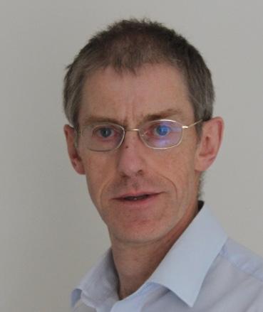
Paul Hooper has spent most of his career working on railway electrification projects. He joined BR as a graduate where he worked on the East Coast Mainline electrification. He has since progressed through many roles, including five years in Hong Kong working for MTR Corp. In recent years he has focused on providing technical support to clients from early project conception, design, testing and commissioning and asset management/ renewals whilst promoting the case for further railway electrification as a means to achieving net zero.
Adam Benwell CEng, MIMechE, MPWI
Chief Engineer, Overhead Contact Systems, Atkins
Adam is a Chartered Engineer and has been working in the rail industry since 2008. Adam has led and managed teams to deliver a wide range of overhead line electrification (OLE) projects through all stages of design delivery globally overseeing the development and deployment of innovative design automation software tools. Adam has been utilising his experience of developing and implementing digital innovation as part of the Central Rail Systems Alliance innovation team with a strategic focus on digital transformation, and in particular introducing a novel OLE digital asset management tool into Network Rail.
Brad Glass CEng, MIMechE
Senior Assistant Engineer,
Atkins
Brad joined Atkins in 2016, in the Overhead Contact Systems (OCS) engineering team working on structural modelling and survey data analysis. He has since transitioned into a digitally focussed role, concentrating on key design automation and survey data processing technologies. Brad now leads software development teams for multiple rail products, including the OLE Static Analysis Toolbox (OLE StAT) in collaboration with Network Rail.
Kevin Hope CEng, FIMechE, FPWI
Engineering & Technical Lead, Infrastructure Measurement Programme, Network Rail
Kevin joined Network Rail in 2006, working in the National Specialist Engineering team dealing with Infrastructure Monitoring. He progressed to Principal Engineer within Network Rail’s Technical Authority and is Network Rail’s leading expert in trainborne Infrastructure Monitoring. Kevin is a Fellow of the PWI and IMechE and is currently Technical and Engineering lead within the Infrastructure Monitoring programme. This programme is responsible for defining the future strategy for Infrastructure Monitoring within Network Rail and the future Great British Railways.
22
AUTHORS:
INTRODUCTION
UK’s commitment to become ‘carbon-neutral’ by 2050, together with the Department for Transport’s, (DfT), aspiration to remove diesel-only traction from UK railways by 2040, is pushing towards significant expansion of the existing electrified network.
The Midland Mainline Electrification, (MMLE), Key Output 1, (KO1), London 2 Corby, (L2C), infrastructure project has delivered 40km / 192STK, (Single Track Kilometres), of newly electrified infrastructure from Bedford to Kettering and Kettering to Corby, using the high-and low-tension derivatives of UK Master Series, (UKMS), overhead line design range respectively. A novel approach to construction assurance and system validation has enabled an unprecedented, for the UK, clean authorisation with no conditions for the completed infrastructure network.
The lessons learned together with the added benefits to risk management, commissioning safety and hand-over asset condition reports can significantly improve the current construction assurance processes, and enable the deployment of a systematic monitoring and predictive maintenance regime as part of a successful rolling programme of electrification.
THE CHALLENGE – ELEMENTS OF THE DESIGN, MANUFACTURING AND CONSTRUCTION ULTIMATELY AFFECT THE PANTOGRAPH TO OLE DYNAMIC INTERFACE PERFORMANCE
At the core of any new OLE infrastructure installation lies the safety, reliability and resilience fundamentally driven and characterised by the pantograph to OLE dynamic interface. Whereas the pantograph type test requirements, [EN 50206-1:2010], and conformance to standards [NTSN-ENE:2021], is common across all systems the asfitted OLE wire profile relative to track after installation ie wire height, (vertical distance), and stagger, (lateral distance), is responsible
for maintaining a uniform contact interface performance across the entire installation. Traditionally, manual surveys, generally via track mounted Height & Stagger laser gauges, are used to measure the height and stagger from the track centreline of suspended catenary and contact wires relative to the track at the beginning and centre point of every span.
The OLE design is governed by a number of system basic design principles which aim to maintain interface performance, proportional to speed, within the specified contact force criteria for different characteristic design features, such as open route, wire gradient, reduced system height, overlaps, cross-overs, etc. The system basic design also dictates as-fitted system tolerances, (geometric constraints), for both the design and construction teams to work within in order to maintain the interface performance. These tolerance bands are used to assure the construction against the manual height and stagger survey, generally universally ±15mm in height and stagger to the design values.
The overall tolerance build-up will affect the OLE system/pantograph interface with excessive statistical variation of the contact forces or with distinct local ‘hard spots’, with the potential to exceed specified requirements. Standards require physical dynamic force testing of the as built infrastructure in order to prove compliance, using expensive and disruptive test trains. Traditional methods for assessing the quality of installed OLE does not provide the level of detail required to ensure the equipment has been installed within tolerance and to demonstrate compliance with standards.
This typically results in problems being identified by the test trains requiring revisits to site to make adjustments to the infrastructure very late in the process. This is a particularly expensive way to pick up any rework / snagging in the construction process and, until MMLE K01, resulted in conditions being added to the project authorisation notice.

23
Figure 1: (a) Mentor contact interface testing NR Service train using a single BW HSA pantograph up to 100mph (tethered pantograph view from within the data acquisition cab), (b) New Measurement Train (NMT), non-contact wire profile monitoring height and stagger at ~250mm increments up to 1000Hz and (c) OVH wizard equipment mounted on the HOPS train monitoring height and stagger at ~500mm increments up to ~24Hz.
A novel approach was used on MMLE KO1 to minimise risk and accelerate the assurance and testing process. The KO1 project used UKMS 125, (max. speed 125mph) in the section from Bedford to Kettering and UKMS 100, (max. speed 100mph) from Kettering to Corby. These are both simple catenary systems from the UKMS range but had not previously been validated to demonstrate compliance with the National Technical Specification Notices, (NTSNs). As a result, the system validation process and commissioning of the OLE progressed in parallel.
The detailed OLE design was based on an absolute coordinate Snakegrid system which enables a high accuracy and low distortion digital visualisation of the entire asset. An early assessment of the design, manufacturing and installation tolerances identified the opportunity to progressively monitor the overall system tolerances at each project stage.
TAKING COGNISANCE OF TOLERANCE BUILD UP EARLY IN THE PROCESS – SPAN LENGTHS
The effect of design span length rounding to the nearest metre, (±1m) was drastically improved by working in an integrated digital twin environment and accounting for the along-track impact of boom structures, such as Twin Track Cantilevers, (TTCs) and position of drop tubes on booms, to the resulting span lengths. Additionally,
dropper allocation tables with 0.1m increments were introduced for the purposes of the project, thus reducing the design span length tolerance to ±0.1m overall.
The OLE structure installation impact to the resulting ‘actual’ span was broken down to pile installation tolerance and cantilever rotation. The pile installation tolerance was determined by the project to 75mm radius around the specified location, (141667-FAF-MANEOH-000003 2017: UK Master Series Installation Manual, Issue 1.2), and combined to the ±20mm accuracy of the GNSS equipment linked to permanent base stations transmitting corrections using a mobile network, provided by Leica SmartNet. The new GPS coordinate position for the out-of-tolerance installed piles was converted back to the Snakegrid coordinates and implemented into the 3D design before final dropper allocation.
It was also considered that two track cantilever, (TTC), boom rotation, particularly at the outermost drop tube support, could affect the ‘actual’ span length to ±0.56m. The same effect on portal support structures is very limited because the boom rotation is governed by the pile installation which had a 95mm radius tolerance and was therefore ignored.
Dropper construction tolerances were maintained to ±5mm by offsite fabrication and the use of in-house jigs to ensure consistency. A further construction approach was taken to improve along-track dropper distribution. Traditionally, when a registration arm heel
Figure 2: Train borne data overlay indicating, (a) interface force measurements, (Mentor BW HSA @100mph), and, (b) static wire profile exceedances, (OLE StAT analysis), at a specific location. (c) Defect 1 is a permanent wire deformation or ‘kink’ which results into a significant contact force trace on the Mentor Data. Defect 2 is a presag deficiency of the CW profile due to a dropper length allocation issue. The Defect 2 effect to the Mentor data is visible, however, the overall impact to the interface performance is not significant. (d) Stagger data appear to have a good correlation between design and as-built profile.
Figure 3: Train borne data overlay indicating the impact to the interface force measurements, (a), (Mentor BW HSA @100mph), and static wire profile exceedances, (b&c), (OLE StAT analysis). Defect 3 is significant wire hogging due to the z-dropper setup, (d). The force applied during setup has an ‘axial’ and ‘vertical’ component resulting in lifting of the contact wire.


THE
SOLUTION
24
setting is not achieved, the droppers are moved along-track to get the correct heel. The new approach considered that droppers spacings were absolute due to the impact to the dynamic interface performance, therefore heel settings were adjusted instead. In some cases, approval was gained from the Network Rail Safety, Technical & Engineering section to adopt increased heel setting tolerances, (for high radial loads).
As a result the impact of design, manufacturing and installation tolerances was minimised in the successive stages of the project, thus enabling an optimised wire profile installation which is the key to the system interface performance with the pantographs. Additionally, the digital delivery and the data-base style design implementation and verification can further enable and support any prospective digital asset management requirements throughout the lifecycle of the asset.
STATIC WIRE PROFILE DEFECTS
As part of the Form E Certificate specified within the Network Rail Standard NR/L2/ELP/27311:2020, a Heights & Staggers survey is required across all the installed wires that are within the pantograph head reach. The analysis of the static OLE wire geometry level of conformance to the basic design provides a clear indication of the entire system setup which will interface with the pantograph. The deviation from the system intended geometry highlights potential locations where the pantograph interface performance is likely to be affected by a poor OLE setup. Some of the regular root causes of measured wire profile deviation are:
• Wire ‘kink’: Contact wire bent out of shape during the installation process.
• Wire tensions: Auto-tensioning Devices may be incorrectly set having an effect on wire presag shape and wave propagation speeds at the interface with the pantograph. The latter effect is more significant at speeds above 100mph.
• Dropper along-track location: a tolerance of ±0.5m is required in the UKMS design manual, (141667-FAF-MAN-EOH-000003) and is affected by a number of factors such as ‘actual’ vs design specified span length and dropper installation strategy. For instance, in a 51m actual span that was designed as a 50m span with the distance from the support to the first dropper specified at 5m, the last dropper distance to the end of the span will be 6m. Effectively, the result of this is a non-symmetric contact wire profile and non-uniform load distribution across the droppers.
• Dropper lengths: Dropper lengths are calculated based on the catenary wire sag profile and their design position within the span. The manufacturing tolerances are normally kept under 5mm and have a minor effect to the static wire profile. The position of the dropper along the span is significantly affected by the catenary wire profile. An ideal dropper at 15m from the start of the span is 30mm longer than required when it is located 16m from the span start. The same phenomenon occurs when catenary support height variation results in the low point of the catenary wire shifting away from the centre of the span.
• In-line insulator components: insulator components such as Section Insulators and Neutral Sections are necessary to enable the safe electrical operation, (electrical distribution), and maintenance of the system. These components are spliced in and are usually heavier and stiffer than the wiring they replace. As a result, they influence the profile and create ‘hard spots’ in the parts of the system where such components are installed.
• Cross-over wires: Cross-overs are important components that enable the rail network to operate. The cross-over wires are usually affected by the added weight of section insulators and often absolute height variation between adjacent tracks. If not set up correctly there is a risk the crossing wire, (merging wire), sags to a lower height in relation to the main wire which can result in poor performance or significant de-wirement risk.
• Overlaps: Overlaps are transition spans between adjacent wire runs. The setup of the wires enables the pantograph head to remain in contact with both in-running and out-of-running wires within the specified section of the overlap span. The setup of overlap spans requires a <50mm circumflex to be achieved at the contact wire resting position. Also the gradients at the overlap and the adjacent spans have to be minimised and remain within the system specifications.
• Additional wires added for electrical requirements: electrical jumper cables are installed connecting the contact wire to the catenary wire and other switching components in the overhead system. These often introduce ‘hard-spots’ to the interface if they are not installed correctly.
• Additional wires: additional wires, known as “Z-droppers”, are introduced on some systems near Mid-Point Anchor, (MPA), locations to prevent the along-track migration of the contact wire relative to the catenary wire. The arrangement of the Z-dropper cable can sometimes result in excessive hogging, (lifting), of the contact wire in the middle of the span resulting in ‘presag’ deficiency. When combined with the wire splicing arrangements onto the contact wire it often impacts the dynamic interface performance.
• Wire height maximum limits: the height limits might result in pantograph Automatic Dropper Device, (ADD), activation when maximum height thresholds are breached.
• Wire stagger maximum limits: excessive stagger might result in the pantograph losing contact with the contact wire resulting in entanglement and de-wirement.
• Gradients: wire gradients relative to track and in absolute coordinates, as well as in adjacent span locations, are often critical to the dynamic interface performance. The shifting of the contact wire centre of mass, (low point), at steep gradients and the vertical wire displacement at localised gradient transitions in open route sections due to track movements or other factors are often the root causes of interface performance issues.
• High-resolution construction assurance
The contractor for the installation on MMLE KO1, SPL Powerlines UK, introduced an alternative approach which offered much more insight to the as-fitted wire profile conformance after the entire OLE system was installed. This approach provided assurance and prioritised snagging activities prior to physical dynamic force

Figure 4: ‘Traffic Light’ dashboard OLE StAT output extract corresponding to the wire run with Defects 1-3. 25
testing using test trains. The approach previously implemented on the Great Western Electrification Project, (GWEP), helped to identify wire profile defects before the introduction of pantographs using a train-borne, non-contact, high-resolution wire profilometry mapping technique. The purpose was not only to spot check the wire conformance to the design, but to gain a continuous uninterrupted view of the suspended wire profile across the entire installed system, not just at the support and mid-span locations checked using tradition measurement methods. The aim was to analyse the static wire profile mapped on the main tracks at a dropper-by-dropper level of granularity to ensure that the wire will always be within the pantograph interface tolerances, (min/max lateral and vertical limits), and identify wire profile deviations within each span that will potentially impact the interface with the pantograph at increasing speeds. The new approach significantly accelerated snagging activities prior to introducing pantographs by focusing on pantograph to OLE interface specific issues and providing comprehensive rectification guidance.
The wire profile acquisition in KO1 was undertaken using the OVH Wizard [D. Wehrhahn] ultrasonic equipment mounted on the High Output Plant System, (HOPS), train operating with 2 channels at 24Hz acquisition speed. The ultrasonic operating principle of the OVH Wizard provides a wide region of interest and can simultaneously map the contact wire and catenary wire, (up to 7m above rail level), but it is limited in terms of the acquisition speed. For the purposes of the high-resolution analysis required, the average speed used during acquisition was 15mph with maximum speed limit up to 20mph (Figure 1 (c)).
For the purposes of the wire analysis, OLE Static Analysis Toolbox, (StAT), was applied to all the mainline wire runs. OLE StAT is a high-resolution static wire profilometry analysis software that has been developed by Network Rail, Atkins and Train-Rail Infrastructure Solutions (T-RIS). The principle of the software is that the contact wire should be slightly distorted around the dropper locations as a result of the droppers supporting the weight of the suspended wire. The vertical extent of these distortions is dependent on the dropper position in the span, the contact wire bending stiffness and tension and weight supported by each dropper. This can be identified using signal processing and ‘peak’ finding techniques, (Baimpas et al.). By identifying the along-track location of the dropper from induced
peaks on the wire, the vertical wire conformance to the intended design wire profile can be correlated.
TRAIN BORN DATA ANALYSIS AND CORRELATION
A combined data analysis and correlation has been applied to map the complete installed wire profile and quantify the impact of each exceedance to the dynamic interface performance of the pantograph:
i. Non-contact static wire profile analysis using OLE StAT based on OVH Wizard data on the main lines – see Figure 1 (c) ii. Dynamic Interface data from instrumented pantograph testing with MENTOR test coach (Single BW HSA @100mph. Instrumented by DB Systemtechnik) – see Figure 1 (a).
A set of combined results with existing static wire profile defects, (OLE StAT), overlaid with interface forces, (Mentor), is illustrated in Figure 2. Figure 2(a) shows the dynamic interface data, (Force - N), with the OLE support locations with existing exceedances highlighted. Figure 2(b) presents the OLE StAT analysed static contact and catenary wire profile, aligned with the Mentor data. The OLE StAT analysis overlaps the basic design intended wire profile, (blue), to the as-built wire profile, (orange), for both catenary and contact wires. The identified dropper locations are highlighted on each wire respectively. Figure 2(c) illustrates a close-up to the contact wire profile only at the locations where Defects 1 & 2 have been located. Defect 1 is a permanent wire deformation or ‘kink’ which results in a significant contact force trace on the Mentor Data. Defect 2 is a presag deficiency of the contact wire profile due to a dropper length allocation issue. The affect of Defect 2 on the Mentor data is visible to a trained eye, however the overall impact to the interface performance is not significant. In the above example, Defect 1 results in a near zero interface force measurement which is likely to incur loss of contact at higher speeds or multiple pantographs. The nature and magnitude of the defect would not have been identified by Heights and Staggers surveys, but is identified due to the high-resolution analysis and the data overlay. Defect 2 results in a 49mm presag instead of a 65mm which does not affect the overall system performance despite exceeding the UKMS 100 system installation tolerances, (vertical and along-track installation tolerance as per 141667-FAF-MAN-EOH-000003 2017).

26
Figure 5: Arthur Flury Single rod Neutral Section, (c) installation on the MML Down Fast showing the resulting impact to the interface contact force collected by MENTOR, (a) and analysed static wire profile, (b) using OLE StAT.
The data analysis is therefore crucial to identify any critical locations in tandem with quantifying the performance impact, which can be beneficial to monitor and maintain the infrastructure at later lifecycle stages.
Figure 3 introduces the combined analysis and correlation between static wire profile deviation and the resulting dynamic interface performance for MMLE at a Mid-point anchor, (MPA), location. Defect 3 is a noticeable hogging of the wire as a result of a z-dropper arrangement installation. The additional wire connects the catenary wire to the contact wire either side of the MPA, as illustrated in Figure 3(d) schematic. The additional wire is also attached to the droppers that it transverses and 1kN pretension is applied. The purpose of the z-dropper is to prevent along-track migration of the contact wire relative to the catenary. The impact of the added weight and non-axial loads into the system affects the wire profile and the resultant interface performance is clearly evident in the MENTOR data, (the spikes in Figure 3(a)).
OLE StAT additionally offers a high-level dashboard summary of the wire analysis introducing a ‘traffic light’ system based on the specified installation or maintenance thresholds. The OLE StAT dashboard output in Figure 4 enables a high-level system conformance check, which provides a comprehensive schedule for snagging or maintenance interventions to be passed on to the installer/maintainer. Each row of the dashboard corresponds to a number of selected parameters that are checked and presented. Alarm thresholds can be specified depending on installation or maintenance requirements. Figure 4 presents a small selection of the possible outputs including start and end of each span location, span type, contact height, stagger, catenary height, gradient and presag. Additionally, it presents support deviation which indicates the maximum difference in-height between the design and the actual achieved heights. Lastly, in-span deviation is a gauge of the contact wire profile shape conformance to the system basic design principles separate to the height shift at the supports. Areas with increased standard deviation of the contact force normally indicate that the shape of the OLE differs from the system design principles which is quantified by the in-span deviation parameter.
Defects are classified based on the measurable impact to the static wire profile geometry. The level of static wire profilometry deviation can be directly attributed to the corresponding dynamic interface data collected to instruct and prioritise site-interventions. Therefore, a risk-based approach leads to component specific interventions at distinct locations whereas previous interventions are normally instructed across entire areas. Subsequently, ‘boots on ballast’ time is significantly reduced with the required intervention supported by
comprehensive component adjustment work schedules. Crucially, the improvements directly target the interface performance, and the corresponding benefit can be directly assessed and quantified which further enables the monitoring of the OLE asset throughout its lifecycle.
Several other parameters are available and can be checked and flagged to the asset manager. These can be missing/broken droppers, transition gradients, overlap conformance, location specific design parameters, dropper along-track position and alongtrack location tolerance, actual span length, lateral deviation etc. Lastly, in the case of OVH Wizard acquisition where both messenger and contact wires are mapped, specific dropper lengths can be identified and issued to the maintainer to enable more targeted onsite intervention.
Figure 5 illustrates another example concerning the introduction of insulator components spliced within the OLE wire infrastructure in the Down Fast at Sharnbrook, UK. Single rod Arthur Flurry Neutral Sections are capable of operation up to 125mph, but they are acknowledged as rigid components with separate allowances in the applicable interface performance criteria specified by the standards for contact force. The static wire profilometry data were collected in July 2020 by OVH Wizard and in March 2021 by Network Rail’s New Measurement Train, (NMT). The analysis is carried out by OLE StAT for both data sets. The analysis indicates additional hogging has been progressively added by maintenance teams between the scan dates in order to optimise the dynamic interface performance. The dynamic interface data was collected by the Mentor test train in March 2021. The NMT data enabled an up-to-date view of the system following on-site adjustments post the original installation. The overall forces collected at 100mph with a single BW HSA pantograph are within acceptable limits.
Crucially, this approach provides a high-resolution construction assurance method, introduces a system-based assessment of the accumulated tolerances and can accurately predict the impact to the prospective interface performance. Provided that the system mapping is effectively mandated and specified as an integral part of the installation process, a number of benefits can be readily realised:
• Using a contactless measurement system enables targeted wiring adjustments that directly improve the dynamic interface performance, (mechanical interaction of the OLE with the pantograph), prior to operation with a pantograph. This could potentially prevent catastrophic failure. Additionally, this flexible approach can progress in tandem with construction which will further accelerate later assurance activities, (eg non-contact
Figure 6 Route schematic showing the tracks kilometrage at crossings, Sharnbrook tunnel, and the transition from the UKMS 125 system to the UKMS 100 at Kettering.

27
measurements can be carried out by Road Rail Vehicles, (RRVs), immediately following installation as part of the wiring activity);
• Systematic approach to construction assurance based on trainborne data, which will enable faster sign-off for route testing and third-party assurance evidence to the installation quality;
• Gain direct insight to dropper compliance which improves high-speed operation and accelerates on-site interventions. The mapping can be specified to progress in tandem with the installation which will eliminate post completion interventions;
• Map the entire network and hand-over to the Route Asset Manager to be used as the baseline for Asset Condition Monitoring strategy and predictive maintenance.
INTRODUCE PANTOGRAPHS FOR THE FIRST TIME TO THE OLE WIRE ACROSS THE ENTIRE INSTALLATION - MECHANICAL DYNAMIC TESTING
During the early post-installation stage, mechanical dynamic testing was carried out across the infrastructure prior to the energisation using diesel powered locomotives with instrumented pantographs. The testing took place before energisation covering all lines from Bedford to Kettering, (B2K), and Kettering to Corby, (K2C), with progressive speeds at 30, 60 and 90mph, (see Figure 6). The live-force feed was assessed after each pass before a decision that the infrastructure was safe to operate at higher speed. The accompanying information from the OLE StAT analysed wire runs was used for the interpretation of interface forces aiming to associate specific force sample events with specific infrastructure features.
The review of interface force results quickly indicated a number of MPA locations that gave suboptimal performance similar to Figure 3, but the interface forces did not exceed the NTSN limits. Subsequent testing was carried out after removing MPA z-dropper arrangements in specific locations to establish the performance and later enable a decision to maintain, improve or remove the z-dropper arrangements. The purpose of variable speed mechanical testing prior to energisation was to identify and eliminate asset defects and exceedances sooner. Additionally, the ability to overlay static geometry data and dynamic instrumented pantograph data enabled a high degree of confidence during on-board mechanical test data interpretation and a managed risk while attempting high-speed passes.
A similar tactic was previously used during testing at Steventon, UK on the Great Western Mainline, (Baimpas et al.), where instrumented pantograph testing started at 60mph and progressively achieved 125mph. The on-board data analysis was correlated to the Dynamic – Rail System Simulation, (D-RSS), from T-RIS, OLE to pantograph interface dynamic modelling prediction. By achieving sufficient correlation at each speed, the decision to proceed to the higher increment could be made with confidence.
TESTING WITH ALTERNATIVE PANTOGRAPH ARRANGEMENT AND SUBSTITUTE WITH DYNAMIC MODELLING
As an interim validation step in the MMLE KO1 project, instrumented pantograph data from the MENTOR vehicle within a Network Rail test train formation was used to achieve system validation for the UKMS 125 and 100 system derivatives.
The measurements were performed with a single pan formation instead of the multiple pantograph arrangements. However, the results up to 100mph tested indicated that the dynamic interface system performance was at such a level where multiple pantograph operation would be likely to remain within the NTSN and EN 50367 specified thresholds. This decision was supported by the as-fitted wire profile evidence provided as a result of mapping and analysing the entire network using OLE StAT. Therefore, all identified locations with higher contact force traces were cross correlated for the level of compliance to the design and associated installation tolerances. It was further identified, as part of this exercise, that by simulating the as-fitted wire profile into the finite element interface model D-RSS from T-RIS created a high level of correlation between the measured interface forces using instrumented pantographs and the
simulated D-RSS interface performance. The modelling typically achieved correlation greater than 95% even in cases of identified system ‘hard spots’ such as neutral sections, cross-overs and bridges. It is highlighted that the force correlation achieved is due to modelling with the exact as-fitted asset geometry and implementing into the model various installation set-up, as described within the system manuals. These added features are specific to the UK network and model the OLE and pantograph to a higher level of detail than the models specified by the EN 50318 standard. As a result, these interface models can reliably be used to accurately predict system performance, including for a range of rolling stock formations, pantograph types and speeds, without the need for physical testing.
This approach, if implemented in future, could allow authorisation based on the modelling of the as-built infrastructure instead of expensive, time consuming and disruptive physical testing, derisking the authorisation process and possibly saving 6-12 months from the programme at the end of a project.
CONCLUSION
Electrification in the UK in recent years has been considered expensive and projects have been beset by problems. There have been many lessons learned and lessons continue to be learned within the projects, but one of the key areas where the industry has struggled has been hand back and authorisation of the new OLE. MMLE KO1 identified this early and through the full lifecycle of the project introduced what could be seen as minor improvements in focussing on construction tolerance at design stage, gaining a higher level of understanding of the as-built asset and testing the asset earlier in the process ahead of energisation. This provided a higher level of confidence and assurance alongside the rigorous physical testing of the infrastructure to contribute towards the electrification project gaining an unprecedented, for the UK in the past 10 years, clean authorisation, with no conditions for the completed infrastructure network.
This work opens up further opportunities to provide greater efficiencies for electrification projects in the UK.
REFERENCES
EN 50206-1:2010: Railway applications - Rolling stockPantographs: Characteristics and tests - Part 1: Pantographs for main line vehicles
NTSN ENE 2021: Railway Interoperability – The Railways (Interoperability) Regulations 2011
NR/L2/ELP/27311:2020: Engineering Assurance Requirements for the Design and Implementation of Electrical Power Engineering
OVH Wizard: Mobile, Non-contact Measuring System for Detection of the Contact Wire Position by Dr D. Wehrhahn
141667-FAF-MAN-EOH-000003 2017: UK Master Series Installation Manual, Issue 1.2
Nikolaos Baimpas, Eric Le Bourhis, Sophie Eve, Dominique Thiaudière, Christopher Hardie, Alexander M. Korsunsky: ‘Stress evaluation in thin films: Micro-focus synchrotron X-ray diffraction combined with focused ion beam patterning for do evaluation’ (2013). Thin Solid Films http://dx.doi.org/10.1016/j.tsf.2013.07.019
Nikolaos Baimpas, Peter Dearman, Simon Warren, Matthew Leathard, Brad Glass, Garry Keenor, ‘Great Western railway electrification, UK: pantograph interface model boosts speed’ (2020). Volume 173 Issue 6, November 2020, pp. 19-27, Special issue on Great Western railway electrification, UK https://doi. org/10.1680/jcien.19.00056

28
PWI TECHNICAL SEMINAR
TOMORROW’S RAIL SAFETY TODAY
On our railway, the safety of those who work on the infrastructure and of the infrastructure itself are of vital importance to the delivery of a reliable railway for our passengers and freight customers. Intelligent Infrastructure - earthworks and structures, track, power, electrification, control, and train systemsintegrated with diagnostic and predictive ‘decision support tools’ and coupled with smarter inspections, make for a railway where we can predict the work we need to do and proactively plan to do that work in the safest possible way.
Modern safety equipment that significantly reduces the risk of human error is now available across our network to keep infrastructure workers and trains separate and safe. Bring predictive work schedules and this safety equipment together via a simple-to-use planning and ‘Safe Work Pack’ system and deploy site safety leaders trained with the most up-to-date human factor skills, and we have tomorrow’s safety expectations today!
The conference will show how this vision can be our reality now. Delegates will be encouraged to consider how the techniques presented can be embraced and applied widely to real world operations, to keep infrastructure workers and railway infrastructure as safe as they can possibly be.


The future is here - and ready to use...

26 MAY 2022 AUSTIN COURT, BIRMINGHAM BOOKING NOW OPEN: www.thepwi.org £80 MEMBER £150 NON-MEMBER £10 STUDENTS SPONSORSHIP AND EXHIBITOR SPACE AVAILABLE. Contact 01277 230 031 / secretary@thepwi.org Attend this hybrid seminar in-person or virtually. Full details on the website. SPONSORED BY 29
Whole life carbon management in the rail industry
Nick Rothwell BSc, MSc, PIEMA Sustainability Consultant
Hector Lyons BSc (Hons) Assistant Sustainability and Carbon Consultant
With a background in Climate Science from University of Bristol, Nick has spent several years as a consultant in Atkins’ sustainability team and has developed considerable expertise in relation to whole life carbon management.

Nick has led carbon management projects both in the UK and internationally across various sectors including, road, aviation, water and rail. He is passionate about working with clients to find new and innovative approaches to minimising carbon within their projects and supporting them to meet their net zero goals.
Before joining Atkins, Hector graduated from Oxford Brookes University, completing a dissertation focusing on sustainability within the workplace environment.

Post-university he worked in agriculture, carrying out sustainable regeneration and biodiversity enhancement in farming. From this Hector joined Atkins as an Assistant Carbon & Sustainability Consultant where he has been involved in multiple projects including carbon assessments of rail and road infrastructure.
Dr. Mohammad Safari Baghsorkhi
BEng (Hons), MSc, PhD, CEng, MPWI
Principal Track Engineer
Mohammad is a Principal Track Consultant working for Atkins. He is a Chartered Engineer and Professional Registration Reviewer with the Permanent Way Institution. His experience in rail and civil engineering covers design, maintenance, and asset management. He has a PhD in Railway Engineering and his PhD aimed to optimise and develop an improved understanding of the impact of sleeper, ballast, and sleeper/ballast interface modifications on the performance of conventional ballasted track and formation.
Having worked previously as a sustainability researcher, Mohammad has a strong interest in sustainability and climate change which is one of the greatest challenges faced by the world today.

INTRODUCTION
Climate change, accelerated by anthropogenic greenhouse gas (GHG) emissions, is one of the critical global issues within today’s society. The effects of climate change are already visible, from rising sea levels to long term shifts in weather patterns and increased temperatures. Meeting net zero emissions targets is therefore paramount to avoiding further impacts and potentially reversing the changes that we are already seeing around the world.
The transport sector represents around 27% of the UK’s GHG emissions1. Traditionally the focus of carbon reduction efforts in the transport industry has been on operational emissions from fuel combustion in vehicles, however as the net zero agenda grows in prominence and vehicles decarbonise through electrification, whole life carbon of transport infrastructure is becoming increasingly important.
Whole life carbon is the sum of total greenhouse gas emissions that occur throughout the lifecycle of a project, from the emissions released during the extraction of raw materials and manufacturing of products, the transport of products to the construction site and emissions released during the construction process, as well as operation and maintenance and finally end-of-life emissions, as demonstrated in figure 1.
This article explores whole life carbon management for the rail industry in the context of the wider net zero agenda. It aims to
demystify carbon management and quantification to help people in the rail industry embed sustainability best practice. Guidance is provided for effective use of carbon calculators such as the RSSB Rail Carbon Tool2 supported by a case study of an example of Atkins’ experience in managing carbon on a rail infrastructure project and quantifying the benefits using the Rail Carbon Tool.
UK NET ZERO TARGETS
Responding to the threat of catastrophic climate change requires coordinated action to reduce greenhouse gas (GHG) emissions in order to meet targets set out in the Paris Agreement of 2015. These targets aim to keep global temperature rise this century below 2oC (above pre-industrial levels) and encourage efforts to limit the temperature increase even further to 1.5oC3. In response, the UK statutory target for reducing GHG emissions was strengthened in May 2019 to focus on achieving Net Zero by 2050 4
The Committee on Climate Change (CCC) defines ‘Net-Zero’ emissions as the point when the “total of active removals of carbon from the atmosphere offsets any remaining emissions from the rest of the economy”5. In practice, this means that to achieve net zero, emissions must be reduced as far as possible, with any remaining emissions being offset by active removals (eg land use change to forests, grassland etc.). Understanding how to identify carbon emissions sources and then how to effectively manage those sources to create carbon reductions, is therefore paramount to achieving net zero.
30
AUTHORS:
GHG EMISSIONS IN THE RAIL INDUSTRY
Rail is one of the lowest carbon forms of transport, accounting for just 1.4% of the UK’s domestic transport emissions in 2019, despite 9% of transport being carried out on the UK’s railways6
Over 40% of the UK’s railways are already electrified, enabling the transport of passengers and goods with minimal GHG emissions being released. As electrification of the rail network extends, and the National Grid continues to decarbonise, this mode of transport is becoming even less carbon intensive.
The Department for Transport’s top priorities from the Rail Environment Policy Statement are:
• Achieve net zero GHG emissions from rail by 2050 (including whole life carbon emissions).
• Remove all diesel-only trains from the rail network by 2040.
• Sustainable, deliverable programme of electrification that delivers a higher performing, net zero railway.
In order to achieve these ambitions, and as operational emissions are actively being reduced across the rail network, reducing whole life emissions associated with rail infrastructure is becoming even more important. Emissions associated with the construction and maintenance of rail infrastructure will become the main source of emissions once trains are fully electrified.
The Department for Transport’s plan ‘Decarbonising transport: a greener, better Britain’7 recognises this, stating that a joined-up approach across the supply chain to managing whole life emissions will be critical to achieving net zero across the non-traction elements of UK railways.
The rail industry’s 2021 proposal for a cleaner and greener future8 states that whole life carbon reductions will be achieved by including carbon reduction targets within rail management contracts and investing in zero carbon infrastructure along with providing Great British Railways with responsibility for carbon monitoring.
Furthermore, Network Rail’s Environmental & Social Minimum Requirements9 call for a capital carbon assessment to be carried out for all projects with a capital value of over £1million. These assessments must use the RSSB Rail Carbon Tool (RCT) to develop a baseline and identify opportunities for whole life carbon reduction10
Processes for quantifying and managing carbon in rail infrastructure therefore need to be defined, understood, and implemented to enable effective reductions of whole life carbon.
MANAGING WHOLE LIFE CARBON IN RAIL
The key technical standard that provides guidance for management of whole life carbon in the infrastructure industry is PAS 208011. PAS 2080 is a voluntary standard and aims to improve the management of carbon throughout the supply chain, allowing evidence-based decisions to be made and the identification of carbon reduction opportunities12. PAS 2080 provides a common framework for the whole supply chain, encouraging the right behaviours and approaches to deliver reduced carbon and cost.
The key requirements of an effective carbon management system, as defined by PAS 2080 are:
• Show clear leadership: Set an organisational strategy for carbon management and assign roles and responsibilities to individuals/teams so they understand the part they play in reducing carbon.
• Embrace a culture of challenge and change: Communicate the importance of carbon management to project teams and the supply chain and encourage challenging of the status quo.
• Set bold targets: Set challenging carbon reduction targets against a defined baseline and establish KPIs to monitor emissions during project delivery.
• Develop a carbon management process integrated within standard project delivery: Ensure carbon information feeds into decision making from the earliest project stages.
• Engage the value chain early: Collaborate with the whole value chain from the earliest project stages to share carbon objectives and identify innovative low carbon solutions, removing any constraints to collaboration.
• Establish an accurate carbon accounting procedure: Use relevant tools and processes to quantify and report carbon throughout project delivery to feed into decision making.
• Promote continual improvement of the process: Seek the input of the whole supply chain to improving the carbon management process.
Following the principles of PAS 2080 on rail infrastructure projects will allow for innovation, carbon, and cost reduction. It ensures consistency within infrastructure delivery, making carbon visible across the supply chain, and ultimately will lead to low carbon solutions. Developing a carbon management system for projects, aligned with PAS 2080, is therefore strongly recommended.
Tools, such as the Rail Carbon Tool, can be used to support carbon management throughout project delivery and chapter 7 of PAS 2080 provides a methodology for effective use of such tools.
Figure 1: End-to-end emissions sources across the whole life of a construction project.

INFRASTRUCTURE
31
INTEGRATING CARBON MANAGEMENT INTO PROJECT DELIVERY
To ensure that carbon is considered at all project decision points alongside other key factors, such as cost and programme, carbon must be embedded within the delivery of a project from the earliest stages. The 2013 Infrastructure Carbon Review13 illustrates this importance through the infrastructure carbon reduction hierarchy, as set out in figure 2.
Carbon can be reduced at any point during project delivery but the proportion of emissions that can be reduced decreases over time. The earlier that whole life carbon is considered in project decision making, the greater the potential to reduce emissions. The carbon reduction hierarchy forms the basis of effective management of whole life carbon within the delivery of assets or programmes of work.
In practice, the carbon reduction hierarchy provides a framework for decision making that will result in innovation and low carbon results:
• Build Nothing: Evaluate the basic need for an asset and/ or programme of works and explore alternative solutions to achieve stated project aims.
• Build Less: Evaluate the potential for re-using and/or refurbishing existing assets to reduce the extent of new construction required.
• Build Clever: Consider the use of innovative approaches or low carbon solutions to minimise resource consumption during construction operation and use, and build infrastructure that has been designed for easy decommissioning and reuse/ recycling.
• Build efficiently: Use technologies that reduce resource consumption during construction, operation and end of life14
Working closely with stakeholders including clients, project teams and the supply chain is essential to embedding the carbon reduction hierarchy into all areas of project planning and delivery. This can be achieved through in-depth discussions and holding workshops that allow for supply chain collaboration where all parties can gain an understanding and contribute ideas.
Using the carbon reduction hierarchy as the framework to these conversations, and as general principles to follow during design and construction, helps to instil a challenge culture throughout project delivery where carbon reduction is considered at every stage. By embedding the principles of PAS 2080 and the carbon reduction hierarchy within project delivery, substantial carbon reduction opportunities are unlocked. These opportunities can be explored,

options can be compared, and whole project reporting can be carried out by assessing carbon using carbon calculation tools, such as the Rail Carbon Tool.
WHOLE LIFE CARBON ASSESSMENT
FUNDAMENTALS
Calculating whole life carbon emissions is often perceived as being a complicated process, however the basic calculation is very simple. At its core, carbon calculation is simply multiplying project activity data (eg a quantity of material) by a relevant carbon factor. A carbon factor is a coefficient representing the average emissions associated with a single unit of a specific source (eg the average emissions associated with the production of 1 tonne of concrete). Carbon factors are provided by various carbon factor libraries and cover all processes across the project lifecycle including products/materials, vehicle transport, construction processes, fuel, energy and water use as well as end of life processes. Carbon factors are produced according to specific technical standards, such as BS EN 1580415, to ensure consistency and accuracy.
In some instances, product manufacturers may provide a carbon factor that has been calculated for a specific product and is reported in an Environmental Product Declaration (EPD). EPDs are the most accurate form of carbon factor and therefore should be prioritised wherever possible.
Carbon emissions factors and calculated emissions from project activities are expressed in carbon dioxide equivalents (CO2e) per unit (eg per tonne). CO2e represents the global warming potential of all GHGs released by an activity, put in the context of carbon emissions to enable easy comparison.
CARBON MODELLING AND CARBON TOOLS
To carry out a robust carbon assessment of a project or a project option, there are a number of technical components that must be in place and understood, including:
• A thorough understanding of the life cycle of the project/asset, and where the measurable emissions sources exist.
• Data sources, including project-specific input data as well as appropriate carbon emissions factors.
• A robust assessment methodology that is aligned with relevant technical standards (eg PAS 2080).
• A defined system boundary, outlining the physical and geographical boundaries to be included in the assessment as well as all inclusions and exclusions within that boundary.
Figure 2: The carbon reduction hierarchy. Source: Infrastructure Carbon Review – 2013. 32
•
A reference study period, which defines the time-period for the assessment, and consequently the range of operational activities for which emissions will be accounted for (eg energy required during operational lifetime, maintenance/replacement requirements).
BENEFITS OF QUANTIFYING EMISSIONS
A wealth of benefits arise from calculating whole life carbon emissions within projects. Carbon calculation is most effective when feeding into the optioneering process of project development. Understanding the whole life carbon impact of each project option enables teams to make sustainable decisions.
Calculating emissions also enables project teams to fully understand where the majority of carbon is occurring within a project or option, often referred to as the carbon hotspots. Efforts can then be focussed on reducing these large emissions sources where the potential for reduction is greatest.
Carbon quantification can also be particularly useful when making a business case for more sustainable solutions; if a sustainable product has greater upfront costs then understanding the potential emissions savings helps to make a case for the additional upfront capital expenditure. Similarly, calculating whole life carbon ensures that the lifetime of a product/asset is considered, and therefore may enable teams to select options that have greater upfront costs but will save money over the lifetime of the project as they last longer or require less maintenance.
LEVELS OF QUANTIFICATION
There are varying levels of carbon quantification that can be followed; depending on the size and budget of the project and the project stage, certain approaches are likely to be more relevant than others.
For larger projects (eg Network Rail projects with a capital value of over £1million) it is likely that a fully quantified carbon model is required and from early stages of the project lifecycle covering the whole life of the project, and comparing emissions reductions against an agreed project baseline.
In some instances, in particular when feeding into particular decisions within project delivery, it may be appropriate to carry out a more targeted assessment. This may be a quantified carbon model covering only certain stages of the assets’ life cycles that are likely to have a material impact on the results of a comparison between options. For example, when comparing the carbon associated with two options with the same expected lifespan and maintenance requirements, it may only be necessary to quantify the impact of the materials, transport and construction to understand which will have the larger whole life carbon impact.
Projects at very early stages or smaller projects may not require a quantified carbon model in order to make low-carbon decisions. In these instances, qualitative data may be utilized. This may take the form of discussions regarding the project options and which ones will use the most materials, have the shortest lifespan or will take the longest to build. Discussions may also be focussed on a single option, framed around the carbon reduction hierarchy and identifying ways to make assets smaller, or use alternative materials.
Whenever a qualitative approach is taken, the whole life impact should still be considered, to ensure that all aspects that will make a material impact are accounted for. Such discussions are most effective when they are collaborative and involve supply chain stakeholders and are often aided by the presence of a carbon management expert, however this is not a necessity as long as the principles of the carbon reduction hierarchy are followed and the whole life impact is considered.
Regardless of whether a quantitative or qualitative approach is followed, it is important to track decisions that are made so the processes and resulting carbon savings can be documented. Furthermore, when data is limited at early project stages, if
documented, these early decisions may be quantified at later stages when data is more available so the total emissions reduction can be reported.
GATHERING DATA
When carrying out a quantitative assessment, data should be gathered from all potential emissions sources as per figure 1. Ensuring that the various disciplines within project teams know they are required to provide data, in what format it should be provided and when it will be required streamlines the process and ensures consistency.
Whilst some data may be difficult to acquire and may require teams to make assumptions based on experience and technical judgement, often a lot of the data required is already captured as part of traditional project delivery. For example, bills of quantities, costing exercises and construction programmes all create usable datasets that feed into carbon calculation. Planning data sources and working with teams to understand what data will be available is therefore an important exercise.
Accurate whole life data is most effectively sourced through collaboration between supply chain stakeholders, each providing data relevant to their particular specialist area (eg contractors providing fuel/energy use data for the construction process). Again, it is important for stakeholders to understand that they will be required to provide data and in what format to make the process as streamlined as possible.
At very early project stages, it may not be possible to gather projectspecific data across the whole life cycle of the project. In these cases, previous project examples may be utilised, in combination with assumptions made through expert technical judgement or standard data provided by technical standards or industry bestpractice. Where this is the case, this data should be updated at the next iteration of assessment by project-specific data where possible, and the baseline adjusted where necessary.
THE RAIL CARBON TOOL
The RSSB Rail Carbon tool (RCT) is a freely available, web-based, carbon assessment tool for the rail industry, hosted and provided by RSSB and originally developed by Atkins. Premium carbon factor libraries for the infrastructure industry, including the Inventory of Carbon & Energy (ICE) database16 are embedded within the RCT, enabling the assessment of whole life carbon for rail projects. The RCT is simple to use and enables all levels of carbon quantification to be carried out, from small scale targeted assessments to holistic whole life assessment for whole project reporting. When the correct methodology is followed, the Rail Carbon Tool can be used to carry out carbon calculations that adhere to the quantification requirements of PAS 2080.
For further information and training regarding use of the RCT, please refer to the RSSB website17
CASE STUDY: SOHAM STATION REDEVELOPMENT
A CARBON ASSESSMENT USING THE RAIL CARBON TOOL SITUATION
Soham Station in Ely, Cambridgeshire, previously operated on the Ipswich to Ely line serving the town of Soham, until its closure in the 1960s. Following a long campaign to rebuild it, the station was reopened in December 2021. The new station reconnects the local community to the rail network supporting further investment as part of Cambridgeshire & Peterborough Combined Authority’s vision for the wider area18
Atkins were involved in project design optioneering and used the principles of PAS 2080 to make low-carbon decisions and then quantified carbon in the Rail Carbon Tool, feeding into the wider options appraisal.
33
The client, Network Rail, needed to decide what type of platform should be built at the station as well as understand the carbon benefits of design decisions that were made. An appraisal of five platform options was required considering cost, constructability, and carbon, and a full project assessment was required to quantify the carbon benefit of design changes throughout options appraisal stage.
ATKINS SOLUTIONS AND ADDED VALUE
Atkins’ carbon experts and engineering design team worked in collaboration to gather life cycle inventory data of the five platform options to feed into a targeted carbon assessment using the Rail Carbon Tool, comparing each option. The options included:
1. Red brick, crosswall and plank platform
2. Steel modular platform
3. Glass Reinforced Plastic (GRP) modular platform
4. Polystyrene modular platform
5. Concrete modular platform
The results of the assessment fed into a wider options appraisal considering various factors including cost, constructability, and sustainability.
Additional to the platform assessment, Atkins’ sustainability team worked with the designers to identify sustainable, low-carbon solutions within all aspects of the overall design, by integrating the principles of the carbon reduction hierarchy and by carrying out carbon reduction workshops.
At later stages, once the preferred platform option had been chosen, a full carbon model was developed covering the whole station, including the station footbridge, access road and car park, shelters, signalling structures and the platform. The intention of the full model was to demonstrate how carbon had been reduced throughout the options appraisal stage.
Atkins’ carbon specialists also used the assessment to identify carbon hotspots within the overall station design and worked with the design team to identify further opportunities to reduce carbon associated with those hotspots in later stages.
METHODOLOGY
The carbon assessments carried out throughout project delivery were conducted using the Rail Carbon Tool, in line with Network Rail’s environment standard (NR/L2/ENV/015). The assessment methodology followed the principles set out in section 7 of PAS 2080: Carbon Management in Infrastructure on whole life carbon quantification.
FINDINGS
Atkins identified through the targeted platforms assessment, that the Polystyrene Modular solution had the lowest associated carbon emissions, as illustrated in figure 3.
Key benefits and success factors
• The carbon assessments provided the information necessary to enable design decisions that were significantly more informed and justifiable from a sustainability perspective. A key factor in this was the transparent assessment methodology, using direct project and supplier data.
• Atkins used the Rail Carbon Tool to quantify carbon between different platform components, demonstrating to the client that the most carbon efficient solution (polystyrene modular) delivered a carbon reduction of 49% against the baseline option (crosswall and plank).

• Based on the results of the platforms carbon assessment and the wider aspects of the options appraisal, the client chose the lowest carbon platform solution, polystyrene modular, which contributed a significant amount to the overall carbon reduction of the station design.
• Through embedding the principles of the carbon reduction hierarchy into the design decision making process, Atkins were able to achieve further carbon reductions across the whole station design.
• An overall carbon reduction of 18% was achieved throughout the options selection stage, when compared to the baseline design from the previous stage.
From the in-depth comparison between options and the identification of carbon hotspots within the design, Atkins’ carbon experts were able to make the following recommendations to the project team:
CLIENT ISSUES
Figure 3: Platform options carbon assessment comparison. 34
• Consideration should be given to potential opportunities to reduce the volumes of materials in the design option taken forward, aligning with the ‘Build Less’ principle of the carbon reduction hierarchy.
• Consideration of opportunities to transport materials by rail, wherever possible, as rail transport has a lower carbon intensity than road.
• Seek to identify alternative materials with a lower carbon intensity, wherever possible, aligning with the ‘Build Clever’ principle of the carbon reduction hierarchy. Opportunities may exist to utilise recycled, or site won materials in the design which would reduce the overall carbon impact.
• Explore opportunities to optimise the construction process by reducing the plant machinery and vehicles required and/or their time on site, aligning with the ‘Build Efficiently’ principle of the carbon reduction hierarchy. Choosing electric plant machinery and vehicles and using renewable energy wherever possible on site should also be considered.
• A large opportunity exists to reduce carbon emissions if materials are recycled at their end-of-life. Implementing project components so they are as recyclable as possible will therefore increase the opportunity to minimise carbon through recycling at end-of-life.
ATKINS’ APPROACH TO WHOLE LIFE CARBON MANAGEMENT
As part of the SNC Lavalin group, Atkins made a commitment in May 2021 to achieve net zero by 2030. Our approach to whole life carbon management forms part of our contribution to the SNC Lavalin purpose to “create sustainable solutions that connect people, data and technology to design, deliver and operate the most complex projects”.
Our approach is a core part of our Engineering Net Zero19 initiative, with a vision of “embedding sustainability in everything we do, progressing attitudes within the industry and aspiring to make all schemes in which we are involved net zero by 2030.”
We are committed to offering our clients ambitious design options and advice that are fully compatible with Net Zero outcomes. We aim to design out carbon at every opportunity, with our methodology focused on driving engagement, collaboration, and innovation amongst all our project partners, including asset owners, designers, construction teams, operators and materials suppliers. At every project stage we strive to challenge carbon intensive materials and methods and push the boundaries of innovation to enable our clients to develop solutions that deliver long-term positive change. We channel our low-carbon engineering experience into pioneering solutions for faster decarbonisation of businesses, sectors and regions at scale, to deliver sustainable economic growth.
REFERENCES
1. Transport and Environment Statistics 2021 Annual report (2021). [online] Available at: https://assets.publishing.service.gov.uk/ government/uploads/system/uploads/attachment_data/file/984685/ transport-and-environment-statistics-2021.pdf (Accessed: 10 January 2022)
2. Rail Safety and Standards Board, Rail Carbon Tool (2021). [online] Available at: https://www.rssb.co.uk/en/sustainability/rail-carbon-tool (Accessed: 10 January 2022)
3. Intergovernmental Panel on Climate Change, Global Warming of 1.5 ºC (2018). [online] Available at: https://www.ipcc.ch/sr15/ (Accessed: 10 January 2022)
4. The Climate Change Act 2008 (2050 Target Amendment) Order 2019 (2019). [online] Available at: http://www.legislation.gov.uk/ ukdsi/2019/9780111187654 (Accessed: 10 January 2022)
5. Climate Change Committee, Net Zero Repots (2019). [online] Available at: https://www.theccc.org.uk/publication/net-zero-the-ukscontribution-to-stopping-global-warming/ (Accessed: 10 January 2022)
6. Department for Transport, Rail Environment Policy Statement (2021). [online] Available at: https://assets.publishing.service.gov.uk/ government/uploads/system/uploads/attachment_data/file/1002166/ rail-environment-policy-statement.pdf (Accessed: 10 January 2022)
7. Department for Transport, Decarbonising Transport (2021). [online] Available at: https://assets.publishing.service.gov.uk/ government/uploads/system/uploads/attachment_data/file/1009448/ decarbonising-transport-a-better-greener-britain.pdf (Accessed: 10 January 2022)
8. Local Government Association, The importance of rail in meeting the UK’s net zero ambitions. [online] Available at: https://www.local. gov.uk/andy-bagnall-rail-net-zero (Accessed: 10 January 2022)
9. Network Rail, Environment & Social Minimum Requirements –Deliverables (NR/GN/ESD36) (2020) [online] Available at: https:// safety.networkrail.co.uk/wp-content/uploads/2020/02/NR_GN_ ESD36-Environmental-and-Social-Minimum-RequirementsDeliverables.pdf (Accessed: 10 January 2022)
10. Network Rail NR/L2/ENV/015 ISSUE 9 (Clause 6.4.2)Environment and Social Minimum Requirements for ProjectsDesign and Construction - Compliance Date: 4 September 2021.
11. British Standards Institution, PAS 2080: Carbon management in infrastructure (2016). [online] Available at: https://shop.bsigroup.com/ products/carbon-management-in-infrastructure/standard (Accessed: 10 January 2022)
12. The Green Construction Board, Guidance Document for PAS 2080 (2016). [online] Available at: Guidance-Documentfor-PAS2080_vFinal.pdf (constructionleadershipcouncil.co.uk) (Accessed: 10 January 2022)
13. HM Treasury, Infrastructure Carbon Review (2013). [online] Available at: https://assets.publishing.service.gov.uk/government/ uploads/system/uploads/attachment_data/file/260710/ infrastructure_carbon_review_251113.pdf (Accessed: 10 January 2022)
14. Procurement Requirements for Carbon Reduction in Infrastructure Construction Projects - An International Case Study (2019). [online] Available at: https://www.diva-portal.org/smash/get/ diva2:1324140/FULLTEXT01.pdf (Accessed: 10 January 2022)
15. British Standards Institution. BS EN 15804 - Sustainability of construction works. Environmental product declarations. Core rules for the product category of construction products. [online] Available at: https://shop.bsigroup.com/products/sustainability-of-constructionworks-environmental-product-declarations-core-rules-for-theproduct-category-of-construction-products/standard (Accessed: 04 February 2022)
16. Embodied Carbon - The ICE Database. [online] Available at: https://circularecology.com/embodied-carbon-footprint-database. html (Accessed: 10 January 2022)
17. RSSB Rail Carbon Tool Training. [online] Available at: https:// www.rssb.co.uk/en/services-and-resources/training/rssb-railcarbon-tool-training (Accessed: 10 January 2022)
18. Network Rail, Reconnecting Soham. [online] Available at: https:// www.networkrail.co.uk/running-the-railway/our-routes/anglia/ improving-the-railway-in-anglia/reconnecting-soham/ (Accessed: 04 February 2022)
19.SNC-Lavalin, Engineering Net Zero [online] Available at: https:// www.engineeringnetzero.com/sectors-services/ (Accessed: 10 January 2022)
35
ELECTRIFICATION OF THE RAILWAY WHY DOES IT MATTER?

36
POLLUTANTS TO NET ZERO.
THE UK GOVERNMENT HAS COMMITTED IN LAW TO REACHING NET-ZERO BY 2050.
The challenge is enormous and will mean changes across society. Much of the railway network is powered by diesel trains, and so it must change and adapt to meet zero. Plans under development to de-carbonise the UK rail network to achieve net zero include research and development to build battery and hydrogen powered trains. Such technologies have promise but are unlikely ever to be used for heavy or high-speed trains. Therefore, they will only be suitable for parts of the network operating light passenger trains. The only practical technology available to meet operational demand is Overhead Line Electrification.
The electrification of a railway is a large undertaking, of which there are two key features:
1. Overhead Line Equipment (OLE); structures and wires from which the pantographs on trains draw electrical power. This is a complex mechanical system tuned as is a string on a musical instrument to absorb energy as pantographs pass in contact with it, to expand and contract with rises and falls in temperature, to be stable in all weathers including high winds, and to remain within tolerance above the track in contact with the carbon collector strips on the pantograph.
2. Electrical supply equipment which connects to the national grid and provides a 25,000-volt supply to the OLE.

Existing railway structures, such as bridges and tunnels, will need adapting for OLE. Conductors need space to provide enough air gap clearances between the 25,000-volt wires and the structure itself. This may require the demolition of bridges and their replacement with new larger structures. In extreme cases tunnels may need enlarging, which is a very large and complex task. Lowering the track will provide extra space for the wire, but this requires careful management of drainage to prevent water ponding in the ballast. At some locations slab track will be necessary to hold the track to tighter tolerances.
The electric traction system relies on the rails to form part of the return circuit for the current from the trains. The signalling system uses the rails to detect the positions of trains.
Many signalling and telecommunications systems operate through cables running next to the railway. The large traction return currents
can interfere with those circuits and so changes to the signalling system will be needed. That work is known as immunisation.
The layout of the railway and the station platforms may also need to be changed. Connections to sidings and loop lines may need upgrading, platforms may need to be extended. The maintenance facilities in depots equipped for diesel trains will be unsuitable for new electric trains. the depot will need to be wired, including into the maintenance sheds.
Visible OLE is only one part of railway electrification. Civil engineering, track engineering, electrical power engineering, mechanical engineering and signalling and control systems are all involved.

Decarbonisation is important for both the planet and the economy. Transport must de-carbonise. The revolution in road transport has already begun. Electric cars, battery busses and medium size lorries are available now. Plans are developing to trial motorway electrification for HGV trunk haulage, which is direct competition for rail. The finances of the nation are unlikely to be able to fund two solutions to the problem of de-carbonising transport. Therefore, if the railway does not secure its place in the net-zero world it will become an unacceptable way to travel and move freight. As the railway changes and adapts to meet the de-carbonisation challenge the balance of traffic on many lines will change. Railways are inherently less polluting to operate, but we must not be complacent. We must cut fossil fuel from the railway.
For anyone considering a career in railway engineering the opportunities are very exciting. Tackling the work needs qualified and skilled people across all the engineering disciplines. Whether you are a student in school, an apprentice, a student at university or a graduate the opportunities in rail engineering are an opportunity for you. Across the range of jobs - from practical skilled work as a technician to registered engineer - the railway offers an exciting future.
Peter Dearman Deputy President The PWI
Peter is a qualified Electrical and Mechanical Rail Engineer with a background in traction electrification. He began his career at British Rail in 1970 and now has extensive experience in rail engineering and operations.

Peter has held senior and varied roles within BR, Railtrack and Network Rail and in private sector contractors and consultancies. He was responsible for defining the engineering framework and strategic development of the 2009 UK Network Electrification Programme. He has been instrumental in delivery of electric traction projects in UK, France, Denmark, New Zealand and Dubai.
There are several ways the PWI can support you to develop your career in rail infrastructure engineering. The PWI Journal and Knowledge Hub provides news about current rail projects and technical papers, giving you access to the latest technical thinking by industry experts. At local Sections, you will meet colleagues from across the industry and hear presentations on a wide range of rail infrastructure engineering topics.

You can join a PWI technical training course to develop your skills and understanding of rail specific engineering disciplines. At every step of your career, the PWI can support you to achieve a professional title, such as EngTech, IEng, and CEng.
www.thepwi.org/knowledgehub/
OVER THE NEXT 30 YEARS, AS A GLOBAL SOCIETY, WE MUST REDUCE EMISSIONS OF CARBON AND OTHER
37
IMAGE: Lawrence McEwan MPWI Principal Construction Manager - Network Rail


HIT THE NORTH INSIGHT INTO UPCOMING RAILWAY INFRASTRUCTURE DEVELOPMENTS IN THE NORTH PWI TECHNICAL SEMINAR 5 OCTOBER 2021 MANCHESTER CONFERENCE CENTRE WATCH THIS SEMINAR IN THE KNOWLEDGE HUB, IT’LL COUNT TOWARDS YOUR CPD! https://www.thepwi.org/knowledge/seminar-hit-the-north/ Seminar report 38
CHAIRS
JOAN HEERY - PWI MEMBERSHIP DIRECTOR | PM: NICK MILLINGTON - PWI PRESIDENT
WELCOME JOHN EDGLEY - PAST PRESIDENT, PWI
Welcoming everyone to the conference, John outlined the industry challenges and opportunities the UK rail industry is facing.
He stated that footfall was down by 51% at Network Rail stations in February 2020 but just the other week, at the beginning of September 2021, numbers were up on previous years and things were starting to look better.
John suggested the topic of safety is as important as ever with the railway lookout role “confined to the history book”, and how new technology is keeping customers happy.
Touching on examples of where things have gone wrong, John suggested earthworks is still one of the biggest problems for the rail industry and attention should be given to this.
Four key challenges are facing the UK rail industry including:
• Producing a low emission railway (despite rail being the lowest carbon transport already)
• Improving biodiversity of plants and wildlife
• Creating a reliable railway service, resilient to climate change
• Minimising waste and the careful use of materials
John touched upon innovation and the key functional priorities needed in a rail technical strategy, before introducing the Keynote Speaker, Tim Wood, from TfN.
KEYNOTE
NORTHERN POWERHOUSE RAIL (NPR)
TIM WOOD - DIRECTOR AT TRANSPORT FOR THE NORTH (TFN)
Tim addressed the audience with the good news that things seem to be slowly edging back to the “new normal” and proposed that the role transport which plays in this is vital in a post-covid world.
TfN’s strategic vision involves considering how things tie together in this regard, and gaining funding for projects which will improve things for the next century and beyond.
So why NPR? Tim was keen to explain that NPR is a series of transformational interventions that will allow the region to act as one integrated economy. He proposed that the delivery of NPR will bring 74,000 new jobs to the North by 2060.
With a fully electrified railway, freight can be shifted from Hull to Liverpool and vice versa, and 58,000 car journeys a day can be taken off our highways.
TRANS-PENNINE ROUTE UPGRADE
NEIL KERRY - SYSTEM LEAD, TECHNICAL DESIGN AUTHORITY JACOBS
Neil opened with a statement about looking after the next generation and sending the elevator back down again whatever level we get to. He said that TRU is not only about the legacy that is left at the end of the project, but also about leaving a legacy as it progresses.
Neil suggested getting involved in STEM is important and big projects such as TRU can provide internships for local youths.
Describing the state of the railway in pre-Covid times, Neil stated that 38% of trains had no spare seats and was an old railway with unique interlocking and signalling systems, which is not suitable for the next 20 years.
He also stated the UK would have to grow 70% for the North to get the Gross Value Added (GVA) needed in London, but London is a saturated so we cannot look there for a solution.
Tim stated that “We should consider HS2 and NPR as economic projects, not transport projects.”
TRU,(Trans-Pennine Route Upgrade), Tim suggested, is the first step in NPR and will provide the backbone for the North. Improvements in capacity, connectivity, speed, and resilience will help kickstart the regeneration of the North.
One of the biggest challenges NPR faces is linked to topography which will require a lot of tunnelling. Tim proposed this is one area that innovation could be developed and suggested this could be the industry’s once in a generation chance to transform a ‘creaky’ railway.
Tim assured the audience that “NPR is definitely going to happen” despite delays to the publication of the Integrated Rail Plan (IRP), but he tasked everyone to “think about how we develop the plans with the challenges around SPEED and PACE.”
He was excited to see what the investment will bring to areas such as Manchester, Barnsley, Durham, and Warrington, (to name a few), and encouraged everyone to “get back to work and use those trains!”
Four key challenges for an economic catalyst are:
• Journey times - Tensions around developing new infrastructure and train plans.
• Connectivity - Including numbers of trains.
• Punctuality - Timetabling with longer trains is a challenge.
• Better trains and stations - Rolling stock upgrades electric and hydrogen vehicles are needed. Stations also need to be DDA compliant.
Neil described TRU as a “digitally connected ecosystem” and less of an electrification project.
There is a trade-off between cost and performance in freeing up capacity and increasing reliability. TRU is important to NPR and other AFA schemes. He suggested “You cannot fix everything before you start. If you waited for it all to be fixed, you wouldn’t start.” These words ring very true.
To summarise TRU, Neil said they are engineering the future; moving people means better access for business, better economic and individual growth, providing more seats per hour, reducing journey times, and creating a cleaner and more sustainable, regular service.
AM:
39
INTERFACE TRU/ NPR/ HS2
of the challenge. The objectives of TfN need to be transposed into making the timetable tolerable and accommodate the myriad of improvements already taking place.
PETER
KNIGHT
- SENIOR PROGRAMME DEVELOPMENT MANAGER, NETWORK RAIL
Peter opened his presentation with the message that connecting NPR, TRU and HS2 is the big “Integration Challenge.” He said that there is a huge opportunity for the rail industry to improve the North, but practical plans need to be made quickly following the publication of the IRP. He suggested the bigger picture will be outlined in the IRP with a method for achieving performance around evolution, programme certainty, scope clarity, interfaces, and network influence.
Peter described the integration challenge using a Rubik’s cube analogy with sides such as common footprint, benefit realisation, supply chain capacity and asset strategies all feeding into this. He suggested the assumptions around TRU will be rebaselined following the release of the IRP, and while this constantly changing picture makes the challenge greater, it also reflects the importance
THE FUTURE OF RAIL IN A POST-COVID WORLD
PROFESSOR ANDREW MCNAUGHTON - ADVISOR TO GOVERNMENTS AND RAILWAY ADMINISTRATIONS, SOUTHAMPTON UNIVERSITY
Andrew opened his presentation with statistics on office work patterns across the UK. He said a post-covid world brings both threats and opportunities, and the rail industry needs to rise to the challenge. With changes to commuter patterns, ie people commuting two to three days a week, we are facing an inefficient use of our railway resources. He suggested that there is a rise in longer distance commutes, but fewer in number.
Andrew broke down rail journeys down into various types. While business travel is greatly reduced, he suggested that face-to-face meetings have become higher in importance, and therefore the rail service needs to be reliable and speedy to accommodate this. Peaks are likely to be between Tuesday and Thursday, with Monday and Friday commutes dropping. Andrew suggested leisure travel is going to grow and people will use the railways for events and days out more often. The peaks for these will be after breakfast and again before dinner. The capacity of the rail network for these journeys is one of its biggest assets!
Peter described one of key the challenges around integrated planning is the propensity to not share information, as people are often busy working in silos. He encouraged people to collaborate across programmes and for clients to take holistic views of things before moving into delivery mode.
Another key challenge is using data to assist with integration. While many companies have their own common data environments, these are often incompatible with others and do not allow for one source of truth to be created. Peter suggested creating digital twins assists programme delivery and can enhance safety through enabling common awareness of issues.. Without one, integration benefits cannot be realised, and major programmes will remain disjointed and could be compromised. His recommendation to the industry is an open data standard which would be worth its weight in gold!
ALL CHANGE AT CREWE
Suzanne introduced the topic and opened with a statement that Crewe was last remodelled in 1985 when the layout was rationalised, but the condition is getting “a bit tired”.
A report produced by David Higgins in 2015 stated that benefits to the North could be realised through modernisation of Crewe. HS2 Phase 1 will go from London to Birmingham and HS2 Phase 2a from Birmingham to Crewe. More work is still needed to model pedestrian flow at Crewe, but with the backing from local councils, the aspirations at Crewe are likely to be realised soon.
Freight journeys are equally as important as passenger trips to deliver economic benefits and social mobility in the UK. “People are self-loading freight after all.” Andrew suggested we have the capacity to use passenger trains for the same-day delivery of parcels, the way we deliver people the same day. He said we need to think about what is needed from the railway in the next few years, not what was needed in recent years.
The challenge for 2035 is to decarbonise roads. There are plans to build wind farms in the North Sea, but electricity doesn’t grow on trees and moving it creates its own footprint. We need to use less energy. Rail costs in the UK are at least double compared with anywhere in Europe. They are 3.5 times the cost of Switzerland. The reason? We over-engineer. The way to help reduce cost is to avoid doing unnecessary work. There is therefore a challenge here to retrofit electrification into existing infrastructure and we need to be innovative in producing these solutions.
Andrew suggested the UK rail industry is hopelessly inefficient and the quality is pretty low. Our maintenance regimes are poor, meaning renewals are needed more often, so better asset management could make a difference and cut maintenance costs. The challenge is to cut these costs in half. When flights to Europe cost less than a railway journey in the UK, the problem is great. We need a low cost, low carbon, transport system and we need it quickly. Regarding ‘levelling-up’; if it costs too much it will go into endless revisions and never come to fruition.
Describing Crewe station as a “Hub”, Heather outlined the key changes that will be carried out at Crewe including renewing the core station area, creating a Phase 2a grade separated junction, enhancing the station concourse and road bridge for the southern link, and re-signalling numerous lines. The 2026 programme remodels the whole layout for HS2 to stop and pass through. Platforms 5 and 6 will be extended and the West Coast Main Line will move to platforms 11 and 12. The proposal involves extending and reintroducing numerous platforms, affecting platforms 5, 6, 11 and 12, and will probably require a change to the current numbering system.
Suzanne outlined the timescales for the project, and said that Royal Ascent was received in February 2021. The Crewe Hub and HS2 teams have collaborated well to build a “one team ethos” with the same company values.
Their approach to health & safety, as well as sustainability, are aligned and they are one step closer to building the best option within the funding envelope.
HEATHER PRITCHARD - SENIOR DEVELOPMENT MANAGER, NETWORK RAIL
SUZANNE MATHIESON - DEPUTY DIRECTOR, CREWE PROGRAMME, NETWORK RAIL
40
NORTHERN POWERHOUSE RAIL DEVELOPMENT
JENNY SMITH - ASSOCIATE, MOTT MACDONALD
• Manchester to Leeds – Enhanced TRU options, increasing speeds to 125mph and overcoming challenges around topography in the Pennines. Key to the developments on this route is minimising impacts on residential areas and the South Yorkshire moors. Tunnelling will be needed and early information on the geology will help to solve the “can’t go over it, can’t go under it” conundrum.
SIMON
PIMBLET - PRINCIPAL CORRIDOR DEVELOPMENT MANAGER, TRANSPORT FOR THE NORTH
Simon opened the presentation with the description of NPR as the North’s preferred network. He and Jenny outlined the key details of the routes, starting with Liverpool Hub to Manchester.
• Liverpool Hub to Manchester – 6 express trains proposed with a journey time of 21.5 minutes. He suggested that the increase in rail traffic will be felt the most at stations, so there is still a question around using Liverpool Lime Street or building a new station, although the latter would create Heritage issues. The key thing for NPR is to future proof beyond just NPR and release capacity in the network. To understand this the project has undertaken performance modelling around headways to help with option selection.
• Manchester to Liverpool – Using HS2 infrastructure would enable a regular service pattern to be created. Operating HS2 and NPR trains introduces some complexities around power handover with NPR trains needing to be adaptable for HS2 platforms and other novel technical issues.
• South Manchester – There are long term and short-term considerations, particularly around the Castlefield corridor which was declared congested in 2019. In May 2018 a taskforce was set up to intervene and look at supporting the levelling-up agenda and phasing HS2 and TRU programmes to compliment NPR infrastructure.
• Leeds to Newcastle – Increasing East Coast Mainline speeds to 140mph brings in challenges with the OLE system only fit for 125mph. A full replacement may be needed, but initial dynamic modelling indications are good and could save huge amounts of money if the system can be retained and upgraded. The sustainability benefits of this option also improve the business case.
• Leeds to Hull – Speed increases are needed but there is an issue with track deformations and passenger comfort. To overcome these issues, NPR has considered geo mapping assumptions and ground stiffness values, and already commenced GI works over the summer to confirm these values, despite not being at GRIP2 yet.
• Manchester to Sheffield and Sheffield Hub – Close working with SYPTE to look at Tram-train extensions to the existing service from Sheffield to Meadowhall and Meadowhall to Doncaster. Sheffield station is a complex site and is constrained by Grade 2 listed infrastructure. NPR needs to look at increasing capacity at the station and the Tram-train solution helps free up heavy rail capacity.
To close the presentation, Northern Powerhouse Rail is described as needing to be transformational, future-proof, resilient, reliable, and good value for money. NPR must be central to the Integrated Rail Plan and complimentary to local transport systems and strategies to be successful. To make this achievable, NPR must be innovative to overcome some of the key challenges!
AT LAST!
A SIMPLE,
PERFORMANCE-BASED DESIGN METHOD FOR RAILWAY TRACK FOUNDATIONS
DR ANDREW LEES - SENIOR APPLICATION TECHNOLOGY MANAGER, TENSAR INTERNATIONAL
Andrew shared a new design method that Tensar have developed to help incorporate the benefits of geogrids into the design sub ballast and rail track foundations in a more realistic way.
This new method works with or without geogrids and he welcomed the audience to share any real-world studies and provide feedback with them. It is a development of the Li-Selig design method which is quite difficult to use in practice, but tries to prevent progressive shear failure and excessive plastic deformation by making the ballast and sub ballast layers thick enough to avoid these failure mechanisms developing during the design life of the track.
While quite a simple equation to use, it is quite a difficult task to derive the “A parameter”. Mathematically, “A” equals “epsilon p” on the first loading, but you need to predict the plastic strain in the subgrade on the first time it is loaded. You also need to consider deformation which is done by integrating the plastic strain over the thickness of the subgrade layer.
Therefore, the softer the subgrade, the higher the load, the thicker the layer of ballast needed to prevent those failure mechanisms. Andrew suggested the use of Finite Element Analysis (FEA), instead of this calculation.
The future of trackbed and formation design is about using FEA and advanced elastoplastic constitutive models to predict that tricky “A parameter” and then use the easy b parameter. To validate this, the Technical University of Prague have carried out some laboratory testing using half a sleeper in a ballast box overlying a subgrade of mixed materials, which was then subject to loaded cycling from two to seventy-six kN for half a million cycles. During the cycling, the tests measured the deformation in the subgrade. The results are reassuring as the settlement values are similar to the parameters in the equations.
Scaling this up, they have back analysed the low track modulus trials at the Pueblo site in the US, using a 3D set up and planes of symmetry. Three trials were undertaken, and the performance was measured qualitatively and are relative to each other and comparable with the original Li-Selig criteria.
Relatively speaking, this is a good validation of the techniques. With the validated model, these values can now be used in FEA, and the subgrade strain graph produced could be used in simple design methods, using a hyperbolic relationship, if the values remain below the proposed threshold. Subgrade displacement can also be calculated with this.
This new performance-based track foundation method can be used and has been validated through the low track modulus case studies. Using a Tensar geogrid can enable thinner layers of subballast to save money on construction costs, as well as improving the performance and introducing mechanical stabilisation. The simple strength mobilisation method has been developed for rapid optioneering or could be used in actual designs - one has been applied in Sydney Australia already.
OUR NEXT TECHNICAL SEMINAR TOMORROW’S RAIL - SAFETY TODAY SEE PAGE 29 41
MONITORING
MARC SILVERWOOD - DIGITAL TRAINS SYSTEMS MANAGER, NORTHERN TRAINS
Marc stated that TOCs keep information to themselves so working out what they have is difficult. On Northern Digital trains they will all be retrofitted, for their older fleet, but the new CAF trains are fitted with a digital ethernet backbone. Using this system, Northern can gather data on 400 trains every day. 181 of these have CCTV and by the end of 2022 they plan to apply this to all 400. This data can be shared with the British Transport Police and Network Rail and offers many benefits.
The new CAF trains are fitted with 25,000 sensory points and GPS which enable remote condition monitoring. Network Rail can use this information to read the train speedometer and understand the
location of the train and use algorithms to predict when and where a train should be. This could improve messaging to passengers regarding delays.
Other technology which normal trains could be fitted with are LIDAR or thermal imaging cameras to map the network and detect any changes to the railway surroundings such as land slips, acoustic monitoring sensors which could detect patterns and predict problems, and G-shock sensors on bogies and pantographs could detect passenger comfort levels. CCTV analysis can improve worker safety by allowing machine learning to determine where maintenance is needed and prevent the need for workers walking the track. This technology has been trialled during Covid-19, but improvements to the AI element can make it work better.
Marc champions the need for an intelligent railway system and invited other TOCs to share their data with a view to improving the network by predicting and preventing problems.
NR60 MKII UPDATE AND HIGH-SPEED S&C DEVELOPMENT
ANDREW TURNER
- SENIOR ENGINEER, NETWORK RAIL
MATT CROMPTON - SENIOR ENGINEER, NETWORK
RAIL
Matt started the presentation by asking the audience to stand. He then put a question to the audience: “Sit down if you’re actively involved in NR60 things” (1 or 2 sat). He then asked, “Sit down if you’ve heard of NR60”, and everyone sat.
Matt described the standardised NR60 Mark 2 S&C system. He stated the suggestion “switch diamonds are unreliable” is not a myth, and there are major problems with thermal impacts and failures in tension.
To overcome this, he had been unpicking the issues in workshops and playing with prototypes. He has undertaken a review of common failure modes, and created assessments of shallow vs full depth from installed assets to conclude that to make these a success you need CEN60 diamonds. The principles are the same as the NR60 Mk2, but they have greater reliability in thermal resistance.
CLOSING REMARKS
JOHN EDGLEY PAST PRESIDENT, PWI
Andrew started his section of the presentation discussing turnout speeds and the history of high-speed S&C in the UK.
He covered geometry fundamentals such as cant deficiency and the difference between cant and cant equilibrium. He said that the rate of change of cant deficiency is the same as jerk, and this is what the passenger feels. On the West Coast Mainline in Staffordshire, the operational speed limit was downgraded from 100mph to 80mph because the levels of comfort were exceeded with the existing NR60 H switch.
The exception to this is where equal-split configurations provide a larger equivalent radius and therefore support higher speeds with the same switch lengths.
Looking into the future of railways, the aim is to speed up and create high-speed lines for HS2 and other major schemes. Increasing the turnout speeds to 100mph or 125mph over the next few years needs to be considered to support the requirements of HS2 and NPR.
While high-speed S&C has been in use in Europe for years, we cannot simply use their system as it doesn’t fit ours in the UK.
John started by stating what a great day the conference had been. There were some brilliant speakers, some great discussions about new technology and cost savings, great ideas about data sharing and new ways to work, and how we can build a strong case to improve infrastructure in the UK. He questioned if anyone in the audience knows what happened 22 years ago to the day.
Answer: Ladbroke Grove rail collision. John said “The reason I’m raising that is deliberate because there is a real case for change, economic or the unit rate challenge. The way we need to do change is not the way Ladbroke Grove was done. Wouldn’t it be nice as an industry if we react to the change before we need to and get ourselves on a firmer footing in the future?”
John closed by thanking the organising committee and wishing everyone a safe journey home.
AUTHOR: ALISON WATERWORTH CEng MICE
Alison is a Chartered Civil Engineer and Project Manager. With a career spanning over 12 years, Alison has worked in many sectors of the transport industry including structures, highways, airports and railways. She has extensive experience leading largescale multidisciplinary engineering teams through all phases of design and construction; from early strategic business case to handover for operational use. Her most notable projects include the M10 Moscow to St Petersburg Motorway Construction, the Forth Road Bridge Cable Band Bolt Replacement project, HS2 Phase 2B ACI JV, and is currently the Project Manager for the Northern Powerhouse Rail Project.
Alison is an avid promoter of equality and diversity in the industry; speaking at many high-profile events including the Women in Construction Summit and UK Construction Week. She is the ICE North West Fairness, Inclusion and Respect Champion.
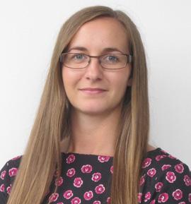
IN
SERVICE
42
TECHNICAL BOARD


Our first Technical Board meeting of 2022 was held on 1 February. Unfortunately, we were unable to go to Huddersfield University due to Covid but we were pleased to have a virtual presentation from Professor Yann Bevan. He explained the work of the Railway Research Centre and the substantial testing facilities for rolling stock and wheel-rail interaction. Of particular interest was the work on pantograph testing and the motion simulator. We look forward to seeing it in person at the July Technical Board.


We also had an insightful update from Nick Millington regarding a safety shut down on Network Rail High Output. This was a serious near miss involving a passenger train at Kettering. There were a number of issues including a risk assessment about crossing open lines but one which stood out was the vast amount of paperwork which needed to be understood. It was no surprise that some areas were missed. As Nick indicated this investigation was treated as thoroughly as if there had been actual injuries. Further responses and actions will be discussed at the next board.


Stephen Barber, CEO, PWI, gave a business and financial update on the PWI. Despite a tumultuous year, we returned a small profit in 2021. He also explained the next steps for the Practical Trackwork Challenges in March and October 2022.


Chris Mannion of Mott MacDonald gave us an excellent update on his company and its focus on technical design and system integration. The work on decarbonisation in Scotland was well advanced and he explained the Borders Rail project with its vision of greener, cheaper, faster in conjunction with Transport Scotland. The work on innovative OLE design included less carbon and less parts.

Joan Heery also updated us on the work of the Climate Change and Decarbonisation group and the seminar on 3 March 2022 in Manchester.


For
(kate.hatwell@thepwi.org) 43
Corporate
Members are fully involved in the development of the PWI, ensuring that our products and services meet the needs of the rail industry for technical expertise.
details of Corporate Membership please contect Kate
Hatwell PWI Operations Director
Seminar report
PLANT & MACHINERY
SUPPORT TO
RAIL INFRASTRUCTURE
RENEWAL AND MAINTENANCE FOR THE 2020s AND BEYOND
SAFETY COMES FIRST
NICK MILLINGTON - PRESIDENT, PWI SAFETY TASKFORCE LEADER - NETWORK RAIL
Nick explained (via video message) that plant is vital to the rail industry, particularly for increasing safety, by reducing the number of personnel required on-track.
INNOVATION IN PLANT
BOB BROWNING - HEAD OF CORPORATE STRATEGY QUATTRO PLANT
The first of the day’s presentations was by Quattro Plant’s Bob Browning, titled ‘Innovation and who is going to pay for it?’ Bob began by explaining that innovation is the practical implementation of ideas that result in the introduction of new goods or services, or an improvement in offering goods or services. He also said that Thomas Edison could be seen as being the father of innovation as in 1870 he famously innovated the electric light bulb rather than inventing it.
Quattro Plant is looking to innovate and find new clean propulsion technologies for its fleet of over 750 diesel-powered machines, a process it started five years ago.
Unfortunately, the last 12 months have seen a deterioration in safety levels on the railway with a number of injuries and even fatalities having occurred. Greater use of plant can assist in tackling this issue, but people and plant must still be kept apart.
Advances in the use of devices to monitor exclusion zones, and any incursions into them, is to be encouraged. Safety briefings also highlight the need to ensure that working with plant is kept safe at all times from depots to the worksite.

The company has partnered with the University of Exeter to look at the options available, as well as opening a research and development centre at its Newton Abbot Depot. So far, two road / rail machines have been converted to fully electric power - a John Deere Gator and a Neotec/Haulotte Skyrailer 160 MEWP - using technology developed by Quattro Plant and the University of Exeter.
After successfully completing trials with the two machines, it is now planned to convert further examples of both types including obtaining all the necessary approvals and certification. This will be undertaken in-house, as well as initial work to convert a road/rail tracked 360° excavator. Bob later explained that the company is also looking at the infrastructure aspects of supporting electric vehicles as the next phase of the project. This will cover the charging of vehicles, particularly on-site, and have some form of standardised plug arrangement.
CHAIRS AM: PHIL KIRKLAND - PWI VICE PRESIDENT NORTH-EAST | PM: JACK PENDLE - M&EE NETWORKING GROUP
TECHNICAL SEMINAR 24 NOVEMBER 2021 NEWCASTLE UPON TYNE
PWI
44
WATCH THIS SEMINAR IN THE KNOWLEDGE HUB, IT’LL COUNT TOWARDS YOUR CPD!

https://www.thepwi.org/knowledge/seminar-plant-machinery/

AUTOMATED TAMPING
BERNHARD ANTONY - HEAD OF TECHNOLOGY CENTRE PURKERSDORF, PLASSER & THEURER
Up next was Bernhard Antony from Plasser & Theurer with a presentation on the automation of the tamping process. As Bernhard explained, there have been four milestones in the development of on-track machines over the last 70 years, the first of which was the introduction of mechanised track maintenance. This was followed by the development of assembly line processes for tasks such as track renewals and ballast cleaning. The production of alternative hybrid and all-electric propulsion systems for machines was the third milestone, with the fourth being the digitalisation and automation of machine operation. For the latter, the development and introduction of smart tamping machines will reduce human intervention, with technology replacing the practical experience of operating staff.
OTMS ACROSS THE UK
MICHAEL ZEIDLER - HEAD OF PLANT MATT WHITING - SENIOR PROJECT MANAGER SWIETELSKY BABCOCK RAIL
Swietelsky Babcock (SB) Rail’s Michael Zeidler and Matt Whiting were next to take to the stage with a presentation titled, ‘Operating plant from the Channel Tunnel to Thurso’. They began by giving the background of the Joint Venture (JV), formed in 2004, that owns and operates On-Track Machines (OTMs) in the UK.
Typically, SB Rail now delivers over 3,500 OTM shifts per year through its framework agreement with Network Rail and has the youngest fleet in the UK. The JV has evolved, increasing its number of OTMs and sphere of operation. In 2011, it began working on High Speed 1 (HS1), utilising machines from Swietelsky Austria, and has now achieved over 10 years of operation on the route.
This will lead to less machine down time, increased efficiency, a better quality of output and fewer mistakes. Having undertaken a considerable amount of research and trial operations, Plasser & Theurer has been able to develop an automated system that will enable a tamping machine to undertake in-situ measurements of the track and ballast prior to any intervention.
It was found that clean ballast required less forces to be applied than dirty ballast, highlighting the need to treat them differently. The system can analyse the compaction effort required and also determine the ballast condition, before treating the track as required. Once completed, it is possible to provide a data log of the work undertaken including a visualisation of the area treated. There is also increased quality of the trackwork through dynamic compaction control, the ability to monitor the ballast condition and, therefore, predict the intervals required for cleaning.
Whilst tampers form the largest proportion of SB Rail’s fleet, it also includes ballast regulators, finishing machines and rail cranes. The organisation has always been at the forefront of new technology, having introduced many firsts to the UK like Kirow KRC250 UK cranes with rotator heads, track finishing machines and Plasser & Theurer 09-4x4/4S Dynamic tamping machines, with it now having six examples of the latter in its contract with Network Rail.
The JV started using biodegradable Panolin lubricants in machine hydraulic systems over 12 years ago, and in 2017 began replacing mineral oil in all major components with the equivalent Panolin product. Combined with regular sampling and analysis, this is providing considerable savings in waste oil and costs. Other environmental initiatives are also in place with regard to when a machine’s main engines are in operation in order to reduce emissions and save fuel. Looking to the future, SB Rail would like to see more of the UK rail network electrified, as this will enable the introduction of the hybrid electric OTMs, resulting in reduced emissions and fuel usage.
M&EE NETWORKING GROUP
JACK
PENDLE
- CHAIR, M&EE NETWORKING GROUP
MICK JAMES - DEPUTY CHAIR, M&EE NETWORKING GROUP
The M&EE Networking Group’s Chair, Jack Pendle, and Deputy Chair, Mick James, gave a presentation on the Group and its activities. Infrastructure Maintenance Units (IMUs) and Track Renewal Units (TRUs) were created in 1994 as part of privatisation of British Rail, later being offered for sale and becoming stand-alone companies as IMCs and TRCs.
A requirement of the Railway (Safety Case) Regulations was for the successor organisations to each have a professional Head of M&EE who became the controlling mind in respect of plant operations and M&EE. By forming a group of the newly-appointed heads, the philosophy of ‘a problem shared is a problem halved’ could ensue and the first M&EE Group meeting was held in 1994.
Through changes and mergers, the Group has continued with a strong commitment from its members to promote safe working practices with plant, help each other with reviewing incidents and accidents, and freely share knowledge to resolve problems.
Subsequently, the Group was also opened up to the operations side of the industry and now has 14 permanent member companies with over 25 attendees at each meeting. At first, no standards or procedures existed covering the operation of OTMs or On-Track Plant, so the Group produced its first Code of Practice (COP) in 1996. Today, 48 COPs have been produced, along with a series of safety posters, all available through the RSSB website.
Last year, the Group developed a memorandum of understanding with the Infrastructure Safety Liaison Group (ISLG) to work together to coordinate efforts. The need for an integrated plan for safety improvement was identified and this will be published shortly. A new sub-group has also been established to examine data on incidents / accidents involving plant, to understand the risks posed and determine priorities for further work. The overall aim being to identify trends and develop mitigations to prevent further incidents.
45
ELECTRIFICATION INNOVATION
OWEN MILLS - HEAD OF ENGINEERING, KELTBRAY RAIL
‘Plant innovation for electrification’ was the title of the presentation given by Keltbray Rail’s Owen Mills. In this talk, Owen detailed the way in which the company has come up with innovative ways of how to improve the use of plant during the installation of electrification.
He detailed the barriers to investing in innovation such as short contract durations, the time period before a return is made on the investment, the limited UK market and the time taken to achieve Network Rail Product Acceptance.
An industry change came in 2015 with the introduction by Network Rail of a modular OLE system, as used on the electrification of the Great Western Main Line. However, this actually resulted in
PROTECTION SYSTEMS
STEVE PINKNEY - PROGRAMME DELIVERY DIRECTOR XYZ RAIL AND CIVILS
Concluding the morning’s session was a presentation by XYZ Rail and Civils’ Steve Pinkney on the I-System high performance protection Any Line Open (ALO) system for off-track machines. Steve began by explaining what ALO working was and what the parameters of an exclusion zone would be against an open line in various track configurations. These were all as stated in the M&EE Networking Group COP for ALO working.
SITE SAFETY
larger and heavier equipment with an increased manual-handling challenge. There was also the need for the industry to ramp up for delivery projects, overcoming skill shortages, after the previous quiet period for electrification work.
Keltbray has responded by introducing a number of innovative plant solutions for the work. Examples Owen illustrated included road/rail lorry-based MEWPs being also equipped with a crane capability, a road/rail lorry-based wiring system with full tensioning, a means of installing high voltage cables safely, a road/rail excavator attachment for manipulating OLE masts and a rotational drilling head for OLE installation under bridges or in tunnels.
The company has also invested heavily in the training and development of staff for specific tasks and projects, which has delivered benefits on-site.
He then discussed the I-System equipment and how it could control machines that are working in the exclusion zone. It creates a virtual wall along a boundary line using I-Markers placed at three-metre intervals. The installed I-System recognises these markers and, through the Rated Capacity Indicator (RCI), cuts the machine’s power as it approaches the virtual wall, but also allows a safe movement away.
The system has the advantage that it can be easily and quickly moved to adapt to changing sites and situations. Three different versions of I-System are available, which can be fitted to any excavator, depending on the level of protection that is required.
DOMINIC
BALDWIN
- MANAGING DIRECTOR HASTEC RAIL
Dominic Baldwin from Hastec Rail gave a presentation on its Collision Avoidance System (CAS) and the Isolation Limit Control System (ILCS). In January 2020, working with its sister company Elmec Solutions, Hastec Rail commenced research and development into the CAS, the initial plan being to install it on Elmec’s road/rail hire fleet. Successful trials of the CAS were undertaken in December 2020 and the progress was presented to Network Rail.
As a result, in April 2021, Hastec Rail was commissioned to undertake trial installations of the CAS on some of Network Rail’s road/rail lorry-based MEWPs. The CAS is integrated into a machine’s control system and has a number of embedded, enhanced vehicular controls to limit both worksite and travel mode speeds.
INDUCTION WELDING
NICK MATTHEWS - HEAD OF TRANSFORMATION AND CONTINUOUS IMPROVEMENT, SOUTH RAIL SYSTEM ALLIANCE, NETWORK RAIL NICK
MOUNTFORD
- MANAGING DIRECTOR, MIRAGE RAIL
A joint presentation was given next by Network Rail’s Nick Matthews and Mirage Rail’s Nick Mountford titled ‘Induction welding and the experiences of breaking into the rail market’. Nick Matthews began by explaining that the objective had been to find a way of welding rail that was solid phase, but that did not have the waste area associated with flash-butt welding. It would need to have a bend strength close to that of an original piece of rail, minimal rail consumption for S&C installations and be delivered by a lightweight mobile-welding head, which could be deployed from various road/rail vehicles.
Its visual and non-visual system detects obstacles in the direction of travel, via an exclusion zone radar and camera monitoring system, with an audible cab alarm and warning lights. It is calibrated to function within W6 gauge and a safety-exclusion demarcation zone is visualised externally by a low magenta light. Once the vehicle engages in rail mode, a live and recorded video safety surveillance system is also activated.
The CAS has received Network Rail Product Acceptance for the current machines with other types imminent. Reminder of Live Exposed (RoLE) equipment provides a means of identifying the safe working limits on-site, as detailed on an overhead line permit. The CAS has been enhanced to enable the ILCS to be an integral part for a machine fitted with a transmitter system to detect RoLE equipment. On detection, the operator receives an audible notification and a visible warning that they are approaching the isolation limits, with the vehicle then brought to a controlled stop.
The system is currently in advanced development with a number of site trials having been conducted.
Nick explained, following various bench tests, prototype weld heads were developed and trialled, resulting in a production prototype. This has met the objectives with a less than seven-minute weld process time, but some difficulties have been encountered. The Covid-19 pandemic has also not helped for undertaking further trials and staff availability, but it is hoped to build a second prototype head incorporating the lessons learnt.
Nick Mountford then took over to explain the challenges Mirage Rail has encountered in breaking into rail, with the company’s background in the automotive, food and pharmaceutical production equipment markets. He reflected on the various costs associated with entering the rail market for certifications and organisation memberships, in addition to the actual development costs for the technology which was funded by Network Rail. He would like to see some simplification of the processes and systems in order to encourage greater innovation.
46
QUICKER RAIL WELDING
MICHAEL COWAN - MANAGING DIRECTOR GOLDSCHMIDT SMART RAIL SOLUTIONS

Continuing on the welding theme, Michael Cowan from Goldschmidt Smart Rail Solutions was next to give a presentation, on the Smartweld Advanced Cooling Equipment (ACE).
The Smartweld ACE is a purpose-designed cooling unit used to minimise the time taken to produce an aluminothermic weld in rail. It achieves this through the direct application of a fine water mist spray on to the sheared weld surfaces.
When an aluminothermic weld is cast, the temperature is around 1,400°C. Grinding of the weld cannot take place until the temperature has cooled below 400°C, which can take approximately
DTS TECHNOLOGY
CHRIS CHRISTIANSEN - TECHNICAL ENGINEER, PLASSER UK
Returning to OTMs, Plasser UK’s Chris Christiansen gave a presentation titled ‘Dynamic Track Stabiliser (DTS) the latest technology in the forefront of maintenance and renewal’. Chris began by detailing the OTM types with DTS equipment fitted that are available in the UK.
DTS technology has had many trials and papers written about it over more then 40 years, being probably the most investigated machine
AUTOMATING TRACK MAINTENANCE
MICHAEL REITER - TECHNICAL ENGINEER, ROBEL
The final presentation of the day was ‘Seizing opportunities for automated track maintenance’ by Michael Reiter of Robel. He started by saying there were five reasons that moved Robel to develop automated rail maintenance solutions. They were:
• A bottleneck of well-trained core staff, which was compromising business results.
• Track maintenance windows are getting shorter and work is carried out during stressful night shifts, so safety has to be paramount.
• Jobs have to be done right the first time, in full control and must meet rising quality standards.
• Emissions in railway maintenance have to be reduced to protect staff and the environment.
• The total cost of ownership has to decrease, so return on investments can be shortened.
CLOSING REMARKS
Alex
30 minutes by natural cooling. Hot grinding of a joint can lead to depressions or dips in the head of the rail when it has fully cooled.
The Smartweld ACE reduces the cooling time through the application of a fine water mist. However, it is important to carefully control the rate of cooling of the weld as too high a rate will cause the formation of martensite within the weld, which will weaken it and potentially lead to failure.
The equipment comprises a controller and two application heads, one for standard welds and another for head repair welds, and is certified and approved for use on both Network Rail and TfL infrastructure. Michael then went through the weld processes and the timings, along with the savings that could be made, using Smartweld ACE.
Plasser & Theurer has ever built, with research still ongoing. He went on to explain how DTS works, on both plain line and S&C, and the different types of DTS units - fixed and imbalance.
The latter can be found on the very latest Plasser & Theurer 09-4x4/4S Dynamic tampers operated by Colas Rail UK and SB Rail. It has been found that by adjusting the variable aspects of DTS operations - frequency, imbalance, the vertical load and the machine speed - optimum results can be achieved for the settlement of ballast. Chris later referenced the work by Network Rail’s Graham Penfold on the use of DTS for maintenance activities and the success it has achieved.
Robel’s approach to answer these is to deliver resource-saving, reliable and safe automated track maintenance solutions. The company is doing this by using proven, flexible manipulators, such as robots, into which industrial PLC systems solutions are applied. Industrial standard BUS systems and protocols are used for ease of integration, along with standard toolings and connectors. The area of automated rail defect repair is Robel’s first aim to show the feasibility of the technology. This covers defect detection, defect removal, heating, welding, finishing and documentation.
Michael then detailed how the six stages of the process work and the technology involved. Robel’s robotics platform is a flexible solution to varying tasks on-track, which comprises two robots, all within a standard 40’ ISO container with hybrid power that combines diesel and battery technology.
Michael concluded by saying that the development in technology had been achieved by seven people in the company, in just two years, which was a remarkable achievement.
The day was brought to a conclusion by Stephen Barber, Chief Executive, PWI. He thanked Phil and Jack for chairing the morning and afternoon sessions, as well as the speakers for their presentations. Stephen commented that some of the key aspects that could be taken away from the day’s proceedings were safety, electrification and electric power for plant, which all sit with the emissions challenges that are on the horizon and the potential modal shift changes in the use of rail.
HALL
STEPHEN BARBER CEO, PWI
AUTHOR: ALEX
47
is the Production Manager for Rail Infrastructure magazine. He started a career in railway publishing in 1994 and, in 1998, joined his now colleague, Roger Butcher’s company, NPT Publishing, to establish Rail Infrastructure magazine. As well as undertaking the design, production and some editorial compilation of the publication, Alex has also been extensively involved in producing the series of reference books on railway plant and equipment by NPT publishing, the latest of which – On-Track Plant 11th Edition – was recently published.
THE PWI’s COMMITMENT TO BUILDING A DIVERSE, INCLUSIVE, OPEN COMMUNITY.
Diversity is about understanding and recognising that we all have different backgrounds, life experiences, and beliefs. Inclusion means everyone is involved and treated fairly. Supporting diversity and inclusion is about developing a sense of belonging, and valuing people for who they are.

Over the past few years, the rail industry has worked hard to improve diversity and inclusion within the sector, to establish a more diverse workforce, and to foster an inclusive culture. As a community for rail infrastructure engineers, the PWI is a fantastic network of railway engineering knowledge, skill, and experience. The Institution is committed to ensuring its community is representative of the diversity within the wider rail industry workforce. So, we are developing a fully intersectional approach to diversity and inclusion, recognising that markers of diversity do not exist independently of each other. Our approach will include retaining data on more protected characteristics to allow for a greater understanding of different experiences within our membership.
Before the Covid-19 pandemic the PWI increased engagement with young workers in the railway engineering sector. Gender diversity within the Institution had also improved on previous years with 23% female representation on the Board. Amongst the PWI’s professional registrants 10% identify as women, slightly greater than the average across all engineering institutions, and a position the Institution is focused on improving.
The Institution is on a voyage of transformation. As part of this journey, the PWI has adopted the Royal Academy of Engineering (RAEng) Progression Framework for Professional Engineering Institutions, which it will use to monitor its progress. Providing a platform for rail infrastructure engineers from underrepresented groups is key to embracing and celebrating the diverse talent within the PWI community and beyond, and to achieve this aim the Institution has committed to the Diverse Panels pledge.
To allow our community to recognise and remove any hidden biases within our Institution, the PWI is rolling out unconscious bias training, starting with members of its main committees and the executive team.
Strengthening diversity and removing barriers within our community is in everyone’s interest. This year, the PWI established an Advisory Committee on Diversity and Inclusion chaired by PWI Past President John Edgley. The Committee will identify issues, gather and evaluate information, and recommend courses of action to better integrate diversity and inclusion within the culture of the Institution.
A priority for the Committee is to set out a more formal D&I policy and strengthen the PWI’s plans to promote equality so that we play our full part in enacting positive change within our community and across the wider industry.
As an LGBTQ+ person, I have worked both in environments that have been welcoming and some that have been less so. Since I began working for the PWI in July 2021, my experience has fallen firmly into the former category, and I am thrilled to have joined the executive team at a time when diversity and inclusion is on the agenda. I’m already enjoying promoting and celebrating the diversity of voices and talent within the PWI community and highlighting the Institution’s commitment to supporting rail professionals belonging to underrepresented groups. To work for an organisation, where I can be myself, share ideas, and feel like my voice matters is a powerful thing, even more so - anecdotally at least - when one isn’t a stranger to the impact of everyday prejudices.
Choosing to ignore underrepresentation would mean missing out on a wealth of talent, knowledge, and experience. Women make up 51% of the UK population but only 16% of the UK rail industry’s workforce. Those from black, Asian and minority ethnic backgrounds make up 14% of the general population and only 6% of the workforce. By committing to and encouraging diversity and inclusion, we can build a stronger community and a stronger Institution.
Luke Goude MARKETING EXECUTIVE marketing@thepwi.org

48
FItted
Tighten and loosen all types of screwed fasteners and drill holes in Wooden Sleepers. Can be mounted onto existing and new Master Tool Carriers.

New Improved version. Ideal for the following :

• Switch tip alignment
• Track Slewing
• Switch Positioning Crossing Nose Alignment
•
Replacing Insulated Joint End Posts.
Adjusting gap on jointed track, Switches and Crossings and to correct for creep movement.


Replacing broken and worn fishplates using Master 35® Impact Wrench.

Adjusting breather switches utilising nearest fishplate joint.
Will remove the toughest of frozen/rusty Clips.
Use on outside track and inside the MMT in conjunction with Floating Trolley

Fastclip Remover
Will install and remove Clips quickly using our quick change Jaws
Battery, Diesel & Petrol Trackpack

Master 35® Impact Wrench & Tool Carrier NEW Lase Align Melvelle E Clip Remover Rail Gap Adjuster
40 Couper Street, Glasgow, G4 0DL T: 0141 552 5591 F: 0141 552 5064 E: enquiries@maximpower.co.uk W: www.maximpower.co.uk NEW
with a more powerful LOW EMISSION EUR5 compliant engine. Faster, lighter weight and LOWER VIBRATION EXPOSURE
49
Rail Dip Measurement T R A C K M A I N T E N A N C E E Q U I P M E N T
Great things are here

The new PWI website is live online and we cannot contain our excitement! The central team spent the last few months beavering away and now this new and improved digital home is ready for you to explore.


You will find all the usual important stuff about your membership, plus information on events, training, professional registration and more – only now on a fresh and easy-to-use website powered by a far greater user interface and content management system. Log into your member portal to track your Continued Professional Development, benefit from discounts, and book your place on training courses and events. Plus, access hundreds of technical resources in our new Knowledge Hub.
We hope you enjoy the new look and feel, which is aligned to our brand enhancement, and that all these changes show our continued commitment to providing the best services and experiences to our valued community.

50
...
CPD (Continuing Professional Development) refers to the learning you do to develop or maintain the knowledge and skills you need to succeed in your career and maintain your professional competency. The most important thing is to focus on its relevance to your current role and your future career ambitions.
CPD demonstrates your competence as you keep yourself up to date. It instills self-confidence, and inspires confidence in those who work with you. And by demonstrating your commitment to learning, you are more likely to be given opportunities to progress in your career.

REMEMBER TO LOG WHAT YOU WATCH, READ, & LISTEN TO, FOR YOUR CPD.
What is CPD?
is CPD
important?
Why
so
When should I do CPD? Don’t leave it until the last minute! You should plan your CPD activity at the start of the year to ensure it is relevant to your development needs. Log it online with MyCPD MyCPD is the online tool to assist you in your career planning and help you demonstrate your professional competency. MyCPD is available to all PWI members. USE THE PWI KNOWLEDGE HUB FOR CPDYOUR 51
AGM Agenda
Friday 8 July 2022
16:00 - 17:30
Macdonald Burlington Hotel Birmingham B2 4JQ
The full agenda and accompanying papers will be published on the website in May 2022 www.thepwi.org
1. To receive apologies for absence.
2. To celebrate the lives of members who passed away during 2021.
3. To receive the roll call of the Sections.
4. To receive and agree the minutes of the 2021 Annual General Meeting, held on Friday 2 July at 16.00hrs at the MacDonald Burlington Hotel, Birmingham.
5. To receive a report from the President.
6. To receive a report from the Chief Executive Officer.

7. To receive and adopt the Directors’ Report and Accounts for the year ending 31 December 2021.
8. To confirm Peter Dearman as President.
9. To elect officers of the Institution.
Any member wishing to propose a candidate for any of the above posts must advise the Secretary in writing not less than 28 clear days in advance of the Annual General Meeting. Any candidate must meet the requirements of Clause 4(1) of the Articles of Association. Details of the person specification for each role are available from the Secretary.
A member entitled to attend and vote at the meeting, but who is not able to attend, is entitled to appoint a proxy to vote in his/her place. Proxy forms will be available on the PWI website or can be obtained from the Secretary and must be returned not less than 7 clear days in advance of the Annual General Meeting.
To increase the accessibility of the Annual General Meeting, and to mitigate against government restrictions that would prevent the meeting from taking place in a face-to-face environment, this year’s AGM will also be streamed online. Any member joining virtually will have the opportunity to listen to the presentations and ask questions in real time. Voting online will not be possible and members joining the meeting virtually and wishing to vote must signify their voting intentions in advance via the submission of a proxy form. Full details of how to register to attend and vote by proxy will be published on the PWI website in May 2022.
2021 Accounts
The full version of the 2021 accounts is available. Please visit the PWI website, or contact the Membership Team: secretary@thepwi.org
Permanent Way Institution (Incorporated) Company Limited by Guarantee Directors' Report
Year ended 31 December 2021
The directors present their report and the financial statements of the company for the year ended 31 December 2021.
Directors
The

Ms M Nolan - McSweeney
Mr S J Bell (Appointed 2 July 2021)
Prof W Powrie (Appointed 2 July 2021)
Mr J C Dutton (Resigned 2 July 2021)
Mr J G Edwards (Resigned 2 July 2021)
directors who served the company during the year were as follows: Mr A J Cooper Mr S B Whitmore Dr B J Counter Mr S J Barber Mrs K J Hatwell Miss J Heery Mr A Tappen Mr N J Millington Mr J R Edgley Mr P Dearman
52
Permanent Way Institution (Incorporated)

Company Limited by Guarantee Directors' Report (continued) Year ended 31 December 2021

2021 Accounts
Other matters
This statement complements the quarterly updates from the President and the CEO provided in each PWI Journal. PWI operations in the early part of 2021 followed the successful pattern established in 2020. As the year progressed the Institution was able to increase the level of face-to-face interaction, returning to a more normal activity profile, albeit still subject to disruption caused by restrictions imposed due to the continuing coronavirus pandemic. Whilst 2021's problems were not on the epic scale of those faced in 2020, the ramping up of activity against a background of sequential loosening and tightening of government restrictions meant the year presented its own particular set of challenges.

The Institution delivered a turnover level 14.1% up on 2019's last 'normal' trading year and 23.1% up on 2020's corresponding total. A 2021 profit margin of 0.9% resulted in members' funds increasing by 4.9% in the year. On 31st December 2021 we were supported by 3,480 Personal Members, representing 3.6% growth on 2020, and 56 Corporate Members, a small increase on 2020. We continue to see growth in our professionally registered membership which stood at 250 at the year end. During 2021 the Board of Directors met four times. Three of these meetings were held using an online platform and one was held face-to-face, establishing a pattern for the future. The July AGM reverted to face-to-face format and members were offered an option for online attendance. 101 section meetings were held in 2021, the majority of which were online, though 8 Sections resumed face-to face meetings towards the end of the year. Online and face-to-face PWI training courses registered total attendance of 412 in 2021, up by 52% on 2020 and by 37% on 2019's last normal trading year figure of 300. The PWI further grew its use of the internet and online applications in the day-to-day management of its business, though supplier issues pushed implementation of its new website, knowledge hub, and more integrated email system back into 2022. Work continues to better integrate the Institution's strong commitment to diversity and inclusion into its operating practices, so that the PWI can be confident that it remains welcoming and attentive to all. The Institution's Climate Change Adaptation and Decarbonisation committee has taken a leading role helping the Board to set relevant PWI policy. In 2021, the PWI quantified its carbon footprint in accordance with ISO-14064-1:2006 and the Greenhouse Gas (GHG) Protocol, and, through a certified offsetting scheme, became carbon-neutral. In 2021 the Institution again expanded its own in-career technical education and training activity, as well as progressing its initiatives on career development; workforce safety; and codifying technical competence. Notably, the year saw the launch of the Institution's diploma in electrification engineering, marking a further widening of the support it offers to those engaged in railway electrification work. Consolidating its presence in the sphere of engineering education, the PWI joined the Joint Board of Moderators: a group of five professional engineering institutions responsible for assessing and approving educational programmes related to the built environment.
Looking forward, the Institution intends to use the greater freedom for face-to-face interaction promised for 2022 to reinstate and expand the PWI's range of social, as well as technical and educational activities. The Board routinely monitors the risks and opportunities facing the Institution and, as we look to 2022 and beyond, we are conscious that the UK's railway transport industry faces an unprecedented set of economic, environmental, and political challengesand opportunities. As an integral part of the railway industry, the PWI's mission is to help its membership, personal and corporate, develop to meet such challenges, and equip themselves to deliver the modern, efficient, and low-carbon integrated transport systems that all modern societies require. We look forward to harnessing the focussed efforts of our Executive team and the continued support of an enthusiastic membership to fulfil that mission.

3
-
-
53
(Incorporated)
Permanent Way Institution
Company Limited by Guarantee Independent Auditor's Report to the Members of Permanent Way Institution (Incorporated) (continued) Year ended 31 December 2021
2021 Accounts
Permanent Way Institution (Incorporated)
Company Limited by Guarantee
Independent Auditor's Report to the Members of Permanent Way Institution (Incorporated)
Year ended 31 December 2021
Other information
The other information comprises the information included in the annual report, other than the financial statements and our auditor’s report thereon. The directors are responsible for the other information. Our opinion on the financial statements does not cover the other information and, except to the extent otherwise explicitly stated in our report, we do not express any form of assurance conclusion thereon. In connection with our audit of the financial statements, our responsibility is to read the other information and, in doing so, consider whether the other information is materially inconsistent with the financial statements or our knowledge obtained in the audit or otherwise appears to be materially misstated. If we identify such material inconsistencies or apparent material misstatements, we are required to determine whether there is a material misstatement in the financial statements or a material misstatement of the other information. If, based on the work we have performed, we conclude that there is a material misstatement of this other information, we are required to report that fact. We have nothing to report in this regard.
Opinions on other matters prescribed by the Companies Act 2006 In our opinion, based on the work undertaken in the course of the audit:
the information given in the directors' report for the financial year for which the financial statements are prepared is consistent with the financial statements; and
the directors' report has been prepared in accordance with applicable legal requirements. Matters on which we are required to report by exception In the light of the knowledge and understanding of the company and its environment obtained in the course of the audit, we have not identified material misstatements in the directors' report. We have nothing to report in respect of the following matters in relation to which the Companies Act 2006 requires us to report to you if, in our opinion:
adequate accounting records have not been kept, or returns adequate for our audit have not been received from branches not visited by us; or
the financial statements are not in agreement with the accounting records and returns; or
certain disclosures of directors' remuneration specified by law are not made; or
the directors were not entitled to prepare the financial statements in accordance with the small companies regime and take advantage of the small companies' exemptions in preparing the directors' report and from the requirement to prepare a strategic report.6 -
we have not received all the information and explanations we require for our audit; or

Opinion We have audited the financial statements of Permanent Way Institution (Incorporated) (the 'company') for the year ended 31 December 2021 which comprise the statement of comprehensive income, statement of financial position, statement of changes in equity and the related notes, including a summary of significant accounting policies. The financial reporting framework that has been applied in their preparation is applicable law and United Kingdom Accounting Standards, including FRS 102 The Financial Reporting Standard applicable in the UK and Republic of Ireland (United Kingdom Generally Accepted Accounting Practice).
In our opinion the financial statements:
give a true and fair view of the state of the company's affairs as at 31 December 2021 and of its profit for the year then ended;
have been properly prepared in accordance with United Kingdom Generally Accepted Accounting Practice;
have been prepared in accordance with the requirements of the Companies Act 2006.
Basis for opinion We conducted our audit in accordance with International Standards on Auditing (UK) (ISAs (UK)) and applicable law. Our responsibilities under those standards are further described in the auditor's responsibilities for the audit of the financial statements section of our report. We are independent of the company in accordance with the ethical requirements that are relevant to our audit of the financial statements in the UK, including the FRC’s Ethical Standard, and we have fulfilled our other ethical responsibilities in accordance with these requirements. We believe that the audit evidence we have obtained is sufficient and appropriate to provide a basis for our opinion.
Conclusions relating to going concern
In auditing the financial statements, we have concluded that the directors' use of the going concern basis of accounting in the preparation of the financial statements is appropriate.
Based on the work we have performed, we have not identified any material uncertainties relating to events or conditions that, individually or collectively, may cast significant doubt on the company's ability to continue as a going concern for a period of at least twelve months from when the financial statements are authorised for issue. Our responsibilities and the responsibilities of the directors with respect to going concern are described in the relevant sections of this report.
5 -
54
Permanent Way Institution (Incorporated) Company Limited by Guarantee Statement of Comprehensive Income Year ended 31 December 2021
2021 Accounts
£
2021
£
2020 Note
777,804
Turnover
631,609 Cost of sales
408,947
315,060
462,744
222,662 Gross profit
455,641
Administrative expenses
408,915 Operating profit
7,103
32 Income from other fixed asset investments
4,987
1,657 Other interest receivable and similar income
945
4,505 Profit before taxation
713,035
6,194 Tax on profit
1,051
1,093 Profit for the financial year and total comprehensive income
5,101 All the activities of the company are from continuing operations.
11,984
The notes on pages 11 to 17 form part of these financial statements.8 -

55
Profit and loss account
Permanent Way Institution (Incorporated) Company Limited by Guarantee Statement of Changes in Equity Year ended 31 December 2021 Fair value reserve
2021 Accounts
£
Total ££
48,909164,253213,162
At 1 January 2020
1,007(1,007)–
1,0074,0945,101
218,263
Profit for the year
5,1015,101 Other comprehensive income for the year: Reclassification from revaluation reserve to profit and loss account
Total comprehensive income for the year
49,916168,347
At 31 December 2020
11,984
11,984
230,247
Profit for the year
11,984 Other comprehensive income for the year: Reclassification from revaluation reserve to profit and loss account
3,7168,268
3,716(3,716) Total comprehensive income for the year
53,632176,615
At 31 December 2021
The notes on pages 11 to 17 form part of these financial statements.10 -

56

THE PWI LUNCH & LEARN PROGRAMME WELCOMES A SERIES OF PRESENTATIONS FROM INDUSTRY EXPERTS WHO WILL OFFER YOU A UNIQUE INSIGHT INTO DIFFERENT ASPECTS OF THE RAIL SECTOR. PWI LUNCH & LEARNS For PWI members and beyond, the PWI Lunch & Learn programme is a fantastic continuing professional development opportunity. During the one-hour online sessions, you will hear about the latest topics, key projects, and innovations in the rail industry. You’ll also have the chance to put your questions to speakers in a Q&A at the end of each session. Managing Risks from Railway Earthworks Tuesday 26 April Northumberland Part 1 Tuesday 10 May Northumberland Part 2 Tuesday 17 May Electrification of the Cardiff Valleys Tuesday 24 May Dry Ice for Cleaning Railhead Tuesday 7 June Challenges of Maintaining a High Speed Railway Tuesday 28 June Nine Elms Junction Tuesday 12 July Outputs from In2TRACK2 Tuesday 19 July 57
over


d equipment specifically used for working on, or assisting in, the maintenance and r enewal of the railway infrastr uctur e in Gr eat Britain. It is a har dback, 360 page, full colour thr oughout, thr ead sewn publication with extensive colour illustrations. Included within it ar e compr ehensive details of:

s
r
■ On
■ Road/rail
■ Small
■ Owner
■ Manufacturer
On Track Plant 11th Edition can be obtained from Book Law Publications Copies cost £40.00 each - plus postage and packing. To obtain your copy, with secure online or dering, please visit: www.booklaw.co.uk Or ders can also be placed by telephone on: 0115 961 1066 Or by post from: Book Law Publications, 382 Carlton Hill, Carlton, Nottingham, NG4 1JA
of On- Track Pl ant - 11th Edition How to or der: 58
in the series of books first published
35 years ago. It is the definitive guide t o r a i l - m o u n t e d a n d
e l f - p
o p e l l e
track machines.
vehicles.
plant.
listings.
details.
Publishers


¬ suitable for most rail and sleeper types ¬ Network Rail Approved up to 70mph Linespeed ¬ can be combined with all STRAIL inner panel systems ¬ popular areas of application: inner city, e.g. in front of schools, day-care centres, shopping centres, in front of hazardous crossing angles, e.g. for cyclists and wheelchair users, baby carriages, inlineskaters, trolley bags, etc. the safe system with compressible flange groove. STRAIL (UK) Ltd. - Richard Whatley | Tannery Lane // Send / Woking // GU23 7EF // Great Britain Phone +44 (14 83) 22 20 90 // info@strail.com // www.strail.com THE FLANGEWAYLESS INNER PANEL SYSTEM. @strail_official @kraiburg strail simply safe > typical veloSTRAIL 59
TRAINING UPDATE

We have started 2022 with a packed programme of PWI training and our team have been extremely busy with over 150 people taking part and achieving a 96% pass rate. We got some great feedback about our enthusiastic and experienced trainers and the delivery process both virtual and face to face in Derby and Milton Keynes. You can now see the trainer’s biographies on the new website, and I would encourage you to contact us if you have a question. Full details of our courses are on the website.
It was great to see the launch of our Module 2 for Electrification in January and Module 3 is taking place this month. Network Rail have endorsed the PWI Electrification Engineering Diploma as a key component for their Electrification and Plant graduate training programme.
Going forward, we are looking to develop training for supervisory and technical staff to fill the gap between Apprentice Level 3 and the PWI Diploma Level 6. This will include surveying, maintenance and renewal design, maintenance methodologies and use of machinery. The theory and practice of track quality and rail management will also to be included.
I always encourage trainees to progress towards professional status in electrification and track, and training is invaluable in gaining confidence to pass these professional reviews. There is great esteem by being a registered engineer and having letters after your name. I would go so far as to say it is particularly career enhancing. I have had a number of calls from people who thank me and say they got their promotion because of PWI training and registration.
TECHNICAL DIRECTOR - PWI technicaldirector@thepwi.org
INDUSTRY REVERED, FIRST CLASS TRAINING
IN-PERSON OR ONLINE THROUGH OUR VIRTUAL CLASSROOM, ACCESS FIRST CLASS TECHNICAL TRAINING, DEVELOPED AND DELIVERED BY EXPERIENCED RAIL INFRASTRUCTURE ENGINEERS. I RECENTLY COMPLETED MODULE 2 OF THE ELECTRIFICATION ENGINEERING DIPLOMA. I’D JUST LIKE TO SAY I REALLY ENJOYED THE COURSE, THE CONTENT WAS REALLY GOOD AND I FELT I LEARNT SO MUCH DURING THE WEEK. I CAN’T WAIT TO SEE MY RESULT, AND I CAN’T WAIT TO COMPLETE MODULE 3. Daniel Heath-Holmes EngTech, TMIET, MPWI Senior Technical Officer, E&P Works Delivery, Network Rail TRACK ENGINEERING DIPLOMA S&C REFURBISHMENT ELECTRIFICATION ENGINEERING BESPOKE TRAINING
WHETHER
60
PWI ELECTRIFICATION ENGINEERING
PWI
COURSE
The aim of the programme is to give delegates an understanding of the principles of the theory and practice of electrification engineering in the UK.
The trainers are all very experienced electrification engineers who have spent their careers designing, constructing, operating and maintaining systems in the UK and abroad.
This course is comprised of three consecutive modules involving 100 hours of taught study all mapped to HE Level 6. Upon successful completion of all three modular assessments, candidates will be awarded the PWI Diploma in Electrification Engineering. Further development of supplementary modules will take place late next year to include 3rd/4th rail and side contact systems alongside power and distribution.
These courses are aimed at newly qualified and experienced engineers and will give delegates the knowledge and skills needed for professionals in electrification engineering.
Course dates run from Monday to Thursday
MODULE 1: SYSTEMS AND MAINTENANCE
16 – 19 May 2022
Derby
Gives delegates a knowledge of OLE system types and the interfaces with the pantograph. Provides an understanding of the essential interfaces with other rail infrastructure including earthworks, structures and clearances. Develops knowledge of inspection, maintenance, servicing and repair processes. Gives an understanding of the concept of the UK rail system, operations, timetables, and legislation.
MODULE 2: DESIGN
18 – 21 July 2022
Derby
Focuses upon electrification design for projects and enhancements. Gives an understand design categories and processes. Develops skills in design of electrical, mechanical and civil engineering aspects including construction design and bonding design. Includes design case studies and exercises.
MODULE 3: ADVANCED ASSET ENGINEERING, CONSTRUCTION AND RENEWALS
25 - 28 April 2022 / 7 – 10 November 2022
I gained a huge amount of insight during the practical and now feel more confident around S&C. I would highly recommend this course especially if you want to gain knowledge of S&C to a high level from very knowledgeable people.
PWI TRACK ENGINEERING DIPLOMA
Derby
The study becomes more strategic and delivery oriented with advanced asset management techniques and applications. Gain a deep understanding of UK OLE construction and renewal processes including commissioning, OLE system testing and handback to service. Provides an understanding of ethical and sustainability aspects of OLE work and future proofing for climate change.
Course cost: £645 Accommodation cost: £245 See www.thepwi.org for full details
I learned aspects of OLE that I have never come across in my OLE career; this will benefit me in the future.
ENGINEERING AND RENEWALS
I found the three modules thoroughly enjoyable and valuable in developing my understanding of railway maintenance and its interdependencies. Thank you for putting together a brilliant course which was well presented. I am now interested in becoming an Incorporated Engineer.
S&C
24 - 28 October 2022 / 20 - 24 February 2023 All Derby Delegates on this course will gain comprehensive detailed knowledge of S&C and how to undertake refurbishment safely, efficiently and to the required engineering quality.
will cover both the track assemblies and the trackbed
S&C. Participants will undertake detailed analysis and inspection
layouts
and specify work correctly to provide the
life
will then ensure that delegates understand the
maintenance interventions
and its components and can plan
Components Design
Analysis
Delegates will have to pass a formal assessment
will be awarded a PWI Certificate in S&C
on successful completion. Course cost: £895 Accommodation cost: £325 See
for full details
REFURBISHMENT TRAINING COURSE
The course
under
of
so that they can scope
necessary
extension of the layout. The course
various
suitable for S&C
those required in the correct sequence. Modules include: S&C
and
/ Site Survey and Measurement / Scoping and Planning.
at the end of the course and
Refurbishment
www.thepwi.org
The aim of the programme is to give delegates an understanding of the principles, theory and practice of track engineering in the UK. It is comprised of three modules and involves 100 hours of taught study all mapped to HE Level 6. Upon successful completion of all three modular assessments, candidates will be awarded the PWI Diploma in Track Engineering. This course is aimed both at newly qualified and experienced engineers, and will give delegates the knowledge and skills needed for professionals in track engineering. MODULE 1: TRACK MAINTENANCE 23 - 26 May 2022 Derby / 12 - 15 September 2022 Virtual Classroom / 14 - 17 November 2022 Derby / 6 - 9 February 2023 Virtual Classroom Gives a basic understanding of track engineering and its theory and context. Develops a knowledge of track types and features, its interfaces with other rail infrastructure including earthworks, structures and clearances, and track maintenance including ballast, drainage, stressing, grinding and welding. MODULE 2: TRACK DESIGN 18 - 21 July 2022 Derby / 31 Oct- 3 Nov 2022 Virtual Classroom / 16 - 19
January 2023 Derby Focuses upon track design for projects and enhancements. Through design case studies and exercises, develop skills in track design of plain line and switches and crossings, component knowledge and configurations, layouts, innovations and life extension, route evaluation and trackbed design.
track renewal planning,
methods,
renewal scenarios
management issues,
strategic
MODULE 3: ADVANCED TRACK ASSET
9 - 12 May 2022 Virtual Classroom / 26 - 29 September 2022 Derby / 5 - 8 December 2022 Virtual Classroom / 6 - 9 March 2023 Derby The study becomes more strategic and delivery oriented with advanced asset management techniques and applications. Gain a deep understanding of UK
plain line, S&C, existing and future
rail
and optioneering, and learning from accidents. Understand advanced technical rail
rail sustainability and
track asset management.
qualification to
for
Foundation Degree
Module cost: £645 (Virtual or Derby) Accommodation cost: £245 See www.thepwi.org for full details Top-up
IEng
HND /
Holders
Chris Fuller Network Rail
Jacob Fay Network Rail
61
Stephen Bamford Story Contracting
NEW MEMBERS
We’re honoured to have you on board and are thoroughly looking forward to working with you. We’ll keep you updated on news and events via our monthly newsletter as we don’t want you to miss a thing. We have a thriving social media network and we’d love to see you get involved! We’re here to help, so if you have any questions, then shout out!
Bengaluru: Roshan Pradhan, Sharib Ashraf. Birmingham: Michael Cook, Khaled Idris, Kemal Toraman, Sakdirat Kaewunruen, Benjamin Racsa, Andrew Foster, Steve Williams, Dave Thawley, Arpyit Gupta, Dhruv Joshi, Tim Flower, Juan Manuel Perez Nieto. Cheshire & North Wales: Paul Wilde, Javaid Jat, Sam Snelson, Ryan Phillips, Simon Bennett. Croydon & Brighton: Emmanuel Asare. Edinburgh: Douglas Craig. Exeter: Matthew Liddle. Glasgow: Joseph Dunleavy, Alistair Gray, Howard Jones. International: Nathan Atkins, Sihle Makore, Mohamad Torkman, Mohd Afiq Amsyar Arifin, Muhammed Jaleel, Tanka Prasad Chettri, Wilbard Nashima, Charlie Muller, Lisa Allsopp. Irish: Simon Webber, Ciara Doherty, Kathy Kissane, Hal Nordmann, Darryl Gwilliam. Lancaster, Barrow & Carlisle: Andrew Greenwood, Terry Brown. London: Audrey Ghislaine Bouobda Lienou, Jenkins Entee, Thomas Riding, Anthony Van-Ackeren, David Rogerson, Kees Vanamolder, Miracle Michaelmbata, Keith Adams, Kristina Mansi, Edward Hill, David Smith, Frank Reilly, Henry Wright, Callum Patten, Clarke Arthur, Niamkey Aman Victor Ezani, Richard Famadewa, Maahir Subhani, James Lock, Joseph Gibson, Mark Jolly, Hamidah Nansasi, Alvin Brown, Lewis Heath, Dave Story, Kondwani Gondwe, Jordan Roane, Patrick Neary, Stuart Burrows, Andrew Vine, Peter Davie, Mullai Kody Sathiyanarayanan. Manchester & Liverpool: Richard Hellings, Jonathon Cooke, Dave Armstrong, Johan Strydom, Adam Gallimore, Michal Aniol, Helen Johnson, Josef Morgan-Griffiths, Vijay Chilla, Matthew Grace, Lewis Thompson, Monique Brindley. Milton Keynes: Matt Knill, Ruth Thomas, Darren Coulson. North East: Alex Gibson, Andrew Parker, George Cowie, Aodhan Horsman, Tom Briggs, Harry Kernohan, Stephen Wright, Weardale Railway, Barry Gibson, Calvin Breakwell. Nottingham & Derby: Charlotte Hill, Dominic Meakin, Phil Dreuitt, Ahmad Mohammadi, Hayden Cave, Richard Hill, Pete Lindley. Wessex: Rodrigo Rampas, Robert Whitehead. West of England: West Somerset Railway, Malcolm Short. West Yorkshire: David Lucas. York: Craig Kirkwood, James Swatman, Iain Green, Srinivasa Rao Mulakala, Ben Hamilton.
FELLOWSHIPS
Simon Warren – West of England
Mervyn McCollam – Irish
Peter Alford – Ashford
Richard Marsh – Manchester & Liverpool
PROFESSIONAL TITLE
A huge well done to our members who have gained a professional title since the last Journal. This is an amazing achievement.
Jennifer Bates - Engineering Technician
Joshua Murray - Engineering Technician
Michael Andrews – Engineering Technician

Matthew Evans - Engineering Technician
Richard Collins - Engineering Technician

Ben Cuthbertson - Engineering Technician
Shaun Wilson - Engineering Technician
Jamie Morrissey - Engineering Technician

Liam Lyons - Engineering Technician
Ben Thomas - Engineering Technician
David Lindsay - Engineering Technician
Tyrone Williams - Incorporated Engineer
Johanna Priestley - Chartered Engineer
James Hepburn - Chartered Engineer
OBITUARIES The full version of obituaries can be found on the PWI website. DES WILLIS MPWI Des was a longstanding Member of the London Section having joined us 12 April 1965 (57 years ago). Read Paul Ebbutt’s fond memories of Des
the PWI
SLIDING FRICTION BUFFER STOPS SKELTON Rawie Friction Buffer Stops provide protection for track ends worldwide. They can be designed to suit all types of rolling stock, accommodating varied train weights and speeds. Manufactured by A.RAWIE GmbH & Co. KG. Tel: 0049 541 91 2070 bufferstops@rawie.de www.rawie.de Supplied in UK & Eire by H.J. Skelton & Co. Ltd. Tel: 0044 1635 866877 sales@hjskelton.com www.hjskelton.co.uk 62
on
website.
TECH TALK
Nick Millington President president@thepwi.org
Peter Dearman Deputy President dearman745@btinternet.com


Steven Bell
Deputy President steven.bell2@babcockinternational.com
John Edgley
Past President john.edgley@networkrail.co.uk


Andy Cooper
Non-Executive Director mrandrewjcooper@gmail.com
Prof. William Powrie Non-Executive Director w.powrie@soton.ac.uk
Non-Executive Director michelleusrm@aol.com

Andy Tappern
Non-Executive Director andy.tappern@networkrail.co.uk


Brian Counter
Technical Director technicaldirector@thepwi.org
Andy Steele
Technical Manager andy.steele@thepwi.org
Mike Barlow
Technical Manager mike.barlow@thepwi.org


Liz Turner

Registration Manager profeng@thepwi.org
Paul Ebbutt
Professional Registration Development Officer (South) 07887 628298 developmentofficersouth@thepwi.org
Brian Parkinson
Professional Registration Development Officer (North) 07876 578905 developmentofficernorth@thepwi.org
Chief Executive Officer stephen.barber@thepwi.org
Kate Hatwell Operations Director kate.hatwell@thepwi.org

Joan Heery

Membership Director joan.heery@thepwi.org
Sara Green
Membership Secretary secretary@thepwi.org
Michelle Lumiére
Head of Marketing michelle.lumiere@thepwi.org
Kerrie Illsley
Creative Manager kerrie.illsley@thepwi.org journaleditor@thepwi.org


Luke Goude Marketing Executive marketing@thepwi.org
Tech Talk is a private forum where members can discuss, debate and share views on all things related to rail technology. Members can ask questions and make comments about the technical articles that are published in the PWI Journal, as well as react to our technical seminars, Boards and relevant news.
We encourage healthy debate and differences of opinion, but ask that contributions remain friendly and respectful at all times. Simply request to join!
www.linkedin.com/groups/8862498/

YOUNG ENGINEERS SECTION

AMBASSADORS
PROFESSIONAL REGISTRATION
This virtual Section has been formed on LinkedIn and provides a central location for all the younger members of the rail community to engage whilst remaining a member of your regional home Section.

The Young Engineers Section is a place to exchange thoughts, ideas, views and challenges you may be experiencing in your role as a young person working in the rail industry. It’s a place to gain and offer support, to meet likeminded individuals, and to participate in social activities as the group becomes more defined. Simply request to join!
www.linkedin.com/groups/8865220/
This forum connects PWI Ambassadors to discuss ideas, suggest collaborations and to receive updates and announcements from the central team.
PWI Ambassadors are free to post comments, ideas and suggestions to fellow Ambassadors or for the attention of the PWI central team. We continue to seek new Ambassadors and Young Ambassadors, and aim to appoint at least one Ambassador for every Corporate Member. If you wish to volunteer or nominate a colleague, please contact: marketing@thepwi.org
www.linkedin.com/groups/8913254/
This group is for all those embarking on their Professional Registration journey, as well as those who have already completed the process. Connect with each other, raise questions, discuss challenges and gain support from your peers.

We encourage members to treat this as an alumni network for PWI Professional Registration, allowing you to make friends and stay engaged with others who have undertaken the same journey, and to offer your experiences and mentorship to others when possible. Simply request to join!
www.linkedin.com/groups/8976547/
Michelle Nolan-McSweeney
Stephen Barber
63
CENTRAL ENGLAND
VICE PRESIDENT Richard Quigley richard.quigley@networkrail.co.uk
BIRMINGHAM Secretary: Richard Quigley 07715 132267 birmingham@thepwi.org Venue: 2nd Floor, Network Rail, Baskerville House, B1 2ND
MILTON KEYNES Secretary: Kevin Thurlow 07802 890299 miltonkeynes@thepwi.org Venue: Auditorium, The Quadrant, MK9 1EN
NOTTINGHAM & DERBY Secretary: John Garlick 07532 071727 nottingham-derby@thepwi.org Venue: Aston Court Hotel, DE1 2SL / Jury’s Inn Hotel, NG2 3BJ
IRELAND
VICE PRESIDENT Cathal Mangan cathal.mangan@irishrail.ie
IRELAND Secretary: Joe Walsh 00 353 872075688 pwiirishsection@gmail.com
NORTH EAST ENGLAND VICE PRESIDENT Phil Kirkland vpnortheast@thepwi.org
NORTH EAST Secretary: Phil Kirkland 07899 733276 northeast@thepwi.org Venue: Newcastle College Rail Academy, NE10 0JP
WEST YORKSHIRE Secretary: Martin Wooff 07487 652622 westyorkshire@thepwi.org
YORK Secretary: Louise Walley york@thepwi.org Venue: Network Rail Meeting Rooms 0.1, George Stephenson House, YO1 6JT
NORTH WEST ENGLAND & NORTH WALES
VICE PRESIDENT Roy Hickman vpnorthwest@thepwi.org
CHESHIRE & NORTH WALES Secretary: Lynne Garner cheshire@thepwi.org 07494 753652 Venue: Online until further notice
LANCASTER, BARROW & CARLISLE Secretary: Philip Benzie lbc@thepwi.org 01704 896924 Venue: Station Hotel, PR1 8BN / Network Rail, CA28 6AX / Network Rail, CA1 2NP / Network Rail, Warton Road, Carnforth LA5 9ET
MANCHESTER & LIVERPOOL Secretary: Richard Wells manchester-liverpool@thepwi.org 07817 302652 Venue: Manchester Metropolitan University, Room E0.05, M1 5GD
SCOTLAND
VICE PRESIDENT Tom Wilson tom.wilson@wsp.com
EDINBURGH Secretary: Mark Taylor edinburgh@thepwi.org 07710 959630 Venue: The Scots Guards Club, EH12 5DR
GLASGOW Secretary: Angus MacGregor glasgow@thepwi.org 07775 544509 Venue: WSP Offices, 7th Floor, G1 3BX
SOUTH CENTRAL ENGLAND
VICE PRESIDENT Paul Ebbutt vpsouthcentral@thepwi.org
LONDON Secretary: Sean Tarrant london@thepwi.org 07764429211 Venue: RSSB, 1 South Place, London, EC2M 2RB
THAMES VALLEY Secretary: Richard Antliff thamesvalley@thepwi.org 07804 329497 Venue: Network Rail Offices, Hawker House, 5-6 Napier Court, Napier Road, Reading, RG1 8BW
WESSEX Secretary: Kenneth Newell wessex@thepwi.org 07771 668044 Venue: The Eastleigh Railway Institute, SO50 9FE / Network Rail Offices, Waterloo Station, SE1 8SW
SOUTH EAST ENGLAND
VICE PRESIDENT Jonathan Bray vpsoutheast@thepwi.org 07976 199011
ASHFORD Secretary: Colin Burnikell ashford@thepwi.org 07801 913562 Venue: Online until further notice
CROYDON & BRIGHTON Secretary: Colin White croydon-brighton@thepwi.org 07845 316042 Venue: Mott MacDonald House, CR0 2EE
LONDON Secretary: Sean Tarrant london@thepwi.org 07764429211 Venue: RSSB, 1 South Place, London EC2M 2RB
SOUTH WEST ENGLAND & SOUTH WALES
VICE PRESIDENT Andy Franklin vpsouthwest@thepwi.org 07901512293
WEST OF ENGLAND Secretary: Simon Warren western@thepwi.org Venue: Engine Room, Atkins, SN1 1DW

EXETER Secretary: Mark Woollacott exeter@thepwi.org 07920 509011 Venue: Mercure Exeter Rougemont Hotel, Queen Street, EX4 3SP
SOUTH & WEST WALES Secretary: Andrew Wilson southandwestwales@thepwi.org 07974 809639 Venue: Network Rail Offices, CF10 5ZA / Clayton Hotel Cardiff, St Mary Street, Cardiff, CF10 1GD
INDIA VICE PRESIDENT Tom Wilson tom.wilson@wsp.com
BENGALURU Secretary: Srinagesh Rao bengaluru@thepwi.org Venue: Arcadis Sez Office, Bengaluru, Karnataka 560045, India
INTERNATIONAL CONTACTS
MALAYSIA pwimalaysia@gmail.com
NEW SOUTH WALES info@pwinsw.org.au
QUEENSLAND Robin Stevens robin.stevens@qr.com.au
Section
great
to learn about rail projects and new technical developments, and
200+ SECTION MEETINGS A YEAR! 64
PWI
meetings are
places
network with other rail professionals.


PERMANENT WAY INSTITUTION MEMBERS SAVE £5 SPECIAL SUBSCRIPTION OFFER - SPECIAL SUBSCRIPTION OFFER Established for 50 years, Modern Railways has earned its reputation in the industry as a highly respected monthly railway journal. Providing in-depth coverage of all aspects of the industry, from traction and rolling stock to signalling and infrastructure management, Modern Railways carries the latest news alongside detailed analysis, making it essential reading for industry professionals and railway enthusiasts alike. TO CLAIM YOUR DISCOUNTED SUBSCRIPTION Simply enter code PWIMR in the coupon code box at the checkout page when ordering online at: shop.keypublishing.com/mrsubs Alternatively, call: 01780 480404 quoting code PWIMR to the operator Lines open 9.00-5.30pm Monday-Friday. All details correct at time of going to press. Offer ends 31 December 2022 *Offer not valid on Direct Debit subscriptions. JANUARY 2022 £5.49 modernrailways.com NEWS, VIEWS & ANALYSIS ON TODAY'S RAILWAY NEW TRAINS FOR WALES TfW unveils Stadler ‘231’ HS2 TRAINS HITACHI/ALSTOM JV WINS £2bn DEAL UNITED IN ANGER North and South feel the pinch TRANSPENNINE PROMISES BROKEN Integrated Rail Plan disappoints Mayor and Government at loggerheads NOVA 3s TO CLEETHORPES | CROSSRAIL TRIAL OPERATIONS | FLEET RELIABILITY REPORT ‘MANAGED DECLINE’ AT TfL? IN-DEPTH ANALYSIS OKEHAMPTON REGAINS REGULAR SERVICES GBR LEGISLATION DELAYED SALISBURY COLLISION RAIB highlights wheel slide issues Time to act on rail adhesion RAIL PLAYS ITS PART AT COP26 Climate Train transports delegates Hydrogen and battery train demos CAPITAL GAINS Overground to Barking Riverside Elizabeth Line opening nears New Piccadilly Line trains www.modernrailways.com NEWS, VIEWS & ANALYSIS ON TODAY'S RAILWAY HS2 ROLLING STOCK BATTLE Siemens contests contract award RAIL INNOVATION FREE RAIL INNOVATION SUPPLEMENT COMPULSORY RESERVATIONS A good thing for inter-city travel? FREE SUPPLEMENT! HS2 REPORT - ISSUE 2 INDUSTRY URGED TO ACT ON CARRIAGE NO2 LEVELS D TRAIN IN AMERICA MISSING MILLIONS State control again after undeclared £25m DfT probe overshadows City Beam ‘707’ launch SOUTHEASTERN’S Rolling programmeelectrification Hydrogen in the Highlands Preparing for COP26 Glasgow Subway at 125 Queen Street transformed Edinburgh Trams to Newhaven SCOTLAND SUSTAINABILITYTARGETS SPECIAL REPORT www.keymodernrailways.com NEWS, VIEWS & ANALYSIS ON TODAY'S RAILWAY 011/22 ON A SUBSCRIPTION TO 65
PROFESSIONAL REGISTRATION UPDATE
We have started our strategic plan to expand PWI professional registration, especially for EngTech and Incorporated Engineers involved in electrification and track. The next two years are probably going to involve staff and company changes as the industry progresses towards GBR and it is even more important that railway people are qualified professionals.
Hopefully, most people must now know that EngTech is available to all who have a Level 3 NVQ or BTech and at least three years’ experience in rail. We are trying to get that message across to all offices and depots. We want to target ex-apprentices who completed their apprenticeship prior to 2020 when EngTech was not part of the end point assessment. From now on, EngTech is integrated into the EPA and is designed to facilitate further progress.
I spoke to an ex-apprentice from Network Rail who, having completed a foundation degree from Sheffield Hallam University, wants to progress to IEng and was not aware that you do not need a degree but can follow the PWI Experiential Learning route. We are very keen to look at people’s mixture of qualifications, including those from other industries, and suggest the best route for them.


The PWI Vice Presidents are visiting Railway universities and colleges to establish further links and encourage students to join us now we are part of the Joint Board of Moderators (JBM). It has put us on the map for engineering and construction students, and it allows us to promote railway education and attract more young people into our tribe!
The PWI now has c.280 registered engineers with 170 being EngTech. I keep saying start with EngTech as it is the route available for all, and I am getting more and more people saying they are applying and it’s a great cascade. We have more Reviewers now so we should be able to process these quickly and the letters EngTech MPWI can soon appear after your name!
Liz Turner, PWI Professional Registration Manager, is always available and would be delighted to speak with you (01277 230031 option 2) or email: profeng@ thepwi.org

TECHNICAL DIRECTOR - PWI technicaldirector@thepwi.org
Having worked in the rail industry for many years, mainly in track maintenance, I wanted to move into asset management and, as such, it was important to be professionally qualified.

I had been a member of the Institution of Civil Engineers for many years but always felt that it wasn’t really relevant to what I actually do.
In 2016 I heard of a new route through the PWI, more closely aligned to the industry I work in, and progressed through to IEng in the same year. At my interview I was asked by a representative from the Engineering Council why I hadn’t progressed to full Chartership? When I said it’s because I don’t have a degree, he said that I didn’t need one! Since then its been on my ‘to do list’.
One of my colleagues at work completed his Chartership through the Experiential Learning route and offered to support me, and the rest is history! The Chartership process was really straight forward with loads of help on-line and from the PWI.
I feel a huge sense of achievement and hope this completes a sizeable gap in my CV for future progression. I have also been active in getting trained to help others to become professionally qualified, firstly completing assessment training and now starting to review professional submissions.
WE ARE S UPPORTED BY NETWORK
TRANSPORT
ALL PROFESSIONAL ENGINEERING INSTITUTIONS WORK TO THE SAME UNIVERSAL STANDARD AS LAID DOWN BY THE ENGINEERING COUNCIL. PROFESSIONAL REGISTRATION WITH THE PWI PROVIDES YOU WITH A GLOBAL BENCHMARK OF ENGINEERING EXCELLENCE, AND INDEPENDENTLY VALIDATES YOUR COMPETENCE AND COMMITMENT.
RAIL &
FOR LONDON
YOUR
Jo Priestley CEng MPWI Route Engineer (Drainage & Off Track) North & East & East Coast Routes Network Rail
JO PRIESTLEY TALKS ABOUT THE RELEVANCE OF PROFESSIONAL REGISTRATION WITH THE PWI WE JUST DO IT IN
TECHNICAL DISCIPLINE & LANGUAGE.
66
BARBRO AWARD - PWI STAR OF THE YEAR
DESCRIPTION

This award has been created in memory of longstanding PWI Member and employee Alison Stansfield, in honour of her passion for people’s life journey and their ability to better themselves as individuals. It is an annual award to the PWI member who has shown outstanding personal development and taken real ownership of their chosen career and personal development.
Nominations will be reviewed against the following criteria:
• Outstanding personal development and progress within the industry. A description of the role undertaken by the nominee and how the individual has developed over time will be required.
• Demonstration of leadership or leading by example in the following areas, with examples provided in the supporting citation: Safety | Sustainability | Diversity and inclusion | Development of others.
• Contribution to industry events or outstanding support to the PWI eg presenting at a technical forum or publication of a technical article, or through a local Section or committees.
• Demonstration of personal societal contribution, promoting the benefits of working within the rail infrastructure sector eg undertaking STEM events or volunteering with local communities.
NOMINATIONS
Deadline 30 September 2022 to secretary@thepwi.org
Nominations are welcomed from all within the rail infrastructure sector. Nominees must be a current member of the PWI. Nominators can be from both members and non-members. Nominations are to be on a prescribed nomination form (available to download from the PWI website). The nomination is to include a maximum 1,000 word citation evidencing the relevant criterion and why it is felt the nominee should receive the award. Supporting evidence is encouraged but must not exceed six sides of A4 – eg industry commendations, certificates, PDP and CPD records.
AWARD EVENT
November 2022, London
NOMINATIONS ARE WELCOMED FROM ALL WITHIN RAIL INFRASTRUCTURE ENGINEERING
67


PWI TECHNICAL SEMINAR SUSTAINABLE INFRASTRUCTURE design & maintenance BOOKING NOW OPEN: www.thepwi.org £85 MEMBER £150 NON-MEMBER £10 STUDENTS SPONSORSHIP AND EXHIBITOR SPACE AVAILABLE. Contact 01277 230 031 / secretary@thepwi.org This seminar will tackle three critical railway industry themes: infrastructure resilience, designing for maintainability and sustainability and strategic thinking. Come and join us as we challenge ourselves to collaborate to design, build, operate and maintain a safe and reliable railway infrastructure that delivers value for money for passengers and freight operators in a sustainable manner. The guest speakers will provide their views on the new paradigm of changing travel patterns, improving personal track safety and maximising revenue. 10 NOVEMBER 2022 ST MICHAEL’S CENTRE, BRISTOL 68
