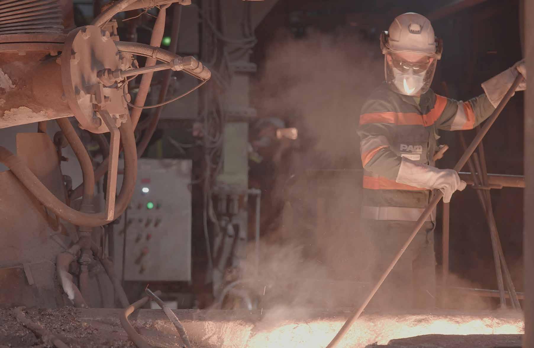
Cast iron solutions that contribute to the comfort, safety and durability of buildings

PAM Building - 1
SAFE AND SUSTAINABLE BY NATURE

PAM Building - 3 CONTENTS BUILDING SOLUTIONS & REFERENCES | 9 OUR SERVICES | 21 WHY USE CAST IRON? | 33 OUR SOLUTIONS | 65 PRODUCT CATALOG | 85 Wastewater | 86 Domestic use: PAM-GLOBAL® S − 86 Intensive use: PAM-GLOBAL® Plus & SMU Zn − 108 Rainwater | 122 Gravity system: Residential Type R − 122 Siphonic system: EPAMS® − 126 Infrastructure | 128 Itinero® − 128 Couplings, collars & connectors | 132 Supporting & fixing systems | 140 Accessories | 144 DESIGN & INSTALLATION | 147 GENERAL TERMS & CONDITIONS OF SALE | 191
PAM BUILDING, COMMITTED TO SUSTAINABILITY AND PRODUCT EXCELLENCE
For 150 years, we have been designing, manufacturing and supplying high-quality drainage systems for residential and commercial buildings and engineering structures.
We work exclusively with cast iron, a noble and durable material, of which we are a specialist and leader.
> As a leading manufacturer, we claim excellence in our processes, products and services.
> As a responsible manufacturer, we are at the forefront of sustainable performance to ensure we make the world a better home.
> As an innovative manufacturer, we put all our creative audacity into developing new, more specific and more efficient technologies, to deliver better products for your future needs.
PAM Building, a company built on the strength of its people, established in 3 major countries: France, England and Germany, and servicing the world
Over 360 employees
Sales in more than 50 countries
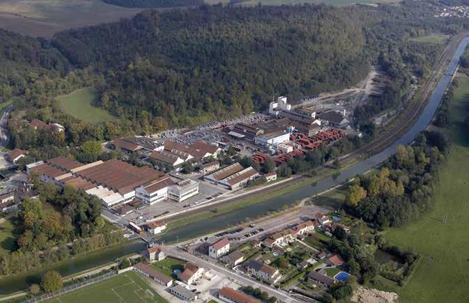
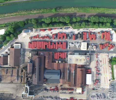
2 manufacturing sites for our products: Bayard sur Marne in France Telford in England
1st business in the cast iron industry to have published a third-party validated Environmental Product Declaration (EPD)

+38 : our indicator « Employee Net Promoter » that reflects the number of staff willing to become Ambassadors of the company (on a scale of -100 to +100)
35% female managers
1/3
internships and workstudy contracts converted to full employment contracts
As a member of the Saint-Gobain Group, a 350-year old world leader in providing innovative and sustainable construction products
168,000 employees and over 100 nationalities represented
10,000 production sites worldwide
An industrial presence in 75 countries
4 - PAM Building 01
CAST IRON, A MATERIAL WITH AWESOME CARACTERISTICS
FIRE SAFETY
ACOUSTICS
DURABILITY
CHEMICAL RESISTANCE
PRODUCTS THAT ADAPT TO THE CONSTRUCTION CHALLENGES OF TODAY AND TOMORROW
SOLUTION PRE-ASSEMBLY
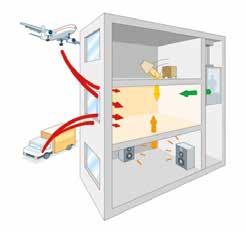
ELIXAIR® Earth-to-air heat exchanger
OUR MANAGEMENT SYSTEM FOR QUALITY, ENERGY AND ENVIRONMENT CONTRIBUTES TO THE CONTINUOUS IMPROVEMENT OF OUR ACTIVITY
9001 14001 50001
For PAM Building, being committed to sustainable development actions by ensuring its plants’ full compliance with current regulations is just the start.
Plants in the metallurgical industry call for greater vigilance and strict compliance with instructions, as the risks of serious accidents are particularly high.
The comprehensive approach adopted led us to obtain the ISO 9001, ISO 14001 and 50001 certifications for our plants and also recently BES 6001 for Telford site.

PAM Building - 5
SAFE AND SUSTAINABLE BY NATURE

COMMITTED TO REDUCING OUR IMPACT ON THE ENVIRONMENT
Our 2025 objectives vs 2010
Our commitment to reduce C02 emissions by 2030:
- 80% vs 2017
-40% CO2 (SCOPE 1 & 2)

-84% NON-RECOVERED WASTE

-97% DISCHARGED WATER

COMMITTED TO THE SAFETY AND DURABILITY OF BUILDINGS


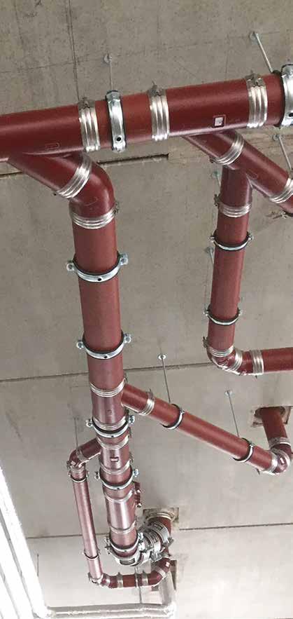
Our cast iron solutions and systems help ensure the comfort, safety and durability of the most demanding residential and commercial buildings.
Their exceptional characteristics allow them to contribute to HQE, BREEAM, LEED and other international environmental certifications...


> High-rise buildings

> Hotels
> O ces
> Hospitals and Health Centers
> Cultural buildings
> Structures dedicated to leisure

> Railway stations and airports


6 - PAM Building 01
OUR STRENGTH IS IN OUR PEOPLE
Our corporate culture attracts and develops the talents of the people in our teams over time.
We forge the technical competence that pushes us to the forefront of everything we do.


PAM Building believes in youth and proves it by integrating young graduates, its practice of apprenticeship and development.

Our commercial approach transforms us into providers of technical solutions to exceed our customers’ expectations.
Our team provides excellent service and technical support during the design, implementation of a project.
Our project managers ensure daily follow-up in the field to guarantee the best possible conditions for implementation.

OUR PRODUCTS, PEOPLE, TEAMS ARE HERE TO HELP YOU MAKE THE WORLD A BETTER HOME.


PAM Building - 7

BUILDING SOLUTIONS & REFERENCES
HOTELS HIGH-RISE BUILDINGS HEALTHCARE FACILITIES CULTURAL & LEISURE FACILITIES AIRPORTS INFRASTRUCTURES 10 13 14 17 18 19
HOTELS
Hotels are very special buildings since for a short time they act as a second home for the people staying in them. Customers therefore expect hotels to be restful and relaxing places. The higher the hotel is rated the higher the specifiers’ requirements for safety and comfort.

Wastewater and rainwater drainage systems are needed to maintain a peaceful and safe environment, requiring strong and durable materials, with minimal maintenance. Safe, totally watertight and silent in operation, the PAM cast iron drainage solution is the top choice for wastewater drainage systems in hotels.
Combining top-quality products and unrivaled longevity, the PAM cast iron drainage systems help maintain the sustainable and comfortable environment your building projects require.
CHEMICAL RESISTANCE
ACOUSTICS
FIRE SAFETY
DURABILITY
10 - PAM Building 01
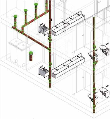
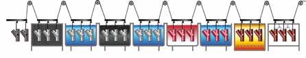
PAM Building - 11 01 6 5 3 4 1 2 Application areas FIT S Range RECOMMENDED Plus Range 1 Sanitary blocks (grey and black water) 2 Rainwater stacks 3 Car parks 4 Laundry, bleachery (chemicals + hot temp) 5 Restaurant kitchens (grease + hot temp) 6 Swimming pools (aggressive environment) S Range BUILDING SOLUTIONS & REFERENCES
HOTELS
WORLDWIDE REFERENCES
Rixos Tersane Hotel - Istanbul - Turkey
Premier Palace Hotel - Kyiv - Ukraine

City Of Dreams Mediterranean - Limassol – Cyprus
Sofitel Thalassa Hotel - Staoueli - Algeria
St Regis Hotel - Kula Belgrade - Serbia
Royal Mansour - Casablanca - Morocco
Jabal Omar Development Company, Phase 4 - Makkah - KSA

One & Only Aesthesis Resort - Glyfada, Athens - Greece
Ayia Napa Marina Villas - Ayia Napa Marina - Cyprus
Radisson Hotel - Bursa - Turkey
Sofitel Singapore City Center - Singapore - Singapore
Shangri-La Island Hotel - Honk Kong- China
Rixos Tersane Hotel - Istanbul - Turkey I S range

Premier Palace Hotel - Kyiv - Ukraine I S range
City Of Dreams Mediterranean - Limassol - Cyprus I S range
12 - PAM Building 01
1 2 3 1 2 3
HIGH-RISE BUILDINGS
WORLDWIDE REFERENCES
Capital Towers - Moscow - Russia
Lake View Residences - Tirana - Albania
Ziraat Bank Financial Center - Istanbul - Turkey

BADR Bank Headquarters - Algiers - Algeria
F Tower – Abidjan - Cote d’Ivoire

CFC Tower - Casablanca - Morocco
Trilliant - Tashkent – Uzbekistan
Central Bank of Azerbaijan - Baku - Azerbaijan
Kula Belgrade - Belgrade - Serbia
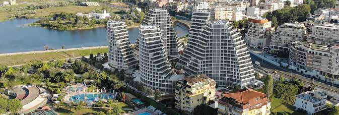
Downtown One - Tirana - Albania
Vodno Telecommunication Tower - Skopje - North Macedonia
Seef Lusail Residential Development Plots D3&D4 - Lusail - Qatar
PAM Building - 13 01
Tour Attijari Wafabank - Casablanca - Maroc
1 2 3
1 2 3 BUILDING SOLUTIONS & REFERENCES
Tour Attijari Wafabank - Casablanca - Maroc I S range - EPAMS® Capital Towers - Moscow- Russia I S range Lake View Residences - Tirana - Albania I S range
HEALTHCARE FACILITIES
Healthcare facilities have specific requirements that must be considered when designing wastewater drainage. Wastewater drainage systems in these buildings will face demanding operating conditions due to the types of e uents they carry, high operating temperatures and intensive use. In buildings dedicated to providing people with care, the pipe systems must meet more stringent requirements to maintain a safe and comfortable environment. To minimize the risk of ward closures or any disruption to medical care, the pipe system selected should require limited repair and maintenance.
CHEMICAL RESISTANCE FIRE SAFETY
E uents drained in healthcare facilities can be aggressive (especially from laboratories, etc.) and/or reach high temperatures (kitchens, laundry, etc.).


These characteristics must be addressed to protect the durability of the wastewater systems and avoid premature and costly repairs, liable to disrupt continuity of service.
The pipework is the building’s arteries, passing through structures - walls and slabsdesigned to contain fire.
In case of fire, the main risk for wastewater pipe systems, in addition to early collapse, is that they could fuel and potentially spread the fire.
Since a fire in healthcare buildings can have even more harmful e ects, careful selection of the pipe material is key to protecting both people and property.
ACOUSTICS
In healthcare facilities more than anywhere else, noise is an unacceptable nuisance, disturbing the patients’ rest and the staff’s attention. Among the noises emitted within buildings, some stem from equipment including pipework flow noises and airborne or structure-borne noise.
14 - PAM Building 01
SPECIAL TESTS CARRIED OUT ON PLUS INNER LININGS
The pipe sample (upper) and fitting sample (lower) were immersed for 30 days in di erent solutions widely used in hospitals in Europe for di erent purposes. The concentration and temperature were those recommended by the manufacturer. These severe tests aim to simulate accelerated ageing.
No damage was observed after the tests either on the PLUS pipe or the PLUS fitting samples.
PAM Building - 15 01
USE Operating temperature pH Hand soap 40°C 7.88 High-level disinfectant 40°C 5.45 High-level disinfectant 40°C 5.81 Detergent 50°C 9.37 Pre-disinfectant for medical and surgical instruments 30°C 7.3 Pre-disinfectant for medical and surgical instruments 20°C 6.9 Disinfectant for medical and surgical instruments 20°C 4.71 Disinfectant for medical and surgical instruments 55°C 11.8 Rinsing product and lubricant 55°C 6.37 Disinfectant and descaler for hemodialysis 20°C 3.92 Descaler for dishwasher 65°C 1.25 Cleaning product with biological action 60°C 7.52 S Range RECOMMENDATIONS S Range Plus Range Sterilisation, hemodialysis, OR Laboratories Departments dealing with aggressive fluids and/or high tempertures Wards, o ces, treatment rooms Laundry, bleachery Kitchens Car parks Grey wastewater, black water Aggressive and/or high-temperature fluids Rainwater Crawl spaces Grey wastewater, black water Aggressive and/or high-temperature fluids Rainwater Heliport
RANGES BUILDING SOLUTIONS & REFERENCES
> APPLICABLE
HEALTHCARE FACILITIES
WORLDWIDE REFERENCES
Acıbadem Hospital Atasehir - Istanbul - Turkey
Onassis Cardiac Surgery Center - Athens - Greece

CHU - Agadir - Morocco
Sidra Hospital - Doha - Qatar
Military Hospital - Tamanrasset – Algeria
Grange University Hospital - Wales - UK

CHU ABYME - Guadelouppe - France
Princesse Grace Hospital - Monaco
Bozüyük State Hospital - Bilecik - Turkey
Clínica Universitaria de Navarra - Madrid - Spain
Children’s Hospital - Helsinki - Finland
CHU Tangier - Tangier - Morocco
Acıbadem Hospital Atasehir - Istanbul - Turkey I S range
Onassis Cardiac Surgery Center - Athens - Greece I S & Plus ranges
CHU - Agadir - Morocco I S & Plus ranges

16 - PAM Building 01
1 2 3 1 2 3
CULTURAL & LEISURE FACILITIES
WORLDWIDE REFERENCES
Santiago Bernabéu Stadium - Madrid - Spain


The Pyramid of Tirana - Tirana - Albania
New Atatürk Cultural Center - Istanbul - Turkey
Istanbul Museum of Modern Arts - Istanbul - Turkey

Berraki Stadium - Algier - Algeria
Arribat Mall Center - Rabat - Morocco
Grand Theatre Rabat - Rabat - Morocco
Kai Tak Sports Park - Honk Kong - China
Shaw Auditorium - Hong-Kong - China
11 Skies Commercial Complex - Honk Kong - China
UAE Pavillion EXPO 2020 - Dubai - UAE
Munch Museum - Oslo - Norway
Oasis Mall - Doha - Qatar
Santiago
The
PAM Building - 17 01
Athens Music Hall - Athens - Greece
1 3 2
Athens Music Hall - Athens - Greece I S range
Bernabéu Stadium - Madrid - Spain I S range
1 2 3 BUILDING SOLUTIONS & REFERENCES
Pyramid of Tirana - Tirana - Albania I S range
AIRPORTS
WORLDWIDE REFERENCES
Çukurova Airport - Mersin - Turkey
Domodedovo Airport - Moscow - Russia
Geneva Airport - Geneva - Switzerland
Hong Kong Airport Terminal 2 Extension - China
Muscat International Airport - MC 5 - Muscat - Oman
Athens Airport Extension - Athens - Greece
International Airport Terminal 3 - Frankfurt - Germany
Changi Airport Terminal 4 - Singapore - Singapore
Ahmad Yani Airport New Terminal - SemarangIndonesia

Ahmed Ben Bellah International Airport - Oran - Algeria
Manchester Airport Terminal 2 - Manchester - UK
Çukurova Airport - Mersin - Turkey I S range
Domodedovo Airport - Moscow - Russia I S range

Geneva Airport - Geneva - Switzerland I S range - EPAMS®

18 - PAM Building 01
1 2 3
1 2 3
INFRASTRUCTURES
WORLDWIDE REFERENCES
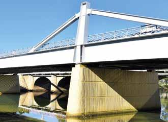
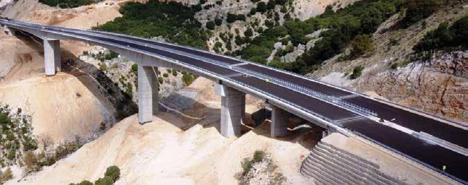
Dumbea Bridge - Noumea - New Caledonia
Central Greece Motorway E65 Bridges - Greece
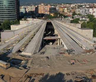
TGV Train Station - Kenitra - Morocco

Athens Metro - Athens - Greece
Gayrettepe - Istanbul Airport Metro - Istanbul - Turkey
Eurasia Tunnel - Istanbul - Turkey
Cross Yarra Rail Tunnel - Melbourne - Australia
Mont Blanc Tunnel - Haute-Savoie – France
Tournon Viaduct - Savoie - France
Kula Vodno - Skopje - North Macedonia
Doha Metro - Doha - Qatar
Step Project - Abu Dhabi - UAE
PAM Building - 19 01
1 2 3
Dumbea Bridge - Noumea - New Caledonia I Itinero®
Central Greece Motorway E65 Bridges - Greece I S range
1 2 3 BUILDING SOLUTIONS & REFERENCES
TGV Train Station - Kenitra - Morocco I S range - EPAMS®

TECHNICAL SUPPORT BIM SERVICES CUSTOMER SERVICES DIGITAL 22 26 28 30
02 OUR SERVICES
TECHNICAL SUPPORT
DESIGN STUDIES
To help our customers define the most optimised network for EPAMS®, ITINERO® or ELIXAIR® systems, our technical support team designs solutions and provides drawings and bills of quantities.
EPAMS®
You have a project to discharge rainwater on a flat roof and you want to quickly define the details and costs of the EPAMS installation (see also p.178).
Send us:
• Your drawings in DWG format (roof, levels, section views, etc.)
• The general rainfall intensity of your country (in mm/hr or l/s.m)
You will receive a response within 2 days concerning the feasibility and an initial design study*.
*Full studies are conditional upon the final order of the materials.
ITINERO®
For our new dedicated range of bridges and tunnels (see p.76), we can support you with the system’s complete design.
Send us:
• The drawing of the bridge
• The drainage location (outlet and collector) in DWG format
We will provide you with:
• A design recommendation
• The discharge system’s set-up
• A bill of quantities
22 - PAM Building 02
ELIXAIR®
With global warming and the growing importance of energy e ciency, our earth-to-air heat exchanger ELIXAIR® system (see p.78) is becoming increasingly specified.
If you are asked to quote ELIXAIR®, send us your project and we will be able to help you with the supply of:
• Your earth-to-air heat exchanger
• The bill of quantities
• The heat energy saved in winter
• The cooling energy saved in summer
ESTIMATE YOUR PROJECT
You have some doubts before finalising your quotation. PAM Building has set up a service for you.
Send us the drawing of the discharge system’s location with details of the pipe diameters in the following formats: DWG (preferred), RVT or PDF.

Based on general plumbing rules, we will provide you with the general bill of quantities including:
• The numbers of the parts
• The references to order
PAM Building - 23
02 OUR SERVICES
02
TECHNICAL SUPPORT
TECHNICAL EXPERTISE & INSTALLATION RECOMMENDATIONS

Our service portfolio is fully aligned with the new expectations of MEP consultants and contractors working on safe, comfortable and durable building projects.
In addition to our recommendations in this catalog, if you have any questions, you can ask our experts on the following topics:
• Acoustics (p.44)
• Fire protection (p.40)
• Technical and functional advice (see “Design & Recommendations” section)
• Environmental building certifications (p.63)
JOB SITE DIAGNOSIS
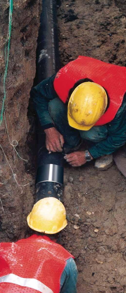
Drainage pipe systems are often considered utilitarian. As non-visible arteries, they are often poorly maintained and neglected in renovation planning, yet they can ruin the lives of the buildings’ occupants by causing major damage.
PAM Building therefore o ers a diagnostic service. The company has decades of experience which has resulted in:

• Creation of a database of the disruption and failures experienced on pipework systems
• Many requests for expertise because cast iron used to be the market’s technical reference
We can either perform the diagnostic ourselves (chargeable service) or train your teams to perform it, to avoid part renovation which brings further disruptions.
To help us provide professional services, we are equipped with:
• Hygrometer
• Temperature sensor
• Toximeter (measurement of hydrogen sulfide)
• Inclinometer
• Fluorescein
• Ultrasonic sensor
• Feedback
BESPOKE DEVELOPMENT
Upon request, PAM Building can provide special designs of fittings outside the ranges o ered in our catalog*. Send us your details and we will provide a response concerning the feasibility within two days.
The latest example is the 125 x 100 x 100 mm Double Branch, which is now available in our product range.
How does it benefi t the owner or maintenance team?
• Get a global picture of the wastewater and rainwater pipe systems
• Perform an audit of pipe discharge drainage
• Map and date the pipework, analyze the interactions and assess the condition
After diagnosis you will have a list of recommendations, with a view to guiding professional interventions, carried out in compliance with regulations and best practice.
For more information, contact us: tcbatiment.sgpam@saint-gobain.com Tel: +33 (0)3 66 74 00 89
PAM Building - 25
02 OUR SERVICES
*Sales to order only
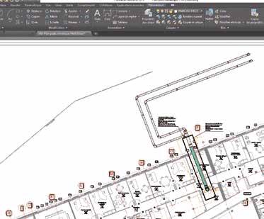
PAM Building aims to ease the burden on developers, specifiers and contractors in the early stages of construction by providing two levels of BIM library and supporting information.
The new releases include a full-data objects library, a platform that provides supporting information and free individual BIM files for all products and systems.
These include an EN 877 “Generic Cast Iron” content package for use in the early design stages, with parametric model fittings, and standard geometric settings. The files contain only the most vital information, reducing the time and e ort required to create early stage plans. These “data-light” designs

can also be overwritten with the full data specification libraries without issue, speeding up later stages of development that require more detailed plans, streamlining the transition from design to as-built work flow.
PAM Building Libraries are designed to aid data transmission between the consultants and the Main Contract MEP design engineers, creating a leaner process that reduces design time.
By providing small file sizes for the generic content, it will facilitate early stage specification in BIM and speed up the whole planning process; this in turn will create measurable cost and time savings for our customers.
PAM Building has been developing BIM Level 2 libraries in Revit for its domestic use (S), siphonic rainwater (EPAMS®) and intensive use (Plus) ranges.


02
EN
IRON
BIM
S RANGE BIM LIBRARY EN877 PLUS RANGE BIM LIBRARY EN877 Available content on bimlibrary.saint-gobain.com
877 CAST
GENERIC
LIBRARY
BIM
Contact our technical support team: tcbatiment.sgpam@saint-gobain.com Tel: +33 (0)3 66 74 00 89
NEW REGISTRATION REQUIRED TO KEEP UP TO DATE WITH NEW/ REVISED CONTENT

FULL PARAMETRIC PIPE SYSTEMS GENERIC AND FULL DATA
ACCESS TO GUIDANCE VIDEOS AND ‘HOW TO?’ FAQS

EN 877 CAST IRON GENERIC LIBRARY
• Generic cast iron content
» Full range of cast iron fittings
» All families have ‘real geometry’
» Generic coupling with ‘fixing zone’ visibility
» All fittings have constrained couplings which can be turned on/o

» No ‘manufacturer’ data
» All files are light at 500 KB max
PAM CAST IRON LIBRARY
• Full data content
» Minor modifications to project design stages
» Time saving design for main contract BIM Engineers

PAM Building - 27
02 OUR SERVICES
CUSTOMER SERVICES
WE SELL PRODUCTS ALL OVER THE WORLD
With 150 years of experience in worldwide export sales, our international organization obtains all our customers’ feedback which we need to help us constantly improve our products and services. OUR CUSTOMER SERVICE TEAMS WILL BE HAPPY TO HELP!

To optimize its customer service, PAM Building has an integrated network of subsidiaries, agents and distributors which can rely on dynamic and experienced technical sales teams to provide excellent customer support.

For enquiries, our customer service is available from Monday to Friday from 8:30 am to 5:30 pm (French time): Phone : +33 3 83 80 76 50 / 53 / 54 Fax : +33 3 83 80 76 57
You can also find the contact details of our sales area manager on our website.
28 - PAM Building 02
WE PROVIDE LOGISTICS SERVICES
Every day, PAM Building ships a wide range of products to provide its customers with complete, operational solutions wherever they are. Depending on your needs and practices, you can either manage the transport yourself or we can quote you in accordance with the Incoterms you wish to contract with us. To speed up the process, we have signed an agreement with French Customs.
PAM Building - 29
EXW Ex-Works RULES FOR ANY MODE OF TRANSPORT RULES FOR SEA AND INLAND WATERWAY FCA Free Carrier CPT Carriage Paid To CIP Carriage and Insurance Paid To DAP Delivered at Place DPU Delivered at Place Unloaded DDP Delivered Duty Paid FAS Free Alongside Ship FOB Free On Board CFR Cost and Freight CIF Cost Insurance and Freight SELLERS COSTS BUYER’S COSTS TRANSFER OF RISK INSURANCE 02 OUR SERVICES

30 - PAM Building 02 Visit our website ! www.pambuilding.com DIGITAL
Follow the latest news from PAM BUILDING on Linkedin


Discover our YouTube Channel !


In our YouTube channel, you find installation tutorials of cast iron pipes, fittings and couplings, as well as informations about products, BIM service, production facilities, news and commitments.


PAM Building - 31
Follow us on Follow us on 02 OUR SERVICES
01
WHY USE CAST IRON?
STANDARDS & CERTIFICATIONS FIRE SAFETY ACOUSTIC COMFORT DURABILITY CHEMICAL & CORROSION RESISTANCE ENVIRONMENT 36 40 44 48 54 60
WHY
USE
CAST IRON?
CAST IRON SYSTEMS, AN OBVIOUS CHOICE
As a leading manufacturer and the world’s top-ranking exporter of cast iron pipe systems for building drainage applications, PAM Building is an essential partner for wastewater and rainwater drainage system designers. PAM Building cast iron products are safe, easy to install and e ectively meet project managers’ requirements. We provide di erent ranges to suit all building types and specifications.
CAST IRON PIPES GIVE OUR WASTE A SECOND LIFE
Cast iron products for building drainage systems are made of an alloy : iron, carbon and silicon. Cast iron is manufactured entirely from recycled raw materials: scrap iron and cast iron which are enhanced by a second melting process.
PAM Building cast iron combines the traditional longevity of iron with outstanding technical and mechanical properties which remain stable over time in all climates. Its robustness limits breakages and damaged supplies, and its nature and density confer thermal and acoustic properties guaranteeing safety and comfort in use.
MAIN CHARACTERISTICS OF CAST IRON
• Quick standard installation with mechanical couplings assembled with simple tools, without gluing or welding, which can save time and labor costs.

• No expansion joints which facilitates the design and saves on expensive thermal limiters.

• No systematic fire protection or fire collars due to its fire behavior.
• Less protection for acoustic insulation due to its acoustic properties, resulting in plasterboard savings while achieving the same performance.
• Less embedment than other materials in buried applications where ground disturbance or extra loading is likely.
34 - PAM Building 03
DURABILITY AND LESS MAINTENANCE
Cast iron has a proven 70-year lifespan due to its outstanding mechanical properties and safety margin in operation.
• Cast iron systems withstand cleaning operations, even at high pressure. They also withstand traditional unblocking chemicals and enzymes without damage: PAM Building is continuously carrying out research on its coatings to maintain such qualities.
• Cast iron in exposed sections of the drainage system, i.e. basement car parks, is more resistant to damage than other drainage materials. It is also less sensitive to cracks and breakage prior to installation.
• Cast iron below ground o ers greater resistance to ground movement, and is less likely to fail in unfavorable conditions.
With our networks, maintenance operations are limited.
• Cast iron drainage requires minimal maintenance during the lifetime of the building under normal conditions, making it the first choice for concealed, built-in or otherwise inaccessible systems, where repair or maintenance would cause major inconvenience to the occupants.
• Where necessary, removable mechanical couplings make repairs easier and cheaper without cutting into the stack. An extensive range of access parts provides ease of maintenance at vital points in the stack to relieve any blockages which may occur.
• In the event of destination changes in the premises or the addition of devices, the PAM systems, whose junctions are not glued or welded, can be modified without having to break or cut them, by simply removing the joints.
PAM Building - 35 03 WHY USE CAST IRON?
STANDARDS & CERTIFICATIONS
PRODUCT PERFORMANCES
PAM Building pipe systems comply with European standard EN 877, applicable to a system (cast iron pipes and fittings, couplings and accessories for building drainage). This standard, specifying the technical requirements for cast iron products, is the most stringent in the market.
In particular, it specifies requirements regarding:
• Reaction to fire (product range)
• Resistance to internal pressure
• Dimensional tolerances
• Tensile strength, crushing strength
• Joints and their leak tightness
• Inner lining and external coatings and their suitability
It also defines test methods and the quality management system. Except for reaction to fire properties, EN 877 is a self-declared standard; the manufacturer is allowed to self-declare that their product complies with this standard.
Only compliance with EN 877, which is validated by a third party for all criteria and periodically tested, can guarantee the performance of the systems you specify.
The quality of product ranges is guaranteed by quality marks: Marque NF, RAL-GEG, Kitemark, BBA, Sintef, Gost, Q+.


Cast iron pipes and fittings, their joints and accessories for the evacuation of water from buildings - (Requirements, test methods and quality assurance)
Elastomer seals - Material requirements
Requirements for a quality management system design, product development, production, installation and after-sales support

Environmental management system - (Requirements with guidance for use)
Energy management system
Testing standards
Fire tests
Fire classification of construction products and building elements.
Classification using data from reaction and resistance to fire tests
Reaction to fire tests for building products - Part 1 Building products excluding floorings exposed to thermal attack by a single burning item
Measurement of noise
Laboratory measurement of noise from wastewater installations
European standards International standards
EN 877
EN 681-1
ISO 4633
ISO 9001
ISO 14001
ISO 50001
EN 13501-1
EN 13501-2
EN 13823
EN 14366
36 - PAM Building 03
CE MARKING: WHY IS IT REQUIRED?
The European Construction Products Regulation made CE marking mandatory on products for which the manufacturer has drawn up a declaration of performance.
The CE marking indicates that manufacturers take responsibility for the construction product’s conformity with the declared performance as well as compliance with all applicable requirements laid down in the European Construction Products Regulation.
• To allow for free circulation of industrial products within the European Union and the European Economic Area
• To guarantee that these products are not dangerous to European consumers and users
• To have the same safety criteria shared throughout Europe
Fire safety was selected as the only essential requirement for the CE marking on wastewater products, which must be supported by laboratory tests conducted at recognized independent facilities. This led to a “Reaction to fire” classification in the Euroclass system.
Our cast iron drainage systems are manufactured to harmonised European standard EN 877 and have therefore required CE marking by law since July 2013. Although it is not a quality standard, the CE mark is a self-declaration of product performance with the exception of reaction to fire, which requires mandatory certification by independent tests at a recognised fire testing center.
CE marking is not a quality mark or label It is something very di erent
The CE mark is NOT a quality mark but a self-declaration of product performance (DoP) in reference to its product standard (with the exception of reaction to fire which requires independent testing at a recognised fire testing center).
The CE marking on a product certifies that it complies with the harmonised part of the reference standards and is a minimum prerequisite for placing the product on the market.
Except for the reaction to fire class, the third-party certification of the performances is not guaranteed by EN 877, but by one of the following marks: Marque NF, RAL-GEG, Kitemark, BBA, Sintef, Gost, Q+.
Third-party certification not made compulsory by EN 877 Third-party certified
PAM Building - 37 03 WHY USE CAST IRON?
SCOPE
TEST CE MARKING THIRD PARTY CERTIFIED Reaction to fire Internal pressure strength Dimension tolerance Mechanical resistance Tightness Durability (internal coating) Durability (external coating)
Performance (DoP)
our
our
HARMONIZED EN 877
A summary of the Declaration of
for all
ranges is available on
website: www.pambuilding.com
STANDARDS & CERTIFICATIONS
To comply with the CE mark, PAM Building cast iron drainage systems bear a quality mark to demonstrate the product’s standard:
• Our system complies with all of the standard’s clauses.
• We are periodically audited by a third party.
• This gives you the ultimate quality guarantee.
Choosing a complete and consistent range of cast iron products, whose assembly has been performance tested against regulatory requirements, provides you with peace of mind that few other materials can guarantee.
PRODUCT MARKINGS
Pipes
Fittings
The identification marking for PAM Building fittings is a label. Marking also identifi es the manufacturing site.

38 - PAM Building 03
Compliance with the RAL-GEG mark Compliance with the DIN EN standard Product name CE marking / Reaction to fire classification Standard conformity Pipe size
QUALITY MANAGEMENT SYSTEM


The plants which manufacture our products are certified for their compliance with the ISO 9001 standard which specifies requirements for a quality management system. The scope of this standard covers product design and development and the quality control of procurement, training, and administrative follow-up.
MADE IN
PAM Building - 39 03 WHY USE CAST IRON?
Bayard plant (Haute-Marne): ISO 9001 and ISO 14001 certified by Bureau Veritas.
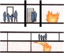
FIRE SAFETY
Drainage systems are the arteries of a building. In case of fire, there is a risk that pipes will maintain and spread the fire in the building. Pipe penetrations through a separating element like a wall or a slab are always a source of risk for the spread of fire to the adjacent room, the floor below or the floor above. As regards a building’s fire safety, the major responsibility rests with the project manager who must comply with local regulations. Accordingly, and particularly in high-risk buildings like high-rise
REACTION TO FIRE
This is the instant behavior when a fire breaks out, its propensity to ignite or fuel a fire. This behavior is assessed on the basis of standardised tests and described in a Euroclass classification.
The Euroclasses are based on test methods and establish reaction to fire classifications that are harmonised throughout Europe. This means they can be used to compare materials and product performances.
buildings, materials with reduced flammability should be selected as a precautionary measure.
PAM Building is committed to the development of high-quality and high-safety products. Fire safety is one of the main technical performances of our products. In choosing PAM Building cast iron systems, you are guaranteeing the safety of both people and property.
There are two concepts applied to fire safety: reaction to fire and fire resistance.
EUROCLASSES
Classes
s1: Low smoke production
s2: Medium smoke production
s3: High smoke production
FLAMING
DROPLETS
d0: No flaming droplets
d1: Flaming droplets that persist for less than 10 s
d2: Flaming droplets
40 - PAM Building 03
SMOKE production sub-classification
sub-classification
A1 -A2 s1 d0 A2 s1 d1 A2 s2 s3 B s1 d0 s2 d1 s3 C s1 d0 s2 d1 s3 D s1 d0 s2 d1 s3
The Euroclass classification ranges from A1 to F, with A1 and A2 being reserved for products that are not, or are only slightly, combustible. The indices s and d respectively refer to smoke emission and the production of flaming droplets. other than E-d2 and F
PAM Building cast iron systems are among the safest materials on the market in terms of reaction to fire, and all its drainage systems have been tested independently to the stipulated test criteria.
In tests carried out by the CSTB accredited laboratory, the PAM Building cast iron ranges (pipes, fittings and accessories, including elastomer gaskets and coatings) received the following excellent Euroclass ranking: A1 for our standard “S” range and A2-s1, d0 for the “Plus” range.
Scope
The CE marking for cast iron wastewater systems is based on the harmonised standard EN 877, which applies to a system including pipes, fittings, couplings and accessories, and is used to test all of the ranges’ components.
The classification obtained by PAM Building covers complete ranges: pipes, fittings, couplings and accessories that are components of a wastewater pipe system.
Check the reaction to fire classification of the products you specify, and ensure the tests were carried out by an accredited testing centre. This compliance is validated by complete quality marks, is periodically tested by accredited third-party laboratories and provides you with a performance guarantee for the systems you specify.
ADVANTAGES OF OUR SOLUTIONS
→ A1 Euroclass Rating for the S Range –it is completely non-combustible!
→ No smoke and no flaming droplets in the event of a fire.
PAM Building - 41 03 WHY USE CAST IRON?
A1
A2 - s1, d0
Cast iron remains one of the best materials when it comes to fire safety.
FIRE SAFETY
FIRE RESISTANCE
This is a construction component’s ability to withstand fire for a given period of time and to retain its serviceability in the event of fire, avoiding the spread of fire. If a fire breaks out, it is essential to prevent any early collapse of the structure, and then limit the extent of the damage to ensure that occupants can be evacuated and/or belongings will be protected. Many buildings are not su ciently protected against fire hazards. This means that fire can spread quickly, destroy the building in a short time and, more importantly, endanger the lives of the occupants. When a fire breaks out, the first objective is to slow down its spread both horizontally and vertically.
The main causes of fire are:
• Faults in electrical systems
• Human error
• Overheating
• Arson
Lightning strikes or explosions play a minor role in the statistics here, but can lead to a chain reaction of fires if they do occur (Source: www.ifs-ev.org).
The fire resistance performance level will be influenced by a number of factors: the pipe diameter, the thickness of the floor or wall, the size of the penetration void, the material used to seal the void and even the stack configuration through the penetration.
Compartmental principle
When they exist, fire safety regulations for buildings are based on a compartmental principle. Within a building, a compartment is a fire rated space designed to stop the fire for a given period of time. The fire stopping requirement for walls (shells and slabs) is generally 2 hours or less - and exceptionally 4 hours.
The requirement depends on the type of building and its level of occupancy, and can be very different from one country to the next.
42 - PAM Building 03
Wastewater drainage systems and fire stopping requirements
Drainage systems passing through structures designed to withstand fire should not provide open breaches. For a given time, specified in the applicable regulations, they should not allow the passage of fire, smoke, heat or combustion products from one compartment another.
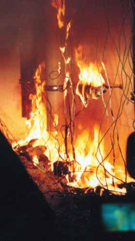
Cast iron, a non-combustible material, has a melting point of over 1000°C. In most cases it requires no additional fire protection.
PAM Building has and will continue to periodically test its cast iron drainage systems with standard mortar penetrations and other solutions in order to understand the potential e ects of fire on its integrity, resistance and overall performance. We carried out a non-exhaustive series of tests to o er precise guidance for fire resistance.
Our systems proved to meet integrity and insulation requirements up to 240 minutes (4 hours)*, and should therefore not collapse causing potential danger to evacuating people or firefighters.
We regularly perform new tests. Therefore, if you have any questions our technical team can provide guidance and help you select the right configuration for optimal performance and provide you with a comprehensive report. You can contact our technical support team on our website: www.pambuilding.com.
COMPARISON WITH OTHER MATERIALS
For plastics, the fi re stopping rule consists in “plugging the hole”. This function is achieved by using fire collars recommended by the manufacturers. Plastic materials, which are highly sensitive to heat, will not withstand fire, and will not remain in place, even in the case of a contained fire. As shown by laboratory tests in Germany, if the fire collars are not activated, particularly when installed under the fire compartment, they significantly increase the risk of the fire spreading downwards in a multi-storey building. When some types of plastic material (e.g. HDPE and Polypropylene) are exposed to fire they generate molten droplets, which could potentially spread a fire down through the building.
Exposed to fire, plastic material releases toxic fumes and gases, which beyond a certain amount may be fatal to the people inhaling them.
* Furnace tests carried out in 2017-2018 according to EN 1366-3 at the EFECTIS testing centre, the European leader in fire science, engineering, tests, inspection and certification.
Choosing PAM Building
cast iron drainage systems guarantees the safety of both people and property.
PAM Building - 43 03 WHY USE CAST IRON?
limit ed t emper atur e heat flames
flammables gas
ACOUSTIC COMFORT
Noise in buildings is considered to be detrimental to health and quality of life. Efforts have been made in the last 30 years to attenuate the sounds coming from the street, worsening the perception of sounds emitted within buildings. Heat insulation policies aimed at reducing energy consumption will also heighten these perceptions. Among the priority criteria in the comparative performances of drainage materials, acoustic performance is considered to be second only to fire safety: cast iron pipe systems have intrinsic acoustic properties. Owing to the development of equipment accessories, they offer outstanding performances.
WHAT IS NOISE? NOISE FROM PIPE SYSTEMS
Noise from wastewater pipe systems is classified in the regulation under “equipment noise”. Noise originating from pipe systems is due to the sound energy produced by water/ air turbulence, but mostly by the mechanical e ect of the water flow on the internal pipe walls. In such circumstances a pipe will radiate noise outward and transfer it to any lightweight ceilings, cupboards and similar areas wherever it makes contact.
Noise is an energy that a ects air pressure and is transmitted through vibration.
Sound is measured in decibels (dB) using a nonlinear scale. For equipment noise, the following categories are identified and measured:
Airborne noise:
Airborne noise vibrations that are propagated. In the case of wastewater pipe systems, this noise is mainly heard in the room where the pipe is located. When a material is dense and thick, the pipe walls prevent air-borne noise transmission, as is the case with cast iron which has intrinsic acoustic properties.
Structure-borne noise:
The vibration of a building’s structure. This noise will be noticed in rooms adjacent to the pipe. When the noise produced in a pipe is not transmitted by the air, the residual noise is transmitted by structural vibrations. Whilst the mass of the cast iron limits the vibratory level, the junctions and fixings to the building will propagate noise. Objective: dampen the vibrations at the connections to the solid structure.
Statutory requirements for “equipment noise” for structure-borne noise di erentiate between noisy rooms and quiet rooms with sound attenuation requirements. For noisy rooms, the noise level requirements are generally 35 dB or more. For quiet rooms, which are generally living rooms, resting rooms and work rooms, the noise level requirements are generally around 30 dB, in cases where noise regulations exist.
44 - PAM Building 03
COMPARATIVE LABORATORY TESTS
Acoustic comfort is a di erentiation criterion that indicates construction quality. The building project manager and specifier may define together specific requirements to improve the final construction.
In 2019, PAM Building commissioned a series of comparative tests on airborne and structure-borne noises in installation conditions described by standard EN 14366*, at the Fraunhofer Institute for Building Physics in Stuttgart.
The measurement results for the PAM Building cast iron pipes listed in the table were determined at the Fraunhofer Institute for Building Physics on an installation wall with a basis weight of 220 kg/m2
The prerequisite for this was that the building conditions in the real construction situation be comparable to or more favorable than the test bench of the Fraunhofer Institute for Building Physics in terms of sound technology.
When compared with the requirements, pay attention to the simultaneous operation of plumbing installations and possible interactions among the plumbing components which may produce di erent results. As a comparison value with the requirements, the measured value should be obtained at a flow rate of 2.0 l/s, because this corresponds to approximately one toilet flush. The sound measurements were taken both on the opposite side of the installation (in the picture on the right) and in the mounting room (on the left of the picture).
Details of the test configuration:
> Standard bracketing: 2 bracket collars per floor. Both mounted with a 1 Nm torque.
> Stack support: Stack supports are fixed to the wall/floor.
> PAM’Acoustic: 2 anti-vibration brackets per floor. Both mounted with a 1 Nm torque.
DG: Attic
EG: Ground floor In front
UG: Basement In front
The test results are on the next page
PAM Building - 45 03 WHY USE CAST IRON?
*As all wastewater pipe systems manufacturers apply the standard test protocol, it allows building project managers to compare their results.
ACOUSTIC COMFORT

Tests results for the installations, according to EN 14366
Complete reports are available on request. Sound levels below 10 dB(A) are not mentioned in the test report.
Structure borne noise & Pam’Acoustic
For the requirements of extreme acoustic comfort (luxury buildings, auditoriums...), Pam’Acoustic is an acoustic dampener, which, placed between the frame and the support collar of the cast iron pipe, makes it possible to achieve the exceptional structural noise level of < 10 dB (A), that is, almost silence.


46 - PAM Building 03
Pipe system Test report N° Installation acc. to EN 14366 Airborne noise (La,A) Structural noise (LSC,A) 2.0 (l/s) 4.0 (l/s) 2.0 (l/s) 4.0 (l/s) S range + classical bracketing with rubber and stack support in basement floor P-BA 223/2019 47 dB (A) 50 dB (A) 21 dB (A) 26 dB (A) S range + PAM’Acoustic without stack support in cellar P-BA 226/2019 47 dB (A) 50 dB (A) < 10 dB (A) < 10 dB (A) 21 < 10 7 128
NOISE IN REAL CONDITION OF USE
Usually pipe systems are installed in a technical shaft that contributes to reducing the noise emitted by the e uent flowing in a pipe. Nevertheless, the noise level of pipes installed behind a shaft may not be su cient to comply with the specifications of the owner or set by the national regulation.
In 2018, PAM Building initiated several noise measurement tests with an independent laboratory in real conditions, inspired by standard EN 14366, but using a real WC flush to assess the noise level of the combination of pipe material and shaft acoustic performance (∆Lan).
Below are some examples of measurements at a flow rate of 2 l/s with the S range fixed on a 15 cm thick supporting concrete wall:
SUMMARY OF OUR SOLUTIONS:
→ High basis weight
→ Low tendency to vibrate
→ Effective sound decoupling
→ High insulation value

→ Suitable for all pressures
→ Sewage installations
→ Precise installation instructions
→ Compliance with project specifications or regulations
Depending on your project specification or national regulation, PAM Building can help you validate your pipework’s compliance.
Please contact our technical support team on our website: www.pambuilding.com.
PAM Building - 47 03 WHY USE CAST IRON?
Technical Shaft S range with rubber lined steel brackets
∆ LanPerformance LA,S,max [50-5000 Hz] (dB) LA,S,max [50-5000 Hz] (dB) 19 ≤ ∆ Lan < 24 33 32 24 ≤ ∆ Lan < 29 30 25 29 ≤ ∆ Lan < 34 29 19
S range with steel brackets and acoustic dampener
Choosing our systems guarantees the best acoustic solution on the market.
DURABILITY
ROBUSTNESS AND MECHANICAL STRENGTH
Pipe system components must withstand hazards before they reach the job site such as accidental impact before and during installation, during storage, handling and transit. In service, outdoor exposed pipes may be damaged by accidental impacts or vandalism. To avoid breakages, which can be expensive, or minor stress cracks which can have serious consequences in operation, the choice of material should be carefully considered.
Impact strength and crush resistance
Compared with other materials, cast iron provides much better impact resistance and is highly recommended everywhere pipes may be exposed to mechanical shock (car parks, streets, etc.).
Cast iron is well known for its robustness. The quality of PAM Building products is ensured by careful control of both the metal composition and the manufacturing process.
The spinning of pipes in the De Lavaud process, followed by heat treatment, gives these products outstanding mechanical properties.
The advantages of the De Lavaud process: better mechanical characteristics, superior to the requirements of EN 877*
• Very good resistance to crushing.
• Increased impact resistance.
• The pipe is more resistant to mechanical stress such as bending and compression.
• For installers, installation is more comfortable and on-site handling is facilitated. Cutting pipes is easier, the slices are sharp. The set-up is therefore simpler and faster.
DE LAVAUD PROCESS
In this process, a constant flow of molten metal at a perfectly controlled temperature and composition is gradually put into a steel mould rotating at high speed. The mould external wall is cooled by circulating water and the evenly distributed molten metal cools on contact with the wall before extraction.
The process is characterized by quick cooling which gives a finer solidification matrix and thus a more homogeneous metallurgical structure.
The spun pipes are placed and rotated in a heat treatment furnace at 950°C and then gradually cooled again. This step is essential to the process as it transforms the cast iron’s metallurgical structure.
The reduction in iron carbides and the increase in ferrite content considerably improve the mechanical properties of cast iron and reduce its surface hardness. The graphite of the cast iron resulting from the PAM Building process forms clustered graphite, halfway between lamellar and ductile iron.
48 - PAM Building 03
These results indicate greater resistance to impacts and crushing, easier machining and cutting. This also means the products are easier to install on job sites.
*Key mechanical characteristics required by standard EN 877 are checked by three tests, carried out on pipes when coming out of the heat treatment furnace to assess tensile strength, ring crush resistance and hardness. In addition, operators have opted to perform a further test which provides a good indication of the heat treatment quality: impact test.
STABILITY TO THERMAL VARIATIONS
Most solids expand when heated and are liable to elongate under temperature increases. For pipe systems made of materials that are subjected to high levels of thermal expansion, precautions must be taken at the design stage.
Cast iron, which expands very little, does not require specific bracketing or expansion collars. It makes the specifiers’ design work easier and avoids extra costs at the installation stage.
Thermal expansion coe cient of cast iron and other materials
The thermal expansion coe cient for cast iron – 0.01 mm/m. °C – is very low and very similar to that of steel and concrete; the building and pipe systems will move and expand together.
For cast iron, the bracketing system is designed to only carry the weight of the pipe and its content, which makes the designers’ work easier. Plastic pipes, however, expand considerably with increasing temperature. Their bracketing system must be designed and adapted accordingly, as it can significantly a ect the pipework’s stability and performance over time.
Thermal expansion of plastics
To allow expansion without damaging the drainage network, plastic pipe systems require specific accessories –expansion collars or joints, brackets allowing axial movement, in general one of the two. If these precautions were not taken, expansion could be absorbed by the pipework and cause distortion.
Cast iron does not require these expensive accessories. It makes the design work easier and decreases the risk of mistakes at the installation stage.
These properties of cast iron pipe systems are also valuable for engineering structures such as bridges, where significant expansions have to be carefully addressed to secure the construction project.
PAM Building - 49 03 WHY USE CAST IRON?
The Pipes PAM Building process Others EN 877 requirements Tensile Strength on samples in MPa (average value) 300 270 200 minimum Ring Crush Strength in MPa (average value, DN 100 pipes) 450 360 350 minimum Brinnell Surface Hardness in HB degree (average value) 220 245 260 minimum Thermal expansion of cast iron and other materials for a temperature rise of 50°C and 10 m Thermal expansion cœ cient 0.0104 mm/m°C → 5.2 mm Cast iron 0.07 mm/m°C → 35 mm PVC 7 times more 0.150 mm/m°C → 75 mm PP 14 times more 0.17 mm/m°C → 100 mm HDPE 19 times more
WATERTIGHTNESS
Sanitary drainage systems, whether exposed or not, must remain watertight over time. Any defects can cause serious damage, leaks, dripping or slow permeation and generate costly repairs, and disruption. PAM Building cast iron mechanical assemblies are designed to easily achieve instant watertightness and are not dependent on process control (gluing or welding, etc.).
Watertightness of cast iron systems
Cast iron is a dense and non-porous material. Cast iron pipe systems are watertight and impervious.
Straight and rigid cast iron components are assembled using metal couplings fitted with elastomer gaskets which ensure the system is completely watertight.
Assemblies benefit from a conventional approach. Put together with only simple tools, they allow installation tolerance with no risk of leaks.
This ease of installation ensures the specified performance is always obtained, even in adverse conditions, unlike with plastics when either gluing or welding can be affected by installation hazards (ambient conditions such as temperature or damp), or when personnel with special skills are required.
Watertightness over time
Failure of watertightness can occur on drainage systems in operation due to breaks,
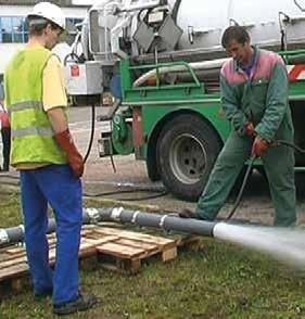
The S and Plus ranges, assembled and anchored, have successfully passed a high-pressure jetting test: cleaning pressure of 120 bar from the pump, which means 100 bar at the nozzle outlet, without leaks or misalignment.
misalignments, crushes or cracks. Long-lasting watertightness depends on two main factors:
• No deterioration of pipes: Cast iron is highly resistant to ovality. Their specified mechanical properties and stability enable cast iron systems to withstand operating stresses extremely well.
• No deterioration of assemblies: Elastomers are carefully selected for the long-term stability of their physico-chemical characteristics to ensure the lasting watertightness of the rubber gaskets.
50 - PAM Building 03
DURABILITY
SPECIFIC POINTS OF THE PIPEWORK: RESISTANCE TO END THRUST EFFORTS
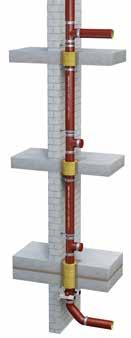
Some specific points on a pipe system may be subjected to thrust loads due to changes of direction and gradient, branches and plugs. To avoid any risk of disconnection or slippage of the pipe components, these loads must be addressed and the sections at risk must be anchored:
• A straight section of pipes may be held between two fixed points with ductile iron brackets, for example
• Alternatively, a selfanchoring coupling or an ordinary coupling anchored with a grip collar can be used

If you need help determining the choices for your project, please contact our technical support team on our website: www.pambuilding.com
Watertightness and maintenance
Blockages can sometimes occur in drainage networks, therefore the pipework materials must be resistant so that maintenance is easy. The S and Plus systems can withstand all normal maintenance processes, including high-pressure jetting, without being damaged. They have undergone a high-pressure test according to Swiss standard SN 592 012.
The robustness and dimensional stability of cast iron components along with the careful selection of elastomer ensure pipe installations are high-performance and have a long service life.
INTERNAL PRESSURE RESISTANCE
Internal pressure in drainage networks rarely occurs and is always accidental. Thrust e orts in the overloaded sections have to be addressed to guarantee both watertightness and mechanical stability.
As the robust cast iron components can withstand any pressure hazard, the couplings will be subjected to the strain. The quality of the couplings and their careful selection according to their field of use will prevent misalignment or disconnection of the pipework.
Resistance of the couplings to hydrostatic pressure
Standard pressure mechanical couplings: Wastewater drainage systems – which di er from rainwater drainage systems as regards pressure –are connected to sanitary appliances installed on each storey which may serve as outlets in case of accidental overloading (due to blockages, for example). The pressures that occur cannot therefore exceed the pressure corresponding to the height of one storey, i.e. about 0.3 bar. The couplings we describe as” standard” are perfectly suitable for this common type of application.
High-pressure mechanical couplings: In some rare cases, a wastewater drainage system may pass through a number of stories without any outlet, and there could be a risk of overloading (blockage due to operation or saturation of the main sewer). The pressure resistance required to ensure these systems remain leaktight and stable in such cases depends on the height of the water column liable to occur, and in some cases calls for highpressure couplings able to withstand the resulting pressure (up to 10 bar).
PAM Building - 51 03 WHY USE CAST IRON?
AGEING BEHAVIOR
As components that are integrated in buildings, wastewater and rainwater drainage systems must remain in a serviceable condition over the long term despite adverse operating conditions.
Ageing refers to any gradual, irreversible change in a material’s structure and/or composition, liable to a ect its behavior or serviceability.
When a material is selected, the stability of its properties ensures operational reliability over time.
Stability of cast iron mechanical properties
The ageing of a material may be due to its own instability, environmental or chemical stresses, mechanical strains, or a combination of any of those causes.
It is an established fact that cast iron o ers long service, owing in particular to the stability of its mechanical properties over time.
Cast iron is not sensitive to thermal ageing
• Its mechanical strength remains stable.
• Its thermal expansion is very low compared to plastics.
• Cast iron pipe systems are not liable to creep at operating temperatures.
Cast iron does not deform under mechanical strain.
• Its ring sti ness (cold measurement) around 700 kN/m is not a ected by temperature and is 87 times that of PVC pipes. It is highly valued for buried pipework.
• Its longitudinal sti ness, which facilitates bracketing and protects the water stream in horizontal sections, remains intact. Its Young’s modulus of elasticity is from 80 to 120 GPa vs 2 to 5 GPa for PVC.
• Cast iron’s tensile strength is 8 times that of PVC: 200 MPa vs 25 (residual resistance, after 50 years according to the standards). This property is very important in case of network overloading.
The properties of cast iron ensure the stability of the systems and long-lasting operational safety.
Resistance to climatic stresses
The properties of materials are extremely important when they are stored in or exposed to adverse conditions (extended exposure to ultraviolet light or wide-ranging temperature variations, etc.). Cast iron undergoes no structural modification under climatic stresses.
52 - PAM Building 03
DURABILITY
AGEING OF POLYMERS
Deterioration of mechanical properties under temperature stress
Under the e ect of temperature, plastics can su er two kinds of deterioration, including at operating temperatures:

• Creeping is an irreversible elongation under the combined action of both temperature and a significant mechanical strain. Plastic pipe systems like PVC or HDPE are particularly sensitive; in the horizontal sections, they can bend between two support brackets under their own weight.
• Modification of the elastic limit: most plastic materials will soften when exposed to a temperature increase. With a decrease in temperature, however, they crystallise. PVC, for example, becomes rigid and may crack under mechanical strain – its operating temperature range is generally between -20°C and 80°C, but depending on its nature, the range can be much narrower.
Photochemical ageing
Depending on their nature, climatic stresses (such as solar radiation, damp or heat) will cause photochemical ageing to plastic materials of varying severity.
They may merely alter their surface finish, or they may also deeply modify their mechanical properties and thus adversely a ect their serviceability.
The same can happen as a result of a slow chemical attack by solvents or even in an aqueous medium.
PAM Building - 53 03 WHY USE CAST IRON?
CHEMICAL & CORROSION RESISTANCE
DOMESTIC USE
Characterisation of common domestic applications
Building wastewater drainage systems - grey and black water- must be able to withstand the types of domestic e uents specified by standard EN 877. In recent years, however, changes have been observed in the types of these fluids:
• Hi gher concentration of household detergents,
• Use of more aggressive hygiene products,
• Rise in operating temperatures.
The constraints on sanitary drainage systems are constantly increasing.
To test chemical resistance of cast iron products, according to standard EN 877, the product samples are tested for 30 days at a temperature of 23 3°C with the following liquids (pH constantly monitored):
• A solution of sulfuric acid with a pH of 2
• A solution of sodium hydroxide with a pH of 12
• A solution of wastewater with a pH of 7
Resistance to hot water (24 h at a continuous 95°C) and thermal cycles (1,500 cycles of 5 min between 15°C and 93°C) are also tested according to standard EN 877.
To provide clearer guidance on the chemical resistance of the S range in domestic applications, PAM Building has carried out 20 further tests in addition to the requirements of standard EN 877 on commonly-used detergent products (floor cleaning products, laundry detergents, etc.) and special products (stain removers, drain cleaners, etc.). The additional tests also aimed to assess the S and Plus range limitations.
The tests were carried out on samples, under the temperature of use recommended by the manufacturers and, where relevant, up to 70°C since hot water is normally supplied in houses at around 50–60°C.
After stopping the test, the pipes and fittings were washed immediately to eliminate any stains, and the coatings were examined for blistering and rusting according to ISO 4628-2 and 3. (Accepted levels according to EN 877).
The duration of the test is considered equivalent to the extrapolation of real chemical stress undergone for 7 or 10 years (10 to 15 min of stress per day). This test method, however, simulates severe stress since the samples lie in direct contact with the solution, the temperature is maintained and the test includes no rinsing for its duration.
54 - PAM Building 03
*according to the manufacturer
Recommended range for these applications: S range (see p.66)
According to the principle of continuity with no weak points, coatings for fittings and accessories must withstand the same stresses as pipes. There is an anti-corrosion coating process for these parts to ensure they can withstand major stresses, due to the fluids transported or the environment.
CATAPHORESIS
Fittings and accessories are coated with an epoxy resin deposited by cataphoresis which ensures a uniform deposit and excellent covering of edges. The optimised process by PAM Building is based on careful shotblasting and entails incorporating a chemical surface treatment during the coating cycle, between rinsing after shotblasting and the cataphoresis bath to enhance the coating’s covering power.
At the end of the cycle, the parts are oven dried to complete the reticulation of the epoxy film.
Substantial improvements in:
• The epoxy film’s adhesion to the cast iron
• The corrosion resistance of the coated cast iron
PAM Building - 55 03 WHY USE CAST IRON?
Shot blasting Rinsing Hot phosphate process Rinsing Cataphoresis Rinsing Oven drying 180°C Cooling Dillution* pH 23° 50° 65° 70° Test duration SALT WATER Same as sea water 30 g/l 28 days DETERGENTS Laundry detergents Phosphate-free detergent 2 ml/l 7.7 28 days Softener 2 ml/l 7.6 28 days Dish washer detergents Washing tablet 3 g/l 9.3 28 days Washing gel 3 g/l 9.8 28 days Washing up liquid 2 ml/l 7.65 N/A 28 days Stain remover “Ace Gentle” type 7.7 28 days COMBINATION Detergent + stain remover 2 ml/l + 3 ml/l 7.7 28 days Detergent + softener 2 ml/l + 3 ml/l 7.7 28 days CLEANING PRODUCTS Floor cleaning product 8 ml/l 8.2 N/A 28 days Bleach 8 ml/l 8.25 N/A 28 days WC CLEANERS Toilet bowl cleaner (gel) 20 ml/l 5.45 N/A 28 days Drain cleaner gel 0.33 ml/l 13 4 days Liquid descaler 80 ml/l 2.07 28 days
CHEMICAL & CORROSION RESISTANCE
INTENSIVE USE: INTERNAL STRESSES DUE TO AGRESSIVE EFFLUENTS
Characterisation of intense or professional uses
Aggressive e uents are characterized by their content (acids, bases, solvents, hydrocarbons, etc.), their combinations and their temperature.
Above- and below-ground wastewater drainage for aggressive discharge are characterised by:
• Hot water resistance: 24 h at a continuous 95°C and thermal cycles (1,500 cycles of 5 min between 15°C and 93°C)
• Plus range external coating corrosion resistance test to neutral salt spray according to standard NF-EN ISO 9227_2017: 2500 hours
• Chemical resistance: 1 < pH < 13
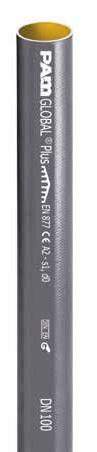
Recommended range for these applications: Plus range (see p.68)
The limitation between the S and Plus ranges is only determined by the type of fl uids and the operating temperature. However, the duration of daily exposure also directly
determines the appropriate range to select, hence why we called this chapter intensive or professional use. The combination of high pH products (base and alkaline products) and high temperatures systematically calls for the use of the Plus range.
With its anti-corrosion thick linings, the Plus range provides greater chemical resistance and is particularly well-suited to intensive uses.
• To transport effluents containing acids, bases or saline solutions at common operating temperatures, systematic use of the Plus range equipped with couplings with EPDM gaskets is recommended.
• For solvents, hot oil and where hydrocarbon traces may be present, the systematic use of the Plus range equipped with couplings with NBR gaskets is recommended.
Compulsory use of PLUS range + NBR gasket Solvents at common temperatures of use and hot oils
SOLVENTS (except Acetone)
Ethanol, methanol, glycol
Xylene
White Spirit
Gasoline, diesel, petroleum
Lubricants, petroleum derivates
High temperatures OILS
56 - PAM Building 03
range is compulsory
20° 60° 80°
Plus
pH
→
Compulsory use of PLUS range + EPDM gasket Acids and bases, saline solutions common temperatures of use
→ S Range is still possible
→ Plus range is compulsory
For uses not described or intensive industrial uses, please contact our technical support team:
tcbatiment.sgpam@saint-gobain.com
Tel: +33 (0)3 66 74 00 89
PAM Building - 57 03 WHY USE CAST IRON?
pH 20° 60° 80° WATER Salt water NaCI 30 g/l 5.6 Dermineralised water 6.6 Wastewater 6.9 DETERGENTS Cleaning supplies 10% 7.4 Phosphate-free washing liquid 7.7 Dishwasher cleaner 5% vol 9 Ammonia solution 10% 9.5 Pure ammonia solution 10 STAIN REMOVER/OXIDANTS “Ace Gentle” Type 5% 4.2 “Beckmann” Type tablet/5l 9.3 “Blanco” Type tablet/5l 10.3 MINERAL ACIDS Hydrochloric HCL 5% 1 Sulphuric H2SO4 10% 1 Sulphuric H2SO4 1% 2 Phosphoric H3PO4 10% 1.3 Phosphoric H3PO4 5% 1.8 Phosphoric H3PO4 2.5% 2 Nitric HNO3 10% 2 ORGANIC ACIDS Lactic 10% 1.1 Lactic 1-5% 2.2 Citric 5% 2 Vinegar 30% 2.9 Vinegar 10% 3.2 BASES Soda NaOH 12 Soda NaOH 13.6 Ammonia NH3 12.1 Potash KOH 13.6 Bleach 10% 12 Bleach 30% 12 Bleach 100% 12.5 SALTS KCL 3% 4.2 NaH2PO4 3% 4.2 (NH4) 2SO4 3% 6.7
CHEMICAL & CORROSION RESISTANCE
INTENSIVE USE: EXTERNAL STRESSES DUE TO AGGRESSIVE GROUND
Characterisation of external stresses
Below-ground wastewater drainage systems exposed to environmental stresses.
The buried section of a pipe may be laid in non-homogeneous ground or corrosive soil. When protected by galvanic e ect, the pipework can be installed without requiring systematic soil studies.
Recommended range for these applications: Plus range (see p.68)
Buried systems are subjected to ground loadings which can cause shearing strain on couplings. For these applications, it is therefore recommended to use wider couplings, and to use the “all stainless steel version” of the steel couplings to avoid corrosion due to the aggressiveness of the ground.
03
INTENSIVE USE: EXTERNAL STRESSES DUE TO CLIMATE EXPOSURES
Outdoor or facade exposures
Depending on the climatic conditions, while in operation outdoor wastewater and rainwater systems can be subjected to ultraviolet radiation, saline mist, condensation, freezing-thawing cycles and pollution.
The drainage systems must be fit for purpose despite exposure to adverse conditions.
Zinc coating improves the pipes’ ability to withstand climatic stresses and extends their service life.
Recommended range for these applications: Zn range (see p.70)
ZINC COATING

The zinc metal coating is an active protection provided by the galvanic action of a zinc-iron cell.
This action is two-fold:
• Formation of a stable protective layer of insoluble zinc salts
• Self-repairing of any damage

Zinc metalisation is an excellent corrosion inhibitor and is extremely effective at extending the lifespan of products subject to backfills or climatic stresses.

PAM Building - 59 03 WHY USE CAST IRON?
Zinc coated: a white line of zinc salt shows that the damage is completely plugged
Non-zinc coated: the damage is worsened and the corrosion (red marks) extends beyond the notch
Zinc spray
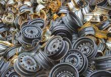
ENVIRONMENT CIRCULAR ECONOMY: RECYCLABILITY, AN EXCEPTIONAL ASSET OF CAST IRON
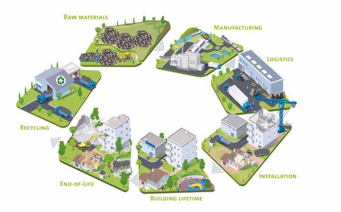
PAM BUILDING, A KEY PLAYER IN THE CIRCULAR ECONOMY
The preservation of natural resources is a major societal challenge, especially for the construction sector, which is a major consumer of raw materials and energy. PAM Building evacuation systems are a responsible and sustainable choice, respectful of natural resources and people.
A cast iron pipe gives our waste a second life
In order to contribute to the preservation of natural resources, PAM Building’s molten iron is produced by recycling cast iron and ferrous products. Unlike plastics, it can be completely and systematically recycled at the end of its life.
PAM Building’s drainage solutions can be recycled without any deterioration of their properties.
The product’s life cycle is also first-class in terms of environmentally-friendly logistics, longlasting functionality (up to 70 years without compromising the mechanical properties), low maintenance costs and commercially beneficial recycling.
100% recyclable indefinitely without losing any of its properties and made from 99% recycled content*
For the standard S range, recycled content is 99% with 11.5% pre-consumer** & 87.5% postconsumer*** according to ISO 14021: 1999.
Nothing is wasted: everything is recycled
Cast iron pipe systems are based on the principle of modular ranges of removable components. Their mechanical assemblies are reversible.
You can change your mind today or even tomorrow. When pipe systems are disassembled or modified, these components can be reused, which cuts down on waste dumping.
*Recycled content: proportion, by mass, of recycled material in a product or packaging. Only pre-consumer and postconsumer materials shall be considered recycled content.
** Pre-consumer material: material diverted from the waste stream during a manufacturing process. This excludes the reuse of materials such as rework, regrind, or scrap generated in a process and capable of being reclaimed within the same process that generated it.
*** Post-consumer material: material generated by households or commercial, industrial and institutional facilities in their role as end users of the product which can no longer be used for its intended purpose.
60 - PAM Building 03
DID YOU KNOW?
From waste recycled to fully recyclable products

99% 100% every year we recycle the equivalent of 18.000 cars on average.

Organised and numerous actors in the recycling channel
The recycling channel exists: collector network and recovery stream is existing and working!
We work with local supply for scrap (<125 km from the plant) to reduced economic and transport costs.
Following ISO 14021:1999 and LEED V4 criteria we can provide a recycled content declaration for our products.

PAM Building - 61 03 WHY USE CAST IRON?
ENVIRONMENT A TRANSPARENT APPROACH: SAFE PRODUCTS & LIFE CYCLE ASSESSMENT
Life Cycle Assessment: a rigorous tool for assessing the environmental impacts of our products
Understanding the environmental performances of construction products is a growing expectation for professionals in the building chain.
In PAM Building, we strongly believe that Life Cycle Assessment is the most reliable tool available to assess the green credentials of construction products and enables companies to communicate credible, fact-based information about their products to consumers. It is also a powerful tool for enhancing the environmental features of our products.LCA is a methodology based on specific standards ISO 14040 and ISO 14044:
• Multi-criteria tool: consumption of natural resources, air, ground and water emissions, waste generation, warming potential, …
• Multi-step tool: “cradle to gate” or “cradle to grave”.
62 - PAM Building 03
-
1 - CRADLE TO GATE 2
CRADLE TO GRAVE
Environmental Product Declaration
What is an Environmental Product Declaration?
The results of a LCA are presented in the formof an Environmental Product Declaration, locally administrated by program operators and based on ISO 25930 and EN 15804 standards. When an EPD has been checked by an independent third party, it is said to be verified. This process ensures the quality and reliability of the results: that is why we are committed to have verified EPDs.
We currently have produced and verified EPDs for our S and Plus ranges, both available on the Environdec platform : www.environdec.com

Overview of the EPD for our S range
This table enables a quick and synthetic overview of environmental footprint of the functional unit (1 m of SMU S cast iron pipe system for collection and drainage of waste water, sewage and rainwater in buildings), based on 70 years of lifetime.
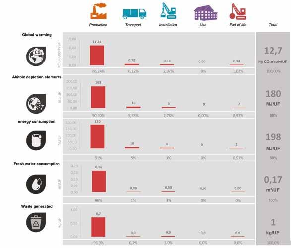
The complete EPD is available on the international Environdec platform, registration number S-P-02013.
> Source: https://www.environdec.com/Detail/?Epd=18393
PAM Building - 63 03 WHY USE CAST IRON?
01
WASTEWATER RAINWATER INFRASTRUCTURE EARTH-TO-AIR HEAT EXCHANGER COUPLINGS 66 72 76 78 80
04 OUR SOLUTIONS
WASTEWATER : DOMESTIC USE
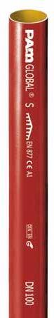
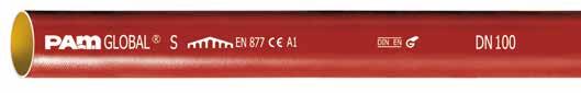
S RANGE (details on p.86)
DESCRIPTION:
Specialised range providing complete drainage solutions for transporting fluid waste and rainwater through buildings. High-quality cast iron pipes and fittings suitable for standard use applications. This range withstands di erent types of domestic e uents such as grey water, black water and rainwater.
RECOMMENDED USE:
First choice for commercial, public and residential buildings, particularly medium- to high-rise buildings which require robust and safe solutions for basements and lower levels to vertical risers. Some common applications are:
• O ces
• Shopping centers
• Housing
• Airports
• Hotels
• Public builidings
• Stadiums
MAJOR BENEFITS:
• Compliant with standard EN 877
• Performance guaranteed with marks delivered by a third party (NF, RAL-GEG, Kitemark, BBA, Sintef, Gost, Q+)
• High level of fire safety with excellent A1 reaction to fire (non-combustible) and fire resistance up to 240 minutes depending on the configuration (generally requires no special fire protection saving time and costs)
• Best acoustic comfort with Lsc,A < 10 dB (A) according to EN 14366
• Ease of installation due to the mechanical couplings assembled with simple tools
• Adaptable to all configurations with available accessories connecting cast iron with other materials
• Limited maintenance operations thanks to the technical and mechanical properties of cast iron
CHEMICAL AND CORROSION RESISTANCE:
• Hot water resistance: 24 h at 95°C
• Thermal cycle resistance: 1,500 cycles between 15°C and 93°C
• Chemical resistance for 2 ≤ pH ≤ 12
04
DIMENSIONS:
• Diameter: 50 to 400 mm (up to 600 mm on request)
• Length: 3,000 mm
ENVIRONMENTAL DATA:
• Recycled content: 99%
• 100% Recyclable
COATINGS:
• Pipes:
External coating: Red-brown, acrylic primer paint, average dry film thickness 40 μm. Cast-iron made with the De Lavaud process
Internal coating: Two-component ochrecoloured epoxy coating, average dry film thickness of 130 μm.
• Fittings: Externally and internally coated in red epoxy to an average thickness of 70 μm.

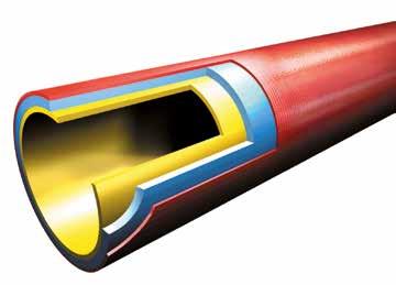

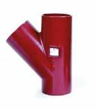
PRODUCT MARKING:
• Pipes:
Product name
Compliance with the RAL-GEG mark
Compliance with the DIN EN standard
• Fittings:
PAM Building - 67 04 OUR SOLUTIONS
CE marking / Reaction to fire classification
Pipe size
Standard conformity
WASTEWATER: INTENSIVE USE
PLUS RANGE (details on p.108)
DESCRIPTION:
High-performance cast iron pipes and fittings designed to withstand intensive use. Smartly designed to drain wastewater in above- and below-ground applications when exposed to hot and/or aggressive discharge. When installed below ground in aggressive environments it is highly resistant to external stresses.
RECOMMENDED USE:
The Plus range is the first choice for hospitals, laboratories and collective kitchens.
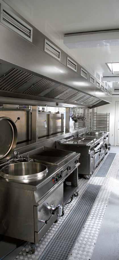
MAJOR BENEFITS:
• Compliant with standard EN 877
• Performance guaranteed with marks delivered by a third party (NF, RAL-GEG, Kitemark, BBA, Sintef, Gost, Q+)
• Long-lasting operational safety thanks to the robustness and sti ness (around 700 kN.m) of cast iron and the use of flexible mechanical couplings
• High level of fire safety with excellent A2, s1-d0 reaction to fire and fire resistance up to 240 minutes depending on the configuration (generally requires no special fire protection, saving time and costs)
• Best acoustic comfort with Lsc,A < 10 dB (A) according to EN 14366
• Ease of installation due to mechanical couplings assembled with simple tools
CHEMICAL AND CORROSION RESISTANCE:
• Hot water resistance: 24 h at 95°C
• Thermal cycle resistance: 1500 cycles between 15°C and 93°C
• Chemical resistance for 2 ≤ pH ≤ 13, up to 80°C (check resistance for more than 30 di erent e uents in the tables on p.56 and 57)
• External coating corrosion resistance test to neutral salt spray according to standard NF-EN ISO 9227_2017: 2500 hours
DIMENSIONS:
• Diameter: 50 to 400 mm (up to 600 mm on request)
• Length: 3000 mm
04
ENVIRONMENTAL DATA:
• Recycled content: 99%
• 100% Recyclable
COATINGS:
• Pipes:
External coating: Grey, acrylic primer paint, average dry film thickness of 40 μm.
Anti-corrosive zinc coating of 130 g/m2
Cast-iron made with the De Lavaud process
Internal coating: Two-component ochre-coloured epoxy coating applied in two layers, average dry film thickness of 250 μm.
• Fittings:
Externally and internally coated with a grey powder epoxy to an average thickness of 300 μm.
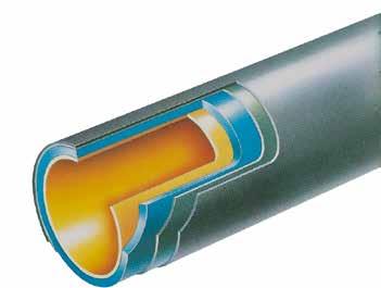


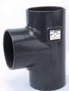
PRODUCT MARKING:
• Pipes:
Product name
Compliance with the RAL-GEG mark
Standard
• Fittings:
PAM Building - 69 04 OUR SOLUTIONS
CE marking / Reaction to fire classification Pipe size
Compliance with the DIN EN standard conformity
WASTEWATER: INTENSIVE USE
ZN RANGE (details on p.120)
DESCRIPTION:
High-performance cast iron pipes designed to withstand external stresses due to climate exposures (ultraviolet radiation, saline mist, condensation, freezing-thawing cycles and pollution)
RECOMMENDED USE:
The Zn range cast iron drainage system is recommended for applications in coastal areas, directly or indirectly exposed to climatic stresses and/or polluted atmospheres, polluted or confined atmospheres such as cellars, crawl spaces or those which may be exposed to external aggressions during manufacturing processes and condensation.
MAJOR BENEFITS:
• Compliant with standard EN 877
• Performance guaranteed with marks delivered by a third party (NF, Watermark)
• Resistance to climatic stresses thanks to the zinc coating, withstanding extended exposure to ultraviolet light or wide temperature variations

• High level of fire safety with excellent A2, s1-d0 reaction to fire and fire resistance up to 240 minutes depending on the configuration (generally requires no special fire protection, saving time and costs)
• Best acoustic comfort with Lsc,A < 10 dB (A) according to EN 14366
• Ease of installation due to mechanical couplings assembled with simple tools
CHEMICAL AND CORROSION RESISTANCE:
• Hot water resistance: 24 h at 95°C
• Thermal cycle resistance: 1500 cycles between 15°C and 93°C
• Chemical resistance for 2 ≤ pH ≤ 12
• External coating corrosion resistance test to neutral salt spray according to standard NF-EN ISO 9227_2017: 3500 hours
04
DIMENSIONS:
• Diameter: 50 to 400 mm (up to 600 mm on request)
• Length: 3000 mm
ENVIRONMENTAL DATA:
• Recycled content: 99%
• 100% Recyclable COATINGS:
• Pipes:
External coating: red-brown, acrylic primer paint, average dry film thickness of 40 μm.
Anti-corrosive layer: flame-applied zinc metal coating of 260 g/m2 on average
Cast-iron made with the De Lavaud process
Internal coating: two-component ochre-coloured epoxy coating, average dry film thickness of 130 μm.
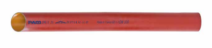
• Fittings: Please contact us for details of the fittings to be used with the Zn range pipes
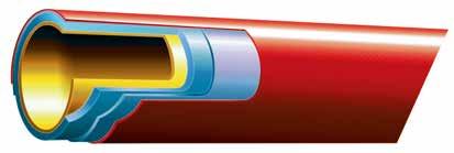
PRODUCT MARKING:
• Pipes:
PAM Building - 71 04 OUR SOLUTIONS
Pipe size Compliance with the NF standard Standard conformity
CE marking / Reaction to fire classification
Product name
Country of origin
RAINWATER: GRAVITY SYSTEMS
RESIDENTIAL (TYPE R) (details on p.122)

MAJOR BENEFITS:
• Compliant with standard EN 12056-3
• Additional value to buildings due to the round or fluted aesthetic appearance of the Residential drainage solution
• Low maintenance due to the best in class resistance to shocks and crushing
• Long lifetime with high resistance to climatic stresses due to the zinc coating and the low thermal expansion coe cient of cast iron
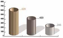
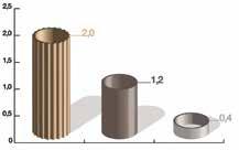
• High level of fire safety with excellent A1 reaction to fire (non-combustible)
• Ease of installation due to the push-fit assembly system
MECHANICAL RESISTANCE:
• Shock resistance:
The test consists of dropping a mass of 2.75 kg on a descent at increasing heights until it breaks or cracks.
The average height of the fall for Residential (Type R) is 2 to 5 times higher than for other products. Up to an average drop height of 2 m, the Residential (Type R) deforms while the other products have cracked.
• Crushing resistance:
04
Drop height (in m) Other cast iron maxi. Other cast iron mini. Residential (Type R) PAM Building Other cast iron maxi. Other cast iron mini. Residential (Type R) PAM Building In MPa
DIMENSIONS:
• Diameter: 75 – 100 – 125 mm
• Length: 1000 and 2000 mm
ENVIRONMENTAL DATA:
• Recycled content: 99%
• 100% Recyclable
COATINGS:
• Pipes:
External coating: light beige colour (RAL 7032), water-based coating of 40 μm.
Anti-corrosive layer: flame-applied zinc metal coating of 130 g/m2 in average
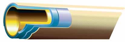
Cast-iron made with the De Lavaud process
Internal coating: water-based coating of 40 μm.
• Fittings: Cataphoresis 70 μm + water-based coating 60 μm.
PAM Building - 73 04 OUR SOLUTIONS
round
RAINWATER: SIPHONIC SYSTEM
EPAMS® (details on p.126)
HOW IT WORKS?
The EPAMS® system is a combination of cast iron pipes, fittings and accessories, jointed with PAM Rapid couplings or couplings able to withstand a negative pressure of -700 mbar.
EPAMS outlets are equipped with an anti-vortex mechanism that prevents air from entering the pipes at rainwater inlets. The absence of air then causes an acceleration of the flow by creating a negative pressure.
MAJOR BENEFITS:
• System under French Technical Approval EPAMS® 5.2/14-2386_V2
• Suitable for all ambitious architecture and all roof types*

• Cost-e ciency via savings on purchases and installation costs: fewer downpipes than gravity systems
• Suitable for all areas and rainfall: high volumes of water drained up to 75 l/s per outlet

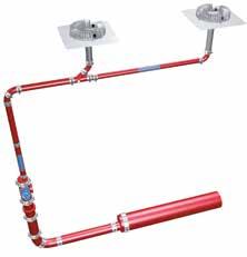
• Low and easy maintenance with a durable system: no claim since its launch (1994)
TECHNICAL SUPPORT:
• Technical study and network sizing provided by PAM Building through the dedicated EPAMS® software
• 2D and 3D design available
• Job site inspection
INSTALLATION:
• See p.178
*For more details please consult French Technical Approval EPAMS 5.2/14-2386_V2 or contact us: tcbatiment.sgpam@saint-gobain.com
74 - PAM Building 04
EPAMS®
DIMENSIONS:
• Diameters : 50 – 75 – 100 – 125
PRODUCT RANGE:
• EPAMS® outlet to be welded
Application field: This roof outlet is especially designed to be welded (or brazed) in gutters or metal roof valleys.
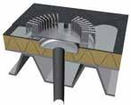
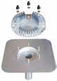
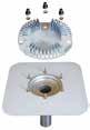
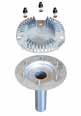
• EPAMS® outlet with flange
Application field: This roof outlet can be used for roofs containing extra-thick metal gutters or valleys as well as for roofs waterproofed by synthetic membranes.
• EPAMS® outlet with steel plate
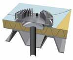
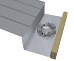
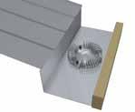
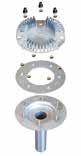
Application field: This roof outlet is used on all the roofs mentioned within the scope of the French Technical Assessment 5+14/14-2386, except those with waterproofing by a synthetic membrane.
• EPAMS® outlet for flexible PVC membrane
Application field: This roof outlet is used on non-accessible roofs and/or with equipment zones, and waterproofed by synthetic PVC-P membranes depending on the manufacturer’s technical assessment. Waterproofing is provided by a weld between the various PVC elements to seal them in a traditional way. The membrane may be visible or may be given heavy mineral protection. For the latter case, it is possible to use gravel > 15 mm, but the roof outlet must be fitted with an elevating kit for the anti-vortex mechanism.
PAM Building - 75 04 OUR SOLUTIONS
INFRASTRUCTURE
ITINERO® (details on p.128)
DESCRIPTION:
The Itinero® range is a solution that meets the high drainage technical demands of infrastructure projects.
Itinero® is a dedicated range which factors in the specificities of a project and guarantees excellent performance to accommodate di erent stress levels (weather constraints or exposures).
RECOMMENDED USE:
It is recommended for collecting and draining surface water from bridges, tunnels and viaducts, for new builds or renovation projects.
MAJOR BENEFITS:
• Compliant with standard EN 877
• Performance guaranteed with marks delivered by a third party (NF)
• Long lifetime with high resistance to climatic stresses due to the zinc coating and low thermal expansion coe cient of cast iron
• Low maintenance due to the best in class resistance to shocks and crushing
• High level of fire safety with excellent A2,s1-d0 reaction to fire (non-combustible)
• Suitable for many bridge and tunnel designs and adapted to renovation projects
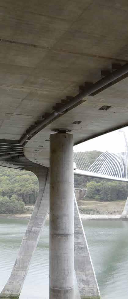
• Easy to install due to mechanical couplings assembled with simple tools
TECHNICAL SUPPORT :
• We provide design recommendations, discharge system set-up and a bill of quantities for your project. Contact us at: tcbatiment.sgpam@saint-gobain.com
CHEMICAL AND CORROSION RESISTANCE:
• Hot water resistance: 24 h at 95°C
• Thermal cycle resistance: 1,500 cycles between 15°C and 93°C
• Chemical resistance for 2 ≤ pH ≤ 12
• External coating corrosion resistance test to neutral salt spray according to standard NF-EN ISO 9227_2017: 4500 hours
04
DIMENSIONS:
• Diameter: 100 to 600 mm
• Length: 3000 mm
ENVIRONMENTAL DATA:
• Recycled content: 99%
• 100% Recyclable
COATINGS:
• Pipes:
External coating: Grey (approximate RAL 7030), epoxy coating, average dry film thickness of 80 μm
Anti-corrosive zinc coating of 260 g/m (about 40 μm)
Cast-iron made with the De Lavaud process
Internal coating: epoxy coating, average dry film thickness of 130 μm.
• Fittings: Externally and internally coated with a mat grey powder epoxy (approximate RAL 7030), to an average thickness of 300 μm
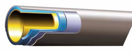
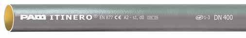
PRODUCT MARKING:
• Pipes:
Pipe
Standard conformity
Compliance with the DIN EN standard
• Fittings:
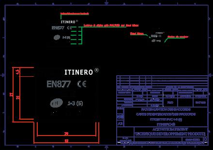
PAM Building - 77 04 OUR SOLUTIONS
name CE marking / Reaction to fire classification
Product
Compliance with the NF standard size
EARTH-TO-AIR HEAT EXCHANGER
ELIXAIR® RANGE available on request
HOW IT WORKS?
An earth-to-air heat exchanger (EAHX) is a surface geothermal solution for buildings, involving a buried pipe system which circulates fresh air.
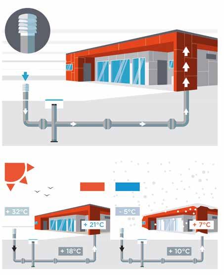
It aims to warm up fresh air in buildings in winter and cool it down in summer. Based on thermal air-to-ground exchanges, it is a passive solution. Where installed, the earth-to-air heat exchanger plays an active role in the building’s thermal comfort.
ELIXAIR® by PAM is a comprehensive o er, designed to build earth-to-air heat exchangers combining safety and e ciency with ductile iron products.
A ventilation system di use the temperate air inside the building
In summer, the Elixair® system cools the air
In winter the Elixair® system heats the air
78 - PAM Building 04
Through the ductile iron pipes, the soil (temperature between 10°C and 18°C) regulates the air temperature
The air enters into the system
Manhole for condensates
+32°C -5°C
RECOMMENDED USE:
• Public buildings
• Commercial and industrial buildings
• Farm buildings
MAJOR BENEFITS:
• System under French Technical Approval 14.5/14-2056_V1
CSTB
• Energy savings thanks to the complete system and the high thermalconductivity of ductile iron
• Resistance to ground loading and tra c: ductile iron pipe systems can be buried deep without damage, also under areas which are driven over or car parks

• Withstands rustic laying conditions allowing backfill with the extracted materials
• Excellent air tightness due to Express or Standard couplings working under compression
• Durability: as for all buried systems, strength and longlasting properties are key factors to avoiding premature replacements
THERMAL PERFORMANCES:
• In winter: in-out average temperature di erence = 7 to 12°C
• In summer: in-out average temperature di erence = 7 to 16°C
TECHNICAL SUPPORT:
Send us your project and we will be able to help you with the supply of:
• Your earth-to-air heat exchanger
• The bill of quantities
• The heat energy saved in winter
• The cooling energy saved in summer
PAM Building - 79 04 OUR SOLUTIONS
Contact us: tcbatiment.sgpam@saint-gobain.com Tel: +33 (0)3 66 74 00 89
COUPLINGS
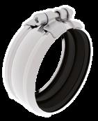
COUPLINGS MAIN FEATURES
A coupling is made of several components: casing, screws, barrel and gasket as described in the drawing.
SEVERAL GRADES OF STEEL
We follow a global material designation* for steel components of the coupling described in the following table.
*Please refer to datasheet for specific information as some material may differ depending on the coupling design.
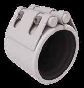
80 - PAM Building 04
1 3 4 2 1 2 4
Screw and nut Coated steel class 8.8 Barrels 1.4510 430Ti Casing or strap 1.4510 430Ti Screw 1.4404 316L Barrels 1.4401 316 Casing or strap 1.4301 304 Screw 1.4404 316L Barrels 1.4401 316 Casing or strap 1.4404 316L W2 W4 W5 DIN AISI
Screw and nut Casing Barrel Gasket 1 3 4 2
ELASTOMERIC GASKETS
The choice of the elastomeric gasket is related to the nature of the effluent.
EPDM: EPDM rubber is suitable for most types of effluents.
NBR: Nitrile Butadiene Rubber is recommended for wastewater and runoff water liable to contain hot oil, solvents or hydrocarbons. They are recommended for infrastructure applications.
COUPLING SELECTION GUIDE
PAM Building - 81 04 OUR SOLUTIONS
B 2 3 A 1 4 2
Type of e uent Aerial network In concrete External stresses* Burried network Infrastructure Wastewater S range Zn range Itinero® Rainwater Agressive e uents Plus range Plus range Hydrocarbon runo water Plus range Itinero® 1 2 3 4 W2 W4 EPDM W2 W4 EPDM A W5 EPDM EPDM EPDM W5 W5 W2 W4 NBR W5 NBR B
TYPE OF NETWORK
*ie. Climate exposure; pollution, sea-side
COUPLINGS
(details on p.132)
We provide a large range of couplings to match all building specifications. Our products are available in di erent versions to withstand all types of e uents, pressures and external stresses.
STANDARD COUPLINGS
The single-bolt PAM Rapid coupling allows fast and reliable installation. It ensures optimized watertightness, pressure and corrosion resistance.
MAJOR BENEFITS:
• Compliant with standard EN 877
• Ease of installation
• Suitable for projects with effluents containing solvents, hydrocarbons (i.e. car parks), due to the availability of the NBR version (nitrile gasket)
MATERIAL:
• Main material: W2 or W5 (AISI 316L)
• Gasket: EPDM or NBR
PRESSURE RESISTANCE:
• Exceeds the EN 877 requirements – DN 50 to 125: 10 bar / DN 150 to 200: 5 bar / DN 250 to 300: 3 bar
“R” for Repair: this coupling is particularly suited to repairs and retrofits. It is installed in two separate parts.
MAJOR BENEFITS:
• Compliant with standard EN 877
• Full opening strap particularly suited to renovation projects
MATERIAL:
• Main material: W5 (AISI 316L)
• Gasket: EPDM
PRESSURE RESISTANCE:
• Exceeds the EN 877 requirements – DN 50 to 125: 10 bar / DN 150 to 200: 5 bar
82 - PAM Building 04
PAM Rapid (p.132)
PAM R (p.133)
HIGH PRESSURE COUPLINGS
PAM HP FLEX coupling (p.134)
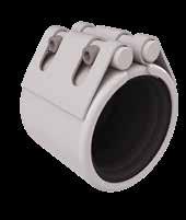
PAM HP GRIP coupling (p.135)
PAM HP FLEX couplings withstand up to 10 bar of hydrostatic pressure for most diameters. These couplings are used for straight runs where the pressures can occur.
MAJOR BENEFITS:
• Compliant with standard EN 877
• The solution for large-diameter networks (>300 mm)
MATERIAL:
• Main material: W4 (AISI 304) or W5 (AISI 316L)
• Gasket: EPDM or NBR
PRESSURE RESISTANCE:
• Exceeds the EN 877 requirements –DN 100 to 400: 10 bar / DN 500 and DN 600: 6 bar
In sections where end thrust e orts have to be addressed, the autogrip couplings are alternative solutions for securing junctions whilst addressing pressure. The PAM HP GRIP couplings are self-anchored couplings with built-in claw rings.
MAJOR BENEFITS:
• Compliant with standard EN 877
• The 2-in-1 solution: coupling and grip collar with only one product
• Particularly suited to EPAMS® installation
MATERIAL:
• Main material: W4 (AISI 304) or W5 (AISI 316L)
• Gasket: EPDM or NBR
PRESSURE RESISTANCE:
• Exceeds the EN 877 requirements –DN 100 to 400: 10 bar / DN 500 and DN 600: 6 bar
PAM Building - 83 04 OUR SOLUTIONS
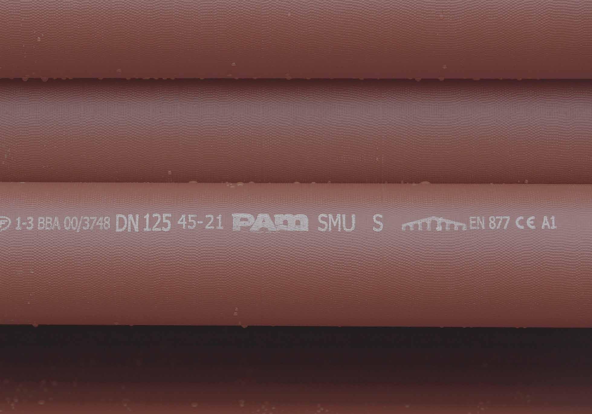
WASTEWATER
› Domestic use: P AM-GLOBAL® S
› Intensive use: PAM-GLOBAL® Plus, SMU Zn
RAINWATER
› Gravity systems: Residential (Type R)
› Siphonic systems: EPAMS®
INFRASTRUCTURE
› Itinero®
05 PRODUCT
86 122 128 132 140 144
CATALOG
COUPLINGS, COLLARS & CONNECTORS SUPPORTING & FIXING SYSTEMS ACCESSORIES
DOMESTIC USE - PAM-GLOBAL® S
PAM-GLOBAL® S - PIPES
* For dimensions over DN 400 please contact us.
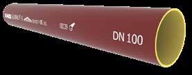

PAM-GLOBAL® S - FITTINGS
BENDS I Short radius bends
86 - PAM Building 05
L H W
a a L q H W a a L q H W
DN L H W Weight Product code 50 3000 58 58 12.9 156361 75 3000 83 83 18.8 156550 100 3000 110 110 25.1 156561 125 3000 135 135 35.3 156734 150 3000 160 160 42.1 156825 200 3000 210 210 69.1 156949 250 3000 274 274 99.5 157048 300 3000 326 326 129.4 157113 400 3000 429 429 179.5 157171
DN L H W a q Weight Product code 50 66 80 58 40 66 0.4 155752 75 93 99 83 45 78 0.68 176702 100 121 112 110 50 83 1 155816 125 148 134 135 60 99 1.7 155870 150 173 148 160 65 108 2.5 155903 200 227 184 210 80 129 4.6 155932
WASTEWATER
15° Bends
“All dimensions are in mm and nominal weights are in kg”
BENDS I Short radius bends
* For dimensions over DN 400 please contact us.


PAM Building - 87 05 PRODUCT CATALOG
a a L q H W a a L q H W a a L q H W a a L q H W a a L q H W
22° Bends DN L H W a q Weight Product code 50 70 88 58 40 66 0.45 156388 75 97 105 83 47 74 0.8 156480 100 126 125 110 54 84 1.3 156598 125 152 143 135 61 92 1.9 156761 150 179 162 160 69 102 2.6 156855 200 233 200 210 83 122 4.4 156974 250 300 240 274 100 138 9.5 157071 30° Bends DN L H W a q Weight Product code 50 76 97 58 45 69 0.5 155753 75 102 114 83 50 73 0.8 176703 100 132 136 110 60 81 1.3 155817 125 160 164 135 70 96 2 155871 150 189 188 160 80 108 3 155904 200 243 229 210 95 124 5.4 155933 250 309 270 274 110 133 9.7 155948 300 367 322 326 130 159 15.5 155960 400 478 369 429 184 173 26 170731 45° Bends DN L H W a q Weight Product code 50 84 106 58 50 65 0.6 155751 75 112 132 83 60 73 0.9 176704 100 142 158 110 70 80 1.6 155815 125 171 184 135 80 89 2.1 155869 150 199 210 160 90 97 3.2 155902 200 256 262 210 110 113 5.3 155931 250 324 319 274 130 125 10 155947 300 387 380 326 155 149 18.3 155959 400 540 573 429 247 270 34.4 157175 a a L q H W “All dimensions are in mm and nominal weights are in kg”
WASTEWATER
DOMESTIC USE - PAM-GLOBAL® S

BENDS I Short radius bends

88 - PAM Building 05 a a L q H W a a L q H W 68° Bends DN L H W a q Weight Product code 50 104 123 58 65 70 0.8 155750 75 131 149 83 80 72 1 176705 100 159 176 110 90 74 1.8 155814 125 188 205 135 105 80 3 155868 150 219 237 160 120 89 4.1 155901 88° Bends DN L H W a q Weight Product code 50 104 107 58 75 49 0.8 155749 75 138 140 83 95 57 1.4 176706 100 166 169 110 110 59 2.2 155813 125 194 197 135 125 62 2.9 155867 150 227 230 160 145 70 4.3 155900 200 288 291 210 180 81 8.1 155930 250 360 363 274 223 89 13.5 157065 300 427 431 326 280 105 27.7 157130 400 644 651 429 466 223 59 245567
“All dimensions are in mm and nominal weights are in kg”
BENDS I Long radius bends

BENDS I Long tail bends
PAM Building - 89 05 PRODUCT CATALOG a a H W L b a b o q H L W H L o p p W
88° Bends DN L H W a b Weight Product code 100 324 324 110 269 230 4.2 156606 150 349 349 160 274 210 8 156860 135° Bends DN L H W o p Weight Product code 100 314 272 110 236 100 4.5 155818 45° Bends DN L H W a b o q Weight Product code 100 338 143 110 250 250 180 260 3.5 155824 a b o q H L W “All dimensions are in mm and nominal weights are in kg - “Hatch patterned area in the drawings shows the max. cutting length”.
WASTEWATER
DOMESTIC USE - PAM-GLOBAL® S

BENDS I Long tail bends
BENDS I 88° Double bends
90 - PAM Building 05
L H o a a c b b W L H o a a c b b W a b o L H q W a b o L H q W
88° Bends DN L H W a b o q Weight Product code 100 305 165 110 110 250 140 195 3.7 155823
DN L H W a b c o Weight Product code 50 148 148 58 121 50 100 148 1 155754 75 183 183 83 145 60 120 183 1.5 176707 100 228 228 110 170 70 140 228 2.8 155819 125 265 265 135 195 80 160 265 4.4 155872 150 303 303 160 219 90 180 303 6.3 155905 “All dimensions are in mm and nominal weights are in kg” - “Hatch patterned area in the drawings shows the max. cutting length”.
BENDS I 88° Long tail double bends

BENDS I Offsets
BENDS I 88° Vented bends
PAM Building - 91 05 PRODUCT CATALOG
b b a a L H W c b b a a L H W c
H b c c L W
p r r H L q W r r p H q L W Axial Radial DN L H W a b c Weight Product code 75 315 315 83 273 60 301 2.9 179679 100 346 346 110 291 70 312 4.8 155820 125 376 376 135 308 80 322 6.1 155873 150 406 406 160 326 90 334 9.0 155906 DN L H W b c Weight Product code 100 175 205 110 65 70 2 155812 240 270 110 130 70 3.7 155821 DN Ventilation L H W p q r Weight Product code 100 Radial (dn 50) 166 169 150 95 59 110 2.15 157581 100 Axial (dn 50) 200 169 110 166 59 110 2.15 156585 “All dimensions are in mm and nominal weights are in kg”
WASTEWATER
DOMESTIC USE - PAM-GLOBAL® S
BRANCHES I Single branches
* For dimensions over DN 400 please contact us.
“All dimensions are in mm and nominal weights are in kg”
92 - PAM Building 05
H b o c L p q r W
45° Branches DN dn L H W b c o p q r Weight Product code 50 50 144 185 58 135 135 50 165 124 36 1.34 155769 75 50 156 180 83 135 135 45 161 120 43 1.6 173786 75 179 215 83 155 155 60 198 140 40 2.2 173787 100 50 191 200 110 165 165 35 172 131 47 2.4 155828 75 214 235 110 170 170 50 209 151 46 3.2 173788 100 238 275 110 205 20 70 253 175 45 4 155857 125 50 218 205 135 185 185 20 170 130 44 3.2 155877 75 237 240 135 195 200 45 215 156 51 4.2 176716 100 261 280 135 220 220 60 245 177 47 5 155882 125 284 320 135 240 240 80 296 201 49 5.2 155895 150 75 265 255 160 210 220 35 220 161 54 5.1 176733 100 287 295 160 240 240 55 262 185 54 5.8 155912 125 307 325 160 255 255 70 298 202 52 7.4 155914 150 323 355 160 265 265 90 333 219 53 7.9 155926 200 75 303 260 210 240 240 20 218 159 64 7.4 176734 100 340 310 210 265 265 40 275 198 67 9.3 155935 125 360 340 210 280 280 55 310 215 64 11.6 155936 150 383 375 210 300 300 75 353 240 66 12.3 155937 200 418 455 210 340 340 115 428 280 68 17.1 155944 250 100 398 330 274 315 315 15 276 198 72 13.6 155949 125 420 370 274 335 335 35 318 223 75 17.8 155950 150 440 405 274 350 350 55 358 245 75 22 155951 200 486 480 274 390 390 90 440 291 75 22.4 155952 250 537 580 274 430 430 130 530 335 70 29 155956 300 100 445 350 326 345 345 5 287 208 88 18.9 155961 125 464 360 326 360 360 15 316 221 80 22.7 155962 150 487 415 326 380 380 35 359 246 81 28 155963 200 547 485 326 415 440 70 454 305 81 31 155964 250 588 580 326 465 465 115 540 347 80 37.6 155965 300 634 660 326 505 505 155 661 431 115 46.3 155968 400 300 728 660 429 555 555 105 620 389 86 56.4 157178 400 820 835 429 645 645 190 795 492 101 98 15785
PAM Building - 93 05 PRODUCT CATALOG H b o c L p q r W H b o c L p q r W 68° Branches DN dn L H W b c o p q r Weight Product code 50 50 118 145 58 80 80 55 117 65 37 1 156433 75 75 158 180 83 110 110 70 149 72 37 2 156542 100 100 195 220 110 130 130 85 189 87 50 2.8 155856 125 125 235 255 135 155 155 100 220 95 50 4.5 156811 150 150 276 295 160 180 180 115 256 108 55 6.5 156929 200 200 352 365 210 225 225 140 321 125 63 12 1557027 88° Branches DN dn L H W b c o p q r Weight Product code 50 50 110 145 58 66 80 79 111 53 31 1 155767 75 50 132 160 83 75 90 85 117 59 42 1.5 176718 75 138 180 83 85 95 95 140 57 37 1.6 176719 100 50 161 170 110 76 105 94 127 69 45 2 155827 75 166 190 110 90 110 100 145 62 40 2.4 176720 100 172 220 110 105 115 115 174 64 41 2.8 155855 125 50 188 180 135 82 120 98 131 73 51 2.6 155876 75 194 205 135 100 125 105 151 68 48 2.9 176722 100 199 235 135 110 130 125 184 74 48 4.2 155880 125 205 260 135 123 135 137 209 74 48 5 155894 150 50 221 200 160 100 140 100 134 76 51 3.9 155908 75 221 220 160 105 140 115 161 78 55 4.4 176723 100 227 245 160 115 145 130 190 80 52 5.6 155911 125 232 275 160 128 150 147 220 85 56 6.1 155913 150 237 300 160 142 155 158 243 83 55 6.7 156925 200 100 282 270 210 125 175 145 206 96 64 8.8 156980 200 388 365 210 172 183 193 296 86 67 11 157024 250 250 366 455 274 228 243 240 375 101 77 19.5 157102 300 300 434 530 326 265 265 265 437 111 87 35 157165 400 400 616 684 429 314 370 370 595 165 90 67 170732 “All dimensions are in mm and nominal weights are in kg”
WASTEWATER
DOMESTIC USE - PAM-GLOBAL® S
94 - PAM Building 05 BRANCHES I Long tail single branches H b c d e L p q r W H b c d e L p q W H b d c e r q p L W H b d c e r q p L W H b d c e L q p W H b d c e L q p r W
45° Branches DN dn L H W b c d e p q r Weight Product code 100 100 238 430 110 205 205 225 170 424 346 241 5.3 156723 68° Branches DN dn L H W b c d e p q r Weight Product code 100 100 195 460 110 130 130 330 250 430 328 290 4.8 156721 88° Branches DN dn L H W b c d e p q r Weight Product code 100 100 177 430 110 105 115 325 210 274 269 254 4.7 155861 “All dimensions are in mm and nominal weights are in kg” - “Hatch patterned area in the drawings shows the max. cutting length”.


PAM Building - 95 05 PRODUCT CATALOG H b c L p q r d W BRANCHES
Double branches H b c d L p q r W H b c d L p q r W 45° Branches DN dn L H W b c d p q r Weight Product code 100 100 346 260 110 190 190 70 243 165 46 5.3 156709 125 100 387 280 135 220 220 60 254 177 50 6.3 257729 125 421 305 135 240 240 65 285 190 45 7.9 156817 150 100 394 280 160 225 225 55 252 174 54 7.3 156865* 150 488 355 160 265 265 90 334 277 55 11.8 156936 68° Branches DN dn L H W b c d p q r Weight Product code 50 50 178 145 58 85 85 60 118 64 35 1.2 156437 75 75 234 180 83 110 110 70 149 72 36 2.3 156546 100 100 281 220 110 130 130 85 189 87 50 3.4 156707 125 125 336 255 135 155 155 100 220 95 51 5.5 156815 150 150 392 295 160 180 180 115 256 108 557 8.2 156934 88° Branches DN dn L H W b c d p q r Weight Product code 100 50 212 170 110 76 105 94 127 69 45 2.2 155825 75 220 190 110 90 110 100 145 62 40 2.7 179685 100 243 230 110 105 120 115 179 69 49 3.7 155858 125 100 263 235 135 115 135 130 184 74 48 4.5 155874 150 100 294 245 160 115 145 130 190 80 52 5.9 155907 Short double branches “All dimensions are in mm and nominal weights are in kg” * Availability: contact us H b c L p q r d W H b c d L p q r W H b c d L p q r W
I
WASTEWATER
DOMESTIC USE - PAM-GLOBAL® S
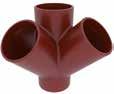
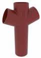
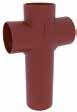
Long tail double branches
Corner branchesShort corner branches
96 - PAM Building 05 H b L p q d W H b L c p d W H b L c p d W H c b d L p q r W H c b d L p q r W H b c L p q d W
68° Branches DN dn L H W b c d p q r Weight Product code 100 100 280 414 110 130 130 284 244 281 383 6.3 176896 88° Branches DN dn L H W b c d p q r Weight Product code 100 100 243 405 110 110 120 295 222 244 354 5.9 176883 45° Branches DN dn L H W b c d p q r Weight Product code 100 100 227 260 227 190 190 70 242 166 46 5.2 156716
“All dimensions are in mm and nominal weights are in kg” - “Hatch patterned area in the drawings shows the max. cutting length”. H b c L p d W
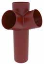
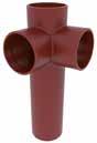
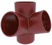
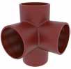
PAM Building - 97 05 PRODUCT CATALOG c H b L q p d W c r H b L q p d W H c b d L p q W H c b d L p q r W Corner branchesLong tail corner branches H b d c L p q r W H b d c L p q r W H b d c L p q r W H b d c L p q W 68° Branches DN dn L H W b c d p q r Weight Product code 75 75 158 180 158 110 110 70 149 72 36 2.1 156548 100 100 195 220 195 130 130 90 189 87 50 3.5 156714 68° Branches DN dn L H W b c d p q r Weight Product code 100 100 195 414 195 130 130 284 383 244 281 5.1 176943 88° Branches DN dn L H W b c d p q r Weight Product code 100 100 177 430 177 105 115 325 379 244 269 5.3 155862 88° Branches DN dn L H W b c d p q r Weight Product code 75 75 137 180 136 85 95 95 140 57 36 2 179682 100 75 165 190 165 90 110 100 145 62 40 2.8 179683 100 177 230 177 105 120 115 179 69 44 2.8 155860 125 100 199 235 199 110 130 125 184 74 48 4.3 155889 150 100 227 245 227 115 145 130 190 80 52 5.3 155919 “All dimensions are in mm and nominal weights are in kg” - “Hatch patterned area in the drawings shows the max. cutting length”.
WASTEWATER
DOMESTIC USE - PAM-GLOBAL® S
BRANCHES I
Single long arm branches
TAPERED PIPES I Reducers

* For dimensions over DN 400 please contact us.
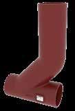
98 - PAM Building 05
H b L W c d
DN dn L H W b c d Weight Product code 75 50 83 80 83 47 30 13 0.65 176727 100 50 110 80 110 45 30 26 0.9 155764 75 110 90 110 45 35 14 1 176728 125 50 135 85 135 50 30 39 1.5 155765 75 135 95 135 52 35 26 1.3 176730 100 135 95 135 50 40 13 1.6 155842 150 50 160 95 160 55 30 51 1.9 155766 75 160 100 160 57 35 39 1.9 176732 100 160 105 160 60 40 25 2 155843 125 160 110 160 60 45 13 2 155892 200 100 210 115 210 70 40 50 3.6 155844 125 210 120 210 70 45 38 3.8 155893 150 210 125 210 65 50 25 3.4 155922 250 100 274 125 274 82 45 82 6 156690 150 274 135 274 82 50 57 6.3 155923 200 274 145 274 80 60 32 6.9 155942 300 150 326 150 326 97 50 83 11 155924 200 326 160 326 95 60 58 10.2 155943 250 326 170 326 95 70 26 10.7 155955 400 300 429 200 429 100 100 52 19.6 157163
H a c p L W DN dn L H W a c p Weight Product code 100 100 282 450 110 260 70 340 6 156726 “All dimensions are in mm and nominal weights are in kg”
ACCESS FITTINGS I Access pipes
ACCESS FITTINGS I Blank ends
ACCESS FITTINGS I Expansion plugs
See p.151 for information on resistance to accidental pressure. Expansion plugs with bleeding valve are available on request for DN 125/DN 150 and DN 200 (for watertightness tests).
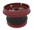

PAM Building - 99 05 PRODUCT CATALOG L H I D O D W
H L W H o L W H o L W
Round door DN L H W ID OD Weight Number of bolts Product code 50 105 190 93 53 105 2.3 2 179191 75 134 220 115 78 134 3.2 2 179647 100 159 260 139 104 159 5 2 179192 125 202 280 202 152 202 7.0 3 280010 150 243 320 226 180 243 9.8 4 280012 200 243 360 277 180 243 12.9 4 280013 250 274 380 362 180 243 18.7 4 280014 300 326 400 413 180 243 25 4 280015 DN L H W Weight Product code 50 58 30 58 0.25 155747 75 83 35 83 0.45 176700 100 110 40 110 0.8 155809 125 135 45 135 1.2 155865 150 160 50 160 1.7 155898 200 210 60 210 3.2 155928 250 274 70 274 5.9 155945 300 326 80 326 10 155957 DN L H W o Weight Screw Product code 50 62 47 62 14 0.22 M8x30 156374 75 90 71 90 20 0.6 M8x50 176715 100 118 77 118 23 1.2 M8x60 156579 125 143 77 143 24 1.7 M8x60 156747 150 168 73 168 22 2.4 M10x45 156839 200 220 87 220 26 5 M10x60 156961 250 284 100 284 44 6.2 M10x70 157060 300 336 100 336 44 9 M10x70 157125 “All dimensions are in mm and nominal weights are in kg”
WASTEWATER
DOMESTIC USE - PAM-GLOBAL® S
TRAPS & VENTILATION I Traps
(*) Bottom cleaning access: EP by expansion plug / TS by tight sheet Designed for rainwater networks. The arrows stamped on the cast iron body show the flow direction.
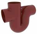
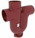
100 - PAM Building 05
d H L o p q r c s W g e d H L o p q r c s W g e p H L e s o f g d r W c p H L e o g d W c
BRANCH TRAPS DN < 200 DN L H W c d e f g o p q r s Access* Weight Product code 50 190 240 58 60 182 68 122 68 143 39 33 112 201 EP 50 2.5 156420 75 264 282 80 60 200 93 172 93 150 52 13 162 230 TS 50 4.6 176714 100 325 381 110 100 282 110 215 110 216 55 15 216 326 TS 50 7.9 156668 125 390 435 134 100 316 130 260 130 238 63 12 266 372 TS 75 10.7 156801 150 470 482 160 100 348 145 325 145 257 65 8 340 417 TS 125 16.9 156912 BRANCH TRAPS DN 200 DN L H W c d e f g o p r s Weight Product code 200 600 590 210 100 420 180 400 200 300 80 415 510 34.3 157018 “All dimensions are in mm and nominal weights are in kg”
Traps DN ≥ 250: Installation with 88° bends
Anti-syphon traps with bottom access door DN 50
Anti-syphon traps with bottom access door DN 100-150
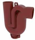
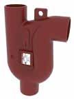
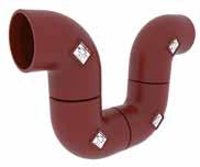
PAM Building - 101 05 PRODUCT CATALOG L H H L W c d H L W c d L H W c b L H W c b
DN L H 250 900 725 300 1070 860
DN L H W c d Weight Product code 50 165 255 58 80 187 2.5 229107
DN L H W b c Weight Product code 100 316 382 110 316 350 9.2 179013 150 412 531 160 412 470 24.8 156916 “All dimensions are in mm and nominal weights are in kg”
WASTEWATER
DOMESTIC USE - PAM-GLOBAL® S
TRAPS & VENTILATION I Traps
Anti-syphon traps with side access door*
Suitable for all wastewater drainage systems, the Anti-Syphon Trap is particularly well-suited to systems without secondary ventilation. It ensures the retention of a water seal within the body of the trap to prevent odors traveling backwards through the system and fouling the atmosphere around sinks, washbasins, baths, rainwater outlets, etc. The Anti-Syphon Trap works by preventing the siphoning effect of a heavy discharge through the system. It does this through the internal partition within the trap allowing the air to bypass the water, thus breaking the vacuum created by the discharge water.
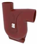
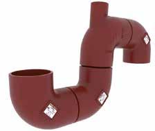
102 - PAM Building 05
b c L H a d e
Vertical outlet Dn
The vertical outlet version consists of 3 x product code: 155813 and 1 x product code : 156585
Vented traps DN Outlet L H a b c d e f Weight 100 Vertical 575 371 163 236 229 342 228 - 8.81 100 Horizontal 399 371 163 236 108 342 228 283 6.55
H p q L o c a W
*With brass closing
DN L H W a c o p q Weight Product code 50 165 230 58 136 80 130 213 155 2.8 156422 75 240 300 83 199 80 131 272 189 4.8 156522 “All dimensions are in mm and nominal weights are in kg”
TRAPS & VENTILATION I Roof penetrators
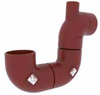
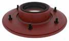

PAM Building - 103 05 PRODUCT CATALOG C C L H a b W C C L H a b W H a b c L e d
The horizontal outlet consists of 1 x product code: 156585 and 2 x product code: 155813 Horizontal outlet Dn DN Dn Product code 100 - 155813 100 50 156585 DN L H W a b Weight Product code 75 286 60 286 135 135 6.1 205922 100 324 60 324 158 246 6.6 205924 125 349 60 349 188 271 6.6 205925 DN Product code EPDM gasket Weight Product code NBR gasket Weight 75 179894 0.2 179895 0.2 100 207320 0.3 207319 0.3 125 207335 0.3 207334 0.3 “All dimensions are in mm and nominal weights are in kg”
WASTEWATER
DOMESTIC USE - PAM-GLOBAL® S
STACK SUPPORT
STACK SUPPORT PIPE
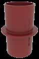
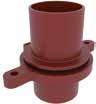
104 - PAM Building 05 H W L e g b f
H b L W
DN L H W b e f g ∅ Ext Weight Product code 50 195 220 108 8 150 17 30 108 2.5 156413 75 218 220 133 8 175 19 30 133 3.1 156512 100 259 220 162 8 214 20 32 162 4.3 156657 125 275 220 187 8 228 20 32 197 5.4 156793 150 300 220 222 8 255 22 32 222 7.2 156904 200 362 220 278 8 310 22 36 278 10.5 157014 250 444 300 354 8 394 25 40 354 19.1 157097 300 498 300 406 8 448 30 40 406 26.5 157160 400 600 340 508 10 550 30 50 508 43.9 248776 DN L H W b Weight Product code 50 87 220 87 8 1.3 156372 75 118 220 118 8 1.8 156462 100 145 220 145 8 2.4 156577 125 170 220 170 8 3.2 156745 “All dimensions are in mm and nominal weights are in kg”
STACK SUPPORT BRACKET
SPECIAL FITTINGS I Manifold connector
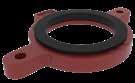
The multi-waste manifold simplifies waste plumbing by grouping all associated pipework from various sources such as sinks, basins, bidets, urinals and showers to one internal point above the finished floor level.
See p.174 for installation details.
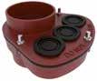
PAM Building - 105 05 PRODUCT CATALOG H e L h g W
W H L a e d W H L a e d
DN L H W e g h Weight Product code 50 195 17 108 150 30 108 1 179217 75 218 19 133 175 30 133 1.2 176713 100 259 20 162 214 32 162 1.6 179219 125 275 20 187 228 32 187 1.7 179220 DN L H W a d e Weight Product code 100 204 125 200 43 142 62 3.2 175626 150 265 165 290 70 184 81 6.1 175629 “All dimensions are in mm and nominal weights are in kg”
WASTEWATER
DOMESTIC USE - PAM-GLOBAL® S
SPECIAL FITTINGS I Single Stack Branch
Branches for single downpipe with 2 to 3 inlets - combined networks
SPECIAL FITTINGS I Compensators of movement
Conditions of use: Fittings intended to absorb the relative movement between two components of pipework; each one of its ends is fixed to 2 different structure elements.
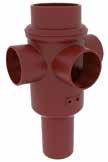
L is the dimension of the compensator in neutral position. The maximum authorised movements along the three axes are noted:
X axial movement
Y vertical radial movement
Z horizontal radial movement
Every reference is composed of:
• one movement absorber
• two bi-directional stack support pipes
Acceptable pressure for DN 75 to 200:
• negative pressures up to - 0.9 bar
• positive pressures up to 3 bar (accidental and internal hydrostatic pressure)
106 - PAM Building 05
p p o q p L H W Y 0 X Z
DN Lateral adjustments L H W o p q Weight Product code 100 3 consecutive DN 100 at 90° 280 490 230 392 140 282 11 177237 2 DN 100 at 90° 230 490 230 392 140 282 10.4 177236 2 DN 100 at 180° 280 490 180 392 140 282 10.8 177235 “All dimensions are in mm and nominal weights are in kg”
For short ranges of movements
For long ranges of movements
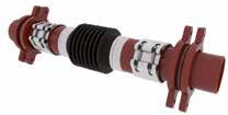
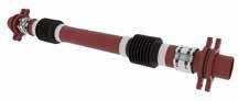
PAM Building - 107 05 PRODUCT CATALOG H L q r W O D L H q r W O D
DN OD L H W q r Socket extension Weight Product code X Y Z 75 83 895 218 83 81 139 ±30 ±30 ±30 18.4 on request 100 110 897 259 110 80 140 ±30 ±30 ±30 20.8 125 135 897 275 135 80 140 ±30 ±30 ±30 26 150 160 909 300 160 78 142 ±30 ±30 ±30 29.3 200 210 932 362 210 78 142 ±30 ±30 ±30 40.4 250 274 1143 444 274 115 185 ±30 ±30 ±30 83
DN OD L H W q r Socket extension Weight Product code X Y Z 75 83 1794 218 83 81 139 ±60 ±130 ±130 25.6 on request 100 110 1796 259 110 80 140 ±60 ±130 ±130 27.5 125 135 1796 275 135 80 140 ±60 ±130 ±130 33 150 160 1802 300 160 78 142 ±60 ±130 ±130 39.8 200 210 1824 362 210 78 142 ±60 ±130 ±130 55.6 “All dimensions are in mm and nominal weights are in kg”
WASTEWATER INTENSIVE USE - PAM-GLOBAL® Plus
PAM-GLOBAL® Plus - PIPES
* For dimensions over DN 400 please contact us.

PAM-GLOBAL® Plus - FITTINGS BENDS I Short radius bends

108 - PAM Building 05
L H W
a a L q H W a a L q H W
DN L H W Weight Product code 50 3000 58 58 12.9 155302 75 3000 83 83 18.8 176787 100 3000 110 110 25.1 155348 125 3000 135 135 35.3 155391 150 3000 160 160 42.1 155413 200 3000 210 210 69.1 155447 250 3000 274 274 99.5 155475 300 3000 326 326 129.4 155492 400 3000 429 429 179.5 155508 15° Bends DN L H W a q Weight Product code 50 66 80 58 40 66 0.4 155202 75 93 99 83 45 78 0.68 176781 100 121 112 110 50 83 1 155237 125 148 134 135 60 99 1.7 155262 150 173 148 160 65 108 2.5 155278 200 227 184 210 80 129 4.6 173774 400 455 284 429 100 181 21.4 on request “All dimensions are in mm and nominal weights are in kg”
BENDS I Short radius bends
* For dimensions over DN 400 please contact us.


PAM Building - 109 05 PRODUCT CATALOG a a L q H W a a L q H W
a a L q H W a a L q H W a a L q H W 22° Bends DN L H W a q Weight Product code 50 70 88 58 40 66 0.45 155308 75 97 105 83 47 74 0.8 155327 100 126 125 110 54 84 1.3 155358 125 152 143 135 61 92 1.9 155396 150 179 162 160 69 102 2.6 155421 200 233 200 210 83 122 4.4 155455 250 300 240 274 100 138 9.5 155482 30° Bends DN L H W a q Weight Product code 50 76 97 58 45 69 0.5 155203 75 102 114 83 50 73 0.8 176782 100 132 136 110 60 81 1.3 155238 125 160 164 135 70 96 2 155263 150 189 188 160 80 108 3 155279 200 243 229 210 95 124 5.4 179335
Bends DN L H W a q Weight Product code 50 84 106 58 50 65 0.6 155201 75 112 132 83 60 73 0.9 176735 100 142 158 110 70 80 1.6 155236 125 171 184 135 80 89 2.1 155261 150 199 210 160 90 97 3.2 155277 200 256 262 210 110 113 5.3 155289 250 324 319 274 130 125 10 155481 300 387 380 326 155 149 18.3 155498 400 540 573 429 247 270 34.4 155509 “All dimensions are in mm and nominal weights are in kg”
45°
WASTEWATER
INTENSIVE USE - PAM-GLOBAL® Plus
BENDS I Short radius bends
110 - PAM Building 05 a a L q H W
a a L q H W
68° Bends DN L H W a q Weight Product code 50 104 123 58 65 70 0.8 155200 75 131 149 83 80 72 1 176736 100 159 176 110 90 74 1.8 155235 125 188 205 135 105 80 3 155260 150 219 237 160 120 89 4.1 155276 200 277 295 210 145 99 7.8 155452 88° Bends DN L H W a q Weight Product code 50 104 107 58 75 49 0.8 155199 75 138 140 83 95 57 1.4 176737 100 166 169 110 110 59 2.2 155234 125 194 197 135 125 62 2.9 155259 150 227 230 160 145 70 4.3 155275 200 288 291 210 180 81 8.1 155451 250 360 363 274 223 89 13.5 155479 300 427 431 326 280 105 27.7 155496 400 644 651 429 466 223 59 on request “All dimensions are in mm and nominal weights are in kg”
BENDS I 88° Double bends
BRANCHES I Single branches
*For dimensions over DN 400 please contactus.
PAM Building - 111 05 PRODUCT CATALOG
L H o a a c b b W L H o a a c b b W
H b o c L p q r W
45° Branches DN dn L H W b c o p q r Weight Product code 50 50 144 185 58 135 135 50 165 124 36 1.35 155213 75 50 156 180 83 135 135 45 161 120 43 1.6 176740 75 179 215 83 155 155 60 198 140 40 2.2 176742 100 50 191 200 110 165 165 35 172 131 47 2.4 155245 75 214 235 110 170 170 50 209 151 46 3.2 176743 100 238 275 110 205 205 70 253 175 45 4 155255 125 50 218 205 135 185 185 20 170 130 44 3.2 155264 75 237 240 135 195 200 45 215 156 51 4.2 176784 100 261 280 135 220 220 60 254 177 47 5 155267 125 284 320 135 240 240 80 296 201 49 5.2 155271 150 75 265 255 160 210 220 35 220 161 54 5.1 176785 100 287 295 160 240 240 55 262 185 54 5.8 155281 125 307 325 160 255 255 70 298 202 52 7.4 155282 150 323 355 160 265 265 90 333 219 53 7.9 155285 200 100 340 310 210 265 265 40 275 198 67 9.3 155291 125 360 340 210 280 280 55 310 215 64 11.6 155292 150 383 375 210 300 300 75 353 240 66 12.3 155293 200 418 455 210 340 340 115 428 280 68 17.1 155295 250 150 440 405 274 350 350 55 358 245 75 22 208730 200 486 480 274 390 390 90 440 291 75 22.4 155483 250 537 580 274 430 430 130 530 335 70 29 155490 300 250 588 580 326 465 465 115 540 347 80 37.6 155500 300 634 660 326 505 505 155 661 431 115 46.3 155507 400 300 728 660 429 555 555 105 620 389 86 56.4 155510 400 820 835 429 645 645 190 795 492 101 98 on request DN L H W a b c o Weight Product code 50 148 148 58 121 50 100 148 1 235800 75 183 183 83 145 60 120 183 1.5 235801 100 228 228 110 170 70 140 228 2.8 155359 “All dimensions are in mm and nominal weights are in kg”
WASTEWATER
INTENSIVE USE - PAM-GLOBAL® Plus
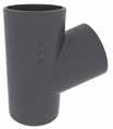
BRANCHES I
Single branches
112 - PAM Building 05
H b o c L p q r W H b o c L p q r W
68° Branches DN dn L H W b c o p q r Weight Product code 50 50 118 145 58 80 80 55 117 65 37 1 155315 75 75 158 180 83 110 110 70 149 72 37 2 155343 100 100 195 220 110 130 130 85 189 87 50 2.8 155379 125 125 235 255 135 155 155 100 220 95 50 4.5 155408 150 150 276 295 160 180 180 115 256 108 55 6.5 155441 200 200 352 365 210 225 225 140 321 126 63 12 155469 88° Branches DN dn L H W b c o p q r Weight Product code 50 50 110 145 58 66 80 79 111 53 31 1 155212 75 50 132 160 83 75 90 85 117 59 42 1.5 176744 75 138 180 83 85 95 95 140 57 37 1.6 176745 100 50 161 170 110 76 105 94 127 69 45 2 155244 75 166 190 110 90 110 100 145 62 40 2.4 155746 100 172 220 110 105 115 115 174 64 41 2.8 155253 125 100 199 235 135 110 130 125 184 74 48 4.2 173022 125 205 260 135 123 135 137 209 74 48 5 155407 150 100 227 245 160 115 145 130 190 80 52 5.6 155428 150 237 300 160 142 155 158 243 83 55 6.7 155440 200 200 388 365 210 172 183 193 296 86 67 11 155468 250 250 366 455 274 228 243 240 375 101 77 19.5 155488 300 300 434 530 326 265 265 265 437 111 87 35 155505 400 400 616 684 429 314 370 370 595 165 90 67 on request “All dimensions are in mm and nominal weights are in kg” H b o c L p q r W
BRANCHES I Long tail single branches
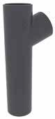
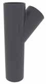
PAM Building - 113 05 PRODUCT CATALOG H b c d e L p q r W H b c d e L p q r W H b d c e r q p L W H b d c e r q p L W
45° Branches DN dn L H W b c d e p q r Weight Product code 100 100 238 430 110 205 205 225 170 424 346 241 5.3 155381 68° Branches DN dn L H W b c d e p q r Weight Product code 100 100 195 460 110 130 130 330 250 430 328 290 4.8 155388 “All dimensions are in mm and nominal weights are in kg” - “Hatch patterned area in the drawings shows the max. cutting length”.
WASTEWATER
INTENSIVE USE - PAM-GLOBAL® Plus
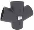
BRANCHES I Double branches
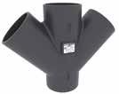
114 - PAM Building 05 H b c L p q r d W H b c L p q r d W
double branches H b c d L p q r W
Short
45° Branches DN dn L H W b c d p q r Weight Product code 100 100 346 260 110 190 190 70 243 165 46 5.3 155384 125 125 421 305 135 240 240 65 285 190 45 7.9 155411 150 150 488 355 160 265 265 90 334 277 55 11.8 155445 68° Branches DN dn L H W b c d p q r Weight Product code 50 50 178 145 58 85 85 60 118 64 35 1.2 155317 75 75 234 180 83 110 110 70 149 72 36 2.3 155345 100 100 281 220 110 130 130 85 189 87 50 3.4 155383 125 125 336 255 135 155 155 100 220 95 51 5.5 155410 150 150 392 295 160 180 180 115 256 108 57 8.2 155444 “All dimensions are in mm and nominal weights are in kg” H b c d L p q r W
BRANCHES I Double branches
Corner branches - Short corner branches
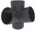
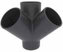
PAM Building - 115 05 PRODUCT CATALOG
H c b d L p q r W H c b d L p q r W H b d c L p q r W H b d c L p q r W 45° Branches DN dn L H W b c d p q r Weight Product code 100 100 227 260 227 190 190 70 242 166 46 5.2 155387 68° Branches DN dn L H W b c d p q r Weight Product code 75 75 158 180 158 110 110 70 149 72 36 2.1 155346 100 100 195 220 195 130 130 90 189 87 50 3.5 155386 “All dimensions are in mm and nominal weights are in kg”
WASTEWATER
INTENSIVE USE - PAM-GLOBAL® Plus
BRANCHES I
Single long arm branches
TAPERED PIPES I Reducers
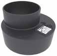
*For dimensions over DN 400 please contact us.
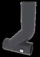
116 - PAM Building 05 H a c p L W
H b L W c d
DN dn L H W a c p Weight Product code 100 100 282 450 110 260 70 340 61 155389 DN dn L H W b c d Weight Product code 75 50 83 80 83 47 30 13 0.65 176747 100 50 110 80 110 45 30 26 0.9 155209 75 110 90 110 45 35 14 1 176748 125 50 135 85 135 50 30 39 1.5 155210 75 135 95 135 52 35 26 1.3 176749 100 135 95 135 50 40 13 1.6 155250 150 50 160 95 160 55 30 51 1.9 155211 75 160 100 160 57 35 39 1.9 176750 100 160 105 160 60 40 25 2 155251 125 160 110 160 60 45 13 2 155269 200 100 210 115 210 70 40 50 3.6 155252 125 210 120 210 70 45 38 3.8 155270 150 210 125 210 65 50 25 3.4 155284 250 100 274 125 274 82 43 82 6 155377 150 274 135 274 82 50 57 6.3 155437 200 274 145 274 80 60 32 6.9 155465 300 150 326 150 326 97 50 83 11 155438 200 326 160 326 95 60 58 10.2 155466 250 326 170 326 95 70 26 10.7 155487 400 300 429 200 429 100 100 52 19.6 155504 “All dimensions are in mm and nominal weights are in kg”
ACCESS FITTINGS I Access pipes
ACCESS FITTINGS I Access pipes
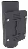
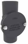
PAM Building - 117 05 PRODUCT CATALOG
H c L W b d d e L H c f W d e L H c f W
Round door DN L H W b c d Weight Product code 50 105 190 93 64 53 105 2.3 179348 75 134 220 115 73 78 134 3.2 179648 100 159 260 139 84 104 159 5 179350
door DN L H W c d e f Weight Product code 125 190 370 169 255 225 125 101 10.3 179352 150 215 395 192 280 250 150 112 14.5 179353 200 262 435 242 330 330 200 137 22 179354 “All dimensions are in mm and nominal weights are in kg”
Rectangular
WASTEWATER INTENSIVE USE - PAM-GLOBAL® Plus
ACCESS FITTINGS I Blank ends
ACCESS FITTINGS I Expansion plugs
W
See p.151 for information on resistance to accidental pressure. Expansion plugs with bleeding valve are available on request for DN 125/DN 150 and DN 200 (for watertightness test).
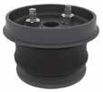
118 - PAM Building 05 H L W
H o L
DN L H W Weight Product code 50 58 30 58 0.25 155197 75 83 35 83 0.45 176783 100 110 40 110 0.8 155231 125 135 45 135 1.2 155257 150 160 50 160 1.7 155273 200 210 60 210 3.2 155287 250 274 70 274 5.9 155477 300 326 80 326 10 155494 DN L H W o Weight Screw Product code 50 62 47 62 14 0.22 M8x30 155303 75 90 71 90 20 0.6 M8x50 155322 100 118 77 118 23 1.2 M8x60 155351 125 143 77 143 24 1.7 M8x60 155392 150 168 73 168 22 2.4 M10x45 155417 200 220 87 220 26 5 M10x60 155450 “All dimensions are in mm and nominal weights are in kg”
TRAPS I Branch traps
(*) with bottom cleaning access: EP by expansion plug / TS by tight sheet
Designed for rainwater networks. The arrows stamped on the cast iron body show the fl ow direction.
STACK SUPPORT
Designed for rainwater networks when subjected to aggressive environments.

PAM Building - 119 05 PRODUCT CATALOG
p H L e s o f g d r W c p H L e s o g d r W c H W L e g b f
d H L o p q r c s W g e d H L o p q r c s W g e
BRANCH TRAP DN < 200 DN L H W c d e f g o p q r s Access* Weight Product code 50 190 240 58 60 182 68 122 68 143 39 33 112 201 EP 50 2.5 155311 75 264 282 80 60 200 93 172 93 150 52 13 162 230 TS 50 4.6 176739 100 325 381 110 100 282 110 215 110 216 55 15 216 326 TS 50 7.9 155372 125 390 435 134 100 316 130 260 130 238 63 12 266 372 TS 75 10.7 155404 150 470 482 160 100 348 145 325 145 257 65 8 340 417 TS 125 16.9 155436 DN L H W b e f g ∅ Ext Weight Product code 50 195 220 108 8 150 17 30 108 2.5 212273 75 218 220 133 8 175 19 30 133 3.1 211041 100 259 220 162 8 214 20 32 162 4.3 171912 125 275 220 187 8 228 20 32 197 5.4 211042 150 300 220 222 8 255 22 32 222 7.2 171914 300 498 300 406 8 448 30 40 406 26.5 208264 400 600 340 508 10 550 30 50 508 43.9 on request BRANCH TRAP DN 200 DN L H W c d e f g o p r s Weight Product code 200 600 590 210 100 420 180 400 200 300 80 415 510 34.3 155464 “All dimensions are in mm and nominal weights are in kg”
WASTEWATER
INTENSIVE USE - SMU Zn
SMU Zn - PIPES
* For dimensions over DN 300 please contact us.
SMU Zn - FITTINGS
For details of the fittings to be used with SMU Zn pipes, please contact us.
“All dimensions are in mm and nominal weights are in kg”
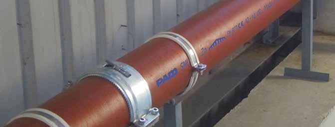
120 - PAM Building 05
L H W
DN L H W Weight Product code 50 3000 58 58 12.9 241706 75/80 3000 83 83 18.8 241708 100 3000 110 110 25.1 241709 125 3000 135 135 35.3 253994 150 3000 160 160 42.1 241710 200 3000 210 210 69.1 253915 250 3000 274 274 99.5 253916 300 3000 326 326 129.4 253917
RECENT PROJECTS IN ASIA WITH SMU ZN


PAM Building - 121 05 PRODUCT CATALOG
1 - The Millennity - Hong Kong
2 - NOVO LAND - Honk Kong
3 - Wong Chuk Hang (AIL 351)
4 - Shangri-La Island Hotel - Hong Kong
5 - Shaw Auditorium HKUST - Hong Kong
6 - Studio City Phase 2 - Macau
7 - 11 SKIES Commercial Complex - Hong Kong
8 - HKIA Terminal 2 extensions - Hong Kong
9 - Kai Tak Sports Ground - Hong Kong
1 2 3 4 5 6 7 8 9
RAINWATER
GRAVITY SYSTEMS - Residential (Type R)
All our Residential (Type R) downpipes and fittings are delivered with their couplings (see p.124 )
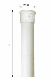
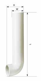
GRAVITY SYSTEMS - PIPES
ROUND DOWNPIPES I Straight
ROUND DOWNPIPES I Bended
122 - PAM Building 05 H W L
H W L L
DN L H W Weight Product code 75 1 m 107 107 6.9 155536 2 m 107 107 12.9 155539 100 1 m 134 134 9.2 155595 2 m 134 134 17.2 155599 125 1 m 162 162 12.9 155662 2 m 162 162 24.2 155666 DN L H W Weight Product code 75 1 m 154 107 7.6 155572 2 m 154 107 13.6 155574 100 1 m 177 134 10.1 155640 2 m 177 134 18.1 155643 125 1 m 206 162 14.2 155700 2 m 206 162 25.5 155702 “All dimensions are in mm and nominal weights are in kg”
GRAVITY SYSTEMS - FITTINGS
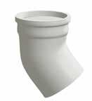
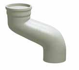
BENDS I Round downpipe bends
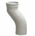
*Availability: Contact us
OFFSETS I Round offsets
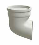
PAM Building - 123 05 PRODUCT CATALOG “All dimensions are in mm and nominal weights are in kg” H W L
Bend with socket DN L H W Weight Product code 75 162 210 116 2.2 155557 100 186 226 145 3.2 155622 125 215 250 173 4.6 155684 68° Bend with socket DN L H W Weight Product code 75 148 122 115 2 155555* 100 210 185 144 3.5 155619 125 242 198 173 5.1 155681 W E H L
45°
with socket / E =
DN L H W Weight Product code 100 202 311 144 4.3 155630 W E H L Offset with socket / E =
DN L H W Weight Product code 100 277 317 144 4.1 155626 W L H
Offset
75
150
GRAVITY SYSTEMS - Residential (Type R)
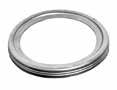
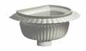

124 - PAM Building 05
RAINWATER
DECORATIVE RAINWATER HEAD W H L ACCESSORIES I Couplings DN L H W Weight Product code 75 385 260 260 12.5 156510 100 385 260 274 13.8 156656 125 385 260 289 14.1 156792 Couplings for downpipes and shoes DN Weight Product code 75 0.03 155566 100 0.04 155632 125 0.05 155694 Couplings for bends and offsets DN Weight Product code 75 0.07 261497 100 0.09 261498 125 0.11 261499 “All dimensions are in mm and nominal weights are in kg”
GARGOYLE I For roadsides (Profile A)
GARGOYLE I For pavements (Profile T)
GARGOYLE I Shoe to head connector
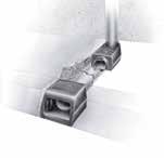
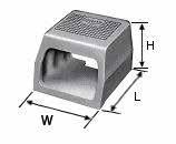
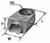
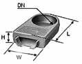
PAM Building - 125 05 PRODUCT CATALOG “All dimensions are in mm and nominal weights are in kg”
DN Entitled L H W Weight Product code 75 Shoe 196 57 140 3.1 157373 100 Shoe 196 57 140 2.8 157377 100 Head 150 65 162 2.5 157379 DN Entitled L H W Weight Product code 75 Shoe 191 110 140 3.9 157374 100 Shoe 191 110 140 3.6 157378 100 Head 162 130 162 4.4 157382 DN Entitled Weight Product code DN 75 PAM-GLOBAL Plus pipe 18.8 176787 DN 100 PAM-GLOBAL Plus pipe 25.1 155348 120 X 40 Rectangular pipe 21 157385
RAINWATER
SIPHONIC SYSTEMS - EPAMS®
EPAMS® - OUTLETS OUTLETS TO BE WELDED
• Stainless steel body, including M10 bolts
• Aluminum grating
*This outlet is the basis for the next three outlets, on which various elements are grafted depending on the application field. See p.179 for main dimensions.
OUTLETS WITH FLANGE
• Stainless steel body, including M10 bolts
• Aluminum grating
• Aluminum flange
OUTLETS WITH STEEL PLATE
• Stainless steel body, including M10 bolts
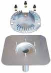
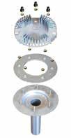
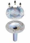
• Aluminum grating
• Stainless steel plate - 500 x 500 mm
126 - PAM Building 05
DN DE (mm) Capacity l/s Surface drainage (m2) Weight (kg) Product code 50 58 13 260 5.4 171288 75 83 23 460 5.7 171289 100 110 26 520 6.4 171290 125* 135 26* 520 8.3 172871 DN DE (mm) Capacity l/s Surface drainage (m2) Weight (kg) Product code 50 58 13 260 6.2 171283 75 83 23 460 6.5 171284 100 110 26 520 7.2 171285 125* 135 26* 520 9.1 172850 DN DE (mm) Capacity l/s Surface drainage (m2) Weight (kg) Product code 50 58 13 260 6.4 171081 75 83 23 460 6.7 171267 100 110 26 520 7.4 171305 125* 135 26* 520 9.3 172874
* The advantage of the DN 125 outlet is in the “gutters” application where the water cover height can exceed 55 mm (see French Technical Approval 5.2/ 14-2386_V2)
OUTLETS FOR FLEXIBLE PVC MEMBRANES
• Stainless steel body, including M10 bolts
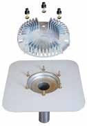
• Aluminum grating
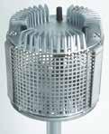
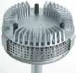
• Laminate-steel PVC plate - 500 x 500 mm
EPAMS - ACCESSORIES ELEVATING KITS
• Anti-vortex device fitted to Elevating Kit
• For roofs with waterproofing protection by fine gravel or by flags on isolating layer by fine gravel
ANCHORING STEEL PLATE
NUTS & SCREWS
PAM Building - 127 05 PRODUCT CATALOG
90 mm 250 mm
DN DE (mm) Capacity l/s Surface drainage (m2) Weight (kg) Product code 50 58 13 260 6.8 171286 75 83 23 460 7.1 171287 100 110 26 520 7.7 171263 125* 135 26* 520 9.6 172876 Description Height (mm) Product code Elevating device + anti-vortex 90 171291 Elevating device + anti-vortex 250 171292 Description Product code Anchoring steel plate 172431 Description Weight (kg) Product code Valid for all DN 0.01 171295 * The
DN 125
“gutters”
cover height can exceed 55 mm (see French Technical Approval 5.2/ 14-2386_V2)
advantage of the
outlet is in the
application where the water
ITINERO® - PIPES
ITINERO® - FITTINGS
BENDS I Short radius bends
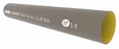
128 - PAM Building 05
L H W a a L q H W
DN L H W Weight Product code 100 3000 110 110 25.1 277898 125 3000 135 135 35.3 277845 150 3000 160 160 42.1 277862 200 3000 210 210 69.1 277863 250 3000 274 274 99.5 277864 300 3000 326 326 129.4 277865 400 3000 429 429 179.5 277866 500 3000 532 532 247.6 277846 600 3000 635 635 325.5 277847 45° Bends DN L H W a q Weight Product code 100 142 158 110 70 80 1.6 277899 125 171 184 135 80 89 2.1 277827 150 199 210 160 90 97 3.2 277867 200 256 262 210 110 113 5.3 277868 250 324 319 274 130 125 10 277869 300 387 380 326 155 149 18.3 277870 400 540 573 429 247 270 34.4 277871 500 730 678 532 318 350 52 277861 600 788 821 635 350 370 111 277852 “All dimensions are in mm and nominal weights are in kg”
INFRASTRUCTURE ITINERO®
BRANCHES I Single branches

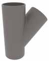
PAM Building - 129 05 PRODUCT CATALOG H b o c L p q r W
a a L q H W 88° Bends DN L H W a q Weight Product code 100 166 169 110 110 59 2.2 277905 125 194 197 135 125 62 2.9 277826 150 227 230 160 145 70 4.3 277879 200 288 291 210 180 81 8.1 277880 250 360 363 274 223 89 13.5 277881 300 427 431 326 280 105 27.7 277882 400 644 651 429 466 223 59 277896 45° Branches DN dn L H W b c o p q r Weight Product code 100 100 238 275 110 205 205 70 253 175 45 4 277824 125 100 261 280 135 220 220 60 254 177 47 5 277830 125 284 320 135 240 240 80 296 201 49 5.2 277832 150 100 287 295 160 240 240 55 262 185 54 5.8 277835 125 307 325 160 255 255 70 298 202 52 7.4 277836 150 323 355 160 265 265 90 333 219 53 7.9 277837 200 100 340 310 210 265 265 40 275 198 67 9.3 277838 125 360 340 210 280 280 55 310 215 64 11.6 277839 150 383 375 210 300 300 75 353 240 66 12.3 277883 200 418 455 210 340 340 115 428 280 68 17.1 277884 250 100 398 330 274 315 315 15 276 198 72 13.6 277914 125 420 370 274 335 335 35 318 223 75 17.8 277911 150 440 405 274 350 350 55 358 245 75 22 277885 200 486 480 274 390 390 90 440 291 75 22.4 277886 250 537 580 274 430 430 130 530 335 70 29 277887 300 100 445 350 326 345 345 5 287 208 88 18.9 277915 125 464 360 326 360 360 15 316 221 80 22.7 277909 150 487 415 326 380 380 35 359 246 81 28 277913 200 547 485 326 415 440 70 454 305 81 31 277908 250 588 580 326 465 465 115 540 347 80 37.6 277888 300 634 660 326 505 505 155 661 431 115 46.3 277889 400 300 728 660 429 555 555 105 620 389 86 56.4 277890 500 300 861 720 532 635 680 85 680 448 114 86 277907 600 300 965 725 635 687 751 38 683 452 115 100 277850 “All dimensions are in mm and nominal weights are in kg”
TAPERED PIPES I Reducers
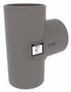
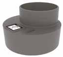
130 - PAM Building 05
H b L W c d INFRASTRUCTURE ITINERO® DN dn L H W b c d Weight Product code 125 100 135 95 135 50 40 13 1.6 277822 150 100 160 105 160 60 40 25 2 277900 125 160 110 160 60 45 13 2 277872 200 100 210 115 210 70 40 50 3.6 277823 125 210 120 210 70 45 38 3.8 277831 150 210 125 210 65 50 25 3.4 277873 250 150 274 135 274 82 50 57 6.3 277874 200 274 145 274 80 60 32 6.9 277875 300 150 326 150 326 97 50 83 11 277876 200 326 160 326 95 60 58 10.2 277877 250 326 170 326 95 70 26 10.7 277840 400 300 429 200 429 100 100 52 19.6 277878 500 400 532 200 532 100 100 52 28.9 277860 “All dimensions are in mm and nominal weights are in kg” H b o c L p q r W H b o c L p q r W
DN dn L H W b c o p q r Weight Product code 300 300 434 530 326 265 265 265 437 111 87 35 278355 400 300 590 650 429 297 370 353 529 203 121 58 278356
88° Branches
ACCESS FITTINGS I

ACCESS FITTINGS I Blank ends
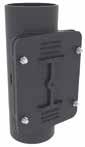
STACK SUPPORT
PAM Building - 131 05 PRODUCT CATALOG
H L W H L W
H W L e g b f H W L e g b f d e L H c f W d e L H c f W
Access pipes Rectangular door DN L H W c d e f Weight Product code 100 160 340 138 230 200 100 83 7.6 277857 125 190 370 169 255 225 125 101 10.3 277858 150 215 395 192 280 250 150 112 14.5 277859 200 262 435 242 330 300 200 137 22 277916 250 330 540 307 380 350 260 170 38.5 277917 300 380 610 358 430 400 310 195 50 277918 DN L H W Weight Product code 100 110 40 110 0.8 277819 125 135 45 135 1.2 277825 150 160 50 160 1.7 277901 200 210 60 210 3.2 277902 250 274 70 274 5.9 277903 300 326 80 326 10 277904 400 429 98 429 21 277895 DN L H W b e f g ∅ Ext Weight Product code 100 259 220 162 8 214 20 32 162 4.3 277906 150 300 220 222 8 255 22 32 222 7.2 277891 200 362 220 278 8 310 22 36 278 10.5 277892 250 444 300 354 8 394 25 40 354 19.1 277893 300 498 300 406 8 448 30 40 406 26.5 277894 400 600 340 508 10 550 30 50 508 43.9 277897 “All dimensions are in mm and nominal weights are in kg”
COUPLINGS, COLLARS & CONNECTORS
STANDARD COUPLINGS
Standard version W2 technical specifications: Strap, clamps:
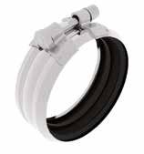
1.4510 /11 (AISI 430Ti / 439)
All stainless steel version W5 technical specifications:
Strap, clamps:
1.4404 / 1.4571 (AISI 316 L/316Ti)
Screw and nut: austenitic stainless steel A4-70 or AISI 316
The PAM Rapid is designed for full tightening with “zero gap”, there is no need to check the torque. For DN 250 and 300, apply the following torque: 25 N.m.
For wastewater liable to contain hot oil, solvents or hydrocarbons, it is recommended to use couplings equipped with specific NBR gaskets.
132 - PAM Building 05
W H L
PAM RAPID-S / PAM RAPID INOX DN L H W Weight PAM RAPID-S PAM RAPID INOX W2 W5 50 70 80 42 0.1 210424 185635 75 90 103 42 0.12 210426 207819 100 125 139 48 0.18 210427 185636 125 147 161 56 0.28 210428 207820 150 172 187 56 0.32 210429 207831 200 223 240 70 0.6 210430 185637 250 290 315 95 1.1 228759 228773 300 350 375 95 1.25 228771 228775
DN L H W Weight PAM RAPID NBR GASKET W5 50 70 80 42 0.1 212705 75 90 103 42 0.12 212708 100 125 139 48 0.18 212709 125 147 161 56 0.28 212710 150 172 187 56 0.32 212711 200 223 240 70 0.6 212712 250 290 315 95 1.1 212713 300 350 375 95 1.25 212714 “All dimensions are in mm and nominal weights are in kg”
PAM RAPID INOX WITH NBR GASKET (Nitrile coupling)
All stainless steel
Strap: austenitic stainless steel1.4404/1.4571
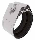
(AISI 316L/316Ti)
Barrels: austenitic stainless steel
-1.4404/1.4571 (AISI 316/316L/316Ti)
Screw: stainless steel A4-70, with anti-seizing coating.
(thrust collar: AISI 316/316L)
Sealing gasket: EPDM
PAM R ("R" FOR REPAIR)
PAM Building - 133 05 PRODUCT CATALOG
DN L H W Weight Product code 50 67 86 50 0.18 233899 75 91 110 50 0.2 233900 100 118 137 58 0.29 233901 125 147 166 58 0.31 233902 150 167 186 58 0.36 233903 200 223 242 58 0.47 233904 “All dimensions are in mm and nominal weights are in kg”
COUPLINGS, COLLARS & CONNECTORS
HIGH PRESSURE COUPLINGS
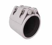
Type W4
Casing: 1.4301 / AISI 304
Screws: 1.4404 / AISI 316L
Barrels: 1.4401/ AISI 316
Strengthening plate: 1.4301 / AISI 304
Sealing gasket: EPDM or NBR
Type W5
Casing: 1.4404 / AISI 316L
Screws: 1.4404 / AISI 316L
Barrels: 1.4401/ AISI 316
Strengthening plate: 1.4404 / AISI 316L
Sealing gasket: EPDM or
134 - PAM Building 05
L W H e C
NBR
PAM HP FLEX-S (W4) DN L H W c e Pressure Resistance bar Torque Nm Screw Weight Product code EPDM NBR 100 89 150 133 42 5 10 25 M8 1.6 278442 278451 125 114 177 155 67 5 10 25 M10 2.3 278443 278452 150 114 202 181 67 5 10 25 M10 2.5 278444 278453 200 114 252 242 67 5 10 25 M10 3.2 278445 278454 250 114 316 295 67 5 10 25 M10 3.5 278446 278455 300 144 414 352 81 5 10 40 M10 9.5 278447 278456 400 144 516 458 81 5 10 80 M10 9 278448 278457 500 144 619 561 81 5 6 80 M10 11 278449 278458 600 144 721 663 81 5 6 80 M10 13 278450 278459 PAM HP FLEX-INOX (W5) DN L H W c e Pressure Resistance bar Torque Nm Screw Weight Product code EPDM NBR 100 89 150 133 42 5 10 25 M8 1.6 278478 278487 125 114 177 155 67 5 10 25 M10 2.3 278479 278488 150 114 202 181 67 5 10 25 M10 2.5 278480 278489 200 114 252 242 67 5 10 25 M10 3.2 278481 278490 250 114 316 295 67 5 10 25 M10 3.5 278482 278491 300 144 414 352 81 5 10 40 M10 9.5 278483 278492 400 144 516 458 81 5 10 80 M10 9 278484 278493 500 144 619 561 81 5 6 80 M10 11 278485 278494 600 144 721 663 81 5 6 80 M10 13 278486 278495 “All dimensions are in mm and nominal weights are in kg”
GRIPPED HIGH PRESSURE COUPLINGS
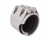
PAM Building - 135 B B 05 PRODUCT CATALOG Type W4 Casing: 1.4301 / AISI 304 Screws: 1.4404 / AISI 316L Barrels: 1.4401/ AISI 316
plate: 1.4301 / AISI 304 Sealing gasket: EPDM or NBR Grips: 1.4310 / AISI 301 Type W5 Casing: 1.4404 / AISI 316L Screws: 1.4404 / AISI 316L Barrels: 1.4401/ AISI 316 Strengthening plate: 1.4404 / AISI 316L Sealing gasket: EPDM or NBR Grips: 1.4310 / AISI 301 e C H L W
Strengthening
PAM HP GRIP-S (W4) DN L H W c e Pressure Resistance bar Torque Nm Screw Weight Product code EPDM NBR 100 89 156 139 16 8 10 25 M10 1.4 278460 278469 125 114 192 166 24 8 10 60 M12 2.6 278461 278470 150 114 218 191 24 8 10 85 M16 3.2 278462 278471 200 114 269 241 24 8 10 60 M16 5.0 278463 278472 250 114 357 304 24 8 10 80 M16 8.6 278464 278473 300 114 410 357 24 8 10 80 M16 10.0 278465 278474 PAM HP GRIP-INOX (W5) DN L H W c e Pressure Resistance bar Torque Nm Screw Weight Product code EPDM NBR 100 89 156 139 16 8 10 25 M10 1.4 278496 278505 125 114 192 166 24 8 10 60 M12 2.6 278497 278506 150 114 218 191 24 8 10 85 M16 3.2 278498 278507 200 114 269 241 24 8 10 60 M16 5.0 278499 278508 250 114 357 304 24 8 10 80 M16 8.6 278500 278509 300 114 410 357 24 8 10 80 M16 10.0 278501 278510 400 142 499 473 63 10 10 160 M16 10.3 269446500 146 603 575 63 10 6 160 M16 16.9 269447600 146 711 683 63 10 6 160 M16 19.6 269448“All dimensions are in mm and nominal weights are in kg”
COUPLINGS, COLLARS & CONNECTORS
CONNECTORS
Stepping rings
GRIP COLLARS
Totally versatile, the PAM grip collar is compatible with all the PAM designed couplings or those of equivalent shape.
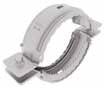
“All dimensions are in mm and nominal weights are in kg”
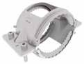
136 - PAM Building 05 Pressure resistance DN 50-125: 10 bar DN 150-200: 5 bar DN 250-300: 3 bar H a b c L W Pressure resistance DN 50-125: 10 bar DN 150-200: 5 bar L H W c b a
GRIP COLLARS FOR COUPLINGS DN L H W a b c Wrench dimension Weight Product code 50 132 76 88 88 22 72 6 0.45 221261 75 155 78 105 105 25 73 6 0.53 221268 100 211 93 145 145 33 88 6 0.9 220750 125 229 93 165 165 32 88 6 1 221269 150 260 102 196 196 32 96 6 1.2 221270 200 316 118 252 252 32 115 8 1.7 221271 250 394 140 318 318 38 131 8 2.3 227039 300 447 140 371 371 38 131 8 2.5 227040
COLLARS
PLUGS DN L H W a b c Wrench dimension Weight Product code 50 132 47 88 88 22 43 6 0.33 222092 75 155 47 105 105 25 41 6 0.4 222127 100 211 50 145 145 33 45 6 0.6 221563 125 229 54 165 165 32 49 6 0.7 222129 150 260 56 196 196 32 51 6 0.9 222131 200 316 64 252 252 32 60 8 1.2 222133
GRIP
FOR EXPANSION
Saint-Gobain PAM Soil & Drain Tel: +33 PAM Building • Tel: +33 (0) 383 Datasheet - Connectors - Stepping
DESCRIPTION Part of the PAM Building cast Stepping Rings (SR) are
stepping
the drainage
waste
Water tightness
EPDM
RECOMMENDED USE • Wastewater • Valve water • Rainwater STANDARDS & APPROVALS • Industry Product Standards: • NF EN877 • NF EN681-1
used to connect of different outside diameters
ring is suitable for the
of
water, valve
is ensured with with an
gasket or an depending on the material type and
CONNECTORS
Stepping rings
CONNECTORS
For connection to other materials refer to the table on p.171.
cast iron connector offer, connect pipe and fittings or material type. The S and PLUS ranges for valve water and rainwater. a PAM Rapid coupling Adapting Collars (AC) and circumference.
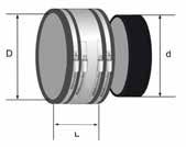
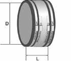
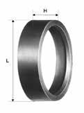
MATERIAL
• 100% elastomer EPDM
APPROVALS
ENVIRONMENTAL DATA
* External diameters of other materials
• Recycling Information: Partially recyclable
* minimum / maximum external diameter of the pipes to be connected
tcbatiment.sgpam@saint-gobain.com • www.pambuilding.com
tcbatiment.sgpam@saint-gobain.com www.pam-drainage-solutions.com
* minimum / maximum external diameter of the pipes to be connected
PAM Building - 137 05 PRODUCT CATALOG
+33 (0) 383 807 808 383 807 808 •
Product Data SheetPAM BuidingOctober 13 2022
Email:
Email:
STEPPING RINGS DN L H DE* Weight Other Materials Product code 50 57 20 50 0.02 HDPE and PVC 156399 75 83 22 63 0.06 HDPE 156495 25 77 0.03 PVC 156494 100 110 25 91 0.1 PVC 156535 100 0.05 HDPE 156555 125 135 25 125 0.06 HDPE and PVC 156778 200 208 35 200 0.15 HDPE and PVC 157000 250 272 35 250 0.45 HDPE and PVC 157085 ADAPTING COLLARS DN D min.* D max.* L Weight Product code 75 75 90 100 0.4 255300 100 100 115 100 0.7 155002 100 110 121 120 0.7 TXB10NP01 125 130 150 120 1 TXB12NL0G 150 150 175 120 1 TXB15NM0J 200 200 225 150 1.5 TXB20NL0K 300 310 335 190 2.9 TXB30NN02
COLLAR AND STEPPING RING DN D min.* D max.* d min.* d max.* L Weight Product code 200 200 225 192 201 150 1.9 TXB20NN0K “All dimensions are in mm and nominal weights are in kg”
ADAPTING
COUPLINGS, COLLARS & CONNECTORS
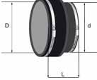

* minimum / maximum external diameter of the pipes to be connected
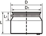
Transitional connectors
DN 50-125 are designed for connecting the cast iron S and Plus ranges to other materials, whether steel or plastic. The connections with these flexible connectors are easy and safe: one pre-cut lid and a lip seal inside (see figure). EPDM and hose clamp made of chrome steel no. 1.4016.
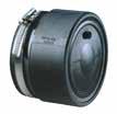

138 - PAM Building 05 DN 50 156394 DN 100 156628 DN 75 156492 DN 100 156629
ADAPTING JOINTS DN D min.* D max.* d min.* d max.* L Weight Product code 150 155 170 130 145 120 0.8 155003 200 170 193 210 235 150 1.5 155004 EPDM PLUGS DN 1st aperture ∅ in mm 2nd aperture ∅ in mm 3rd aperture ∅ in mm Weight Product code with stainless steel collar 50 32 or 40 or 42 - - 0.1 156394 75 (32 or 40) or (42 or 50) - - 0.2 156492 100 32 or 40 or 42 32 - 0.3 156628 without stainless steel collar 100 (32 or 40) or 42 (32 or 40) or (42 or 50) (32 or 40) or (42 or 50) or 54 0.4 156629 PAM Konfix DN D1 D Ext. Ø Connecting pipe mm L1 L Insert depth mm Weight Product code 50 50 72 40-56 20 58 35 0.1 155759 75 82 92 56-75 22 72 45 0.16 180852 100 100 126 102-110 28 90 57 0.3 155833 125 125 151 125 36 106 65 0.7 155883 “All dimensions are in mm and nominal weights are in kg”
For connecting up to three 32-56 mm pipes made out of other materials to a cast iron pipe system DN 100. EPDM and hose clamp made of chrome steel no. 1.4016.
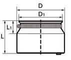
The Multiquick connector DN 100x70 allows connections between other materials with an outside diameter from 72 to 110 mm, to our cast iron range DN 100 with a maximum outside diameter of 115 mm. There are several pre-cut options. EPDM and hose clamp made of chrome steel no. 1.4016.
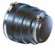
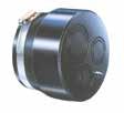
PAM Building - 139 05 PRODUCT CATALOG
PAM
DN D1 D Ext. Ø Connecting pipe mm L1 L Insert depth mm Weight Product code 100 108 134 32-56 36 91 40 0.3 176811 PAM Multiquick DN Ø D1 Ø D2 Ø D3 Ø D4 Ø d1 Ø d2 Ø d3 Ød4 H Weight Product code 100x70 117 111 101 81 108 104 94 74 107 0.15 176812 “All dimensions are in mm and nominal weights are in kg”
Konfix-Multi
SUPPORTING & FIXING SYSTEMS
BRACKETS
Quick hooking thanks to the opening
In galvanised steel. Distance between pipe and wall: 1 cm.
Fixing settings
Ease of fixation thanks to a 4 cm opening in the upper part of the hook
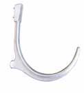
Reduced bearing surface Recesses to address wall roughness
Automatic set up Level marking on the hook that represents the waterline AS13 aluminium / not corrodible


140 - PAM Building 05
a
COLLARS DN Nut Tightening screw a Weight Product code 50 M8 Screw M6 ( Key of 10) 11 0.08 251138 75 M8 Screw M6 ( Key of 10) 11 0.1 251188 100 M8 Screw M8 ( Key of 13) 11 0.19 251189 125 M8 Screw M8 ( Key of 13) 11 0.23 251177 150 M8 Screw M8 ( Key of 13) 11 0.25 251178 200 M10 Screw M8 ( Key of 13) 14 0.46 255005 250 M10 Screw M8 ( Key of 13) 14 0.68 255006 300 M10 Screw M8 ( Key of 13) 14 0.79 255007 SUSPENSION HOOKS «101» DN Weight Product code 50 0.04 255008 75 0.05 255009 100 0.08 255010 125 0.11 255011 150 0.16 255012 200 0.33 255013 250 0.45 255014 “All dimensions are in mm and nominal weights are in kg”
«802»
ACOUSTIC DAMPENER
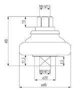
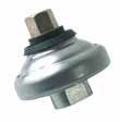

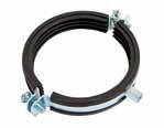


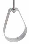
PAM Building - 141 05 PRODUCT CATALOG Quick hooking thanks to the opening a
SUSPENSION HOOKS «401» DN Tightening screw Weight Product code 50 M8 0.12 251179 75 M8 0.14 251180 100 M8 0.16 251191 125 M10 0.25 251192 150 M10 0.3 251193 200 M10 0.4 251194 250 M12 0.8 251195 300 M12 1 251196 RUBBER-LINED STEEL BRACKET DN Nut Tightening screw a Weight Product code 50 M8/10 Screw M6 ( Key of 10) 24 0.1 251197 75 M8/10 Screw M6 ( Key of 10) 24 0.3 251198 100 M8/10 Screw M8 ( Key of 13) 25 0.3 251199 125 M8/10 Screw M8 ( Key of 13) 25 0.4 251200 150 M10 Screw M8 ( Key of 13) 18 0.6 251201 200 M10 Screw M8 ( Key of 13) 19 1.6 251202 250 M12/16 Screw M12 ( Key of 19) 41 1.8 251203 300 M12/16 Screw M12 ( Key of 19) 41 2.9 251204 PAM ACOUSTIC DN Weight Product code 50 to 150 0.11 205113 “All dimensions are in mm and nominal weights are in kg” Quick hooking thanks to the opening
SUPPORTING & FIXING SYSTEMS
CANTILEVER ARMS
CANTILEVER ARM 41/21/2 LG 200 - DN 50 and 75
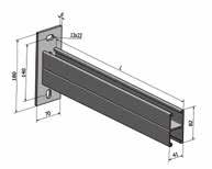
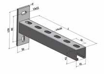
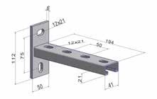
* F: Maximum load for 2 arms, when applied at mid-length of the arm (L/2), in daN
CANTILEVER ARM 41/ 41/ 2 LG 300 - DN 100 to 150
* F: Maximum load for 2 arms, when applied at mid-length of the arm (L/2), in daN
CANTILEVER ARM 41/ 82/ 2 LG 450 - DN 200 to 300
* F: Maximum load for 2 arms, when applied at mid-length of the arm (L/2), in daN

142 - PAM Building 05
galvanised steel DN L F* Weight Product code 50 200 150 0.5 251209 75
galvanised steel DN L F* Weight Product code 100 300 300 0.9 251210 125 150
galvanised
DN L F* Weight Product code 200 450 500 2.4 251211 250 300
steel
“All dimensions are in mm and nominal weights are in kg”
REINFORCEMENT FOR CANTILEVER ARM 41/82/2 LG 450 galvanised steel
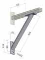
* F: Maximum load for 2 arms with reinforcement, when applied at mid-length of the arm (L/2), in daN
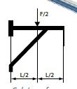
FIXATION BOLTS FOR CANTILEVER ARMS
STACK SUPPORT FIXING KIT
Galvanised zinc in combination with stack support bracket
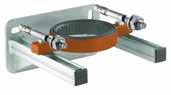

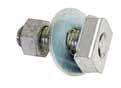
PAM Building - 143 05 PRODUCT CATALOG
DN L F* Weight Product code 200 450 800 2.4 251212 250 300
DN Weight Product code Cantilever arm 50 to 200 Reinforcement fixation M12x60 0.02 251208 Cantilever arm 250 and 300 M16 x70 0.03 252587
Hexagon bolt Stack support bracket Treaded plate Bolt anchor Stack support console DN Description Kit contents Plate dimension Hole spacing / Rail axial dimension Hole ø Weight Product code 50 FRK 50 SET 1 x Stack support console 262 SP45 1 x Stack support bracket DN 50 or DN 75 2 x Hexagon bolt M12x35 2 x Threaded plate GWP 45/12 Z 2 x Bolt anchor BZ 12-30/125 M 12 100x205x6 150 14 x 24 3.66 235621 75 FRK 75 SET 100x225x6 170 14 x 24 3.94 235622 100 FRK 100 SET 1 x Stack support console 315 SP45 1 x Stack support bracket DN 100 or DN 125 2 x Hexagon bolt M12x35 2 x Threaded plate GWP 45/12 Z 2 x Bolt anchor BZ 12-30/125 M 12 100x269x8 214 14 x 24 5.35 235623 125 FRK 125 SET 100x283x8 228 14 x 24 5.53 235624 “All dimensions are in mm and nominal weights are in kg”

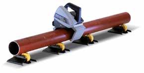
144 - PAM Building 05
EXACT SAW MACHINE Description DN Product code Exact PipeCut + Bevel 170E machine 50-150 280632 Disc bevel x140 (Exact PipeCut + Bevel 170E) 50-150 280633 Disc cut x140 (Exact PipeCut + Bevel 170E) 50-150 280634
TOOLS ACCESSORIES
PAINTS AND PROTECTION
After any cutting operation, the pipe ends must be protected by applying EXTREM 1. EXTREM 1 is a ready-to-use quick drying touch-up paint that air dries in 15 minutes. It is easily applied with a brush (included in the paint bucket)

TOUCH-UP SPRAY PAINT ( 400 ml )


PAM Building - 145 05 PRODUCT CATALOG
TOUCH-UP PAINT «EXTREM 1» RED Quantity Product code 250 ml 226788 500 ml 226962
Colour Product code "S range" red-brown color 257025 "Plus range" grey color 257027 "Residential ( Type R)" color 257028 "ITINERO" grey color 262704

DESIGN & INSTALLATION
06
RESISTANCE TO PRESSURE VENTILATION ACCESS TO NETWORK NETWORK SUPPORTING JOINTING METHODS CONNECTION TO OTHER MATERIALS MULTI-WASTE BURIED NETWORK EPAMS® GENERAL INSTALLATION INSTRUCTIONS DISCHARGE CAPACITY 148 156 160 162 168 170 175 176 178 183 186
RESISTANCE TO PRESSURE
REQUIREMENTS AND ADMISSIBLE PRESSURE LOAD
Standard requirements according to EN 12056
Gravity wastewater drainage systems and ventilation systems generally operate without pressure. Although this does not exclude the possibility of pressure arising in the systems under specific operating conditions.
EN 12056-1, Section 5.4.2 Water and Gas Tightness, states that drainage installations must be sufficiently water and gas tight to withstand operating pressure. Furthermore, EN 12056-5, Section 6.3 states, with respect to securing pipe systems: Non-anchored pipes must be secured and/or supported in such a manner that they cannot be disconnected during use. The arising reaction forces must be addressed. For the specific application of rainwater, EN 12056-3, Section 7.6.4. stipulates: Internal rainwater pipes shall be able to withstand the head of water likely to occur in the event of a blockage. The same precautions should be taken as on pipework liable to undergo accidental overloading: securing of bottom bends and joints with adequate grip collars or HP couplings.
Definitions
Fluid pressure is the force the fluid exerts per surface unit, perpendicular to this surface. Pressure change applied to the surface of an enclosed fluid is transmitted evenly and undiminished in all directions. Robust cast iron components can address any pressure hazard, so the couplings will be subjected to the strain. Couplings designed by PAM building are tested under hydrostatic pressure; only grip collars and autogrip collars are tested under end thrust forces.
NETWORK REQUIREMENTS AND ADMISSIBLE PRESSURE LOAD
In addition to the above standards, in a drainage network, pressure resistance requirements are dependent on:
• The height of the water column between the considered point of the network and the first outlet located upstream; generally speaking, we di erentiate waste and toilet networks from rainwater.
• The accidental risk of loading. The most frequent cases are due to occasional obstruction of downstream pipeline or saturation of the public network.
148 - PAM Building 06
WASTEWATER NETWORKS
Risk of pressure build-up with a low water column
Generally, the pressures that occur in wastewater drainage systems cannot exceed the pressure corresponding to the height of one storey, i.e. about 0.3 bar, as sanitary appliances on each floor serve as outlets in case of accidental overloading. The couplings we describe as “standard” (PAM Rapid and PAM R) meet these requirements.
Risk of pressure build-up with a high water column
In very rare cases, where domestic wastewater downpipes cross several levels of a building without any outlet, and where there would be a risk of accidental loading, the installation must comply with the recommendations applicable to rainwater networks.
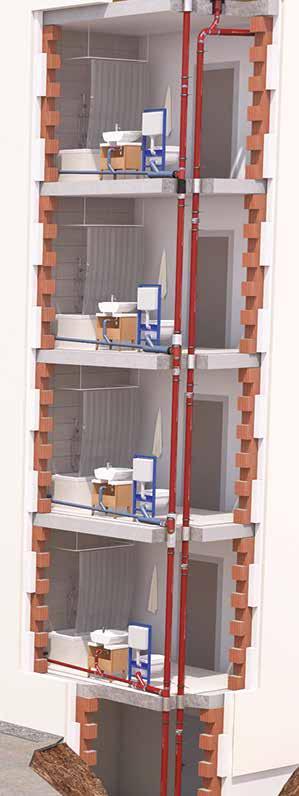
Wastewater outlets
PAM Building - 149 DESIGN & INSTALLATION 06
RAINWATER NETWORKS
Risk of pressure build-up with a low water column
Same as wastewater networks.
Risk of pressure build-up with a high water column
In some rare cases there could be a risk of accidental overloading. The pressure resistance required to ensure these systems remain leak tight and stable depends on the height of the water column liable to occur, and could call for high-pressure couplings able to withstand the resulting pressure (up to 10 bar).
Coupling solutions will be differentiated for building height between 0 to 30 m, 30 to 50 m, 50 to 100 m corresponding to different levels of pressure resistance requirements.
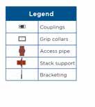
» Straight runs of the pipework
Straight runs between two fixed points and rigid bracketing do not experience exceptional forces. In case of accidental overloading, the couplings will only have to address hydrostatic pressure. Standard pressure couplings withstand up to 10 bar for DN50-DN125, up to 5 bar for DN150-DN200, up to 3 bar for DN250-DN300. High pressure couplings withstand up to 10 bar for DN100-DN400 and up to 6 bar for DN500 and DN600.
» Stack support
On vertical straight runs, stack support pipes should be installed to address the stacks’ weight. At the bottom of the stack, the first stack support pipe addresses both the pipes’ weight and the end thrust effort. For the last case, it is recommended that the support and fixings be adapted accordingly. We recommend positioning the first stack support pipe at the base of the first floor, and then every subsequent fifth floor, in the case of a standard average 2.5 m between floors, or more generally every 15 m
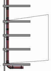
150 - PAM Building 06
Legend Add a stack support pipe every 15 m
RESISTANCE TO PRESSURE
» Changes of direction and specific elements (plugs, branches, bends)
End thrust forces can be exerted with changes of direction, gradient and specific components like branches and plugs. These forces have to be addressed to avoid any risk of the pipe system disconnecting or slipping using specific couplings.
It is considered that end-thrust effect must be addressed when drainage pipework may be exposed to an internal pressure higher than 0.5 bar.
In such conditions, the installation must be able to stay in place to perform its functions of water tightness, and mechanical stability, preventing any dislocation at the couplings. Grip collars and gripped HP couplings are part of the solutions to secure the network.
End thrust effect:
The result of the pressure forces exerted by a stationary fluid on the singular points of a pipe (or changes in direction), thus:
• Straight runs (pipes): the forces cancel each other out.
• Singular points (e.g. fittings): the resultant forces tend to dislocate the network.
The forces significantly increase with large pipe diameter as illustrated in the following table.
Thrust effect under 5 m water column (daN), corresponding to a 0.5 bar pressure.
It is considered that end-thrust effect must be addressed for:
1. Pipes laid under the groundwater table
2. Rainwater pipes or wastewater pipes running through several stories without outlets
3. HP>5 m as indicated on p.153
4. EPAMS – gripped collars or gripped couplings are mandatory until positive pressure is reached.
In these areas, the forces have to be addressed to avoid any risk of the pipe system disconnecting or slipping:
• Isolating the section suspected of having thrust forces between two fixed points, like stack support pipes.
• Adapting the joints (selection of couplings solutions) between these fixed points.
To address the thrust forces, other solutions can be used, like anchoring in concrete, or using dedicated bracketing systems.
PAM Building - 151 DESIGN & INSTALLATION 06
DN50 DN75 DN100 DN125 DN150 DN200 DN250 DN300 DN400 DN500 DN600 Expansion plugs or single long arm branches 10.5 22.5 41.5 63.5 90.5 157 269.5 387 666.5 1029 1475 Two 45° bends 14.5 32 59 95 127.5 225.5 382 544 941 1455.5 2087.5
RESISTANCE TO PRESSURE
COUPLING SELECTION ACCORDING TO LOADING RISKS
Couplings + Grip collars: performance


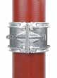
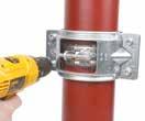
Note: under end thrust forces, where a coupling is secured with a grip collar, the maximum performance of both is limited by the weakest performance of the two products.
Focus on the PAM grip collars installation
Position the two half parts of the PAM grip collar uniformly so it encircles the pipe in parallel. The grip collars must be positioned so that the apertures fit over the coupling's fixing bolts and the teeth are directly located onto the pipe.
The assembly is completed when the external edges of the plates are in contact on both sides.

152 - PAM Building 06
Insert the four screws to fix the two parts together loosely.
Tighten the screws crosswise alternately so that the two plates are put in parallel with the same spacing.
DN600 DN50 6 DN500 DN400 10 DN300 3 DN250 DN200 5 DN150 DN125 10 DN100 DN75 DN50 +
GRIP HP couplings
PAM Rapid + grip collar
How to select the right coupling?
Before deciding which type of coupling to use it is important to answer the following questions:
• Wastewater or rainwater network?
Generally, the pressures that occur in wastewater drainage systems cannot exceed the pressure corresponding to the height of one storey, i.e. about 0.3 bar, as sanitary appliances on each floor serve as outlets in case of accidental overloading.
• Diameter of the pipes?
Thrust forces will be significantly larger for large diameter pipes and will have to be addressed with grip collars and HP couplings. Pressure resistance of couplings are specific for a given diameter. For DN 400 and larger only HP couplings are available.
• Height of the stack?
The higher the stack is, the higher the potential pressure build-up.
• Location of the coupling along the system?
Recommendations will change between 0 m < H ≤ 30 m, 30 m < H ≤ 50 m, and 50 m < H ≤ 100 m as the height of the water column will correspond to different pressure levels.
• Straight run or change of direction?
Thrust effort will have to be addressed at change of directions
Wastewater network DN 50 to DN300
Different coupling recommendations should be followed depending on the number of floors and the HP height. In case of several storeys without outlet, the installation must comply with the recommendations applicable to rainwater networks.
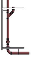
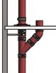
PAM Building - 153 DESIGN & INSTALLATION 06
Straight Run PAM Rapid S Change of direction HE ≥ 20 floors OR HP ≥ 5 m PAM Rapid S + grip collars or HP Gripped couplings Change of direction HE < 20 floors AND HP < 5 m PAM Rapid S HP* HP* Please add a stack support pipe every 15 m.
HP*: Height of the water column between the considered pipework point and the first upstream outlet
RESISTANCE TO PRESSURE
Rainwater network DN100 to DN125
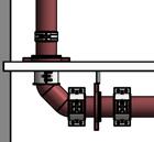
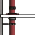
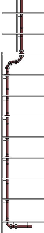
Straight Run H1 PAM Rapid S
Change of direction H1 PAM Rapid S + grip collars
Straight Run H2 PAM Rapid S
Straight Run H3 PAM Rapid S
Change of direction H3 PAM Rapid S + grip collars
154 - PAM Building 06
(50 m < H ≤ 100 m) (30 m < H ≤ 50 m) (0 m < H ≤ 30 m) H H3 H2 H1
Please add a stack support pipe every 15 m.
Rainwater network DN150 to DN200
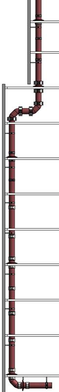
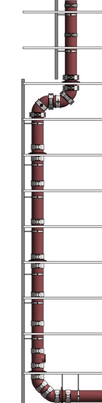
Rainwater network ≥ DN250
Change
PAM Building - 155 DESIGN & INSTALLATION 06
PAM
PAM HP
PAM
PAM
Straight Run H3
HP FLEX
FLEX Straight Run H2
Rapid S
HP FLEX
PAM
(DN250
PAM
DN400)
Straight Run H1
Rapid S PAM Rapid S
& DN300)
HP FLEX (≥
PAM
PAM
DN400)
of
H3 PAM HP GRIP PAM HP GRIP
of direction H1 PAM Rapid S + grip collars
Rapid S + grip collars (DN250 & DN300)
HP GRIP (≥
Change
direction
add a stack support pipe every 15 m.
Please
VENTILATION
A drainage pipe is normally at neutral air pressure compared to the surrounding atmosphere. When a column of wastewater flows through a pipe, it compresses air in the pipe, creating a positive pressure that must be released or it will push back on the waste stream and downstream traps’ water seals. As the column of water passes, air must flow in behind the waste stream or negative pressure (suction) results. The extent of these pressure fluctuations is determined by the waste discharge fluid volume.
The purpose of a ventilation stack is to control presure in the pipework to prevent foul air from the wastewater system entering the building. Below are some of the main configuration principles, but combinations and variations are often required (see standard EN 12056-2). The purpose of a ventilation stack is also to avoid accumulation of dangerous gases.
Black water and grey water can be drained either in separate or in a single discharge stack. The rules for duct sizing are different depending on the option selected.
Primary ventilated system configurations:
Control of pressure is achieved by air
flow in the discharge stacks. The soil stacks extend in main roof vents to above and out of the roof. Alternatively, air admittance valves may be used. They are pressure-activated, one-way mechanical vents, used in a plumbing system to eliminate the need for conventional pipe venting and roof penetrations.
156 - PAM Building 06
A single stack is still possible but design precautions must be taken to prevent selfsiphonage.
Secondary ventilated system configurations:
In buildings of three or more storeys, if the air pressure within the stack suddenly becomes higher than ambient, this positive transient could cause wastewater to be pushed into the fixture, breaking the trap seal.
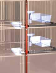
Vent stacks are put in parallel to waste stacks to allow proper venting and prevent such disorders. Air admittance valves may also be used in this configuration.
Under many building codes, a vent stack, a pipe leading to the main roof vent, is required to the draining fixtures (sink, toilet, shower stall, etc.).
To allow only one vent stack and therefore one roof penetration, as permitted by local building codes, sub-vents may be tied together and exit a common vent stack.
SINGLE STACK BRANCH
The single stack branch is a patented device made to allow wastewater drainage without secondary vent pipes. Provided the maximum number of connected sanitary appliances is respected, the single stack branch properly drains wastewater in a single stack, without vent pipes, whilst limiting the risks of self-siphonage. This device complies with standard EN 12056. Please consult local requirements for compliance with other regulations. The branch for a single downpipe allows wastewater drainage in a combined network without secondary ventilation according to EN 12056.
Field of use:
• Multi-connection of sanitary appliances for adjacent apartments, or sanitary blocks
• Compactness when space is limited
• No secondary vent pipes are required
Benefits: It simplifies plumbing by grouping pipework from 3 or 4 times more sources than a conventional installation. Maximum connections for each floor level: 2 toilets, 2 bathtubs and all the usual sanitary facilities for two apartments (sinks, basins, showers, etc.). The single stack branch is particularly suitable for narrow service shafts, hotel rooms, student apartments or any other building with adjacent sanitary blocks.
PAM Building - 157 DESIGN & INSTALLATION 06
VENTILATION
Operation features
• System under French Technical Approval
• Prevents excessive pressure variations in the stack system
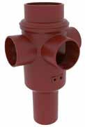
• Limits negative pressure by optimal venting and prevents self-siphonage
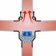
The single stack branch DN 100 main body is connected to the stack using standard couplings and a traditional jointing method. Their watertightness is ensured by the rubber gaskets which equip the S and Plus ranges offered by PAM Building.
The overall plumbing works shall be executed in compliance with standard EN 12056: the appliances shall be installed with traps in compliance with the specifications of the same standard.
Solution
The single stack branch exists as a long tai to allow connection to the main stack under the slab and thus facilitate installation either in new or renovation works. Three different products, 2 or 3 inlets:
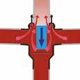
• Corner branch two inlets 88°
• Double branch two inlets 88°
• A consecutive branch, three inlets 88°
Rubber plugs with several pre-cut lids will allow one to three different connections.

158 - PAM Building 06
Owing to the special design of the branch, after a flush, the column of water is directed so that air can pass over the flow and naturally vent the stack.
Inside the branch, at the bottom of the body, a rubber deflector sprays the column of water to prevent draught or self-siphonage.
WATER FLOW AND AIR CIRCULATION, ACCORDING TO STANDARDS EN 12056-2
AND EN 12056-3
Wastewater and siphonic rainwater horizontal pipelines
The internal diameter of pipes cannot be reduced in the direction of the water fl ow, except in the case of pipework operating at full bore, under negative pressure such as in the EPAMS siphonic roof drainage system. The addition of branch connections, or changes of fall liable to increase the water flow rate, may require an increase in internal pipe diameter. This increase can be applied upstream of the new branch connection, using a tapered pipe (see p.98).
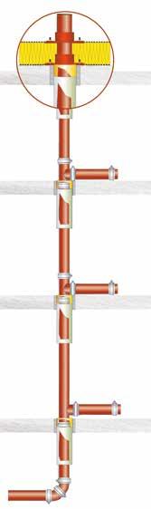
Gravitary rainwater horizontal pipelines
In horizontal and near horizontal pipelines, increases in size shall be installed so that the soffit is continuous, to prevent air from being trapped.
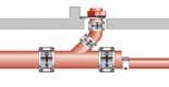
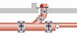
ROOF PENETRATION DEVICE
To secure roof watertightness, which is of crucial importance, the number of roof penetrations should be limited. PAM Building has designed a roof penetration device for its pipe systems that is watertight and quick to install.
The system was developed to facilitate the installation of completely watertight roof penetration for cast iron primary ventilation pipes or vent pipes. The flanged fittings clamp both the vapour barrier and the waterproofing layer.
The roof penetration device is a set of two ductile iron flanged fittings – one of the flanges is fixed, the second is movable – equipped with rubber gaskets. Rubber gaskets are available in EPDM or NBR quality where hydrocarbons may be present.
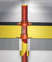
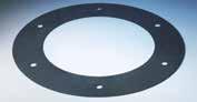
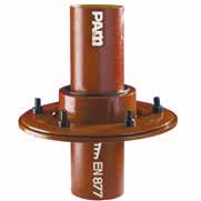
See product codes on p.103
The first flange fitting, installed above the roof, clamps the vapour barrier under the roof insulating layer, the second, above the insulating layer, clamps the waterproofing layer, whether it is polymer or bituminous.
PAM Building - 159 DESIGN & INSTALLATION 06
Rainwater (excluding EPAMS) Wastewater (+EPAMS) Water flow Waterproofing layer Roof insulating layer Vapour barrier Roof (corrugated steel roofing, concrete roofing, etc.) Water flow
ACCESS TO THE NETWORK
ACCESS TO THE PIPEWORK
Access to the pipework must be ensured so that tests, inspections and maintenance can be performed. Access may be obtained using a short access pipe.
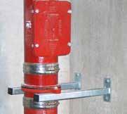
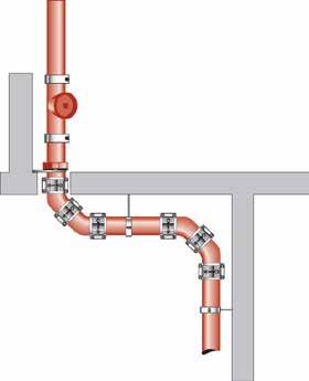
On downpipes
On horizontal collectors
On horizontal runs, the short access pipe will be installed in a slightly sloped position with respect to the pipe crown.
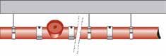
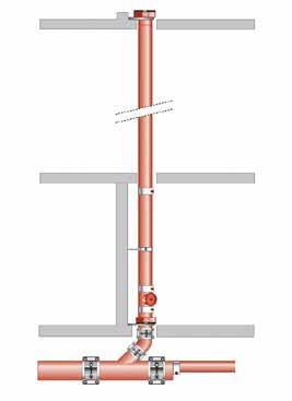
combines reliability, ease of use and operation safety:
The short
160 - PAM Building 06
access pipe
At the bottom of the stack
At changes of direction (stack offsets)

PAM Building - 161 DESIGN & INSTALLATION 06
BRACKETING: TECHNICAL
Pipe support except for the EPAMS® system
For cast iron, the bracketing system is designed to only carry the weight of the pipe and its content, which makes the specifiers’ design work easier.
Note: The technical specifications for threaded rods and metal brackets shall be established on this basis.
Bracketing recommendations for cast iron pipe system elements
Number of brackets
Consult local requirements for compliance
* For PAM-GLOBAL® pipes L ≥ 2.7 m installed outdoors - ** When the shape of the fitting permits it
It is also recommended to use one bracket per length or fitting (when the shape allows it, i.e. branches, etc.)
162 - PAM Building 06
Pipe weight in kg per metre 50 75 100 125 150 200 250 300 400 500 600 Empty pipe 4.5 6 8.5 12 14.5 23.5 33.5 44 60 82 107 Full pipe 6.5 10 18 5 32.5 55 88 121.5 185 278 390
Vertical run Pipes 1 (2)* Fittings** 1 Horizontal run Pipe length≥2 m 2 Pipe length<2 m 1 Fittings** 1
NETWORK SUPPORTING
Support for horizontal pipework
The general recommendation for horizontal pipework is two load bearing brackets per pipe.

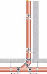
As an indication, they should be installed 0.75 m from each spigot so that, ideally, the distance between two brackets is 1.5 m. Installation shall respect a slight fall, around 1 or 2%, and 0.5% as a minimum, (0.5 cm per metre).
Support for vertical pipework
For vertical waste or rainwater stacks, the brackets aim to prevent the pipework from falling over. It is recommended that one bracket be fitted for each floor level.
Ideally, the bracket should be installed on the first third of the upper spigot, and even closer to a socket joint.
At the bottom of the stacks, the forces from the pipe’s weight and possible end thrust efforts will preferably be addressed through stack support pipes.
SPECIFIC BRACKETING FOR ACOUSTIC INSULATION
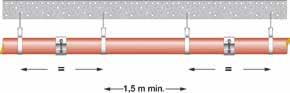

The evacuation of waste, soil and rainwater generates structure-borne and airborne sound between rooms and usually occurs as a result of a mixed flow, when the pipe is filled with water and air. In such circumstances a pipe will radiate noise outwards and transfer it to any lightweight ceilings, cupboards and similar areas wherever it makes contact.
PAM Acoustic dampener
All brackets within the PAM Building range meet the requirements of the most demanding standards. For high levels of acoustic performance, the standard steel brackets fitted with a new acoustic dampener should be used. The different assemblies have been tested to EN 14366: Laboratory measurements of noise from wastewater installations. The PAM acoustic dampener has been developed to meet the increasing demand for buildings to have a high level of acoustic performance above regulatory requirements.
PAM Building - 163 DESIGN & INSTALLATION 06 Horizontal collectors Bottom of stacks Vertical pipework Bracketing installations, openings and sealings are prohibited in pre-stressed girders. 0.75 m max. 0.75 m max. 0.75 m max. 0.75 m max. 0.75 m max. 0.75 m max.
noise as indicated on p. 46:
l/s < 10 dB(A)
< 10 dB(A)
Pipe installation fitted with acoustic dampener*
Structure-borne
2
4 l/s
* IPB 2019 tests results, installation according to EN 14366.
NETWORK SUPPORTING
Sound insulation in bracketing
Function
2 possibilities for fixing the PAM Acoustic Dampener on a Pipe Bracket:
1. Vertical lines: Each end of the acoustic dampener can be fixed to the bracket. For each 3 m of length minimum 1 pipe bracket must be used. For each pipe bracket 1 dampener must be used.
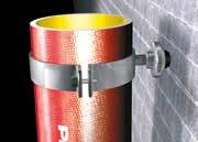
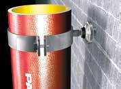
The weight of the pipes and the resulting water pressure must be absorbed by other devices: grip collars, stack supports, etc.
2. Horizontal lines: Each end of the acoustic dampener can be fi xed to the bracket. For each 3 m of length minimum 2 pipe brackets must be used. For each pipe bracket 1 dampener must be used.
With each type of fixation, the best effect can only be achieved if the components are neither deformed nor compressed.
Maximum horizontal load F per dampener: 100 daN.
1. Dampener – elastomer EPDM
2. M8-M10 – threaded nut; galvanised steel
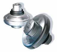
3. Stainless steel housing, A2
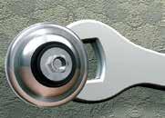
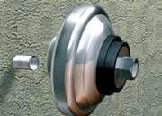
4. Thread connection with 17 mm key value ; galvanised steel
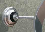
164 - PAM Building 06 1 4 2 3
The acoustic dampener is mounted between the wall or ceiling and the pipe bracket and dampens the noise generated in drainage pipe systems. It can be used with M8 and M10 thread rods.
Assembly
1. Fasten the PAM Acoustic Dampener to the thread in the wall with an open-end wrench
2. The second threaded rod connects the acoustic dampener and pipe bracket
3. Fix. Finished
F hor F hor Fhor Fhor 3 m 1 2 3
Prohibited assembly
This mounting leads to rotation / torsion of the elastomer, which means the dampener cannot work properly and the elastomer might be cut. Therefore, this type of fixation is not allowed.
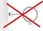
ATTENTION: This assembly causes the elastomer to twist
PIPEWORK STABILITY
Stack support pipe
Pipework is subject to different forces liable to affect its stability. Stack supports are cast iron components designed to address these efforts.
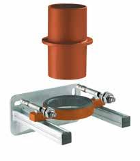
On straight runs, stack support pipes should be installed to address the pipes' weight. At the bottom of the stack, the first stack support pipe addresses both the pipes' weight and the end thrust effort. For the last case, it is recommended that the support and fixings be adapted accordingly.
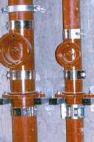
We recommend positioning the first stack support pipe at the base of the first floor, and then every subsequent fifth floor, in the case of a standard average 2.5 m between floors, or more generally every 15 m.
In the case of a wall or slab opening closed by mortar, thus constituting a fixed point, no stack support pipe is required.
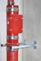
Stack support pipe and acoustic insulation
The support bracket of the stack support is covered with a rubber gasket to limit the transmission of structure-borne noise emitted by the drainage network at slab level.
During laboratory tests carried out in 2019*, a stack assembly including a stack support pipe on a console support and a rubber-lined bracket, both fixed to a wall with a surface density of 220 kg/m2, showed slightly better results than the same installation made with two fixings with rubber-lined brackets. In this particular installation, the use of stack support pipes does not affect acoustic performance.
*Tests carried out according to standard EN 14366.
PAM Building - 165 DESIGN & INSTALLATION 06
Rubber gasket Stack support console
NETWORK SUPPORTING
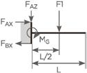
Admissible load for stack support console (see products on p.143)
Stack support pipe installed vertically
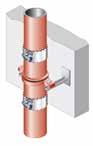
Either on cantilever arms or stack support consoles up to DN 125.
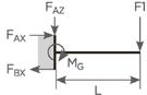
166 - PAM Building 06
Description Length (mm) Case 1 F1 (kN) Case 2 F2 (kN) Stack support console 262 FRK 50 Set 262 2.3 1.15 Stack support console 262 FRK 75 Set 262 2.3 1.15 Stack support console 315 FRK 100 Set 315 3.3 1.65 Stack support console 315 FRK 125 Set 315 3.3 1.65 Case 1 Case 2 F1 x L 2 FAZ = F1 MG = MG = FAZ = F2 F2 x L F2
Stack support pipe installed horizontally
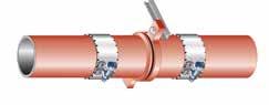
A wall bracketing system is available in mild steel, for use with stack support pipes and brackets. Admissible load for cantilever arms (see products on p.142-143)
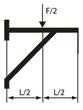

PAM Building - 167 DESIGN & INSTALLATION 06
Reference Diameters Length (L in mm) Admissible load (F in daN) Case 1 Cantilever arm 41/21/2 LG 200 50-75 200 150 Cantilever arm 41/41/2 LG 300 100 - 125 - 150 300 300 Cantilever arm 41/82/2 LG 450 200 - 250 - 300 450 500 Case 2 Reinforcement for cantilever arm 41/82/2 LG 450 200 - 250 - 300 450 800 Case 1 Case 2
JOINTING METHODS

STAINLESS STEEL COUPLINGS

ASSEMBLY AS A SLEEVE
PAM Rapid Couplings (S and INOX)

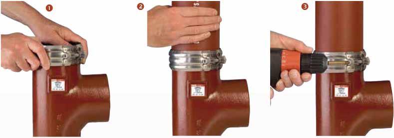
> DN 50 to 200
Couplings are supplied pre-assembled. The PAM Rapid from DN 50 to 200 is designed to be tightened to fully closed, there is no need to check the torque.
They can be assembled in two different ways, depending on whether an open strap is required.
Standard assembly:
1. Open the stainless steel strap.
2. Slide the stainless steel strap loose around the first pipe component.
3. Push the sealing gasket onto the component spigot so it abuts on the central register of the gasket.
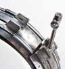
4. Push the second component into the sealing gasket, so that it abuts on the central register.
5. Bring the steel strap over the sealing gasket.
6. Tighten the bolt with a ratchet spanner or a power tool applying the following tightening torque: DN 250 and DN 300 = 25 N.m.


168 - PAM Building 06
Push the supplied assembled coupling onto the pipe spigot so that it abuts on the central register of the elastomer gasket.
Push the next pipe spigot into the other end of the coupling.
Tighten the screw to “zero gap” position, i.e. fully closed, with a ratchet spanner or electric screwdriver.
> DN 250 to 300
1 2 3 1 2 3 4 5 6
Open strap assembly: An open strap is sometimes required to facilitate access: stack installation, etc.
1 - Push the rubber gaskets onto the spigot ends top and bottom, ensuring the central registers are abutted against each spigot edge.
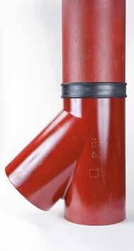
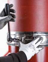

2 - Twist the stainless steel strap to ease the wrapping around the pipe components.
3 - Clip the bolt and loosely assemble the coupling around the gasket.
4 - Check the alignment of the assembly before tightening the bolt with a ratchet spanner or a power tool, applying the following tightening torque: DN 250 and DN 300 = 25 N.m.
ATTENTION:
Wherever couplings may be subject to end thrust forces, they must be secured with grip collars. See p.152 for installation details.
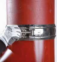
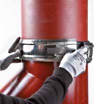
PAM Building - 169 DESIGN & INSTALLATION 06
1 2 3 4 3
TO OTHER MATERIALS
BRANCH CONNECTIONS TO SMALL DIAMETER WASTE PIPES
PAM KONFIX, the easiest solution
The easiest way to connect cast iron systems to other drainage materials is to use rubber connectors or plugs. Flexible couplings and stepping rings are also available to facilitate connections where variances in diameters have to be compensated for.

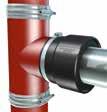
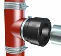
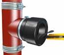
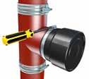
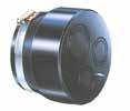
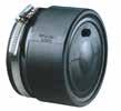
Rubber transition connectors PAM KONFIX and PAM KONFIX-Multi are used to connect waste pipes made from other materials (steel or plastics) to a PAM cast iron pipe system.
EPDM plugs
The plugs can be pierced to the appropriate groove from 32 mm up to 54 mm waste connections and the center disc torn out where required.

170 - PAM Building 06 CONNECTION
1. Insert the PAM KONFIX rubber connector loosely onto the pipe until the stop point is reached. Then secure to the pipe by tightening the hose clamp screw.
2. Cut the pre-cut rubber to size with a knife and remove the lid. WARNING: Do not cut too deep as you may damage the lip seal inside.
3. Mark the insert depth on the connecting pipe. Apply a lubricant and push in. The assembly is complete.
4. The connecting steel pipe illustrated here is only an example. The PAM KONFIX rubber connectors can be used to connect all waste pipe materials to the PAM cast iron systems.
Konfix
Konfix-Multi
EPDM plug 3 inlets
DN 50 DN 75 DN 100 DN 100 4 3 2 1
EPDM plugs 1 or 2 inlets
PAM MULTIQUICK, TRANSITION CONNECTOR
To connect PAM cast iron pipes with an outside diameter of 109-112 mm (tolerance range for PAM cast iron pipes DN 100) to other rigid materials with an outside diameter from 72-110 mm.
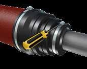
To connect PAM cast iron pipes with an outside diameter of 109-112 mm to waste pipes with an outside diameter up to 115 mm maximum. The connection is made with two hose clamps both suitable to address larger diameter tolerances.
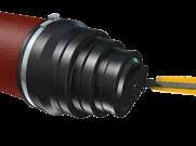
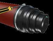
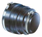
1. Push the open end of the PAM MULTIQUICK connector over the pipe end and place the hose clamp to its tightening position.
2. Then use a knife to cut open the pre-cut lid to the corresponding outside diameter of the connecting waste pipe. Then push the second hose clamp loose over the connecting rubber end.
3. Push the connecting pipe into the PAM MULTIQUICK connector and tighten the hose clamp in the right position. Ensure that the sealing zones (face ends of pipes or fittings) are clean: remove paint flakes and cement residues. The hose clamps should only be tightened manually with a screwdriver to avoid any damage to the PAM MULTIQUICK rubber connector.
PAM Building - 171 DESIGN & INSTALLATION 06
1 2 3
TO OTHER MATERIALS
CAST IRON TO CAST IRON AND CAST IRON TO OTHER MATERIALS
PAM cast iron connections to other materials may often be required in new construction projects or for renovation. Different solutions can be used with products from our catalog (see figures below). Depending on the outside diameters, solutions exist for compensation. If you are unsure of the circumference of the material being connected, you can use a circumference tape. The range of tolerance of the different joints can help you find the required solution. The table below lists the solutions for connecting PAM cast iron to the most frequently encountered material.
*PAM Rapid can be used for type 1 installation but it may create an aesthetics default (stepping ring can exceed the width of the coupling).
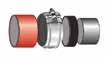


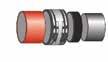
172 - PAM Building 06 CONNECTION
DN* Existing network material OD** (mm) Circumference (mm) Admissible tolerance of couplings (mm) Coupling type Product code Reference diagram DE Perimeter 50 S Range, Plus range 58 182 55-60 172-188 PAM Rapid S 210424 5 PVC 50 157 55-60 49-52 172-188 153-163 PAM Rapid S + SR 210424 156399 1 HDPE 50 157 55-60 49-52 72-188 153-163 PAM Rapid S + SR 210424 156399 1 75 S Range, Plus range 83 260 81-86 254-270 PAM Rapid S 210426 5 Old cast iron 64 201 81-86 62-65 58-79 254-270 194-204 182-248 PAM Rapid S + SR 210426 156495 1 77 241 81-86 75-79 58-79 254-270 235-248 182-248 PAM Rapid S + SR 210426 156494 1 90 282 75-90 235-282 AC 255300 3 PVC 75 235 81-86 75-79 58-79 254-270 235-248 182-248 PAM Rapid S + SR 210426 156494 1 80 251 75-79 235-282 AC 255300 3 HDPE 63 197 81-86 62-65 58-79 254-270 194-204 182-248 PAM Rapid S + SR 210426 156495 1 75 235 81-86 75-79 58-79 254-270 235-248 182-248 PAM Rapid S + SR 210426 156494 1 *DN=Nominal Diameter **OD=External Diameter
Max. Pressure 1.5 bar/ Stainless steel 304 5. A = B Max. Pressure 0.6 bar / Stainless steel 304 Max. Pressure 1.5 bar / Stainless steel 304
1. PAM Rapid* + Stepping ring (SR)
3. Adapting collar = AC 4. Adapting collar (AC) + Stepping ring (SR)
2. Adapting joint = AJ
PAM Building - 173 DESIGN & INSTALLATION 06 DN* Existing network material OD** (mm) Circumference (mm) Admissible tolerance of couplings (mm) Coupling type Product code Reference diagram DE Perimeter 100 S Range, Plus range 110 345 107-112 335-351 PAM Rapid S 210427 5 Old cast iron 91 285 107-112 90-93 78-106 335-351 282-292 244-332 PAM Rapid S + SR 210427 156555 1 104 326 100-115 78-106 314-361 244-332 AC 155002 3 118 370 110-121 345-380 AC TXB10NP01 3 Ductile iron 118 370 110-121 345-380 AC TXB10NP01 3 Fibre cement 115 361 110-121 345-380 AC TXB10NP01 3 PVC 100 314 107-112 99-102 78-106 335-351 310-320 244-332 PAM Rapid S + SR 210427 156635 1 110 345 107-112 335-351 PAM Rapid S 210427 5 HDPE 90 282 107-112 89-92 78-106 335-351 279-288 244-332 PAM Rapid S + SR 210427 156555 1 110 345 107-112 335-351 PAM Rapid S 210427 5 Steel 114 358 100-115 314-361 AC 155002 3 Sandstone 132 414 110-115 130-145 345-361 408-455 AJ Contact us 2 Concrete 136 427 110-115 130-145 345-361 408-455 AJ Contact us 2 125 S Range, Plus range 135 424 133-138 417-433 PAM Rapid S 210428 5 Old cast iron 118 370 110-125 121-136 345-387 408-427 AJ Contact us 2 145 455 130-150 408-471 AC TXB12NLOG 3 Ductile iron 144 452 130-150 408-471 AC TXB12NLOG 3 Fibre cement 141 442 130-150 408-471 AC TXB12NLOG 3 PVC and HDPE 125 392 133-138 123-127 417-433 386-398 PAM Rapid S + SR 210428 156778 1 Steel 139 436 130-150 408-471 AC TXB12NLOG 3 Sandstone 159 499 121-136 144-160 379-427 452-502 AJ Contact us 2 150 S Range, Plus range 160 502 158-164 496-514 PAM Rapid S 210429 5 Old cast iron 145 172 455 540 130-145 155-170 150-175 408-455 486-534 471-549 AJ AC 155003 TXB15NM0J 2 3 Ductile iron 170 534 150-175 471-549 AC TXB15NM0J 3 Fibre cement 166 521 150-175 471-549 AC TXB15NM0J 3 PVC 140 439 130-145 155-170 408-455 486-534 AJ 155003 2 PVC and HDPE 160 502 158-164 496-514 PAM Rapid S 210429 5 Steel 168 527 150-175 471-549 AC TXB15NM0J 3 Sandstone 186 584 144-160 170-193 452-502 533-606 AJ Contact us 2 Concrete 190 596 144-160 170-193 452-502 533-606 AJ Contact us 2
*DN=Nominal Diameter **OD=External Diameter
CONNECTION TO OTHER MATERIALS
CAST IRON TO CAST IRON AND CAST IRON TO OTHER MATERIALS
174 - PAM Building 06 DN* Existing network material OD** (mm) Circumference (mm) Admissible tolerance of couplings (mm) Coupling type Product code Reference diagram DE Perimeter 200 S Range, Plus range 210 659 207-213 650-668 PAM Rapid S 210430 5 Old cast iron 172 540 170-193 210-235 534-606 659-738 AJ 155004 2 197 618 200-225 192-201 628-706 603-631 AC + SR TXB20NN0K 4 218 684 200-225 628-706 AC TXB20NL0K 3 225 706 Ductile iron 222 697 200-225 628-706 AC TXB20NL0K 3 Fibre cement 218 684 200-225 628-706 AC TXB20NL0K 3 PVC and HDPE 200 628 207-213 198-202 649-668 621-634 PAM Rapid S + SR 210430 157000 1 Steel 219 688 200-225 628-706 AC TXB20NL0K 3 Sandstone 242 760 204-219 238-254 640-687 747-797 AJ Contact us 2 Concrete 244 766 204-219 238-254 640-687 747-797 AJ Contact us 2 250 S Range, Plus range 274 860 271-276 850-868 PAM Rapid S 228759 5 Old cast iron 242 760 240-265 260-285 753-832 816-894 AJ TXB25NQ0K 2 279 876 260-285 816-894 AC 143192 2 Ductile iron 274 860 271-276 850-868 PAM Rapid S 228759 5 Fibre cement 274 860 271-276 850-868 PAM Rapid S 228759 5 PVC and HDPE 250 785 271-276 248-252 850-868 778-791 PAM Rapid S + SR 228759 157085 1 Steel 273 857 271-276 850-868 PAM Rapid S 228759 5 Sandstone 296 929 285-310 270-290 894-973 847-910 AC + SR TXB25NQ0L 4 300 S Range, Plus range 326 1024 323-328 1014-1031 PAM Rapid S 228771 5 Old cast iron 312 331 980 1039 310-335 973-1051 AC TXB30NN02 3 Ductile iron 326 1024 323-328 1014-1031 PAM Rapid S 228771 5 Fibre cement 329 1033 310-335 973-1051 AC TXB30NN02 3 PVC and HDPE 315 989 310-335 973-1051 AC TXB30NN02 3 Steel 324 1017 323-328 1014-1031 PAM Rapid S 228771 5 Sandstone 350 1099 320-340 335-360 1005-1068 1051-1130 AC + SR TXB30NQ0M 4 Concrete 374 1174 310-335 350-375 973-1051 1099-1178 AJ Contact us 2
*DN=Nominal Diameter **OD=External Diameter
Multi-Waste Manifold Connector
The multi-waste manifold simplifies waste plumbing by grouping all associated pipework from various sources such as sinks, basins, bidets, urinals and showers to one internal point above the finished floor level. The manifold will permit the connection of three 32/38 mm copper/plastic waste inlets to any new or existing 100 mm diameter pipe stack and three 50 mm copper/plastic waste inlets to a 150 mm diameter pipe stack.
The manifold main body is connected to the stack using standard coupling. On the 100 mm manifold, to achieve a 32 mm waste connection, remove the 38 mm inner rubber ring by using the outer ring (for waste pipe maximum lengths see EN 12056-2). Pipework connecting discharge appliances to a manifold should be designed not to cause self-siphonage.
Fixing instructions
1. Cut the appropriate groove for 32 mm or 38 mm waste connections (100 mm manifold only), remove the grommet and tear out the centre disk where required.
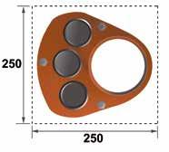
2. Apply an appropriate silicone grease (not provided) to the outside of the grommet and re-fit into the manifold ensuring the retaining groove of the grommet is located correctly in the casing.
3. Lubricate the pipe ends and insert into the grommet with a rotational movement. Pipe ends may be chamfered for ease of insertion.
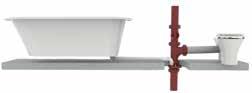
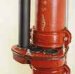

4. Any grommet not fitted with a waste pipe must also follow instruction 2 above.


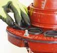
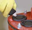
PAM Building - 175 DESIGN & INSTALLATION 06
Typical Manifold Application
MULTI-WASTE
BURIED NETWORK
BURIED PIPE SYSTEMS
The Plus range pipes can be used in below-ground applications. Buried pipes are subject to mechanical strain due to the weight of the ground and possible wheel loading when laid under an area where traffic circulates.
The mechanical performance of buried pipework is to be considered like a pipe/soil system: the interaction of the pipes with the surrounding soils depends on their stiffness or flexibility, and the type of laying condition selected.
The choice of bedding and backfilling depends on the depth at which the pipes have to be laid, and the size and strength of the pipes. Standard EN 1610 “Construction and testing of drains and sewers” applies to drains normally buried in the ground and normally operating under gravity.
The hypothesis for rigid pipes retained for the calculation of admissible depth of cover is set out below.
Installation parameters are established according to:
• Soil type (see groups below)
• Quality of compaction of the embedment
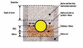
• Behavior of the pipe (rigid for cast iron)
• Presence of wheel loads or not
• Particular conditions (groundwater table, etc.)
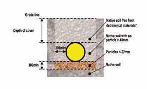
Backfilling recommendations from DN 100 to DN 300, with or without traffic loads (according to EN 1610)
Two main solutions have been retained from the EN 1610 recommendations, taking into account both ease of installation and knowledge from experience of rigid pipe systems. For compaction, the most adverse hypothesis was retained.
These solutions maximise the advantage obtained from cast iron’s mechanical properties: depth of cover it can withstand, possible backfilling with native soil removed, thereby limiting damage to the environment, etc.
Case no.1
Case no.2
176 - PAM Building 06
Dimensions are in mm * Detrimental materials = stones, tree roots, rubbish, organic material, clay lumps (>75 mm), snow and ice.
DN 100 to DN 300 Young's modulus 110,000 N/mm2 Poisson’s ratio 0.25 Max. stress 350 N/mm2 Strain coe cient 1.5 Buckling coe cient 2.5 Geometric defect 1.2 + DN 2,000 mm
Based on our experience in buried pipe systems and the French origin of our company, we have applied the French Fascicule 70 calculation model (recommendations for sewage pipe systems according to the pipe material).
The table below gives values for depths of cover according to the Fascicule 70 calculation, considering rigid pipes.
** Does not take into account the frost-free arrangements.
(1) The calculation allows shallower depth of cover, but this figure includes a safety margin / ground surface proximity and related hazards.
Other precautions
• Clearance at each joint between the couplings and the granular bed to allow sufficient space, and to prevent the pipe from resting on the joints. (see EN1610 §6.5)
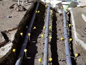
• Testing for pipe system leak tightness according to EN 1610 §12
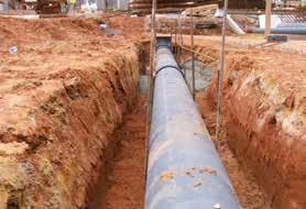
• Identification of the pipework with a netting for example
• Furthermore, check that these specifications do not contravene other local or national regulations or recommendations for installation
For any other case, other diameters or buried systems under the bottom slab, please contact our technical support team: tcbatiment.sgpam@saint-gobain.com - Tel:+33 (0)3 66 74 00 89
Where the pipe system is to be set in concrete, a minimum 2.5 cm width of concrete on every side has to be respected because during and after its curing, the concrete will be subject to shrinkage and carbonation.
To reduce the natural rigidity of the concrete and its strain, a suitable flexible joint can be installed at intervals. This could be made of a compressible material (e.g. expanded polystyrene), be placed next to a pipe joint, and conform to the full cross section of the concrete. (See Fig). Refer to local best practice.
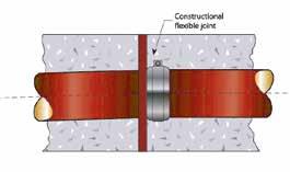
Furthermore, the pipe system should not be in contact with the concrete's metal reinforcements.
Surround should not be carried out until the pipework has been tested and inspected.
PAM Building - 177 DESIGN & INSTALLATION 06
Depth of cover values (m) Without tra c loads With tra c loads Solution 1 Min.** 0.3(1) 1 Max. 3.2 2.4 Solution 2 Min.** 0.3(1) 0.3 Max. 6 (or 9) 6 (or 9)
The system is under French Technical Approval 5.2/14-2386_V2 CSTB.
EXPLANATIONS OF SIPHONIC SYSTEMS
1. No rain
2. Rainfall starts at low intensity – Drainage is performed by gravity flow
3. Continuous flow is achieved according to the rainfall intensity and roof area drained
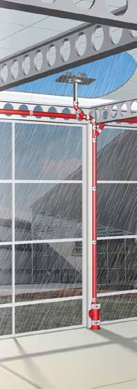
4. Rainfall intensity increases to the maximum DRI–Flow continues by gravity until the maximum value is reached
5. No more air entering the system – Kinetic and pressure energies enhance the absorbing capacity quickly to the maximum design flow rate
6. Rainfall intensity stabilises to max. value => absorbing siphonic flow rate is maintained
7. Rainfall intensity decreases – Flow comes back to gravity system
8. Rainfall intensity stabilises to low value => absorbing gravity flow rate is maintained
9. No more rain – the rooftop surface is emptying
EPAMS ® DESIGN SERVICE
A siphonic roof drainage system is truly an «engineered system» which must be designed with careful and expert analysis. The pipework design is the key factor for performance and operational safety.
PAM Building sales staff, trained in the EPAMS® system, first evaluate your roof drainage project. When feasibility is confirmed, a technical team designs both the technical study and network sizing using the dedicated EPAMS® software.
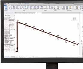
178 - PAM Building 06
The EPAMS® system is a combination of cast iron pipes, fittings and accessories, jointed with PAM Rapid couplings or couplings able to withstand a negative pressure of -700 mbar.
Outlet Flowrate (l/s) Q Siphonic by design Q Max gravitary Q Gravitary Rainfall intensity (l/min.m2) Time (s) Gravity ow Siphonic ow Gravity ow Imax = DRI I<max gravity EPAMS®
The system must always be properly balanced and the flow velocity controlled. To protect the lifespan of the EPAMS® siphonic systems, the PAM Building design maintains that the dynamic pressure within the system should never exceed 5 bar.
Trained staff specifically in charge of your design will handle your siphonic project until the work’s acceptance; each change to the plans results in the need for a new study.
Before the acceptance of the work, PAM Building or a delegated third party checks on site that the installation fully complies with the last study isometric drawings; any modification to an EPAMS® pipework route at the installation stage requires further approval from PAM Building.
This thorough management of the EPAMS® projects – feasibility study, project follow-up and control after installation completion – ensures the EPAMS® system’s efficiency and provides the project manager with total peace of mind.
INSTALLATION
The EPAMS® outlets are easy to install. The installation has to be done in accordance with best practice and the Technical Approval requirements.
PAM Building EPAMS® 100% metal outlets fully guarantee mechanical strength and durability. They fully comply with EN 1253 on each specific point: flow capacity, watertightness, solidity, mechanical strength, heat resistance and climatic stresses (resistance to UV radiation).
The grating and anti-vortex mechanism are made in one piece. This allows quick removal with no risk of mistakes at reassembly, easy intervention and maintenance.
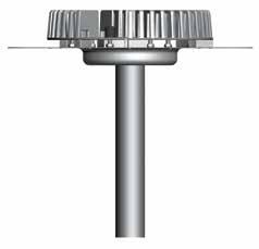
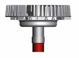
EPAMS® siphonic roof drainage pipework
An EPAMS® pipework consists of one or several horizontal pipes without fall connected to a downpipe: horizontal runs and stacks are made of S range cast iron components. The joints are generally made with PAM Rapid or equivalent couplings.
• Connection of the roof outlets to the pipe system: Depending on the job site constraints, the connection can be made flat or vertical.
EPAMS 100% METAL OUTLETS
The EPAMS® outlets are made of 3 different parts:
• The Anti-Vortex mechanism, aluminium grating. Bolted on the bowl, it is the same for all the outlets.
• An identical stainless steel bowl for all the outlets, on which different components can be assembled depending on the field of use.
• A stainless steel tail available in four DN: 50 – 75 – 100 – 125.
PAM Building - 179 DESIGN & INSTALLATION 06
Anti-vortex mechanism Cast aluminium Bowl Stainless steel Tail Stainless steel 40 400 14,5 70 THICKNESS 0,4 Ø 192 Ø 340 Square plate 500 x 500 50 mm min. Minimum dimension flat branching DN 50 Roof outlet DN 50 Roof outlet DN 50 Roof outlet Minimum dimension vertical branching
• Decompression zone:
Before connecting to the sewer main, siphonic systems have to run by gravity again.
At the end of the downpipe, the bottom pipe increases in diameter – generally two extra diameters – causing decompression and reducing the flow velocity.
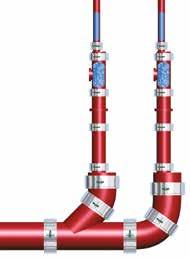
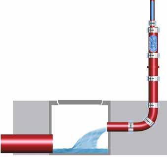

Case no.1
Vertical decompression zone in the last metre of the stack
Tapered pipe reducer
Short access pipe
Stack support pipe
Tapered pipe reducer
Gravity bend
Manhole cover
Case no.2
Decompression zone directly connected to a manhole
If the manhole is connected close to the stack, the short access pipe is optional. The potential high discharge rates shall be taken into account for the manhole sizing.
Stack support pipe
Case no.3 Horizontal decompression zone
This solution must be considered before the design study.
Short access pipe
Stack support pipe
Tapered pipe reducer
Tapered pipe reducer
Gravity drain
180 - PAM Building 06
Sewer main
EPAMS®
• Pipe support
Stack support pipes are installed at the bottom of stacks to address forces due to changes in the stream flow systems. Every 15 metres is the general requirement.
• Pipe brackets:
Owing to the high discharge rates, rubber-lined steel brackets are compulsory. Two brackets per pipe length shall be installed for horizontal or vertical pipework. It is also recommended to use one bracket per length or fitting (when the shape allows it, i.e. branches, etc.).
For the EPAMS® siphonic system, only round full and rubber-lined brackets shall be used.
For brackets fixed to plain threaded rods, the distance between the bearing structure (concrete slab, steel frame, etc.) and the axis of the pipe shall not exceed 500 mm. If this maximum distance cannot be respected, the rigidity of the fixings should be increased (triangulation, steel knee brace).
Check local requirements for compliance.
Specific points of the network
• Gripped couplings

On EPAMS pipework, grips collars are specified on couplings where they will withstand dislocation forces.
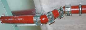
- Horizontal pipe connected to the outlet when the expected pressure is over 0.5 bar or -0.5 bar.
- The negative pressure will be highest at the head of the stack (down to -0.9 bar); the couplings there will be systematically installed with grip collars.
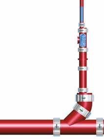
- Change of direction: at changes of direction on stacks and low collectors, the couplings will be gripped. Where a change of direction will be added or removed, PAM Building will carry out a new study taking the new head loss into account.
- The decompression zone is subject to turbulences, and subsequently, every component at the bottom of the stack, before the return to the gravity flow system, will be gripped.
Number Pipe length > 2 m 2 Pipe length < 2 m 1 Fittings* 1
Tapered pipe reducer
Short access pipe
Stack support pipe
Tapered pipe reducer
Gravity bend
PAM Building - 181 DESIGN & INSTALLATION 06
* When the shape of the fitting permits of brackets Vertical run Pipes 2 Fittings* 1 Horizontal run
EPAMS®
• Reduction of flow sections
Achieving balance of potential energy and head losses on the pipework can require a reduction in the nominal diameters to increase head losses.

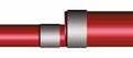

The regulations state that reducing the nominal diameter (DN) of discharge pipes is prohibited in the direction of flow except for siphonic systems like EPAMS® (EN 12056-3 § 7,6,5) where it could be useful to control the pressure level. Increases and reductions of nominal diameters are made with the tapered pipe reducer. On horizontal runs, the pipe reducer will be installed so that the pipe invert is continuous.
Keeping the roof outlets clean is key to keeping an EPAMS® siphonic system in good working order.
The Technical Approval recommends they should be cleaned at least twice a year.
Any element like plant matter (leaves, twigs, etc.) or debris from the surroundings can end up on rooftops, and mustbe regularly cleared away to prevent clogging of the pipework or EPAMS® outlets. Maintenance cleaning frequency will largely depend on the building's environment. For buildings surrounded by trees and gardens, inspections will be done more frequently and the maintenance rate will be higher than the standard twice yearly requirement.
For all types of roof outlets, the cleaning process must be carried out as described opposite.


182 - PAM Building 06
Ensure the leafguard grid is in place. Clean the leafguard grid.
Remove the nut caps. Unscrew the nuts and lift the leafguard grid to remove it. water flow direction
Clean the inside of the roof outlet bowl.
MAINTENANCE GENERAL FEATURES
GENERAL INSTALLATION INSTRUCTIONS
CUTTING, COATING, PAINTING, TESTING AND REPAIRING


INSTALLATION FEATURES
Preparation
Cast iron pipe systems for drainage mainly consist of spigot pipes - generally supplied in 3 m lengths - and fittings of various shapes (bends, branches, etc.). The cast iron pipes can be cut to length. Where pipes are cut on site, ends shall be cut clean and square with burrs removed, and then re-coated with the adequate EXTREM 1 touch-up paints (see p.145), or other repair products recommended by PAM Building.
RECOMMENDED
RECOMMENDED to cut the pipe
Cutting techniques
Pipes can be cut easily and quickly using either of the following methods. Cutting procedures must comply with the safety guidelines provided in the cutting tool manufacturer’s operating manual.


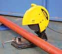
PAM Building - 183 DESIGN & INSTALLATION 06
Extrem 1 Touch-up paint Cordless Drill Exact saw Chop saw A - T-Box Spanner B - 13 mm Deep Socket C - Allen Key Socket Adapter D - Ratchet Spanner A B C D
TOOLS
Exact
Powered disc cutter S and Plus ranges DN50 DN75 DN100 DN125 DN150 DN200 DN250 DN300 DN400 DN500 DN600
Pipe cutter
saw
GENERAL INSTALLATION INSTRUCTIONS
CUTTING, COATING, PAINTING, TESTING AND REPAIRING
The Exact saw : the ultimate and fast solution for cutting 50-200 mm cast iron (see p.144)
• Easy, secure and effortless cutting for use on construction sites
• Wide range of applications and dimensions
• No rework necessary – accurate cutting
• Suitable for clamping joints
• Reduction in tool costs
• Reduction in sparks – may not require hot works permit

Coating cut ends
Pipe ends needed to be recoated with touch-up paint.
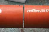
We recommend protecting the cut ends with EXTREM 1 (see p.145), a new quick drying touch-up paint that air dries in 15 minutes.
Overpainting method
The acrylic paint on the pipes is a primer which can be over painted with most top coats. Finishing paint is needed where the pipework is visible, indoor or outdoor. What types of paint can be used? Any alkyd resin or glycerophtalic paint designed for metal care and suitable for the requirements of the local environment.
The system should be gently rubbed down with suitable abrasive paper to provide a good adhesion key for the finishing coating. Where the finishing paint is to be used onzinc-coated pipes to rejuvenate them, rub them down gently to remove possible zinc salts.
Where incipient rust has already appeared on cast iron products, corrosion inhibitors can be used before painting. Some existing metal finishes, including anti-corrosive pigment, can be applied directly to rust.
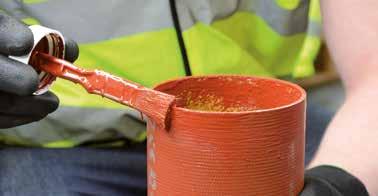
184 - PAM Building 06
MODIFICATIONS TO AN EXISTING INSTALLATION
Typical example of a spigot system
1. Measure the length of the branch, adding a further 15 mm in total to allow for the coupling’s central register top and bottom.
2. Make sure existing pipework is adequately supported from above.
3. Mark the pipe position for cutting.
4. Cut the pipe using a powered disc cutter or wheel cutter and remove sharp edges.
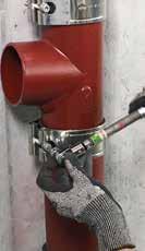
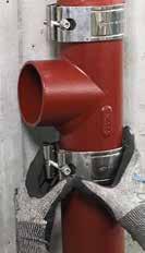
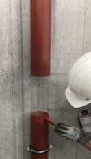
5. Coat the cut ends with the appropriate touch-up product (epoxy coating).
6. Push the rubber gaskets onto the spigot cut ends top and bottom, ensuring the central registers are abutted against each spigot edge.
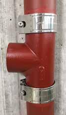
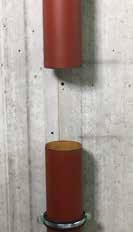
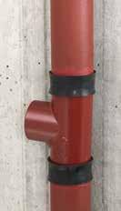
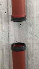
7. Position the fitting in the stack within each rubber gasket abutting against the central registers.
8. Loosely assemble the coupling around each gasket.
9. Check alignment of assembly before tightening the bolts to the recommended level, depending on the coupling's technical recommendations.
10. Test the new stack for successful joints.
For more information please contact our technical department: e-mail: tcbatiment.sgpam@saint-gobain.com tel: +33 (0)3 66 74 00 89
PAM Building - 185 DESIGN & INSTALLATION 06
X = fitting + 15 mm X
DISCHARGE CAPACITY
APPLICATION
For the dimensioning of rainwater and wastewater systems, the nominal sizes can be determined using the dimensioning tables in the appendix of DIN EN 12056. These tables only represent the discharge capacity of the smallest permissible inner diameter of the values specified.
If the pipe material is known at the latest during the execution planning, the specific discharge capacities should be determined for a differentiated calculation on the basis of the actual internal diameter of the respective drainage pipe system should be used for a differentiated calculation.
EXAMPLE OF WASTEWATER PIPE FILLING
LEVEL H/D = 1.0 WITH SLOPE 1 cm/m
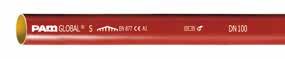
(see also J cm/m in the following table)
CALCULATE THE SLOPE:
186 - PAM Building 06
SLOPE IN % = HEIGHT DIFFERENCE LENGTH OF THE TRACK • 100
DN PAM drainage pipes DIN 1986-100, A3 DIFFERENCE 100 3,0 l/s 2,5 l/s +20% 125 5,3 l/s 3,9 l/s +36% 150 8,5 l/s 7,7 l/s +10%
PAM Building - 187 DESIGN & INSTALLATION 06
Filling level 50% (h/di=0.5) DN 75 di = 75 DN 100 di = 103 DN 125 di = 127 DN 150 di = 152 DN 200 di = 200 DN 250 di = 263 DN 300 di = 314 J Q v Q v Q v Q v Q v Q v Q v cm/m l/s m/s l/s m/s l/s m/s l/s m/s l/s m/s l/s m/s l/s m/s 0.5 0.9 0.4 2.1 0.5 3.7 0.6 6.0 0.7 12.5 0.8 25.8 1.0 41.3 1.1 0.6 1.0 0.4 2.3 0.6 4.1 0.6 6.6 0.7 13.7 0.9 28.3 1.0 45.3 1.2 0.7 1.1 0.5 2.5 0.6 4.4 0.7 7.1 0.8 14.8 0.9 30.6 1.1 48.9 1.3 0.8 1.1 0.5 2.7 0.6 4.7 0.7 7.6 0.8 15.8 1.0 32.7 1.2 52.3 1.4 0.9 1.2 0.6 2.9 0.7 5.0 0.8 8.1 0.9 16.8 1.1 34.7 1.3 55.5 1.4 1.0 1.3 0.6 3.0 0.7 5.3 0.8 8.5 0.9 17.7 1.1 36.6 1.3 58.5 1.5 1.1 1.4 0.6 3.2 0.8 5.5 0.9 8.9 1.0 18.6 1.2 38.4 1.4 61.4 1.6 1.2 1.4 0.6 3.3 0.8 5.8 0.9 9.4 1.0 19.4 1.2 40.1 1.5 64.2 1.7 1.3 1.5 0.7 3.4 0.8 6.0 1.0 9.7 1.1 20.2 1.3 41.8 1.5 66.8 1.7 1.4 1.5 0.7 3.6 0.9 6.3 1.0 10.1 1.1 21.0 1.3 43.4 1.6 69.3 1.8 1.5 1.6 0.7 3.7 0.9 6.5 1.0 10.5 1.2 21.7 1.4 44.9 1.7 71.8 1.9 1.6 1.6 0.7 3.8 0.9 6.7 1.1 10.8 1.2 22.4 1.4 46.4 1.7 74.1 1.9 1.7 1.7 0.8 3.9 0.9 6.9 1.1 11.1 1.2 23.1 1.5 47.8 1.8 76.4 2.0 1.8 1.7 0.8 4.1 1.0 7.1 1.1 11.5 1.3 23.8 1.5 49.2 1.8 78.7 2.0 1.9 1.8 0.8 4.2 1.0 7.3 1.2 11.8 1.3 24.5 1.6 50.6 1.9 80.8 2.1 2.0 1.8 0.8 4.3 1.0 7.5 1.2 12.1 1.3 25.1 1.6 51.6 1.9 82.9 2.1 2.5 2.0 0.9 4.8 1.2 8.4 1.3 13.5 1.5 28.1 1.8 58.0 2.1 92.8 2.4 3.0 2.2 1.0 5.3 1.3 9.2 1.5 14.8 1.6 30.8 2.0 63.6 2.3 101.7 2.6
DISCHARGE CAPACITY OF PAM PIPES ACCORDING TO EN 877 AND DIN 19522
di = INTERNAL DIAMETER J = GRADIENT Q = VOLUME FLOW RATE V = FLOW VELOCITY
DISCHARGE CAPACITY
188 - PAM Building 06 DISCHARGE
Filling level 70% (h/di=0.7) DN 75 di = 75 DN 100 di = 103 DN 125 di = 127 DN 150 di = 152 DN 200 di = 200 DN 250 di = 263 DN 300 di = 314 J Q v Q v Q v Q v Q v Q v Q v cm/m l/s m/s l/s m/s l/s m/s l/s m/s l/s m/s l/s m/s l/s m/s 0.5 1.5 0.5 3.6 0.6 6.2 0.7 10.1 0.7 20.8 0.9 43.1 1.1 68.9 1.2 0.6 1.7 0.5 3.9 0.6 6.8 0.7 11.0 0.8 22.9 1.0 47.2 1.2 75.5 1.3 0.7 1.8 0.5 4.2 0.7 7.4 0.8 11.9 0.9 24.7 1.1 51.1 1.3 81.6 1.4 0.8 1.9 0.6 4.5 0.7 7.9 0.8 12.7 0.9 26.4 1.1 54.6 1.3 87.3 1.5 0.9 2.1 0.6 4.8 0.8 8.4 0.9 13.5 1.0 28.0 1.2 58.0 1.4 92.6 1.6 1.0 2.2 0.7 5.1 0.8 8.8 0.9 14.3 1.1 29.6 1.3 61.1 1.5 97.6 1.7 1.1 2.3 0.7 5.3 0.9 9.3 1.0 15.0 1.1 31.0 1.3 64.1 1.6 102.4 1.8 1.2 2.4 0.7 5.5 0.9 9.7 1.0 15.6 1.2 32.4 1.4 67.0 1.6 107.0 1.8 1.3 2.5 0.7 5.8 0.9 10.1 1.1 16.3 1.2 33.8 1.4 69.7 1.7 111.4 1.9 1.4 2.6 0.8 6.0 1.0 10.5 1.1 16.9 1.2 35.0 1.5 72.4 1.8 115.6 2.0 1.5 2.7 0.8 6.2 1.0 10.9 1.1 17.5 1.3 36.3 1.5 74.9 1.8 119.7 2.1 1.6 2.7 0.8 6.4 1.0 11.2 1.2 18.1 1.3 37.5 1.6 77.4 1.9 123.7 2.1 1.7 2.8 0.9 6.6 1.1 11.6 1.2 18.6 1.4 38.6 1.6 79.8 2.0 127.5 2.2 1.8 2.9 0.9 6.8 1.1 11.9 1.3 19.2 1.4 39.8 1.7 82.1 2.0 131.2 2.3 1.9 3.0 0.9 7.0 1.1 12.2 1.3 19.7 1.5 40.9 1.7 84.4 2.1 134.8 2.3 2.0 3.1 0.9 7.2 1.2 12.5 1.3 20.2 1.5 41.9 1.8 86.6 2.1 138.3 2.4 2.5 3.4 1.0 8.0 1.3 14.0 1.5 22.6 1.7 46.9 2.0 96.9 2.4 154.7 2.7 3.0 3.8 1.1 8.8 1.4 15.4 1.6 24.8 1.8 51.4 2.2 106.1 2.6 169.6 2.9 di = INTERNAL DIAMETER J = GRADIENT Q = VOLUME FLOW RATE V = FLOW VELOCITY
CAPACITY
OF PAM PIPES ACCORDING TO EN 877 AND DIN 19522
PAM Building - 189 DESIGN & INSTALLATION 06
CAPACITY
Filling level 100% (h/di=1.0) DN 75 di = 75 DN 100 di = 103 DN 125 di = 127 DN 150 di = 152 DN 200 di = 200 DN 250 di = 263 DN 300 di = 314 J Q v Q v Q v Q v Q v Q v Q v cm/m l/s m/s l/s m/s l/s m/s l/s m/s l/s m/s l/s m/s l/s m/s 0.5 1.8 0.4 4.2 0.5 7.4 0.6 12.0 0.7 24.9 0.8 51.6 1.0 82.6 1.1 0.6 2.0 0.4 4.7 0.6 8.2 0.6 13.2 0.7 27.4 0.9 56.6 1.0 90.5 1.2 0.7 2.1 0.5 5.0 0.6 8.8 0.7 14.2 0.8 29.6 0.9 61.2 1.1 97.8 1.3 0.8 2.3 0.5 5.4 0.6 9.4 0.7 15.2 0.8 31.6 1.0 65.4 1.2 104.6 1.4 0.9 2.4 0.6 5.7 0.7 10.0 0.8 16.2 0.9 33.6 1.1 69.4 1.3 111.0 1.4 1.0 2.6 0.6 6.0 0.7 10.6 0.8 17.1 0.9 35.4 1.1 73.2 1.3 117.1 1.5 1.1 2.7 0.6 6.3 0.8 11.1 0.9 17.9 1.0 37.1 1.2 76.8 1.4 122.8 1.6 1.2 2.8 0.6 6.6 0.8 11.6 0.9 18.7 1.0 38.8 1.2 80.3 1.5 128.3 1.7 1.3 2.9 0.7 6.9 0.8 12.1 1.0 19.5 1.1 40.4 1.3 83.6 1.5 133.6 1.7 1.4 3.1 0.7 7.2 0.9 12.5 1.0 20.2 1.1 41.9 1.3 86.7 1.6 138.7 1.8 1.5 3.2 0.7 7.4 0.9 13.0 1.0 20.9 1.2 43.4 1.4 89.8 1.7 143.6 1.9 1.6 3.3 0.7 7.7 0.9 13.4 1.1 21.6 1.2 44.9 1.4 92.8 1.7 148.3 1.9 1.7 3.4 0.8 7.9 0.9 13.8 1.1 22.3 1.2 46.3 1.5 95.6 1.8 152.9 2.0 1.8 3.5 0.8 8.1 1.0 14.2 1.1 22.9 1.3 47.6 1.5 98.4 1.8 157.3 2.0 1.9 3.6 0.8 8.3 1.0 14.6 1.2 23.6 1.3 48.9 1.6 101.1 1.9 161.7 2.1 2.0 3.7 0.8 8.6 1.0 15.0 1.2 24.2 1.3 50.2 1.6 103.8 1.9 165.9 2.1 2.5 4.1 0.9 9.6 1.2 16.8 1.3 27.1 1.5 56.2 1.8 116.1 2.1 185.6 2.4 3.0 4.5 1.0 10.5 1.3 18.4 1.5 29.7 1.6 61.6 2.0 127.2 2.3 203.3 2.6
DISCHARGE
OF PAM PIPES ACCORDING TO EN 877 AND DIN 19522
di = INTERNAL DIAMETER J = GRADIENT Q = VOLUME FLOW RATE V = FLOW VELOCITY

GENERAL TERMS & CONDITIONS OF SALE
07
GENERAL TERMS & CONDITIONS OF SALE
Article 1 - GENERAL PROVISIONS
These Terms and Conditions of Sale (“T&Cs”) cancel and replace those previously communicated. They apply to any order placed by a client (“Client”) to SAINT-GOBAIN PAM BÂTIMENT, a company organized and existing under the laws of the French Republic with a share capital of 6 812 970,75 € with its registered office at 21 avenue Camille Cavallier in Pont-à-Mousson (54700), France registered with the Register of Commerce of Nancy under number 799 283 882 (“PAM BUILDING”), for the sale of PAM BUILDING’s goods and services (“Products”).
Any order made by the Client implies its adherence to these terms and conditions of sale. The Client’s purchasing conditions shall not take precedence over these terms and conditions of sale unless first agreed in writing by PAM BUILDING. Any prior written acceptance of the latter by PAM BUILDING may only be intended, where applicable, to supplement these conditions in the event of their silence.
PAM BUILDING reserves the right to amend its T&Cs at any time, the applicable T&Cs being those in force on the date of the order sent by the Buyer.
Article 2 - ORDERS - ACCEPTANCE
2.1 - Each order for Products must be identified as an order and must include the necessary information for its processing, in particular sufficient accurate information on the branding, delivery and listing of the range, in order to allow PAM BUILDING to process this order as best possible. In case of insufficient or inaccurate information, PAM BUILDING may delay the shipping date of Products, without prejudice to any other solution.
2.2 - Orders do not become firm and final until PAM BUILDING has issued an acknowledgement of receipt. No modification or cancellation of an order shall be taken into account after the issue of the acknowledgement of receipt of the order.
Unless otherwise provided between the parties, PAM BUILDING’s silence does not constitute acceptance of an order.
Article 3 - PRICING
3.1 Products are sold under the conditions and for the prices currently applicable on the effective delivery date or, where there is an offer, the prices indicated in relation to it, insofar as the order is received by PAM BUILDING within the period of validity of that offer.
3.2 Where PAM BUILDING issues an offer, prices are firm throughout the duration of the offer or for a maximum duration of two (2) months following the issue date of that offer. After this period, price increases may be applied.
3.3 Prices may be modified by PAM BUILDING at any time with a notice period of thirty (30) days.
3.4 Unless specifically agreed, prices are expressed in euros, net, excluding VAT. If applicable according to the Products destination, these prices are billed after application of value added tax at the rate in force. PAM BUILDING shall be entitled to recover any tax, duty or increase arising from a change to regulations or legislation, from its entry into force.
Article 4 - DELIVERY
4.1 Our delivery times are mentioned as an indication, and correspond to our best estimate. Delivery times are only firm when they are expressly classified as such in the order acknowledgement.
4.2 Non-respect of the indications relative to the delivery time does not authorise the Client to cancel their order, to delay payment beyond the agreed conditions or to withhold or offset any part of it.
4.3 No late penalty may be claimed from PAM BUILDING if it has not been expressly agreed with regard to its principle and its terms in the order acknowledgement.
4.4 PAM BUILDING is not responsible for breached delivery times where:
> the Client has not respected the payment conditions; or
> where information to be provided by the Client has not arrived within the required time;
4.5 The transfer of ownership of the Products to the Client is conditional upon payment of the price in full.
4.6 Risk is transferred under the conditions defined by the chosen Incoterm (Incoterms published by Paris International Chamber of Commerce in force on the effective delivery date, the “Incoterms”) or where Products are customised and covered by the carrier.
4.7 In the absence of specific conditions agreed beforehand and confirmed in the order acknowledgement by PAM BUILDING, the Products are sold Free Carrier (FCA - Incoterms® 2020) from PAM BUILDING’s shipping site.
4.8 For any exit from the European Union territory made by the Client or the forwarding agent designated by the Client, as proof of exit, the Export Control System (“ECS”) of exit must be sent to PAM BUILDING. In the event that the ECS cannot be provided, the Client or its forwarding agent may send to PAM BUILDING, the Bill of lading for shipment by sea or the Airway Bill for shipment by air or the CMR Way Bill with receiver’s signature and stamp or the Delivery note with receiver’s signature and stamp.
Article 5 - INSPECTION
5.1 Products are inspected in the factory according to PAM BUILDING’s quality control procedures and the standards in force.
5.2 In cases where a special inspection has been agreed, by the Client or an organisation representing it, the inspectors in charge are advised of the dates and times in which inspections must normally take place.
192 - PAM Building 07
Article 6 - TRANSPORT
6.1 Where the Client organises transport itself, it assumes the restrictions of adapting vehicles to Products and the obligation to make an appointment 48 hours in advance. Otherwise, the delivery cannot be loaded.
6.2 The Client is responsible for unloading operations carried out under its control. In this regard, the Client must ensure respect for safety conditions on site and provide suitable means to allow unloading in the best possible safety conditions. In particular, in case of a delivery by truck crane, the Client shall assist the driver by separating pipes and packages on the ground. The Client must establish a safety protocol with the carrier prior to unloading.
6.3 In case of lost, damaged or missing Products observed upon delivery, the Client shall take recourse against the carrier, stating its reservations on the transporter’s delivery form. It will confirm these reservations with the carrier, by registered letter with acknowledgement of receipt, addressing its claim with supporting documentation within 3 business days following receipt of the Products.
Article 7 - PAYMENT CONDITIONS
7.1 Unless otherwise indicated, payments are made at the address stated on the invoice, within forty-five (45) days from end of the month following the invoice issue date, independently from the date of receipt of the Products by the Client.
7.2 Drafts accepted must be returned within 10 days following their issuance. This deadline also applies to means of payment issued by the Client.
7.3 Any payment made after the payment date stated on the invoice shall allow the billing of (i) late penalties at a rate equal to the interest rate applied by the European Central Bank to its refinancing operation plus 10 percentage points and (ii) a fixed charge for recovery costs, of a sum of €40; PAM BUILDING reserves the right to seek additional compensation, upon justification, in the event that its recovery costs exceed this amount.
7.4 In case of non-payment of an outstanding invoice, all of the invoices in arrears shall become immediately payable. In addition, PAM BUILDING reserves the right to suspend orders in progress, without prejudice to damages and interest.
7.5 No claim by the Client may invoke the modification, delay or suspension of payments due, or authorise it to offset or deduct payments against those owed to PAM BUILDING. Any offsetting or deduction not agreed beforehand shall constitute a payment incident justifying the application of the above measures.
7.6 In the event of a significant change to the Client’s legal or financial situation, affecting PAM BUILDING’s assessment of its solvency, or in case of an excessive outstanding amount, PAM BUILDING reserves the right even after partial execution of an order to either demand guarantees or cancel the outstanding orders.
Article 8 - GUARANTEE FOR PRODUCTS
8.1 Without prejudice to the measures to be taken with regard to the carrier, claims in relation to the non-conformity of delivered Products with those listed on the order acknowledgement must be submitted in writing within 3 days from receipt of the Products. After this time, no claims shall be accepted.
8.2 PAM BUILDING guarantees the Client against hidden defects that may affect the sold Products. If the Client detects a manufacturing fault in the Product, in its opinion constituting a hidden defect, it must send a claim to PAM BUILDING immediately.
8.3 The implementation of the guarantee for conformity and hidden defect is conditional upon these faults being jointly observed and acknowledged as effectively attributable to PAM BUILDING. The Client will provide all justifications as to the reality of the faults found. It shall facilitate PAM BUILDING in observing these faults and remedying them. The Client shall abstain from interfering with the Products.
8.4 An observation of the fault will then be conducted, within 1 month -with everything as is, except in case of force majeure - in a report in the presence of PAM BUILDING’s representatives.
8.5 If the existence of a fault is jointly found and recognised by PAM BUILDING as being effectively attributable to it, PAM BUILDING shall assume the repair of the Product or supply a replacement of the Product previously delivered, and the corresponding shipping costs.
8.6 The Client is obliged under its exclusive responsibility to respect the indications given by PAM BUILDING as well as the industry standards for the compliant handling and use of the Products as well as all technical instructions.
8.7 The guarantee given is excluded in case of:
> apparent defect, or that which a professional would discover;
> defect and/or deteriorations caused by natural wear or by an external accident;
> modification of the Product not provided for or specified by PAM BUILDING;
> defect and/or deteriorations caused by a compatibility fault against Products not provided by PAM BUILDING;
> non-respect by the Client of the indications concerning handling, fitting, use and maintenance of Products as well as industry standards; > force majeure or similar event.
8.8 The guarantee given by PAM BUILDING is for 12 months from delivery. Interventions conducted in relation to the guarantee shall not result in extending this period.
ARTICLE 9 - LIABILITY
9.1 PAM BUILDING warrants that its Products comply with their specifications at the date at which they are placed at Client’s disposal. Specifications, performances and technical characteristics stated in catalogs, technical brochures and any other commercial documentation and packaging are subject to revision at any time without any prior notice to the Client. Characteristics and colours of PAM BUILDING’s Products have an indicative value due to their nature of manufacturing.
9.2 Client recognizes that he is aware of the technical characteristics of the Products as well as their conditions of use and application, defined in particular by the rules of the art and the current technical documentations. For the avoidance of doubt, the Client shall conduct prior and sufficient tests to verify that the Products meet its requirements.
9.3 PAM BUILDING’s liability is limited to the supply of the Products complying with PAM BUILDING’s specifications to the exclusion of any consequence of an improper, careless or inadequate use which remains under the exclusive responsibility and liability of the Client.
9.4 PAM BUILDING’s liability is limited to the replacement or reimbursement of the Products proved to be defective, without indemnification or compensation relating to transport or labour costs to be due to the Client. No responsibility or liability shall be accepted for any statement, representation, warranty or otherwise made by any of PAM BUILDING representative, agent or distributors.
Article 10 - INDUSTRIAL PROPERTY
The plans, models, studies, results of trials, catalogs, notices and all commercial and technical documents disseminated on any support whatsoever, by PAM BUILDING are the exclusive property of PAM BUILDING. As a result, the Client is prohibited from making any copy whatsoever without PAM BUILDING’s prior agreement.
Article 11 - MANUFACTURE - RECOMMENDATION
11.1 The weights and dimensions of Products indicated on PAM BUILDING’s documents are theoretical in value. PAM BUILDING reserves the right to make any modification to the information given in its documentation.
PAM Building - 193 GENERAL TERMS & CONDITIONS OF SALE 07
11.2 The documents regarding the handling, storage, fitting, use and maintenance of Products are provided by PAM BUILDING free of charge, at the Client’s request. The Client remains solely responsible for compliance with the health and safety conditions of these various operations and the implementation of the Products according to industry standards.
PAM BUILDING reserves the right to modify the data given in its documentation at any time. It is the Client’s responsibility to verify their validity with PAM BUILDING.
Article 12 - PACKAGING
12.1 The Products’ packaging is designed so as to satisfy the requirements of transportation.
12.2 Packaging and dunnage not billed for by PAM BUILDING will be recovered upon delivery.
Article 13 - CONFORMITY OF EXPORTING CONTROLS
The Client undertakes to respect all applicable laws, particularly those concerning export controls. If, at any time, a new law or regulation enters into force rendering the execution of PAM BUILDING’s obligations impossible or illegal, PAM BUILDING shall be entitled to cancel the order and terminate the contractual relationship, without any liability with regard to the Client.
Article 14 - PERSONAL INFORMATION
14.1 PAM BUILDING, as a controller, carries out a computerised processing of its clients personal information to place orders and make deliveries.
14.2 Personal information collected in this context
(Client’s company name, first and last name of PAM BUILDING’s contact at the Client’s, email address, business telephone or fax number) is

strictly necessary for the T&Cs execution and enable PAM BUILDING to manage the order, delivery, invoicing and collection.
14.3 Personal information is kept for the entire duration of the commercial relationship and within the limits of the applicable laws.
14.4 PAM BUILDING’s customer service, commercial, invoicing and collection departments, as well as its subcontractors responsible for delivery and sending invoices, receive this data.
14.5 In accordance with applicable regulations regarding personal information protection, the Client has a right to access, to correct, to erase and to object to the use of his or her personal information, which the Client may exercise, by sending an email to: privacycontact.sgpambatiment.fr@ saint-gobain.com, or by writing to : SAINT-GOBAIN PAM BÂTIMENT – Privacy Correspondent – 21 avenue Camille Cavallier, 54700 Pont-à-Mousson, France.
14.6 For more information about the way PAM BUILDING processes personal information, the Client may consult the web page «Your data and your rights» on PAM BUILDING’s websites: www. pambuilding.fr (France website) and www.pambuilding.com (Export website).
14.7 If the Client considers, after having contacted PAM BUILDING, that his/her rights are not respected or that the processing of his/her personal information by PAM BUILDING does not comply with the applicable rules, the Client shall be entitled to file a claim with the French personal data protection supervisory authority (CNIL).
Article 15 - CONFIDENTIALITY
The Client undertakes not to disclose to a third party, in whole or in part, any document, data, or
information exchanged, in any form and of any nature whatsoever relating to the order and/or the Products without the prior written consent of PAM BUILDING. This commitment shall apply for the entire duration of the order and for five (5) years from the last delivery of Products under said order.
Article 16 - FORCE MAJEURE
16.1 PAM BUILDING is not responsible for cases of force majeure. Force majeure is understood to mean any cause independent of the will of PAM BUILDING, which would render the performance of its contractual obligations impossible, and affect the manufacture, shipping and delivery of Products. Cases of force majeure are considered to include disruptions to production and/or delivery resulting from a war (declared or not), strike, lock-out, accident, fire, flooding, natural disaster, epidemics, pandemics, interruption or delay in delivery, shortage of materials and/or raw materials, embargoes, and settlements, of any nature whatsoever.
16.2 In the event of force majeure, PAM BUILDING shall have a reasonable extra period of time in which to execute its obligations.
Article 17 - APPLICABLE LAW - ALLOCATION OF JURISDICTION
In the event of a dispute as to the formation, performance or interpretation of the sales contract, the Nancy courts shall be solely competent even in case of multiple defendants, guarantee claims or proceedings in chambers. These T&Cs shall be subject to French law to the exclusion of its conflict-of-law rules.
194 - PAM Building 07
PAM Building Sales enquiries: +33 (0) 383 807 650 / 653 / 654 Technical enquiries: +33 (0)3 66 74 00 89 tcbatiment.sgpam@saint-gobain.com Visit our website: www.pambuilding.com
SIMPLE IDEAS
SUSTAINABLE RESULTS
100% PAM Building System - 100% Guaranteed Performances
Only the exclusive combination of PAM Building products (pipes, fittings, couplings) and
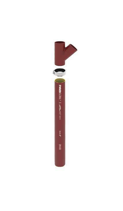
the respect of the implementation rules guarantees you results in accordance with the test reports from PAM Building and allows you to benefit from the 10 years warranty.

Photos: DR, ©Istock, ©Shutterstock, ©Saint-Gobain PAM Bâtiment. All rights reserved
• The photos and illustrations used in this document are not contractual. Any reproduction, even partial, of the diagrams, photos and texts in this document is prohibited without the authorization of Saint-Gobain PAM Bâtiment (Law of March 11, 1957). Realisation: Delicate essence www.delicate-essence.fr
196 - PAM Building PAM Building 21 avenue Camille Cavallier - BP 129 • 54705 • PONT-À-MOUSSON Cedex • France Tel : +33(0)3 83 80 67 89 www.pambuilding.com April
2023
