What is President Donald Trump’s agenda?
Will US Steel pivot to greener fields, asks Akira Kanno.
IDOM Consulting examines the available technologies.
Tenova’s and Ori Martin’s Lighthouse Project.


What is President Donald Trump’s agenda?
Will US Steel pivot to greener fields, asks Akira Kanno.
IDOM Consulting examines the available technologies.
Tenova’s and Ori Martin’s Lighthouse Project.
Metals offers the entire steel value chain an exceptional opportunity for curbing their CO2 emissions.
The unique combination of its historic and recently developed product portfolio, make John Cockerill one of the industry’s most relevant suppliers of equipment for both the hot and cold phase of the steelmaking and processing industry.
Our three distinct business segments are addressing todays and tomorrow’s challenges supporting sustainable and green steel production:
Our new upstream offering related to DRI (Direct Reduced Iron), EAF (Electric Arc Furnaces) technologies and the use of hydrogen in steelmaking. Next to offering indirect electrification (DRI-EAF&H2-DRI-EAF),John Cockerill is also working on Volteron®: A first-of-a-kind iron reduction and steel processing route via direct cold electrolysis. This CO2 free steelmaking process, has been co-developed with the world’s leading steelmaker ArcelorMittal.
Regrouping our historical downstream product portfolio, this segment also includes:
¡ the Jet Vapor Deposition (JVD®) technology set to replace today’s hot-dip or electro galvanizing processes. This novel high-productivity vacuum coating technology provides previously unknown coating flexibility and possibilities, all while offering lower CAPEX and OPEX.
¡ our E-Si® equipment & processing lines specifically designed to produce high-quality Non-Grain Oriented (NGO) steel in response to the need for electrical steel meeting precise metallurgical properties, essential to support the shift towards green mobility.
This segment not only embraces all services and after-sales activities but will be strongly focusing on downstream furnace electrification (reheating and processing line furnaces), as well as hydrogen combustion, and the optimization of plant operations, including energy audits and the modernization of steel production equipment and installations.


EDITORIAL
Editor Matthew Moggridge
Tel: +44 (0) 1737 855151
matthewmoggridge@quartzltd.com
Assistant Editor
Catherine Hill
Tel:+44 (0) 1737855021
Consultant Editor
Dr. Tim Smith PhD, CEng, MIM
Production Editor Annie Baker
Advertisement Production Carol Baird
SALES
International Sales Manager
Paul Rossage paulrossage@quartzltd.com
Tel: +44 (0) 1737 855116
Sales Director
Ken Clark
kenclark@quartzltd.com
Tel: +44 (0) 1737 855117
Managing Director
Tony Crinion
tonycrinion@quartzltd.com / Tel: +44 (0) 1737 855164
Chief Executive Officer
Steve Diprose
SUBSCRIPTION
Jack Homewood
Tel +44 (0) 1737 855028 / Fax +44 (0) 1737 855034 Email subscriptions@quartzltd.com
Steel Times International is published eight times a year and is available on
subscription. Annual subscription: UK £226.00 Other countries: £299.00
2 years subscription: UK £407.00 Other countries: £536.00
3 years subscription: UK £453.00 Other countries: £625.00 Single copy (inc postage): £50.00 Email: steel@quartzltd.com
Digital subscription: (8 times a year) - 1 year: £215.00 - 2 years: £344.00
3 years: £442.00. Singe issue: £34.00
Published by: Quartz Business Media Ltd, Quartz House, 20 Clarendon Road, Redhill, Surrey, RH1 1QX, England. Tel: +44 (0)1737 855000 Fax: +44 (0)1737 855034 www.steeltimesint.com
Steel Times International (USPS No: 020-958) is published monthly except Feb, May, July, Dec by Quartz Business Media Ltd and distributed in the US by DSW, 75 Aberdeen Road, Emigsville, PA 17318-0437. Periodicals postage paid at Emigsville, PA. POSTMASTER send address changes to Steel Times International c/o PO Box 437, Emigsville, PA 17318-0437. Printed in England by: Stephens and George

Ltd • Goat Mill Road • Dowlais • Merthyr Tydfil • CF48 3TD. Tel: +44 (0)1685 352063
Web:

www.steeltimesint.com
Latin America update 80 years of Acesita/Aperam, Pt.4.
India update Floodgates are opened.
AIStech 2025 (5-8 May)
We examine a few of the new products to be found in Nashville, TN.
Steelmaking in the hydrogen era.
North American markets
Trump’s environmental agenda.
Vacuum-tank degassing offers better performances.
Nippon’s US Steel acquisition.
Decarbonization
Chinese steel – urgent reform needed.
Increasing the recyling of scrap and scrap processing residues.
Mimimising vibration to increase output
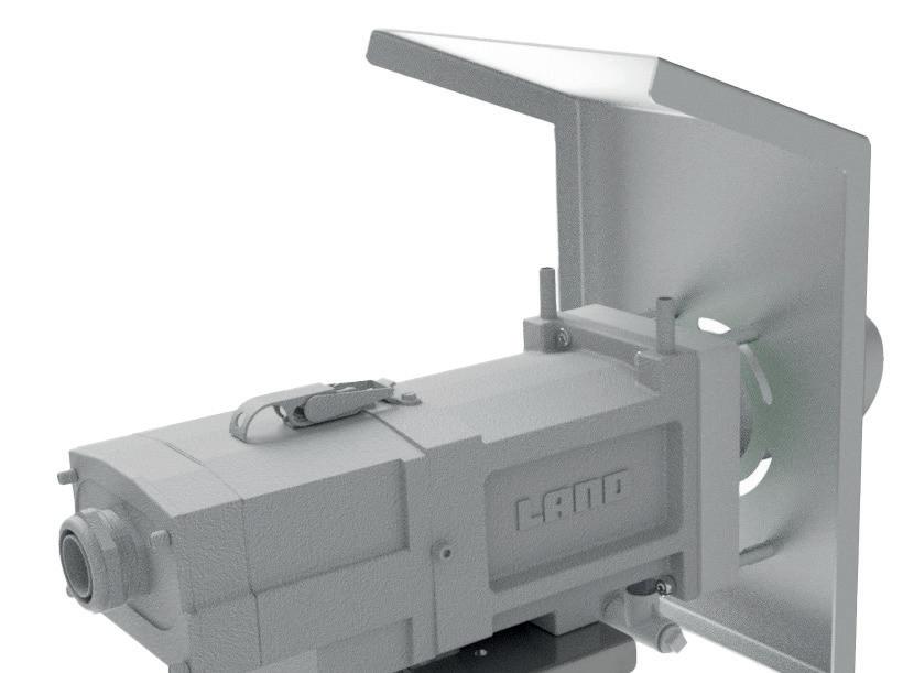
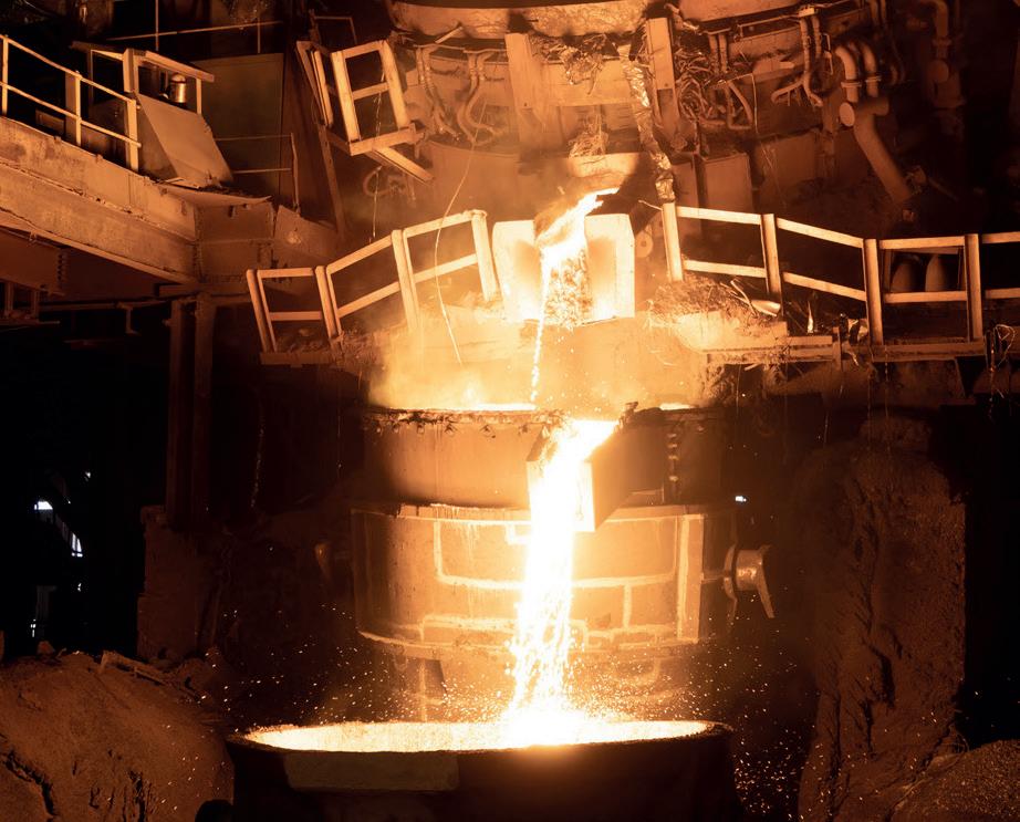
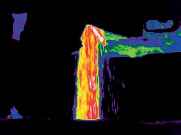
Perspectives: Emisshield From space to steel.
Pioneers of coke smelting, Pt.4 Abraham Darby 1st.


Matthew Moggridge Editor
matthewmoggridge@quartzltd.com
Last month I was highly critical of US President Donald Trump for his imposition of tariffs on UK steel. What do you expect, I’m British! I’ll be honest, I can’t see a time when I won’t be critical of Trump, I just don’t view him as a political statesman to be in any way admired or, indeed, believed. He’s an isolationist who thinks it’s his way or the highway and, to be honest, other nations should be giving it back to him with both barrels. If he wants a global trade war, let him have it, because there are no winners and that’s what he needs to learn. In fact, I’m rather hoping that King Charles uses some kind of flimsy excuse to postpone Trump’s state visit as I don’t see why we should be throwing down the red carpet for this man.
News this week that British Steel is consulting on the closure of its two Scunthorpe, UK-based blast furnaces, at the risk of losing 2,700 jobs, intensifies my dislike of President Trump, I’m not keen on having to put the word ‘president’ in front of his name.
One of the reasons given for British Steel’s highly probable demise is the imposition of tariffs – imposed by Trump – although there is a certain irony at play

inasmuch as British Steel is owned by Jingye Group, a Chinese company, and it is Chinese overcapacity that is putting a lot of pressure on steel companies globally. It is also at the root of Trump’s tariffs.
Trade unions have been highly critical of Jingye’s decision, but can you imagine losing £700,000 per day on top of everything else? Yes, it is devastating that almost 3,000 UK jobs could be lost as a result of the possible closure of the two blast furnaces, but what else is there?
UK Steel’s Gareth Stace has called the loss of Jingye’s blast furnace facilities ‘an irreparable break in the armour of national security’ – a comment similar to Trump’s reasoning behind the introduction of Section 232 tariffs the last time he was in power.
There’s never been a dull moment in the global steel industry and a common thread has always been Chinese overcapacity. I remember attending a conference somewhere in Europe when one speaker’s answer to virtually any question fired at him was ‘it’s all about China’. Now it’s also about decarbonization, digitalization and, of course, that crusty old chestnut, President Donald Trump and his tariffs.

Just as athletes rely on their teammates, we know that partnering with our customers brings the same level of support and dependability in the area of manufacturing productivity. Together, we can overcome challenges and achieve a shared goal, optimizing processes with regards to economic efficiency, safety, and environmental protection. Let’s improve together. Do you want to learn more? www.endress.com


India's ArcelorMittal Nippon Steel Limited (AMNS) has warned that it may have to drastically cut back its steel output in the country and delay capacity expansion plans owing to the Indian government's restrictions on imports of key steelmaking raw materials, government sources said on 6 March, citing internal communications. The checks have been imposed by the government over the last few months.
Source: Steel Orbis, 6 March 2025.

Indian steel manufacturer
ArcelorMittal's South African unit ArcelorMittal South Africa is seeking a 3.1 billion rand (US$167 million) rescue package to stop the closure of its steel mills in the country. The company is seeking funds from Industrial Development Corp, a national finance institution with a 6.4% stake in ArcelorMittal. The rescue package would prevent the complete shutdown of the company's long-steel Vereeniging and Newcastle facilities.
Source: Hindustan Times, 16 March 2025.

Whyalla Steelworks administrators have appointed BlueScope as a steelmaking advisor, the company announced. “This is a difficult time for the steel industry in the Asia Pacific region, but we are in a position to help. Accordingly, we will provide a team of experts from Port Kembla Steelworks to assist the administrators work through their process,” said Mark Vassella, managing director and chief executive officer of BlueScope.
Source: BlueScope, 6 March 2025.
DB Cargo UK and its sister company DB Cargo Polska are breathing new life into 60 BAA wagons for Tata Steel. The refurbished wagons, which will be capable of carrying steel slab and/or coil, are essential to support Tata Steel’s £1.25 billion transition in the UK from traditional iron and steel production to the use of cleaner and greener electric arc furnace technology. DB Polska is currently manufacturing new 40-foot wagon frames for the BAAs at its engineering facility
Bashundhara Multi Steel Industries (BMSIL), which has set a target to establish the world's largest single-strand minimill project for long steel products, is expected to commence operations by mid-next year, at the National Special Economic Zone in Mirsarai of Chattogram, according to company officials. BMSIL will be the first company in Bangladesh to produce rebar coil and wire rods. Furthermore, modern, environmentally friendly technology will be used in steel production, claims the company, reducing the cost per tonne of rod.
Source: TBS News, 12 March 2025.

Armenian prime minister Nikol Pashinyan attended the opening ceremony of the Armenian-American GTB Steel rebar plant located in Ararat, with $31 million invested
The San Diego-based Pacific Steel Group has selected Danieli & C. S.p.A. of Italy as the lead supplier of equipment for its new electric arc furnace (EAF) micromill. Danieli says the recycled-content EAF mill in Mojave, California, will make use of solar energy to produce up to 380kt /yr of steel rebar. The technology vendor says the contract it has been awarded by Pacific Steel involves supplying a continuous charge system through which recycled steel will be converted into new steel by Danieli Digimelter and LF digital melting and refining equipment.
Source: Construction and Demolition Recycling, 13 March 2025.
in the plant. The plant's production capacity is 112.8kt/ yr. It currently employs 240 people, but the number is planned to be increased to 500 within three years. Two 250-ton induction furnaces, a rolling mill, and a flow line for rebar production were purchased.
Source: ARKA News Agency, 17 March 2025.
in Rybnik, Poland, which are then being sent to the UK for final fitting, assembly and testing at DB Cargo UK’s
wagon maintenance facility in Stoke.
Source: Rail UK, 17 March 2025.
Toyota Tsusho, part of the Toyota Group, has announced that it is acquiring Radius Recycling, an industrial metals recycler based in Portland, Oregon. Radius, formerly known as Schnitzer Steel, operates more than 100 sites across 25 US states, Puerto Rico and parts of Western Canada. The purchase price for the deal is roughly $907 million, according to a release from Toyota Tsusho. The buyer expects to complete the deal in the third quarter of this year.
Source: Waste Dive, 17 March 2025.

Cleveland-Cliffs Inc. is laying off more than 600 workers at iron ore operations in Minnesota, according to reports. According to the Minneapolis Star Tribune, the action affects workers at Hibbing Taconite Co. and at its Minorca mine. “These temporary idles are necessary to rebalance working capital needs and consume excess pellet inventory produced in 2024,” the company said in a statement, according to
Japanese stainless steel producer Nippon Yakin Kogyo has successfully produced the first coil on its new HZMill at the Kawasaki plant, engineered and supplied by Primetals Technologies. Primetals Technologies said the HZ-Mill is its advanced split-housing 20-high mill featuring a large gap opening for easy strip threading and a double AS-U shape control system for stable rolling and improved productivity. It is the first ever HZ-Mill to be used for stainless steel production and has replaced two monoblock cold rolling mills.
Source: Primetals Technologies, 20 March 2025.
the newspaper. “We remain committed to supporting our employees and communities while monitoring market conditions.”
Source: Minneapolis Star Tribune, 21 March 2025.

International technology group ANDRITZ has received an order from ArcelorMittal Calvert to supply an annealing and coating line and a cold rolling mill for its new wholly owned, electrical steel production facility in Calvert, Alabama. The facility will be able to produce up to 150kt of non-grain oriented electrical steel per year, supporting the automotive and other industries’ journey toward more sustainable transportation and industrial/ commercial applications.
Source: Metal Center News, 21 March 2025.
Hyundai has revealed plans for a $5.8 billion investment in American manufacturing, announcing the construction of its first-ever steel mill in
Düsseldorf-based Hoberg & Driesch Röhrengruppe, one of Europe’s steel pipe distributors, has reached an agreement with Salzgitter Mannesmann Stahlhandel GmbH to acquire part of the latter’s pipe business in Germany. The agreement covers seamless heavy-wall pipes and precision steel pipes, according to a press release. The deal aims to allow Hoberg & Driesch to strengthen its market position and expand its product range.
Source: GMK Center, 21 March 2025
the United States. Located in Louisiana, the new facility will produce over 2.7 million metric tons of steel annually and create more than 1,400 American jobs. This major development is aimed at supplying steel directly to Hyundai's auto plants in Alabama and Georgia, projected to produce over one million American-made vehicles each year.
Source: Business Today, 25 March 2025.
Some Chinese steel mills have begun to cut production as the industry is pressured by oversupply and low profitability, Bloomberg has reported. According to a new release by consultancy Mysteel, four steelmakers in Xinjiang have announced a 10% cut in production since the beginning of this week. This news comes after the government announced in early March that it would restructure the steel industry by cutting production in the sector at the annual legislative meeting. Source: GMK Center, 25 March 2025.

While supporting domestic steel manufacturing, US President Donald Trump’s tariffs also risk fuelling inflation and making steel-consuming industries less competitive
PRESIDENT Donald Trump has gone on what some industry experts describe as a ‘tariff spree’– a reference to the perceived notion of using tariffs as a weapon aimed at stopping or restricting imports of not only steel but also a number of other products.
The 25% tariff imposition on all steel imports, purported to reduce dependency on imports and protect domestic steel producers from unfair foreign competition, has indeed helped stabilize and even raise prices for domestic steel.
The tariffs did benefit the domestic steel companies which, before that, were losing their foothold in a market inundated by cheap steel imports. US steel companies such as Nucor, Steel Dynamics, ClevelandCliffs, and US Steel, can benefit from higher domestic prices, reduced competition from foreign suppliers and a growing demand for US-produced steel.
While China, a leading steel supplier to the US, was exporting steel at prices much lower than the actual production costs – American experts alleged that this was because of the massive state subsidy given to its suppliers – its steel shipments had shown a downward trend after the 25% tariffs which were imposed first by Trump and retained by the Biden administration.
Tariffs also drive domestic steel companies to re-invest in expanding and modernizing their manufacturing
By Manik Mehta*
capabilities, besides restarting idled plants and also creating jobs. The US steel industry could well be on the verge of a new steel era.
The downside of tariffs
However, tariffs can produce retaliatory action from the trading nations hit by tariffs. Canada, for instance, announced 25% tariffs on more than $20 billion worth of US goods, including steel and aluminium. The European Union has also threatened tariffs on some $28 billion worth of US goods. Counter-tariffs will impact US export industries, including agriculture and automotive, thus almost nullifying the overall benefits for the US steel industry. US steel-consuming industries, relying on imported steel, will invariably pass down the higher import costs they have to bear, onto their customers and thereby fuel inflation.
This could possibly unleash a global trade war, thus affecting the smooth flow of trade, and resulting in slowing down economic growth.
President Trump, who had temporarily suspended the 25% steel tariffs under Section 232 against Canada, decided to re-impose them – and even threatened to double the tariffs on Canadian imports –after Ontario’s premier Doug Ford vowed to implement a 25% surcharge on electricity exports to the US.
*US correspondent, Steel Times International
According to data from the American Iron and Steel Institute (AISI), imports account for 23% of US finished steel consumption. Imports from Canada and Mexico – two US trade partners in the USMCA free-trade pact – accounted for some 8.6% of US consumption in 2024. Indeed, Canada is the largest steel exporter to the US, and a top supplier of hot-dipped galvanized sheet and cold-rolled sheet, representing 34% and 38% of the total US imports of these products respectively.
According to Kevin Dempsey, the AISI president/CEO, the AISI supports President Trump’s actions to implement tariffs on imported steel. “The comprehensive programme of national security tariffs and other measures on steel imports put in place in 2018 allowed the American steel industry to restart idled mills, rehire laid-off workers and begin investing tens of billions of dollars in new and upgraded plants. Unfortunately, the effectiveness of those measures has been eroded in recent years and foreign steel overproduction has led to increased dumping of excess foreign steel production onto world markets, as well as widespread transshipment and diversion of steel from third countries,” he said.
Dempsey added that the AISI ‘applauds’ the president’s actions to restore the
integrity of the tariffs on steel, and implement a robust and reinvigorated programme to address unfair trade practices. America must have a ‘sustainable, commercially viable steel industry to meet its national security needs’, he concluded.
Similar sentiments were voiced by the Steel Manufacturers Association (SMA), the largest US steel industry trade association, whose president Philip K. Bell, in a statement, described the tariffs as ‘another major step forward’ by President Trump to defend ‘our national, economic and energy security and create more American jobs’. He emphasized that the domestic steel industry had seen a revival after President Trump imposed tariffs on imported steel. But over time, the impact of those tariffs had lessened because of exemptions and exclusions that chipped away their effectiveness. ‘‘With a revised steel tariff, President Trump is boldly declaring that America is no longer a dumping ground for cheap, subsidized foreign steel’’, Bell summarised.
Bell said that by closing ‘loopholes in the tariff that have been exploited for years’,

President Trump would again ‘supercharge a steel industry that stands ready to rebuild America’. “Robust domestic steel production is essential for building new infrastructure that connects our country, building a fleet of ships capable of defending America’s interests around the world and building new manufacturing facilities that restore America’s manufacturing leadership.”
After the Biden administration’s negative reaction to the US Steel/Nippon Steel
merger, the Trump administration recently filed a motion to extend two deadlines in the US Steel and Nippon Steel’s lawsuit against a US national security panel to grant the government more time to make a conclusive decision on the merger; some experts interpreted this as the ‘clearest indication’ of President Trump’s inclination to allow the deal which had been blocked by President Biden.
President Trump said he would not object to Nippon Steel taking a minority stake in US Steel.
US Steel and Nippon Steel filed a lawsuit in January against the Committee on Foreign Investment in the US which examined foreign investments from a national security angle.
In their lawsuit against the CFIUS, US Steel and Nippon Steel said that President Biden was instrumental in prejudicing the committee’s decision, arguing that Biden’s rejection was aimed at getting support from the steelworkers union in Pennsylvania for his re-election bid. Nippon Steel said that it was going to make a change in the merger model after Trump’s comments. �


Weld breaks – and the related downtime – are the enemy of every finishing line. With the rising cost of raw materials and labor, downtime is getting more expensive. That is why steel producers are turning to advanced technology & machine automation o ered by Taylor-Winfield. Our coil joining welders are equipped with the most advanced features in the world, all of which work together to virtually eliminate weld breaks in the line. The question isn’t if you can a ord to upgrade or replace your coil joining welder, but if you can a ord not to.


This is the fourth and final part of the article highlighting Acesita’s journey, focusing on the years from 2010 onwards. By Germano Mendes de Paula*
THE year 2010 marked a significant rebound for the Brazilian economy, driven by a robust fiscal policy aimed at offsetting the effects of the global financial crisis. As a result, the country’s GDP grew by 7.5%, steel consumption surged by 40.5%, and demand for special flat steels increased by 52.9%. However, considering 2009 as a negative outlier, steel consumption in 2010 compared to 2008 showed a more modest rise of 8.5% overall and 12.7% for special flat steels. Unfortunately, this economic boom was not sustained, and Brazil’s economy proved to be highly volatile throughout the decade, leading some to refer to it as a ‘lost decade,’ similarly to what had happened in the 1980s.
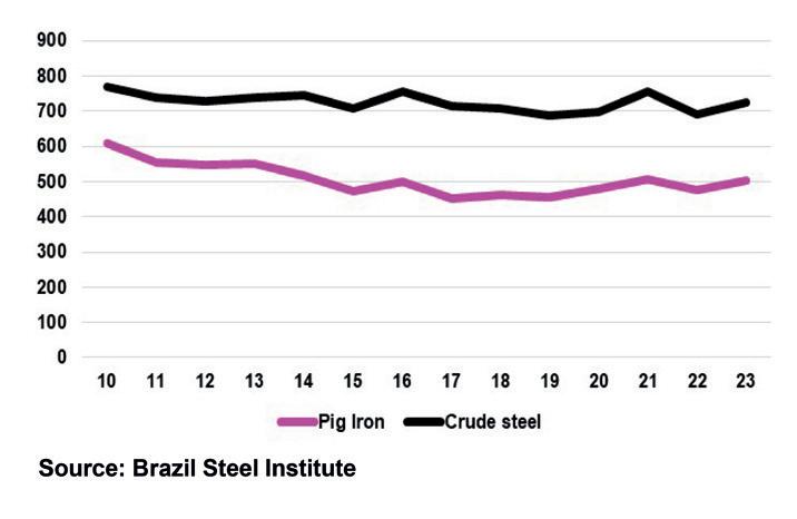
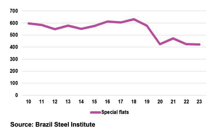
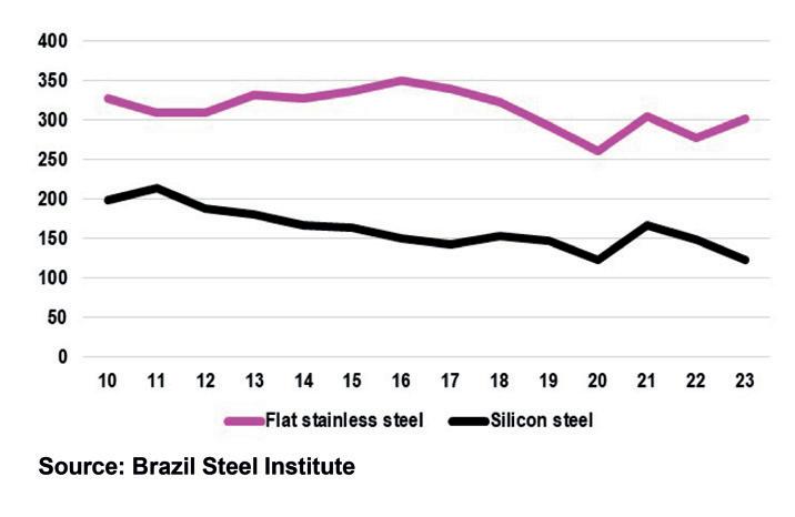
Given this context of economic instability, it is not surprising that the production output of the company, which rebranded as Aperam South America in 2011 following its spin-off from ArcelorMittal, did not experienced positive growth. Specifically, pig iron production fell from 609kt in 2010 to 454kt in 2019, while crude steel production decreased from 771kt to 688kt (Fig 1). Special flat steel production saw a slight decline from 598kt to 578kt (Fig 2). Concerning high-value products, flat stainless steel output dropped from 328kt to 292kt, while silicon steel production plummeted from 199kt to 147kt (Fig 3). Nonetheless, besides non-grain oriented electrical steels (NOES) and grain-oriented electrical steels (GOES), Aperam South America began producing High GrainOriented (HGO) steel – an advanced highpermeability product – starting in 2017, which enhances efficiency and reduces the size of electrical transformers. The development of HGO required significant
investments in modern equipment and supported dedicated R&D efforts (STI Digital, Feb 2024, p. 22).
In May 2022, Aperam South America announced a $117 million investment plan aimed primarily at modernising the Steckel mill. This initiative was intended to diversify the product range starting in 2024, introducing special steels with enhanced complexity and resilience, such as Endur, described as the world’s first highly corrosion-resistant stainless steel, launched by Aperam in 2019. The plan included improvements to the Steckel mill’s finishing operations, updates to the roughing mill and cooling system, and advancements in process control and automation.
The second priority of the investment package was focused on Aperam BioEnergia, to sustain the production of charcoal, seedlings, and seeds through advanced forestry technology. However, by December 2023, Aperam South America opted to suspend the investment plan due to increased imports from China, which also impacted other proposed and not yet approved projects, such as a new cold rolling mill set for 2024-2025. During the first half of 2023, imports of flat stainless and electrical steels rose by 17% year-onyear, leading the company to place its investments on hold.
Throughout this decade, pig iron production rose from 479kt in 2020 to 503kt in 2023 (the latest available information), while crude steel production figures were 696kt and 726kt, respectively (Fig 1). The latter figure is 5.8% below the peak observed in 2010. Special flat steel
production remained relatively stable, with a slight decrease from 424kt in 2020 to 423kt in 2023 (Graph 2), but reflecting a 33% decline compared to 2018. In terms of flat stainless steel, production numbers rose from 261kt in 2020 to 301kt in 2023, with a 14.2% drop from the maximum achieved in 2016. Silicon steel production remained stagnant, averaging around 140kt during the 2020-2023 period, but saw a decrease of 43% compared to 2011 levels (Fig 3).
In 2023, Aperam South America’s revenue distribution was as follows: 69% from stainless steel, 14% from carbon steels, 10% from GOES, and 8% from NOES. The market segments for stainless steel were led by general industry (24%), followed by energy and chemicals (23%), catering and appliances (21%), automotive (19%), building and construction (9%), and transport (4%).
Notably, the Brazilian subsidiary accounted for 40% of crude steel production and 37% of total shipments in the stainless and electrical steel segment in 2023, employing 4,651 workers, which constituted 40.5% of the group’s total workforce.
It is essential to note that since 2011, Aperam South America has utilized only charcoal in its blast furnaces. To provide raw materials for charcoal production, the company manages 150k hectares of eucalyptus forest reserves, including over 60k hectares of natural vegetation preserves and wildlife corridors. There are plans to expand this forestry area by 24% by 2030 compared to 2022 levels, with an anticipated annual planting area 18%
* Professor in Economics, Federal University of Uberlândia, Brazil. E-mail: germano@ufu.br
Steel manufacturing that’s both decarbonized and profitable? Transform your operations through unified electrification, automation, and digitalization solutions and meet your goals.
Be an #ImpactMaker. Learn more.
se.com/metals
larger in the period 2023-2030 than that established between 2015 and 2022.
In May 2022, Aperam South America proclaimed itself the world’s first carbonneutral company in the special flat steel sector, based on scope 1 and 2 emissions. Assessments demonstrated that the integrated operations of Aperam South America and Aperam BioEnergia resulted in the removal of more greenhouse gases from the atmosphere than were emitted throughout the steel and charcoal production processes during the 20202021 period. After neutralising its total greenhouse gas emissions, the company
managed to remove an additional 33kt of carbon emissions from the atmosphere.
In March 2025, International Finance Corporation (IFC), a member of the World Bank Group, announced a €250 million financing package to Aperam BioEnergia. The investment will support the acquisition of complementary eucalyptus plantations and the modernisation of Aperam South America’s charcoal-producing kilns with cleaner and more efficient technology, further enhancing the sustainability of Aperam BioEnergia’s operations.
As Acesita/Aperam South America celebrated its 80th anniversary in
2024, it stood out as a resilient player, having navigated numerous periods of macroeconomic instability while significantly transforming its production structure. Today, it is recognised as a strategic asset within the Aperam group, crucial for their decarbonization initiatives, particularly with its unique charcoalintegrated mill technological route, which is exclusively used in Brazil.
This innovative approach not only enhances operational sustainability but also underlines the company’s commitment to addressing environmental challenges in the steel sector. �


%
%
< 1 min
Schedule generation time

Comprehensive supply chain planning solution. Raw materials supply, production planning, what-if scenarios.


Most advanced scheduling software. Automated generation of casting and rolling programs. Expert filtering, editing, scripting. Covers all constraints, KPIs

Centralized planning system for slot-based production. Covers diverse steel grades, profiles, cutting optimization.

Automatic reallocation of slabs, coils. Ranks according to grade, geometry, processing steps. Maximizes revenue.


THE import duty, announced by Trump, has enabled Chinese and South Korean steel producers to capture a larger share of the Indian steel market, the fastest-growing consumer market in the world.
With an estimated export volume of less than 100kt/yr , valued at $3 billion, India remains a minor player in the US steel industry compared to Canada and Brazil, which together account for approximately 30% of US steel imports. Consequently, President Trump’s tariff imposition is unlikely to have a significant direct impact on the Indian steel industry.
India’s steel secretary, Sandeep Poundrik, commented, “The US import tariff on global steel will not have much impact on Indian metal companies, as a 15% duty already existed well before the recent announcement. However, this duty was partially waived through certain agreements and bilateral business partnerships. The recent tariff imposition is merely a change in approach, so it is not new for Indian steelmakers.”
Indirect impact
However, the US tariff levy is expected to weaken the pricing power of Indian steel mills, directly impacting their sales and revenue due to global oversupply, lack of competitiveness, and the re-direction of global shipments toward India. When the US implemented a similar tariff during President Trump’s previous term, which ended four years ago, it triggered a wave of protectionist measures from countries worldwide, and India was not immune to it.


The 25% import duty imposed by the Trump administration in the United States has opened the floodgates for global steel producers, especially from China and South Korea, to dump their output into Indian markets at prices lower than the cost of production for Indian steelmakers. By Dilip Kumar Jha*
Source: Joint Plant Committee, *April-December period
Source: Joint Plant Committee under Ministry of Steel; * India Bureau of Mines
For example, the European Union faced a surge in re-directed Chinese steel exports from the United States and responded by imposing its own restrictions. This had a direct negative impact on India’s steel exports to Europe as those markets tightened. Meanwhile, China, with limited options to offload its steel elsewhere, turned its focus to India, leading to an increase in steel imports from the Chinese market. This shift resulted in a higher volume of steel flooding into Indian markets, putting significant pressure on domestic steelmakers.
Hui Ting Sim, assistant vice president at Moody’s Ratings, stated, “The US tariffs on steel will increase competition and exacerbate oversupply in other steelproducing markets. Indian steel producers
will face heightened challenges in exporting their products. Over the past year, high steel imports into India have already dampened prices and earnings for Indian steel producers.”
Imports up, exports down
According to the Joint Plant Committee (JPC) under the Union Ministry of Steel, India’s imports of finished steel have registered a significant increase in recent months. In December 2024 alone, finished steel imports rose to 0.761Mt, up from 0.745Mt in the preceding month. However, this represents a 15.7% decline from the 0.903Mt recorded in December 2023. For the April–December 2024 period, India’s finished steel imports increased by 20.3% to 7.27Mt , compared to 6.049Mt reported

during the same period last year.
On the other hand, India’s finished steel exports climbed by 11.5% to 0.446Mt in December 2024, up from 0.400Mt in the previous month. However, this reflects a 30.8% decline from the 0.644 Mt recorded in December 2023. For the April–December 2024 period, cumulative export volumes dropped by 24.6% to 3.6Mt, compared to 4.773Mt reported during the same period last year.
Protectionism
While India is not a major steel exporter to the US, previous tariffs led to protectionist measures that negatively impacted Indian exports, particularly to the European Union. India’s steel imports from China jumped to approximately 1.75Mt during AprilDecember 2024, compared to around 1.2Mt recorded during the corresponding period last year. The government is considering safeguard duties to protect local producers as global trade dynamics shift in response to Trump’s policies.
Leading credit rating agency India Ratings and Research anticipates domestic steel
demand to grow by 9–11% year-on-year in the fiscal year 2024–25. This demand growth is likely to be supported by the government’s continued investment in infrastructure projects, such as roads, railways, and ports, along with stable growth in end-user industries. However, the
imposition of duties and tariffs by various countries on steel imports poses a persistent threat of high import volumes into India, where demand growth remains relatively strong. This could lead to a reorganization


of supply chains and keep domestic steel prices in check.
Meanwhile, India’s Directorate General of Trade Remedies (DGTR) has initiated anti-dumping investigations based on a substantiated application filed by the domestic industry, alleging that the dumping of goods into the country is causing injury to local producers. To address concerns about increased steel dumping from other countries, Anti-Dumping Duty (ADD) measures are already in place for certain steel products.
These include seamless tubes, pipes, and hollow profiles of iron, alloy, or non-alloy steel (excluding cast iron and stainless steel) from China; electro-galvanized steel from Korea, Japan, and Singapore; stainless-steel seamless tubes and pipes from China; and welded stainless steel pipes and tubes from Vietnam and Thailand.
Rising steel imports, coupled with Trump’s 25% tariff, could pose additional challenges for Indian steelmakers, even as domestic demand for steel remains high. �
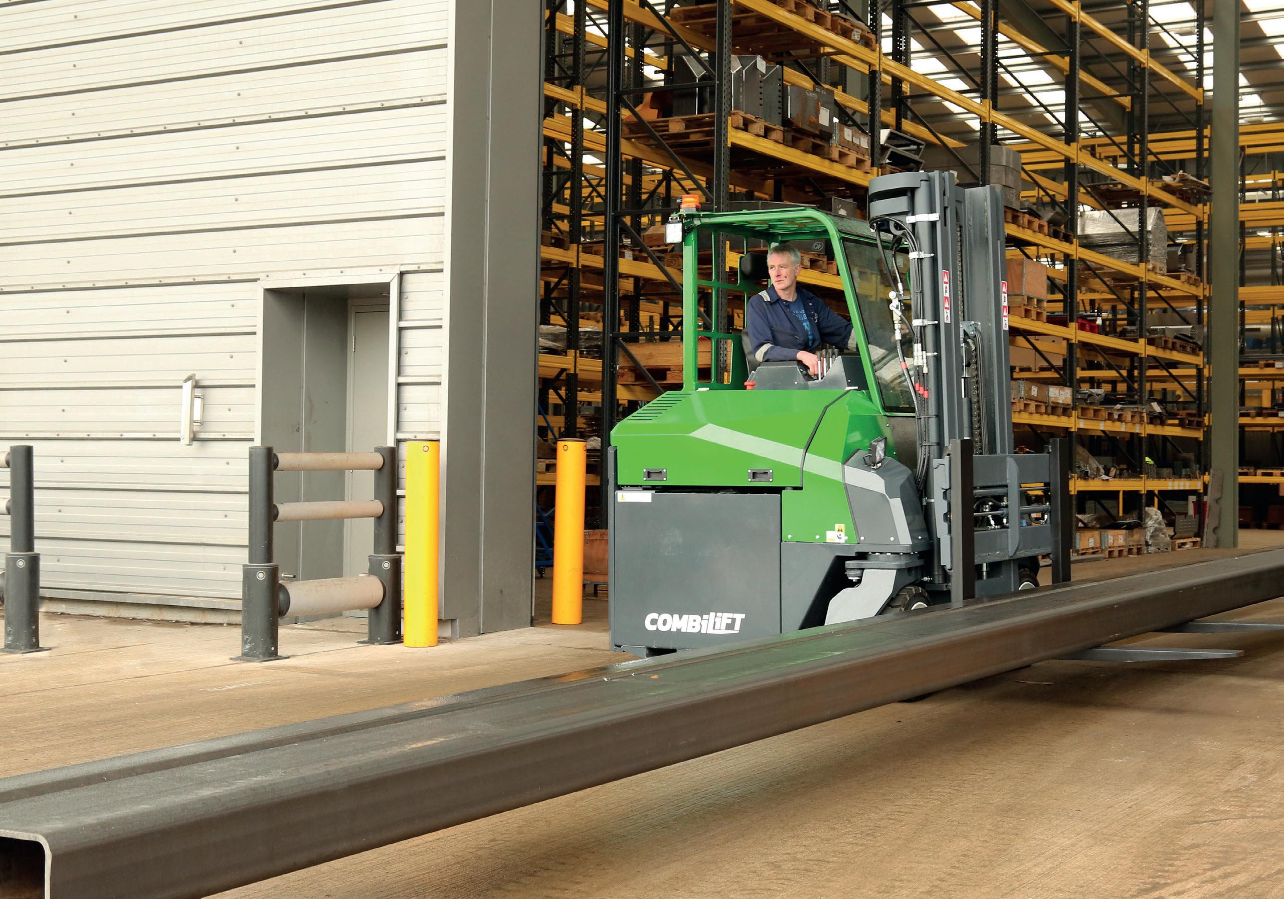
Combilift’s range of multidirectional forklifts, pedestrian reach trucks, straddle carriers and container loaders will allow you to maximize the capacity, improve efficiency and enhance the safety of your facility.
Contact Us Today
To find out how Combilift can help you unlock every inch of your storage space.


It might seem like only a few weeks since the AISTech conference and exposition took place in Columbus, Ohio, but it’s a year on and this year’s event in Nashville, TN takes place 5-8 May at the Music City Centre. Here’s just a little taster of what some of the exhibitors will be showing. This is a great event and should not be missed by any self-respecting steel industry professional.
The AUMUND Group, supplier of solutions for conveying and storing bulk materials, will be presenting its Bucket Apron Conveyors for transporting hot DRI, which is to be supplied by AUMUND Fördertechnik for the ThyssenKrupp Steel direct reduction plant at Duisburg in Germany. In the hydrogen-based production process the two Hot Material Conveyors will be the connecting point between the direct reduction plant and the smelting furnace.
Both conveyors will be installed beneath the shaft furnace of the direct reduction plant, and their function is to feed the smelting furnace directly with hot DRI. The direct reduction shaft furnace designed by Midrex Technologies, USA, is the core technology of the plant. “The order for ThyssenKrupp Steel is not only a very significant project for us, but will play a leading role in the transformation of green steel in Germany,” said Alberto Lalia, head of the metallurgy business unit at AUMUND
Fördertechnik. He added: “Thanks to a large extent to the success of our joint projects with MIDREX, we are very proud of our proven experience in conveying technology for direct reduction plants.”
The patented AUMUND Hot Material Conveyors are a closed system for continuous material feed. They transport the DRI in an inert atmosphere which prevents it coming into contact with the air, so that avoidance of re-oxidation is assured.
One of the advantages of this mechanical enclosed system is its significantly lower energy consumption in comparison with pneumatic conveying concepts. Unlike with pneumatic conveying, on a mechanical conveyor there is no relative movement between the equipment and the transported material on the conveying route. This prevents any additional fines being generated during transportation.
The AUMUND equipment is automated, with sensors monitoring the temperature and the condition of the material on the conveyor. The concept of the transport system is that inert gas protects the conveyed material from contact with outside air, and dust remains inside the system.
AUMUND will be exhibiting at booth #1056.

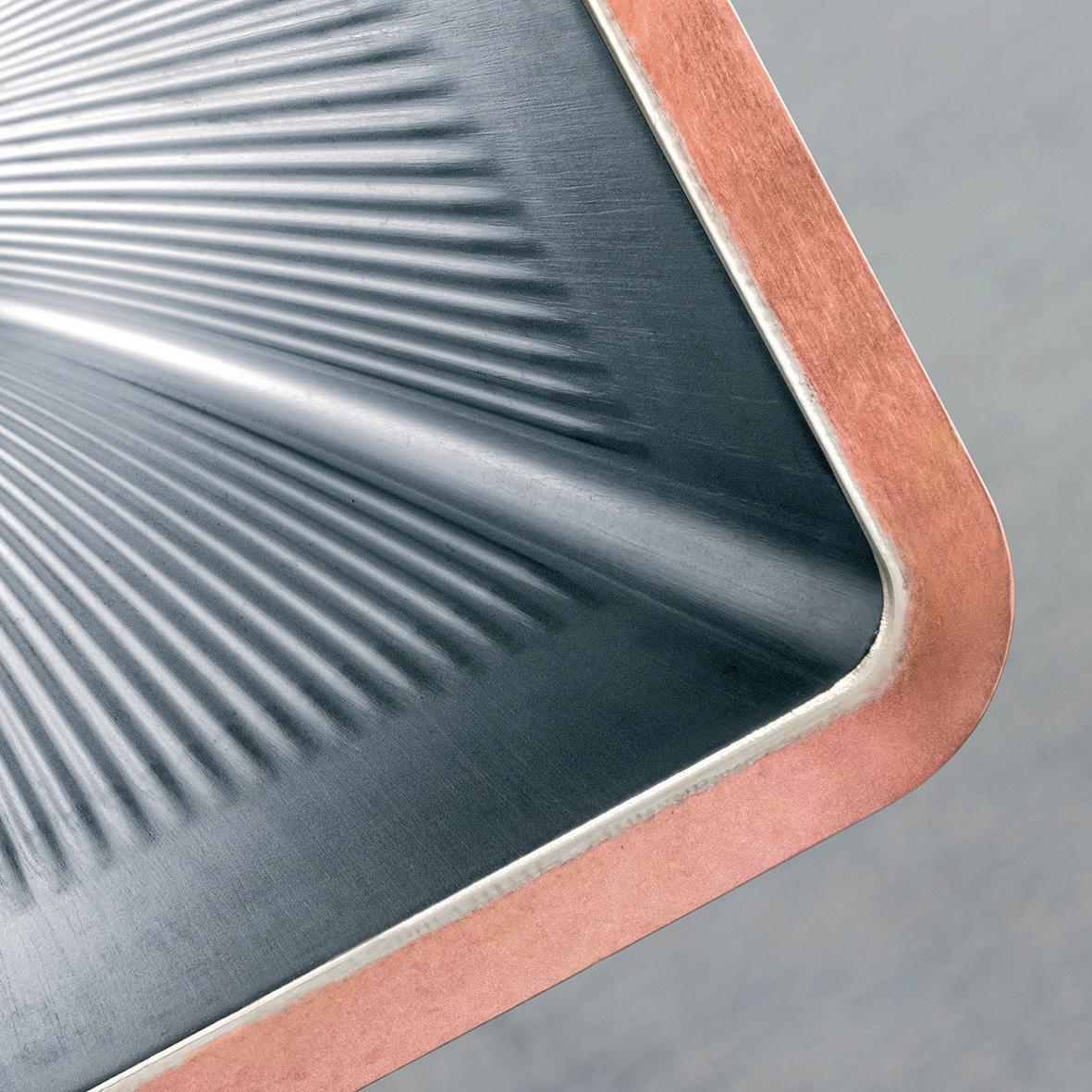
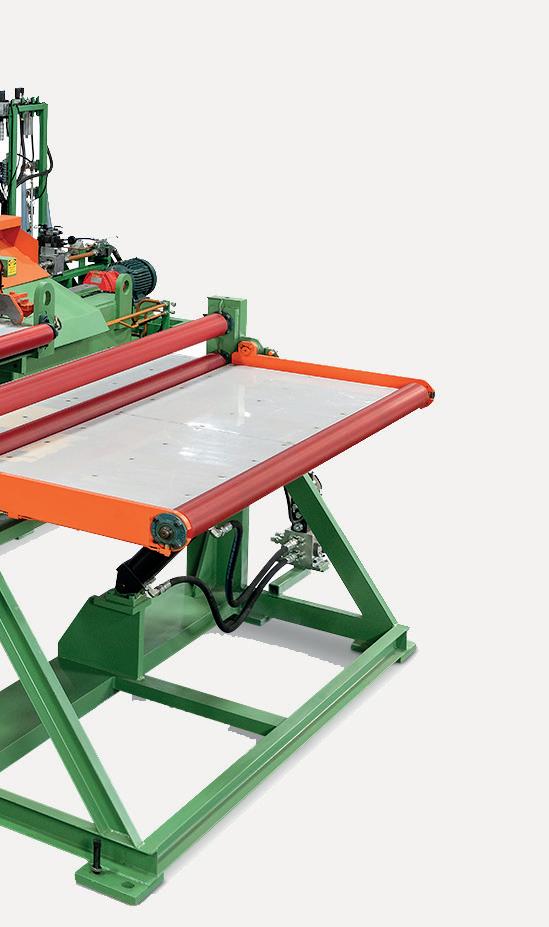
cunova, a provider of products and solutions made from copper and copper alloys, will be showcasing the WAVE® Mould Tube, which has specifically been designed for continuous billet casting. This technology aims to address issues, such as poor billet quality (rhomboidity, cracks, snaking) or low lifetime. With its unique design, the WAVE® Mould Tube improves both the shape and quality of the billet, while simultaneously extending the lifetime of the mould, says cunova.
The WAVE® Mould Tube features a special geometry, where a series of wave patterns are applied to the hot face of the mould. These waves create a mirrored pattern on the billet surface as it begins to solidify. The mould wall and the billet surface interlock and guide the shell through the length of the mould, ensuring more uniform heat extraction and, consequently, more uniform shell formation. This results in improved billet shaping and a more stable billet structure during the critical solidification process, claims cunova.
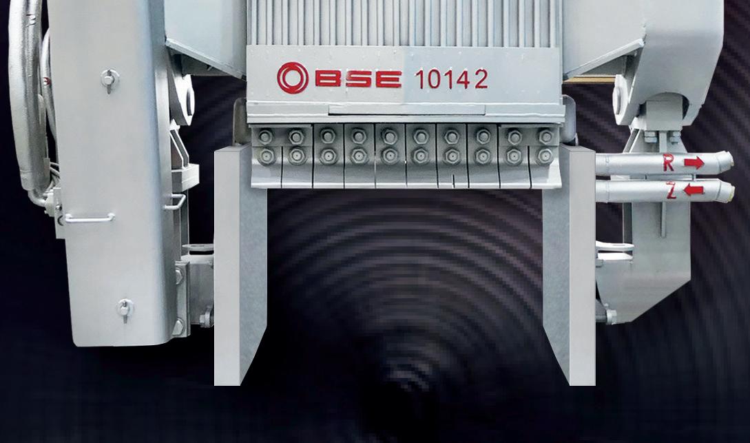
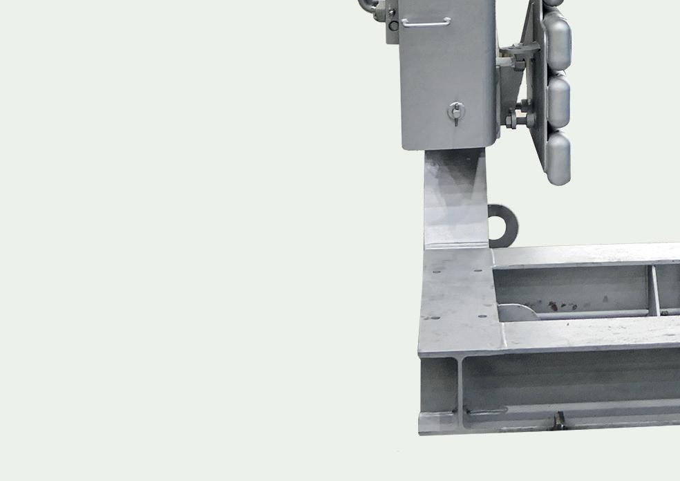
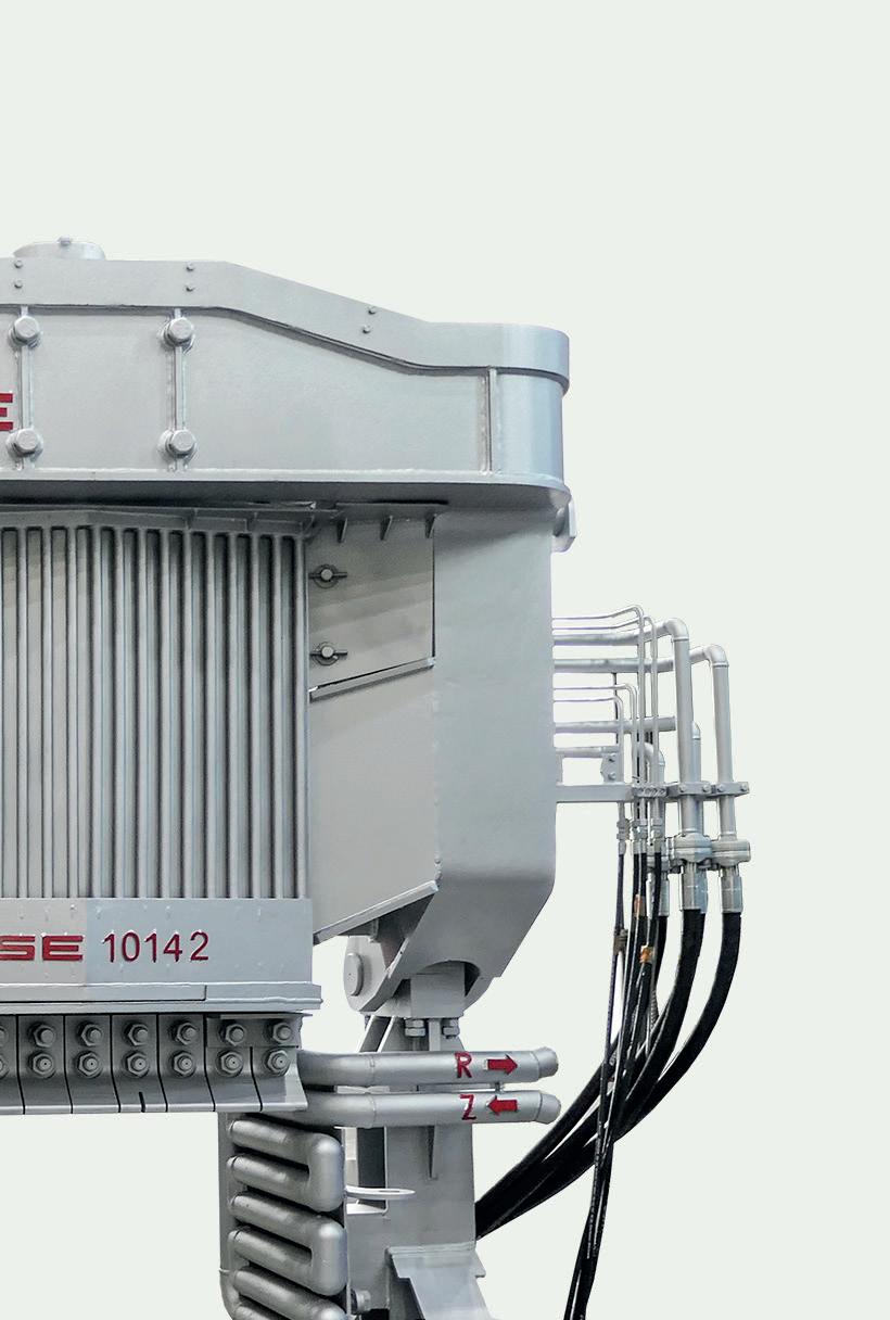
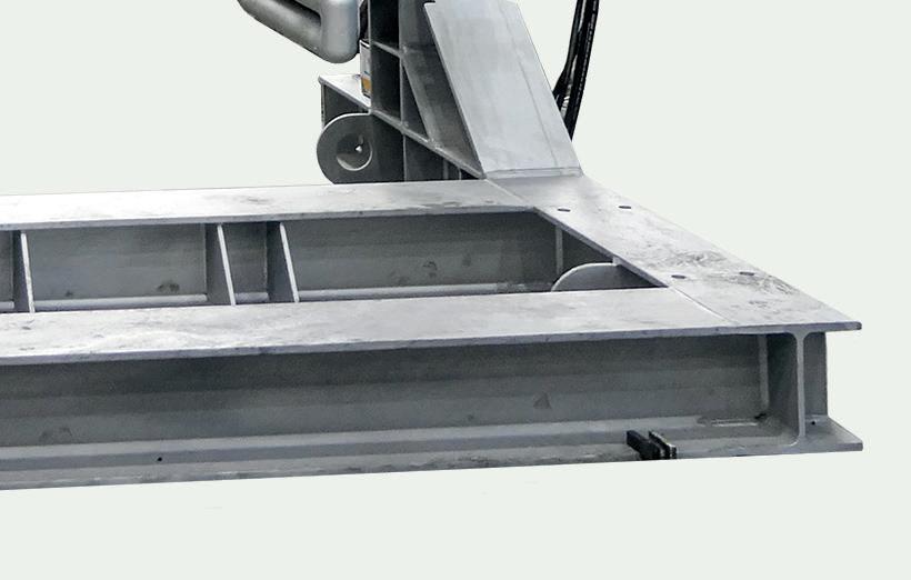
BSE, a sister company of Badische Stahlwerke GmbH (BSW), an electric arc furnace steel plant, provides services that aim to increase the safety, efficiency and productivity in the electric steel industry worldwide. Exhibiting at this year’s AISTech, BSE will be highlighting its BSE DoorMan®, the latest addition to the company’s Safe Steel product family, designed to optimize slag management and eliminate manual furnace door cleaning.
The DoorMan® is the newest innovation in BSE’s comprehensive safety and automation line-up, which includes EBT SandMan®, Ladle SandMan®, and Tap Hole Manipulator (THM). The DoorMan® is a new furnace door concept with an automatic slag cleaning function,
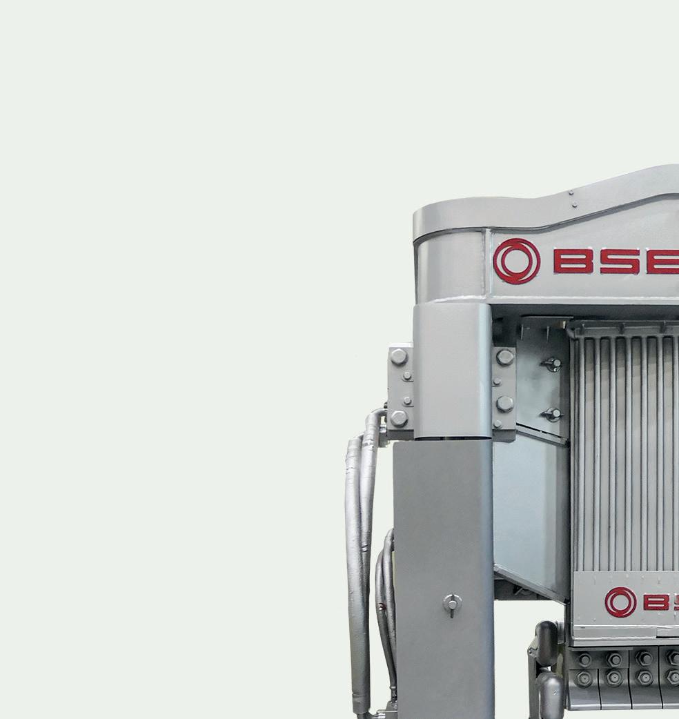
designed to ensure a safe, standardized process while minimizing human intervention. It is fully compatible with existing EAF set-ups, requiring no major modifications to the upper shell, lower shell, or furnace platform.
With increasing automation, stricter safety regulations, and labour shortages affecting steelmakers, the DoorMan® provides a cost-effective, future-ready solution for boosting productivity while enhancing workplace safety, says BSE.
BSE will be exhibiting at booth #1506.
The WAVE® Mould Tube is compatible with various mould coatings and can be used with all standard copper alloys. It is available for both round and rectangular moulds and is suitable for a wide range of applications, including casting medium-carbon steels.
cunova will be exhibiting at booth #2545.


Dassault Systèmes, a provider of collaborative 3D virtual environments to imagine sustainable innovations, will be exhibiting its product, DELMIA, which delivers solutions for metals manufacturing.
DELMIA’s solution for metals manufacturers leverages Industry 4.0 technologies like IoT, AI, and data analytics to enhance real-time monitoring, predictive maintenance, and operational efficiency. Its tools, including manufacturing operations management, advanced scheduling, and sales and operations planning, streamline processes, reduce waste, and enable precise demandsupply alignment, says the company.
The solutions also support sustainability initiatives by integrating virtual twins and green practices to lower the carbon footprint and foster a circular economy. By adopting DELMIA, metals manufacturers can gain a competitive edge, improve efficiency, and align with global sustainability goals.
Dassault Systèmes will be exhibiting
at booth #951.


Linde, a global industrial gases and engineering company, has developed the Three-in-One Injector to be used as an oxygen lance, a carbon injector and an oxyfuel burner. This injector has the capability to replace existing fixed-wall oxygen injectors, entraining carbon into the primary oxygen stream and then accelerating it to supersonic velocities, generating a coherent jet of fluidized carbon in oxygen that is able to traverse the distance from the wall of the furnace to the bath/slag interface.
The injector can accomplish supersonic carbon injection without the need to modify the existing infrastructure. Delivering the carbon
at high momentum, has the advantages of increasing carbon utilization, reducing power consumption by increasing chemical energy input into the bath, reducing electrode consumption and allowing the use of lighter carbon material, (e.g. petcoke, biocarbon, and lower cost coals) says Linde.
The Linde Three-in-One Injector is designed for the harsh EAF environment, featuring key design elements that enable it to function for extended periods with limited wear or maintenance issues. This includes a modular design that allows the inner carbon conveying assembly to be replaced in-situ, meaning that the inner nozzle can be replaced in between heats


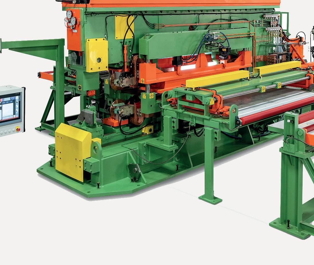
Guild International offers a complete line of coil joining and end welding
machines for almost any steel processing, tube producing or stamping application. At AISTech, the company will be highlighting its Guild QM Quicklap Seam Welder, a product that is ideally suited to join coils for various flat metal processing
without having to remove the whole injector. The injector also works with existing oxygen, natural gas and carbon conveying systems and does not require any additional compressed air lines, pressure, skid upgrade, controls, or equipment.
Linde will be exhibiting at booth #2936.
lines by resistance welding two slightly overlapped strip ends. The weld created by the QM series seam welder is an overlapped resistance weld that is generally as strong as the parent material. Any weldable material can be joined on these machines. The two coil ends are slightly overlapped, and the upper and lower weld wheels roll across the overlapped ends while passing current through the material to forge the weld. Hardened planish rolls,
one upper and one lower, follow the weld wheels, and the result is a fast, flat, and strong weld. An optional induction annealer can also be included on the QM to post-anneal the weld during the same pass as welding and planishing. The QMT and QMM can shear, weld, and planish material ranging from about 0.1mm (0.004“) up to about 3.5mm (0.137“) thick, and as wide as necessary, all in under a minute. Recent machines have been used for strip up to 1900mm (76“) wide.
Guild International will be exhibiting at booth #1361.
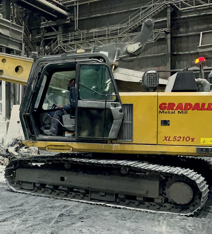
Gradall Industries, a supplier of equipment for infrastructure maintenance, agriculture and other applications, will be showcasing its XL Series V featuring an innovative boom design, which the company claims provides exceptional reach and movement. With a continuous 360-degree boom tilt, the machines can work in hard-to-reach places, telescoping into position with minimal overhead clearance. Attachments – hammers, rippers, buckets and drills – can be precisely directed to the job at hand, whether desculling and cleaning hot metal ladles, removing bricks, cleaning distribution channels, or placing tap
holes. Heavy-duty boom rollers reinforce optimum strength for the exceptionally rugged boom, and the boom tilt motor is at the rear of the cradle protecting it from damage.
Gradall industrial maintenance machines feature cabs designed for operator comfort and safety, with plenty of windows for excellent visibility in all directions. Gradall, Deere or SAE boom control joysticks are built into the adjustable seat, and foot pedals allow the operator exacting control to position the carrier. For operator comfort, heaters, air conditioning and more are all standard.
Gradall will be exhibiting at booth #2013.
Take the next step towards transparent calculation and tracking of your emissions at piece and product level.
PRODUCT CARBON FOOTPRINT TRACKING:
PRODUCT ID: CL CAL 1434


NIPPON Steel is set to pay $979 per ton of US Steel’s crude steel production – a price about 1.4 to 1.5 times higher than the market capitalisation per ton for both US Steel ($689) and Nippon Steel ($638) as of the end of FY2023, suggesting a substantial M&A premium. By contrast, market capitalisations per ton for comparable USbased electric arc furnace (EAF) companies are significantly higher, with Nucor Corporation $2,018 and Steel Dynamics at $1,852 at the end of FY20231,2. While Nippon Steel’s willingness to pay such a premium demonstrates its high expectations for US Steel, which operates using BFs, the market currently places a much higher valuation on EAF companies. This raises a critical question: could US Steel’s reliance on BFs make it a less attractive investment when stacked against EAF-based competitors? This commentary explores the missed opportunities and potential strategic gaps in Nippon Steel’s approach.
The two EAF operators, Nucor and Steel Dynamics, have better margins and over the past five years, they have consistently achieved superior EBITDA levels. In 2023, US Steel’s EBITDA per ton was $124, compared to $295 for Nucor and $195 for Steel Dynamics – both more than 1.5 times higher than US Steel’s figure3,4,5. In other words, these EAF mills are maintaining higher profitability than a blast furnacebased competitor. Fig 1
One key factor driving these margins is the flexible cost structure of EAF mills, characterised by a smaller share of fixed costs. This allows them to quickly adjust production to meet demand and maintain more stable margins over time – unlike BFs, which must operate continuously for prolonged periods6,7,8. This highlights the potential profitability advantage of EAF producers over traditional BF-BOF producers like US Steel – also implying that BF-BOF producers face greater sensitivity to price
fluctuations.
In particular, we feel that the medium-tolong-term risk of carbon pricing and other decarbonization measures in the mediumto-long-term is likely to significantly impact US Steel’s BF-BOF steel production. The company – with already low industry margins – faces greater sensitivity to commodity price fluctuations, an additional financial headwind would be unwelcome to its new owners.
The high market caps of US Steel’s domestic competitors likely rules out an M&A strategy for American EAF mills, but perhaps M&A is a strategy that doesn’t need to be pursued where there is greenfield opportunity in the country9. It is true that the US market is to some extent saturated, however there is still demand and opportunity to produce steel with fair margins. Building EAF-based steel mills could navigate the challenges associated with US Steel’s BF-BOF technology, *ESG research fellow, Transition Asia
remaining flexible, resilient and able to produce the low-carbon products demanded by customers.
Nippon Steel has already partnered with ArcelorMittal to build a new EAF in Calvert, Alabama. For Nippon Steel, greenfield investments in the US are not unfamiliar territory. EAFs are the most costeffective investment to decarbonize steel production and the average investment per ton for newly constructed or planned EAFs in the US in recent years stands at $676, a significant discount to the US Steel acquisition price10,11,12
Should Nippon Steel seek to pursue a strategy based on primary iron production there is the opportunity to build H2-DRI facilities. Admittedly, these facilities will cost substantial amounts. The total investment that Swedish start-up Stegra, formerly known as H2 Green Steel, has allocated for their H2-DRI-EAF green steel plant is approximately $6 billion. However, through the Industrial Demonstrations Programme, funded by the Bipartisan Infrastructure Law and the Inflation Reduction Act, up to $500 million in funding can be secured for the construction of H2-DRI-EAF facilities in the
US, helping to mitigate initial investment risks13. Attractive tax relief is also available to green hydrogen producers, further derisking green investments.
Production from green steel projects can additionally be hedged through take or pay contracts as seen in the Swedish green steel projects.
Nippon Steel has already publicly expressed its intentions to make largescale investments in US Steel post-2027,
company, disruptive to the market and attractive to shareholders.
With President-elect Trump already signalling that the US Steel deal will be blocked and premiums for pure-play EAF mills seemingly too high, Nippon Steel should remain open to greenfield investments within the US.
Investing in EAF steel processes rather than maintaining and re-investing into BFBOF technology would not only contribute
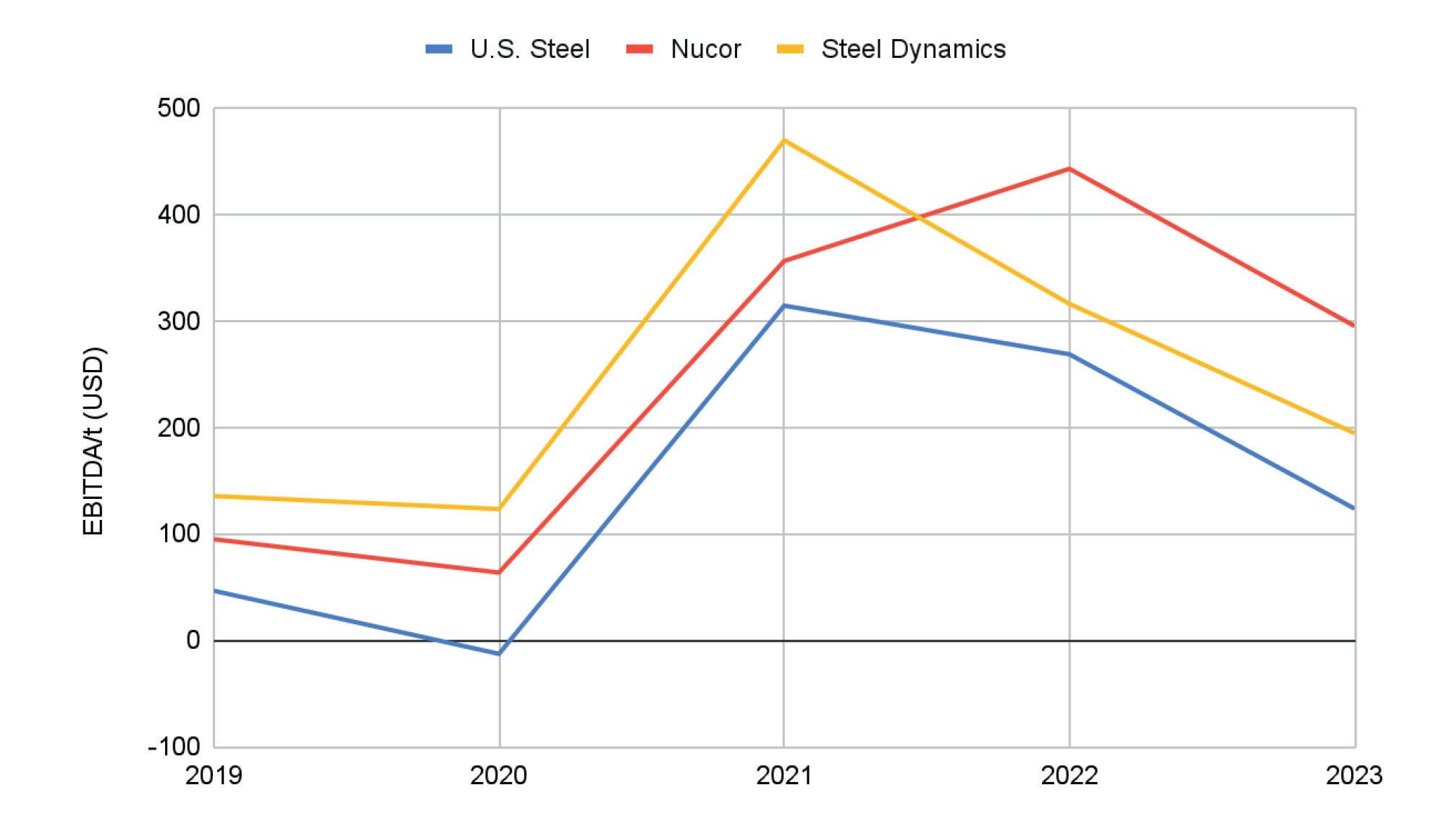
Source: Annual Reports, TA analysis
and given that the last BF relining at the Edgar Thomson Plant took place in 2001, there are indications that large CAPEX investments will be required soon14 Instead of investing heavily in renewing US Steel’s ageing plants, the construction of greenfield H2-DRI-EAF or EAF facilities in the US could prove beneficial for the
1. https://worldsteel.org/data/top-producers/
2. https://companiesmarketcap.com/
3. https://d1io3yog0oux5.cloudfront.
4. https://www.fitchratings.com/research/corporatefinance/fitch-affirms-nucor-idr-at-a-outlookstable-26-02-2024
5. https://www.forbes.com/sites/ greatspeculations/2023/10/17/nucor-steel-titan-rising/
6. https://rtpatterson.com/revitalizing-the-steel-industrythe-transformative-role-of-electric-arc-furnaces-insustainable-steelmaking/?form=MG0AV3
7. If Nucor and Steel Dynamics were each acquired at the same percentage premium as U.S. Steel, their acquisition costs would be $60.8 billion for Nucor and $27.2 billion for Steel Dynamics. Nucor’s cost would be about 3.9 times that of acquiring U.S. Steel, while Steel Dynamics, despite producing only 65% as much crude steel as U.S. Steel, would still cost 1.7 times more.
to reducing corporate emissions but also support the company in strengthening its presence in the strategically important US market. Through maintaining exposure to BF-BOF technologies and the challenges they attract, Nippon Steel risks missing a critical opportunity to invest in the rapidly expanding green steel market. �
net/_871a703ad34e43f8f0477a06ba2d66bd/ussteel/ db/3222/30221/segment_and_financial_operational_ data/U.+S.+Steel+-+Segment+and+Financial+Operat ional+Data+-+Q4+2023+20240201.pdf
8. https://icrm.indigotools.com/IR/ IAC/?Ticker=NUE&Exchange=NYSE#
9. https://ir.steeldynamics.com/annual-reports/
10. https://www.nipponsteel.com/en/ news/20201222_100.html
11. https://buildsteel.org/news/steel-dynamics-sintontexas/
12. https://www.recyclingtoday.com/news/big-river-steelexpansion-arkansas-ferrous-scrap/
13. https://www.energy.gov/oced/industrialdemonstrations-program-selections-award-negotiationsiron-and-steel
14. https://rmi.org/wp-content/uploads/dlm_ uploads/2024/02/PA_steel_memo.pdf


How China’s blast furnace overcapacity erodes profitability and impedes the green steel transition.
By Xinyi Shen*
CHINA’S steel industry, the largest in the world, plays a pivotal role in the country’s carbon emissions. Responsible for around 17% of China’s total emissions, the sector is a critical focus in the country’s pursuit of carbon neutrality by 2060. However, the industry’s reliance on coal-based blast furnaces (BF) and its overcapacity present significant challenges. Despite the government’s ambitious decarbonisation goals, including increasing the share of electric arc furnace (EAF) steelmaking, the industry struggles to transition due to continued overcapacity and weak profitability.
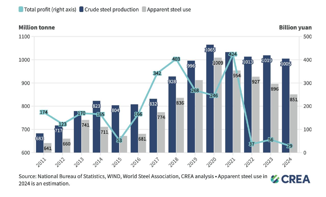
In 2024, China’s crude steel production surpassed 1 billion tonnes for the fifth consecutive year, underscoring the sector’s dominance. However, consumption has stagnated, exacerbating the oversupply problem. This article explores the challenges facing China’s steel sector, the path to decarbonization, and the urgent reforms needed to align the industry with China’s climate targets.
China’s steel production reached 1 billion tonnes in 2024, maintaining its position as the global leader in steel output (Fig 1). However, production declined by 5.6%
compared to the record high in 2020, while consumption plummeted by 15.6% over the past four years. The downturn in key industries such as real estate, traditionally a major consumer of steel, has further dampened domestic demand.
As a result, overcapacity has become a pervasive issue. While China continues to produce large quantities of steel, excess supply has led to near-zero profit margins for producers. In 2024, profits for the entire steel sector fell to an historic low of 29 billion yuan, marking the third consecutive year of declining profitability. The situation is unsustainable and demands urgent policy interventions to address overproduction and accelerate the industry’s transition to lowcarbon technologies.
The green steel challenge
China’s carbon neutrality ambitions hinge on transforming its steel industry, which relies heavily on the carbon-intensive BFBOF process. This method, which uses iron ore and coke, produces substantial CO2 emissions. The steel industry must shift towards more sustainable practices to align with the country’s climate goals. Electric arc furnaces (EAF), which utilise scrap steel and are significantly less carbon-intensive, offer a promising solution. However, EAF
*Researcher, Centre for Research on Energy and Clean Air
adoption has been slow due to limited scrap supply and economic barriers.
EAF accounts for just 10% of China’s crude steel production, far below the government’s 15% target for 2025. Despite the urgency of decarbonization, progress in increasing the EAF share has stagnated over the past five years. A crucial challenge is the higher operational cost of EAF steelmaking compared to BF-BOF, which has disincentivised the adoption of EAF technology.
The government’s 2020 carbon neutrality pledge set ambitious targets for the steel industry, including raising the share of EAF production to 15% by 2025 and 20% by 2030. However, these targets are unlikely to be met without substantial policy support and incentives.
The overcapacity crisis in China’s steel industry has increased exports, as manufacturers seek to offset declining domestic demand. In 2024, steel exports surged to 111Mt, the highest in nearly a decade, exacerbating global oversupply. This export increase has sparked trade frictions, with several countries imposing tariffs on Chinese steel imports.
For instance, Brazil introduced a 25%
tariff on Chinese steel, and the United States reinstated a blanket 25% tariff on all Chinese steel and aluminium products. These trade barriers are hurting Chinese producers and complicating the global steel market. Furthermore, the European Union has raised concerns about Chinese steel entering the EU through third countries. These tensions further highlight the need for China to address its overcapacity problem and focus on reducing carbon emissions within its domestic industry.
The path forward: deeper cuts in coal-based steelmaking capacity
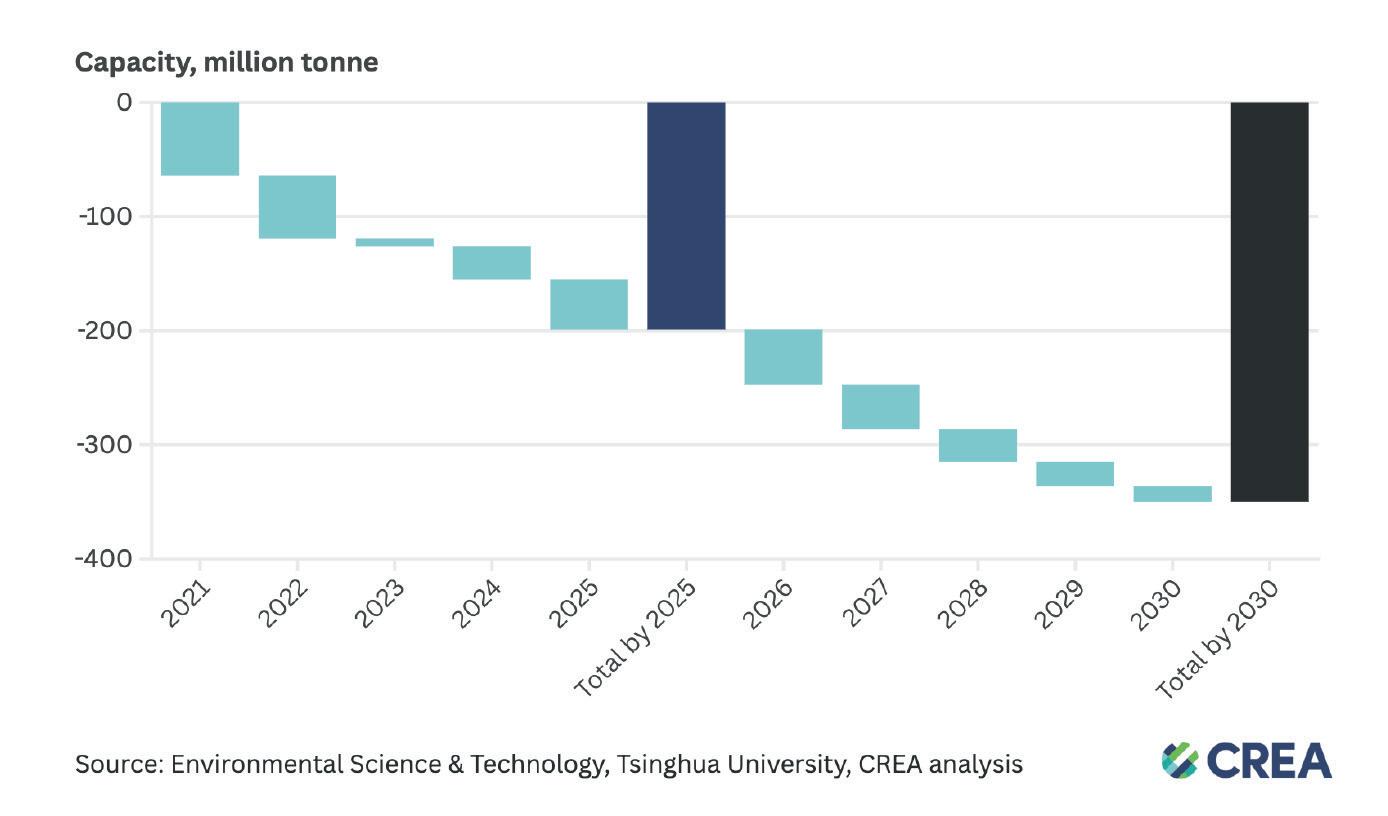
To address both overcapacity and carbon emissions, China must drastically reduce its reliance on coal-based BF-BOF technology. The government has already introduced production cuts, but these measures have been insufficient. A study by researchers from Tsinghua University has shown that a net reduction of at least 200Mt/yr of BF capacity is required by 2025 (Fig 2) –about 15% of China’s total steelmaking capacity and equal to the current total EU steelmaking capacity. A further 150Mt/yr reduction is needed from 2026 to 2030. These cuts are critical for decarbonization and improving profitability within the industry. Reducing BF capacity will help alleviate overcapacity and allow producers to focus on manufacturing higher-value, lower-carbon steel products.
In 2024, local governments approved 11.04Mt/yr of new BF capacity, which, if built, will contribute to China’s overcapacity problem. The newly approved coal-based BF projects risk becoming stranded assets, with potential losses estimated at 140 billion
yuan. This reinforces the need for stricter policies to halt the approval of new coalbased projects and focus on supporting low-carbon alternatives.
Scaling up zero-emission technologies
To meet the 2060 carbon neutrality target, China’s steel sector must significantly scale up its use of zero-emission technologies, such as hydrogen-based metallurgy.
Hydrogen metallurgy, which relies on hydrogen produced through renewable energy, holds the potential to reduce emissions by up to 90% compared to traditional BF-BOF methods. However, only a small fraction of steelmaking capacity has been dedicated to hydrogen-based processes. Between 2021 and 2024, only 2.3Mt/yr of hydrogen-based metallurgy projects were approved, far below the pace needed to meet long-term targets.
One potential solution lies in redirecting
investments away from coal-based projects and towards hydrogen metallurgy. Leading steelmaker Baowu Steel has already begun pioneering hydrogen-based steel production in Zhanjiang, with an investment of 2.15 billion yuan in a 1Mt/ yr hydrogen metallurgy project. By 2060, China will need 150Mt/yr of hydrogenbased metallurgy capacity – equivalent to 150 projects of Baowu’s Zhanjiang scale.
To achieve this, one hydrogen plant must be commissioned every quarter starting in 2023.
‘Steel Reform 2.0’: a new era of structural change
According to a January 2025 Morgan
Stanley research report, a new round of supply-side reform, ‘Steel Reform 2.0,’ could begin as early as 2025. Unlike previous rounds of reform, this phase is expected to be more cautious and focused on gradual changes, emphasising consolidation and stricter production controls based on producers’ environmental performance.
Action plan for energy conservation
Key policy developments, such as the National Development and Reform Commission’s 2024 action plan for energy conservation and carbon reduction, signal a shift towards prioritising low-carbon steelmaking methods. The Ministry of Ecology and Environment has also proposed including the steel sector in the national carbon market by the end of 2024, with the first compliance cycle due in 2025. These policies ensure the steel sector meets its emissions reduction targets and aligns with China’s broader climate goals.
Policy recommendations
To address the challenges outlined above and facilitate a smooth transition to a lowcarbon steel sector, the following policy recommendations are made:
1. Accelerate low-carbon technology adoption: Promote using EAF and hydrogen-based metallurgy technologies through targeted financial incentives and innovation-driven policies.
2. Reduce coal-based steelmaking capacity: Implement a phase-out plan for coal-based BF and BOF capacity, focusing on cutting back existing capacity and halting new projects to avoid stranded assets.
3. Foster technological innovation: Support research into alternative steelmaking methods and encourage international collaboration to enhance competitiveness and sustainability.
4. Leverage renewable energy: Capitalise on China’s expanding renewable energy capacity to drive synergies between the decarbonisation of electricity generation and industrial processes.
5. Strengthen the carbon market: Expand the carbon market to include steel, cement, and aluminium industries, transitioning from an intensity-based approach to a cap-and-trade system to ensure meaningful emissions reductions.


China’s steel sector faces critical challenges balancing production growth with environmental sustainability. Urgent reforms are needed to tackle overcapacity, reduce emissions, and accelerate the adoption of low-carbon technologies. The success of these reforms will determine whether China can meet its carbon neutrality goals and ensure the long-term competitiveness of its steel industry. �


Performances, operational reliability and quick startups are the result of 20 years of continuous research and development activities, carried out at the Danieli research center and onsite together with partnering customers. Depending on plant configuration, MIDA QLP can make use of more than 30 Danieli patents covering technological layouts, production equipment and Danieli Automation solutions, such as power, instrumentation and intelligent digital controls.
— The most efficient, digitally controlled electric steelmaking with no impact on the power grid.
— 10 m/min casting speed, allowing up to 1.5-Mtpy productivity on one casting strand, 23.5 hours out of 24 of continuous endless-casting operation.
— No gas-reheating furnace, and no induction heating during casting.
— Danieli Automation robotics and artificial intelligence for zero-men on the floor.
— Least power-consuming process with the lowest carbon footprint.
— The most competitive plant in terms of CapEx and OpEx.
With the order placed by CMC Steel for its fourth new, MIDA QLP hybrid-ready minimill, the Danieli scorecard hits 26 plants for long-product endless casting-rolling, out of 115 total minimills.
PLANTS
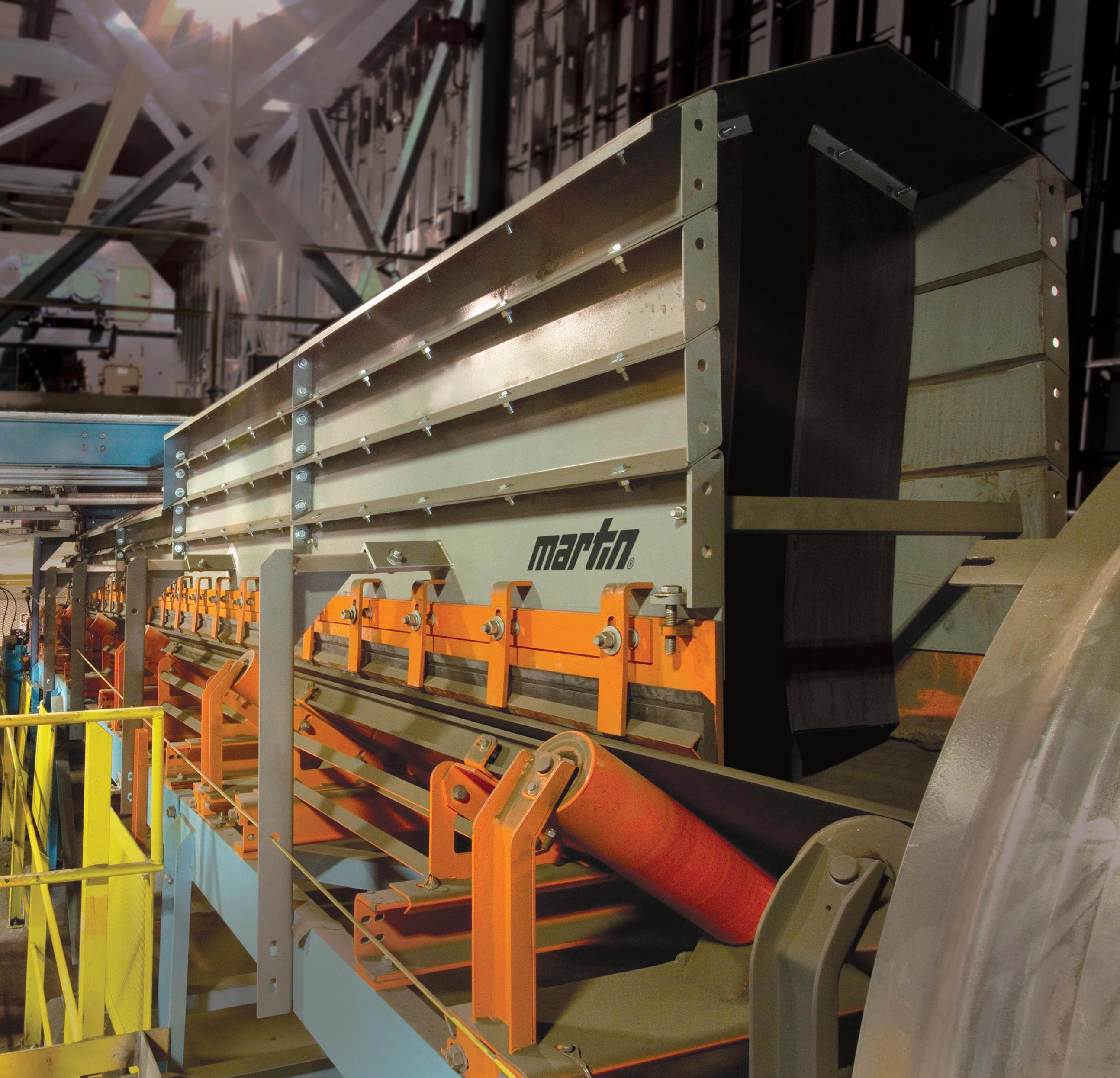
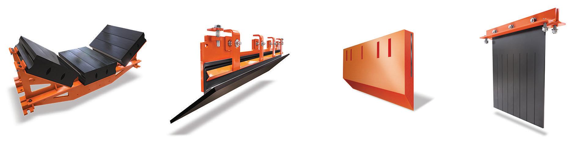
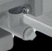
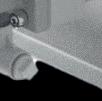
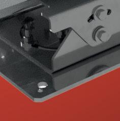
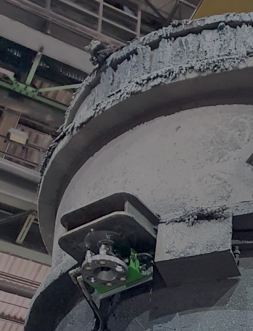
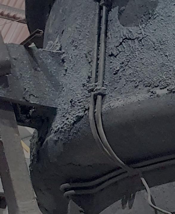
Dust and fines escaping from transfer points in steel production create a triple threat: compromising worker safety, triggering regulatory violations, and eroding operational efficiency. Martin's engineered solutions eliminate these hazards at their source.
Our modular Transfer Point Kits feature strategically configured loading, settling, and stilling zones that manage airflow at critical junctures. This primary defense is reinforced by field-proven components—including ApronSeal™dual-seal skirting, specialized impact belt cradles, dust curtains, and internal and external wear liners. This integrated containment approach creates a sealed conveyor environment that prevents dust from becoming airborne while extending equipment service life with minimal maintenance requirements.
Martin Engineering. Good thinking.
Meeting decarbonization goals will require a nuanced engagement with all the potential hydrogen usage offers, alongside consideration of the challenges faced in its adoption. By Almudena Casado1, Ricardo Baños2, and Eduardo Bilbao1
DECARBONIZING the steel industry is essential to meet global climate change targets, as it accounts for 7% of total global GHG emissions. The sector faces significant challenges due to its global competitiveness, reliance on carbon in production, and high energy consumption. The push for decarbonization is driving innovation, with solutions like renewable energy, fuels, and CO2 capture being developed. Hydrogen is emerging as a key player in this transformation.
However, the widespread adoption of hydrogen faces several obstacles. Developing low-carbon technologies, such as electrolysis, is crucial for sustainable hydrogen production. Despite its potential, hydrogen must compete with more accessible alternatives, and overcome challenges related to infrastructure, cost, and social acceptance, which is vital for its success.
The agreements from COP 28 emphasize the urgent need to triple renewable energy generation capacity and double energy efficiency by 2030. Adopting lowemission hydrogen is not just an option but a strategic necessity to meet climate goals and ensure a just and sustainable transition. Integrating hydrogen into the energy mix is crucial for achieving these targets and driving the global energy transition, particularly in decarbonizing steel production.
Currently, 70Mt of hydrogen (H2) are produced directly: 76% from natural gas primarily through Steam Methane Reforming (SMR), 23% from coal, and 1-2% from electrolysis. Additionally, 48Mt of H2 are produced as a byproduct. The annual production of H2, which is almost entirely derived from fossil fuels, results in the
IDOM Consulting, Engineering, Architecure, S.A.U.
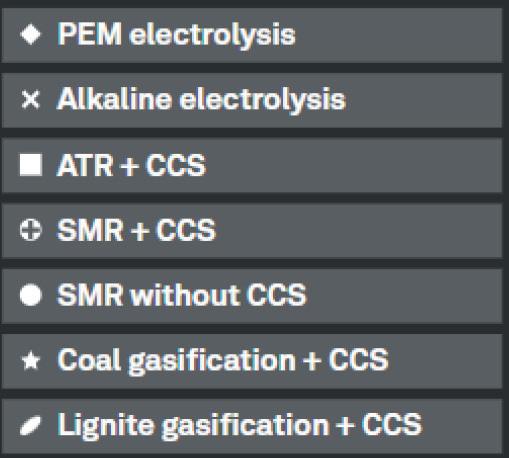
emission of approximately 830Mt of CO2 per year. There are four main technologies: SMR; Alkaline, PEM, and SOEC, with the latter being the least mature:
• Steam Methane Reforming (SMR): Methane reacts with steam at high temperatures and pressures, producing hydrogen and carbon monoxide. A common method for large-scale hydrogen production but it generates CO2 emissions.
• Alkaline Electrolysis: A simple and cost-effective process, but less efficient, which splits water into hydrogen and oxygen using an alkaline solution.
• Proton Exchange Membrane (PEM): A more efficient method with high purity, where water is split into oxygen, protons, and electrons using a special membrane that only allows protons to pass through.
• Solid Oxide Electrolysis Cells (SOEC): Uses a ceramic electrolyte at high
1. Avenida Zarandoa, 23, Bilbao, España, 48015 2. 1375 Peachtree St. NE, Atlanta, GA, U.S.A., 30309
Phone: +34 944797600 Email: metals-minerals@idom.com
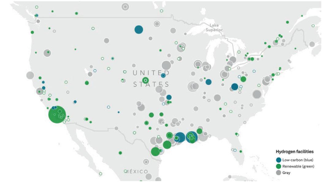
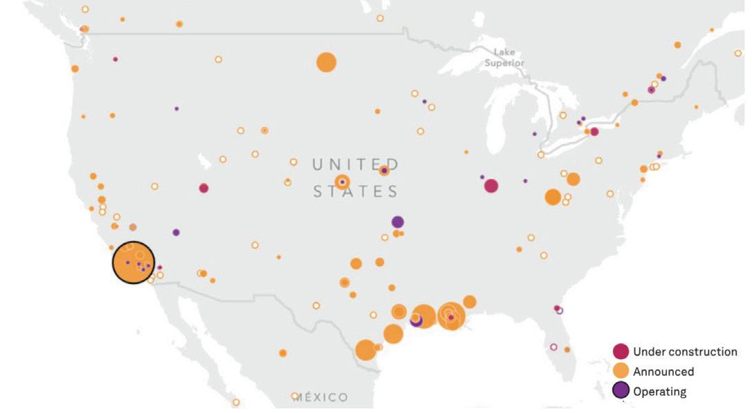
Fig 1a. Hydrogen facilities regarding their origin; Figure 1b.implementation phase.
Source https://www.spglobal.com/commodity-insights/en/news-research/special-reports/ energy-transition/atlas-of-energy-transition
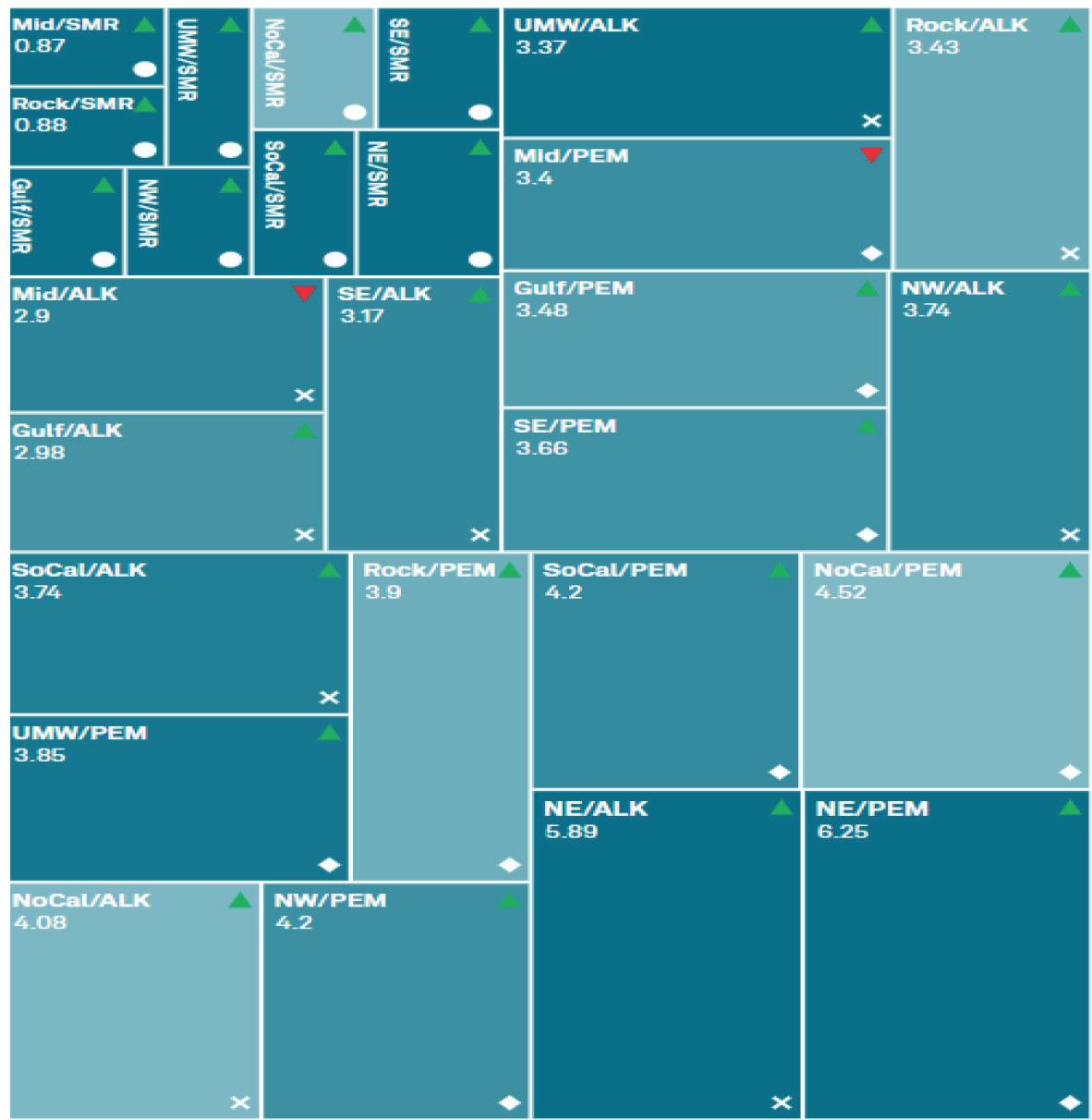
Fig 2.Hydrogen prices based on the production method in EEUU
current electrolyzers, 1 MWh can produce 220 Nm³ or 20 kg of H2. A significant portion of the cost of H2 produced from electrolyzers is electrical consumption. It is estimated that around 70% of the cost is related to electricity, while the remaining 30% is associated with CAPEX amortization and maintenance.
Fig 2 shows the differences in hydrogen prices based on the production method. Competition is emerging between technologies and regions to produce the cheapest low-carbon hydrogen (blue or green). The prices reflect monthly average production costs, including capital expenditures.
Challenges for the widespread adoption of H2 in steelmaking
Source :https://www.spglobal.com/commodityinsights/PlattsContent/_assets/_files/en/specialreports/energy-transition/ platts-hydrogen-price-wall/index.html
temperature, improving efficiency, and can be integrated with external heat sources.
As an alternative to producing H2 by breaking down water molecules, some projects are starting to look at the feasibility of extracting hydrogen buried under the Earth’s crust, similar to natural gas.
Hydrogen classification by production method:
• Grey hydrogen: Produced from fossil fuels without carbon capture and storage (CCS), resulting in CO2 emissions.
• Blue hydrogen: Produced from fossil fuels with CCS or through electrolysis using non-renewable electricity. This method
incurs high capital costs for CCS and hydrogen generation equipment.
• Green hydrogen: Produced through water electrolysis using renewable electricity. This method faces challenges related to the cost and scale of current commercial plants.
Since 2020, there has been a proliferation of clean hydrogen project proposals. Fig 1 illustrates the different hydrogen facilities based on their origin and implementation phase.
Electrolysis is recognized as a promising option for generating hydrogen from renewable sources. As a reference value for
To meet the goal of limiting global warming to +1.5ºC, it is estimated that hydrogen must account for 12% of global energy demand by 2050, with 66% being green hydrogen. This requires an electrolyzer capacity of 5,000 GW, compared to the 10 GW installed in 2023. The production of green hydrogen will require 20,800 TWh of electricity, which is equivalent to 80% of current global electricity generation.
The transition to green hydrogen in the steel industry faces several challenges. Producing green hydrogen through electrolysis is more expensive than fossil energy sources, which could lead steel plants to relocate to countries with cheaper renewable energy. Optimal locations must meet certain critical parameters, such as:
• Abundant and cheap renewable energy, as the cost of green hydrogen depends on electricity prices.
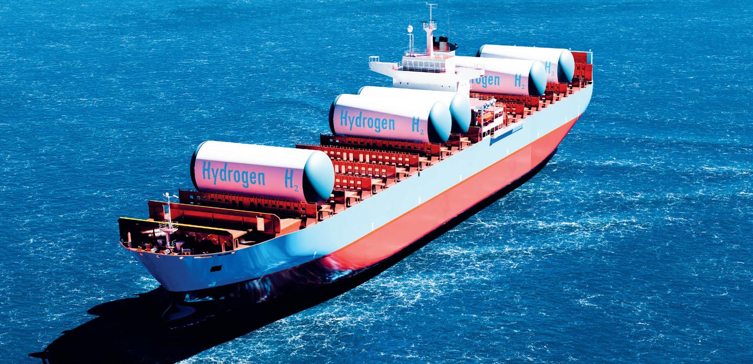
• Efficient production, storage and transportation infrastructure. Hydrogen


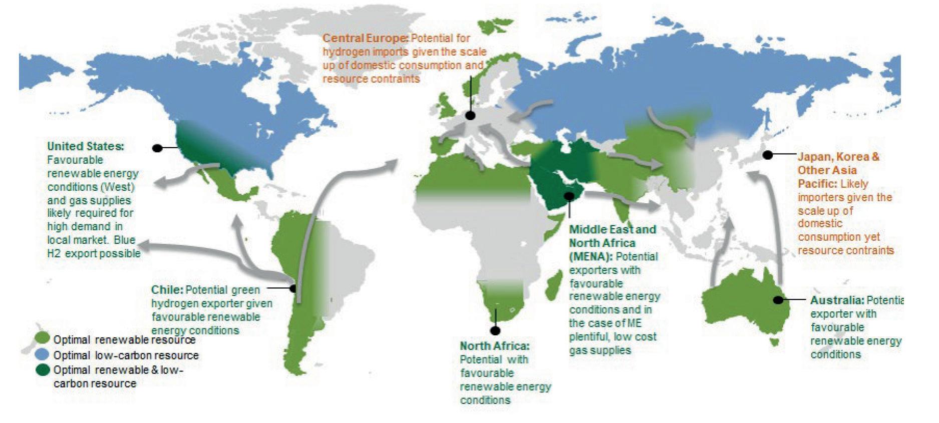
transportation via pipeline is cost-effective up to 3,000 km; beyond that distance, shipping hydrogen by sea is more economical.
• Favourable government and regulatory policies, with clear incentives and regulatory frameworks that encourage investment in green hydrogen.
• Access to international markets, with trade agreements and efficient port infrastructure for hydrogen import/export. Competitive production costs, where production efficiency, renewable electricity cost, and the scale of projects are key to reducing costs.
• Technological innovation, through investment in R&D to improve hydrogen production, storage and transportation.
• Political and economic stability, which attracts foreign investments and ensures the continuity of long-term projects.
Another significant challenge is the lack of large-scale electricity transmission infrastructure required to power
electrolyzers. Possible solutions include the development of high-capacity transmission networks or energy storage, either batteries or in the form of green hydrogen, to overcome the variability of renewable energy sources. Fig 3
The US is one of the few regions worldwide where both ‘blue’ and ‘green’ hydrogen can play a significant role as competitive low-carbon solutions. This is due to the country’s relatively low-cost natural gas and onshore CO2 storage capabilities, as well as affordable renewable energy sources in key regions, both essential for producing blue and green hydrogen.
2. Use of hydrogen in the steelmaking industry
Hydrogen can replace carbon as a reducing agent and in combustion processes in the steel industry. Here are some detailed applications:
As a reducing agent:
Traditionally, coal has been used as a
reducing agent in steelmaking, leading to significant carbon emissions. Hydrogen offers a cleaner alternative, as it can reduce iron ore to iron while producing water vapour instead of carbon dioxide.
Use of hydrogen in blast furnaces:
Hydrogen can serve as a substitute for coke in blast furnaces by injecting hydrogenrich streams, thereby reducing coke consumption. However, the endothermic nature of hydrogen necessitates additional energy to sustain high temperatures, posing challenges to the heat balance. Moreover, hydrogen must deliver the same consistency as coke to maintain furnace stability and efficiency.
� Ongoing projects:
• COURSE50: This project aims to reduce blast furnace CO2 emissions by using hydrogen reduction technology combined with CO2 separation and recovery. It has achieved a 10% reduction of CO2 emissions in experimental settings and is working on scalable solutions.
• H2Stahl: This project focuses on integrating hydrogen into the blast furnace process to explore the technical and economic feasibility of using hydrogen as the primary reducing agent, with the goal of significantly lowering the carbon footprint of steel production.
Use of hydrogen in direct reduction plants:
Hydrogen and carbon are both suitable reductants for iron ore, but they differ significantly in their by-products. Hydrogen emits water vapour instead of CO2, making
it a cleaner alternative. However, additional energy is required, given the endothermic nature of the reaction with hydrogen. It is estimated that for every cubic metre of natural gas replaced, three cubic metres of hydrogen are needed.
Advantages:
Hydrogen can be used up to 100% as a reducing gas in the direct reduction process without major modifications, offering a seamless transition to a cleaner alternative. The CO2 mitigation potential is 100%, significantly reducing the carbon footprint of steel production. This makes hydrogen
reduced sponge iron production and a pilot hydrogen storage facility. HYBRIT has the potential to cut Sweden’s CO2 emissions by 10% and Finland’s by 7% when fully implemented.
• The SALCOS® project by Salzgitter AG focuses on producing climate-neutral steel using hydrogen-based direct reduction methods. It includes constructing a 100 MW electrolysis plant to generate around 9kt of green hydrogen annually from 2026, aiming for over 95% reduction in CO2 emissions and setting a benchmark for sustainable steel production.
an attractive option for industries aiming to meet stringent environmental regulations and sustainability goals.
Disadvantages: As hydrogen usage increases, the carbon content in direct reduced iron (DRI) decreases. Carbon is essential in electric arc furnaces (EAF) because it combines with oxygen to provide energy for melting. Producing DRI with 0% carbon would impact the subsequent EAF steelmaking step, requiring changes to the process, with alternative (and sustainable) carbon addition sources, such as biocharge and alternative additives for foaming, potentially increasing the EAF process costs. OEMs recommend a minimum practical carbon content of 1-1.3% for EAF.
Projects:
• The HYBRIT project, launched by SSAB, LKAB, and Vattenfall, aims to produce fossil-free steel using hydrogenbased processes, achieving milestones like the world’s first pilot-scale hydrogen-
• Chemical energy injectors in EAFs: Hydrogen can be used as fuel in electric arc furnaces (EAFs) to improve combustion efficiency and reduce carbon emissions. This technology is adaptable for low, medium, and high-pressure applications.
• Ladle and tundish drying and preheating: Hydrogen combustion provides a clean and efficient heat source for ladle drying and preheating, crucial for maintaining efficiency and quality in steel production.
• Oxyhydrogen cutting torch: Combines hydrogen and oxygen to produce a hot flame for cutting and welding steel with precision. This method is safer and more environmentally friendly than traditional acetylene torches.
• Reheating furnaces: Hydrogen combustion in reheating furnaces heats semi-finished products before rolling, reducing CO2 emissions and improving thermal efficiency and temperature uniformity.
Green steel projects aim to produce steel with significantly lower carbon emissions by using renewable energy sources and innovative technologies. These initiatives are essential for achieving climate goals and transitioning to a more sustainable industry. Stegra project: The Stegra project, formerly known as H2 Green Steel, is a groundbreaking initiative to decarbonize the steel industry. Located in Boden, Sweden, this project includes a 2.1Mt/ yr direct reduction iron (DRI) production facility powered by a 760 MW hydrogen production plant. The project also features a 2.5Mt/yr steelmaking and continuous strip production (CSP) facility, various cold finishing facilities, a plant power distribution grid, and comprehensive plant infrastructure and water systems. Stegra aims to set a new industry standard by producing near-zero emission steel and significantly reducing steel emissions by over 7Mt/yr.
GravitHy project: The GravitHy project, backed by a consortium of industrial leaders, plans to build, own, and operate its first green iron and steel plant in Fossur-Mer, Southern France. This project includes a 650 MW electrolyzing plant for green hydrogen production, which will feed a 2Mt/yr DRI production facility. The DRI produced will be used either on-site as feedstock for green steel or traded globally as hot-briquetted iron (HBI). The project also encompasses plant infrastructure, port, and logistics facilities. GravitHy aims to support the decarbonization of the steel industry and contribute to Europe’s ‘Fit for 55’ ambitions.
4. Conclusion:
Decarbonizing the steel industry is essential to meet climate targets, with hydrogen playing a crucial role despite challenges in cost, infrastructure, and social acceptance. Since 2020, clean hydrogen projects have surged, focusing on hydrogen production from renewable resources via electrolysis. Hydrogen can replace carbon at every stage of the steelmaking process, significantly reducing CO2 emissions. Green steel plants, such as Stegra and GravitHy, are being built to produce near-zero emission steel. IDOM leads steel industry decarbonization and digitalization, supporting clients to reduce emissions, improve efficiency, and maintain quality. �


www.HilcoIndustrial.com
‘DANIELI’ 600,000 TPY FLEXIBLE SECTION ROLLING MILL (2011)
120TPH Furnace, Breakdown Mill, Ultra-Flexible Reversing Mill, Continuous Finishing Mill, Automatic Stacker at Stahl-Gerlafingen, Switzerland.
‘NKK-SMS’ COMPACT STRIP PRODUCTION PLANT (1995/2011)
150T Electric Meltshop, Thin Slab Cast & Rolling, Thick Slab Caster & Skin Pass Mills at Hyundai Steel Dangjin, South Korea.
‘HAEUSLER’ 60,000 TPY LSAW WELDED PIPE PRODUCTION LINE (1991/2014)
Plate Edge Milling, 3-Roll Bending, Inside & Outside Welding, Copander, Testing Equipment and more at Hyundai RB Ulsan, South Korea.
‘CONCAST-DAVY-UNITED-FATA’ SLAB CASTER, HOT STRIP MILL & COLD ROLLING COMPLEX
Slab Caster, Hot Strip Mill, Tandem Cold Mill, Annealing & Coating Lines at CAP Acero Huachipato, Chile.
Available Soon: Wide Hot Strip Mill, Galvanizing Lines 20-Hi Sendzimir Mills, Skin Pass Mill and much more.


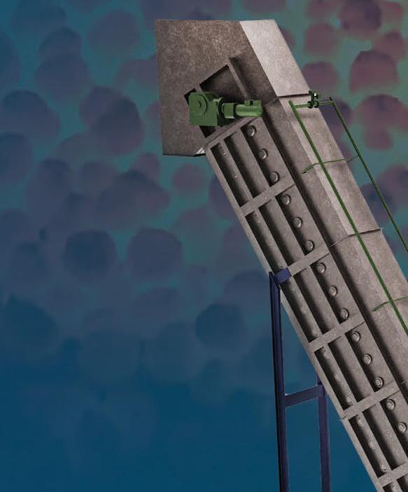


While much of the attention about the Trump 2.0 presidential administration and its impact upon on the US steel industry has recently been upon trade and regulatory policies, particularly various import tariffs, opinions have varied on what impact the administration’s policies will have upon the decarbonization of the industry. By Myra Pinkham*


“I BELIEVE that overall, at least over the short-to medium term, the Trump administration’s policies, particularly the expected tariffs upon steel and steelcontaining downstream products, will make US steelmakers (and to a lesser extent US steel service centres and processors) more profitable,’’ Ryan McKinley, a senior steel analyst with CRU said, although he admitted that it could make things more challenging for steel buyers.
Philip Bell, president of the Steel Manufacturers Association (SMA), said that overall there are three key areas of focus by the Trump administration that will impact the US steel industry – trade policies including tariffs, tax policies such as moving to extend 2017 tax credits, and a focus upon regulatory certainty and rolling back regulatory overreach including certain recently enacted environmental policies.
Overall, talk about the environmental implications of the Trump administration’s policies have taken a backseat to the recent import tariff volatility, Philip Gibbs, a senior equity analyst for KeyBanc Capital Markets, declared, adding that many steelmakers have been less vocal about latching onto any big time green initiatives or lower carbon emission technologies even though they are continuing to work on such things. “It is just that trade issues have been taking the centre stage.”
While there continues to be some uncertainty about what tariffs and other trade action will be implemented and
over what time period, Ashimi Tyagi, an economics associate director of S&P Global Market Intelligence’s pricing and purchasing service, said that once they are, there should be a significant increase in steel prices, as has already started to occur. Although, Tyagi added that this could be short-lived as idle and underutilized capacities gradually come back online.
“The long-term outlook remains complex,” Tyagi said. “That is particularly in light of tariff responses from other trade partners, sustainability challenges and regulatory changes,” she said. “Additionally, we can expect reorientation of supply chains, especially if the process of country exemptions and product exclusions remains rescinded.”
The US steel industry supports this. In fact, on 7 March, the chief executive officers of nine steel companies – Nucor, Steel Dynamics, US Steel, Cleveland-Cliffs, Commercial Metals, Metallus, North American Stainless, Tenaris and Zekelman Industries – sent Trump a letter requesting that he resists any requests to grant exceptions, exclusions, or quotas related to his tariffs – unlike what occurred in 2018 with his original Section 232 tariffs.
Also, several steel trade associations, including the SMA, the American Iron and Steel Institute (AISI), Specialty Steel Industry of North America, American Institute of Steel Construction, and US OCTG Manufacturers Association, wrote Trump a similar letter.
*North America correspondent, Steel Times International.
On the other hand, there are some growing concerns about the economic implications of the tariffs – not just steel tariffs, but tariffs on other products as well – given that they are seen as being inflationary in nature. In March, shortly before the steel tariffs’ enactment, there were renewed concerns about their impact upon consumer spending and if this could in turn increase the possibility of an economic recession later this year.
When it comes to the environmental policies, Kevin Dempsey, president and chief executive officer of AISI, maintained that over the past four years various government entities, especially the Environmental Protection Agency, have imposed ‘burdensome and often technically unrealistic regulatory demands on steelmakers.’
He said that many of these regulations, particularly those related to air emissions limits, pose significant challenges for domestic steel production despite numerous governmental analyses indicating that there are minimal health risks from these operations.
SMA’s Bell said that one example of this is related to the National Ambient Air Quality Standard, stating that when the Biden administration ‘prematurely’ changed the PM2.5 threshold for particulate matter to its lowest possible level (9 micrograms per cubic metre), a level so low that it puts companies in some regions of the country out of attainment, they then faced the
possibility of being unable to get the air quality permits needed to build new steel mills or expand existing facilities.
build its new Brandenburg, KY, plate mill. There is also some speculation that Trump could rescind some of the still

Both the AISI and SMA said that they have been urging the Trump administration to rollback some of these regulations and adopt what they see as a more sensible approach. Dempsey said that he believes that the government should engage in a new strategy that will balance environmental protection with reasonable regulations, while also acknowledging the American steel industry’s global leadership in clean steel production.
There have, however, been some concerns that under the new administration the recent green push could stagnate. In fact, KeyBanc’s Gibbs said out of the gate that seems to be the case, with Trump’s platform being less focused upon the subsidization of renewable energy sources and more so on ‘drill baby, drill’.
This, CRU’s McKinley noted, could be seen from some of Trump’s executive orders that could adversely affect future wind power projects, including one early order prohibiting leases, loans, and incentives for wind projects on federal lands, which he said will put an end to any new offshore wind projects in the US, therefore slowing US steel plate demand. He noted that prior to this executive order, a number of offshore wind projects had been planned for the next 10 years and that demand was one of the motivating factors for Nucor to
unspent funding from the Inflation Reduction Act (IRA), including incentives for renewables and some monies being managed by the Department of Energy to fund clean energy demonstration projects. But Gibbs said that could be difficult to do as some of those projects are in red states, and some Republicans in those states want them to proceed.
SMA’s Bell agreed, noting that while the Trump administration might look to rollback a portion of that spending, he doesn’t think that it wants to rescind the whole thing given its realization that some elements of the IRA are very beneficial to US industry, including the US steel industry.
Rather, he said it appears as if the Trump administration will take a more surgical approach, and that some of the allocated monies might not actually do what it had been intended to do, including promoting steel industry growth and supporting lower emissions. Bell added that in particular, some electric vehicle subsidies and incentives could be put on the chopping block, as well as funding for wind and solar projects.
Another question is what impact the Trump administration pulling out of the Paris Climate Agreement could have. Bell said that he doesn’t believe that is an indication of the administration having

less of a commitment to environmental issues, but rather the US avoiding putting itself at a competitive disadvantage, due to China and India’s non-participation in the Agreement.
On the other hand, S&P Global’s Tyagi maintained that its withdrawal could lessen the urgency for decarbonization efforts, not only in the US but also in other steel-producing countries. This, she said, could potentially lead to a domino effect of countries retracting their commitments to Nationally Determined Contributions (NDCs). “Were this to occur, global climate mitigation and adaptation efforts could receive a severe blow,” Tyagi said, as international climate financing could dry up.
However, Gibbs said that even with less government incentives that doesn’t mean that steel mills and steel end users won’t focus upon being greener on their own. “It is just that I don’t think those preferences will be stimulated or fostered by government dogma,” he concluded, as had been the case during the Biden administration.
Adina Renee Adler, executive director

of the Global Climate Council, said that overall the new administration will not have much of an impact upon the US steel industry’s focus on decarbonization. In fact, the administration’s planned easing of regulation could make it easier for US steelmakers to pursue business strategies to further lower their carbon footprint –something that she noted has been more driven by market forces, including that over 70% of US steel is produced via electric arc furnaces (EAFs).
That is essentially flipped from the global average of about 25% of steel produced via EAFs and 75% produced via blast furnaces. In fact, Tyagi said that as of 2023, only China produced 9.9% of its steel via EAFs. Similarly, the Japanese EAF share was only 26.2%, the EU-27 share was only 44.8% and India’s share was 56.4%.
Given that EAF steel is largely scrap-based and with US integrated steelmakers such as US Steel and Cleveland-Cliffs looking to make their steel greener, this has resulted in the US reportedly also producing the cleanest, lowest carbon steel in the world. In fact, Adler observed that the average
The US will increase its planned 25% tariffs on Canadian steel and aluminium to 50%, President Trump said in a post on his Truth Social account, in a response to Ottawa’s retaliation to US tariffs imposed last week.
emissions of US-based steelmaking is only about 1.7 tonnes of carbon dioxide equivalent per tonne of steel produced compared with the global average 1.9-2.0 tonnes of carbon dioxide equivalent per tonne of steel produced.
AISI’s Dempsey said it remains a key goal for the American steel industry to be committed to leading the way in the production of low-carbon emissions steel, including the exploration of innovative approaches to producing steel as efficiently as possible, adding, “We look forward to working with the new administration to further these goals.”
That said, CRU’s McKinley said that while the US steel industry is already the greenest in the world and that he doesn’t believe that any of the administration’s policies will impact that position, he questioned whether the mills will be engaging in any significant voluntary top-down efforts to make it greener than it already is, explaining that while steel buyers like the idea of zeroemissions steel, they won’t pay a premium.
Also, Tyagi noted that the Trump administration’s push for increased oil
and natural gas drilling could divert some resources from renewable energy investments, further complicating the industry’s green transition, as could the anticipated reduction or complete removal of the funding of some decarbonization projects previously supported by the IRA and the bipartisan IIJA infrastructure bill.
Some others, however, see it differently. For example, KeyBanc’s Gibbs said that with or without governmental incentives, he believes that as it follows the money, the US steel industry will continue to get greener, maintaining that the US businesses that tend to consistently make the most money are those that don’t pollute. “So, as they look to run a more sustainable business from a profit standpoint, the outlook is also better for the environment.
SMA’s Bell said that his association’s members will continue to be committed to producing clean, safe, and sustainable steel, adding that he believes that overall the opportunities under the Trump administration are great, maintaining that Trump understands the steel industry and is committed to supporting it. �


Future Steel Forum 2025, our seventh live event, unites decarbonization and digitalization in modern steelmaking. With presentations from leading steelmakers including home-grown Spanish company CELSA Group as well as newcomers to the world of green steelmaking like Hydnum Steel, and not forgetting other leading European players and larger Far Eastern businesses, such as JFE Steel, it looks as if the Forum will score big with delegates once again. Secure your spot today!
SPONSOR OR EXHIBIT: For any exhibition or sponsorship opportunities, contact Paul Rossage paulrossage@quartzltd.com +44 (0)1737 855116


WHAT LAST YEAR’S ATTENDEES HAD TO SAY…
“Very well organized event with a good line of speakers focused on digitalization and decarbonization.”
Scan the QR code to preview the conference programme, exhibitor list and to purchase your ticket


“Great immersive atmosphere and excellent platform to learn and network.”
“Unique blend of upcoming technologies, challenges and the latest innovation in digital transformation for the iron and steel industries.”
“A good mixture of high-level presentations, panels and networking opportunities at an excellent location.”


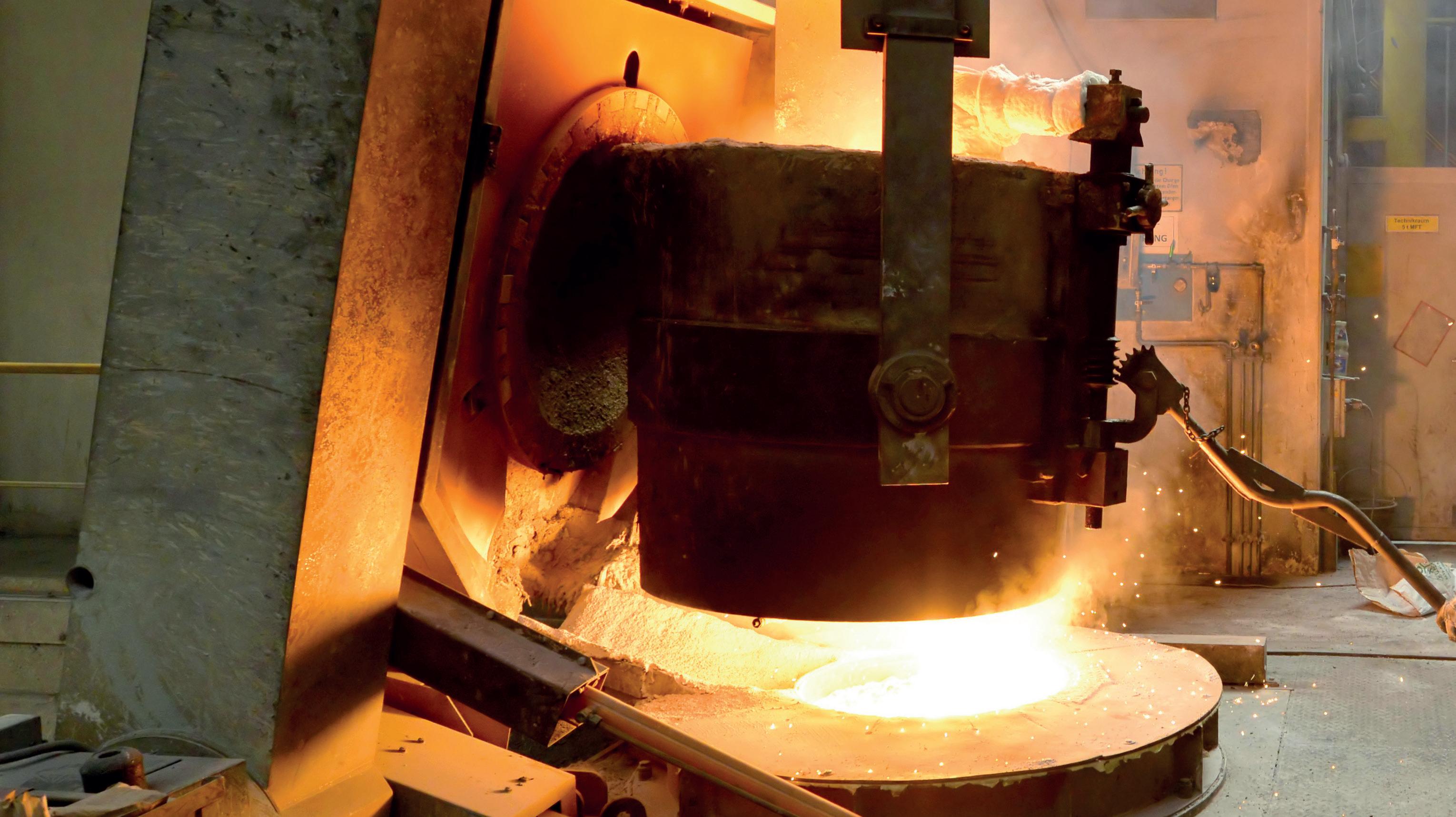
Vacuum-tank degassing offers better performances in desulfurization and nitrogen removal, and allows raw material flexibility, at lower CapEx and OpEx. By
VACUUM treatment is critical to achieving the lowest levels of carbon, sulphur, hydrogen, and nitrogen, together with the highest level of steel cleanliness. One vacuum degassing process based on liquid steel recirculation is the RH process (with/ without oxygen supply). The second most common degassing process is ‘Vacuum Tank Degassing’ (VTD process). The focus of this article is on the ability of both degassing processes to treat steel melted in an electric arc furnace (EAF).
The different capabilities of RH and VTD to remove nitrogen and the impact on overall steel quality and cost control are key drivers for proper selection between the two different vacuum refining techniques. CO2 footprint reduction in steelmaking and adoption of the EAF in place of the basic oxygen furnace (BOF) process, together with a shortage of clean and suitable scrap, and the limited availability of high-quality DRI and/or HBI needed for EAF melting, are the main variables to be considered when evaluating a degassing project.
Bojan Vucinic*
Flat-product quality requirements will not change due to adoption of EAF melting. An EAF-based process together with properly selected secondary refining units must fulfil the same quality requirements as BOF-based melt shops.
Lack of sulphur removal and limited nitrogen removal during the RH vacuum process cannot be considered a disadvantage for a BOF-based melt shop as the BOF process can achieve very low nitrogen contents due to high carbonremoval rates, and very low sulphur contents based on deep sulphur removal from hot metal. The ability of the RH technique to achieve ultra-low carbon contents needed for non-stabilized, interstitial-free grades is the main reason to select such a degassing unit as part of a BOF melt shop.
An EAF’s ability to produce highquality long products is an established
fact. Over the last 10 years, EAFs have become the melting units for flat products, including automotive grades. Continuous improvements in the EAF process, different furnace designs supported by customized chemical packages, and sophisticated process controls are reasons to believe in the future of EAFs for producing lowcarbon grades with ultra-low levels of nonmetallic impurities.
The possibility to achieve low carbon contents at the end of steelmaking with reduced carbon versus oxygen ratio, together with low final phosphorus content, is already confirmed (1)
Is it enough just to replace the BOF with an EAF? How challenging is it to manage limited availability of raw materials and at the same time keep melt shop flexibility as high as possible? Those are key questions during the evaluation of the best technique.
Degassing process during VTD and / or RH type of process
Quite often the optimal degasser choice is
*Senior manager, process technology, Danieli, Italy b.vucinic@danieli.it +39 0432 195 5519.
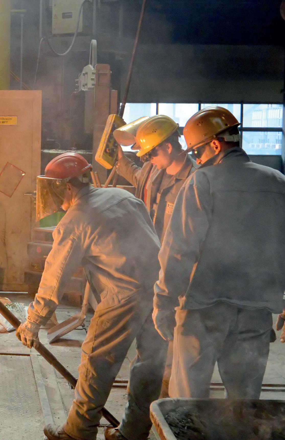
obvious. This choice is typically based on the type of melting furnace, the production programme, the metallurgical operations, design of existing equipment, and according to the metallurgical background and experience of the steelmaker. In a scenario where both types of degassers may be applied, all the individual characteristics like material flow, productivity, the share of vacuum-treated steel in the total production, the melt shop layout, or the location of the steelmaker’s plant must be discussed in correlation to arrive at an optimal solution.
RH vs. VTD – different nitrogen removal patterns
Nitrogen removal during RH degassing, as part of a BOF-based melting process, has never been extensively monitored, mainly because of already low nitrogen content prior to tapping from the BOF. As the steel outputs and the nitrogen and sulphur contents are different than for EAF melting, nitrogen removal during degassing became important.
To understand better the reasons for different nitrogen patterns for two different degassing units, we should understand the impact of equipment design on metallurgical performances and process behaviour as well. The RH vacuum degassing unit has much higher ‘free volume’ above the treated steel as compared with the VTD degassing unit. The best way to reduce partial pressure of nitrogen and achieve low final-nitrogen content is to control the amounts of oxygen, nitrogen, and argon content in the off-gas.
During the VTD process, three distinct phases shall be considered:
> Phase 1: Impact of inlet nitrogen amount; higher nitrogen content before degassing will promote higher nitrogenremoval rate;
> Phase 2: Strong impact of argon bubble geometry;
> Phase 3: Low nitrogen level; to be able to have deep nitrogen removal, partial pressure of nitrogen must be reduced.
Grades for automotive applications, home appliances, and tinplate grades (grades without any carbon removal under vacuum), usually have low, maximumallowed nitrogen content and high
cleanliness requirements. To be able to achieve low final nitrogen content (below 40 ppm after degassing process), the final phase (phase 3) of nitrogen removal under vacuum is crucial. Fig 1
There is a clear difference between the VTD and RH processes regarding the ability to remove nitrogen, with typical nitrogen content before degassing in a range of 70÷100 ppm, and with sulphur content less than 40 ppm, as shown in Fig 2
As explained above, to achieve extremely low final-nitrogen content, partial pressure of nitrogen must be reduced by increasing the argon content in off-gas.
Nitrogen removal based on vacuum tank degassing is higher compared with nitrogen removal based on liquid steel recirculation under vacuum. The reasons for this difference could be:
> RH – Higher ‘free volume’ above steel level, as compared with VTD equipment design;
> Higher leak rate, in the case of RH.
The impact of leak rate on lower nitrogen removal during the RH degassing process is already recognized and confirmed (2)
During production of high-quality flat products, it is unlikely to encounter nitrogen contents more than 80÷100 ppm at the end the LF process. Most flat products could have an even lower nitrogen content prior to degassing mainly due to a higher application of clean and carbonbased raw material during EAF melting. Fig 3
With nitrogen content prior to the vacuum process in the range of 50 ppm, nitrogen removal during the RH process is negligible.
Nitrogen removal during vacuum tank
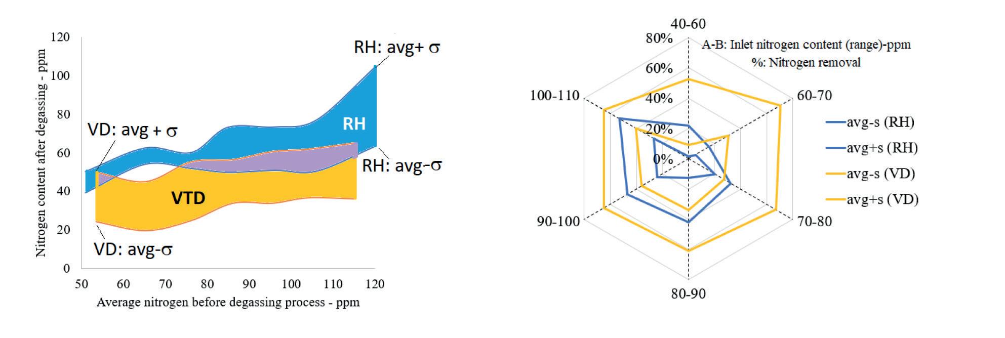
Fig 1: Nitrogen removal during RH and / or during VTD process
Nitrogen content after degassing vs. different inlet nitrogen content (note: considered sulphur content for RH treated grades is lower than sulphur content for tank degassed grades).
Nitrogen removal for different range of inlet nitrogen content (VTD vs. RH, based on low-sulphur grades only).


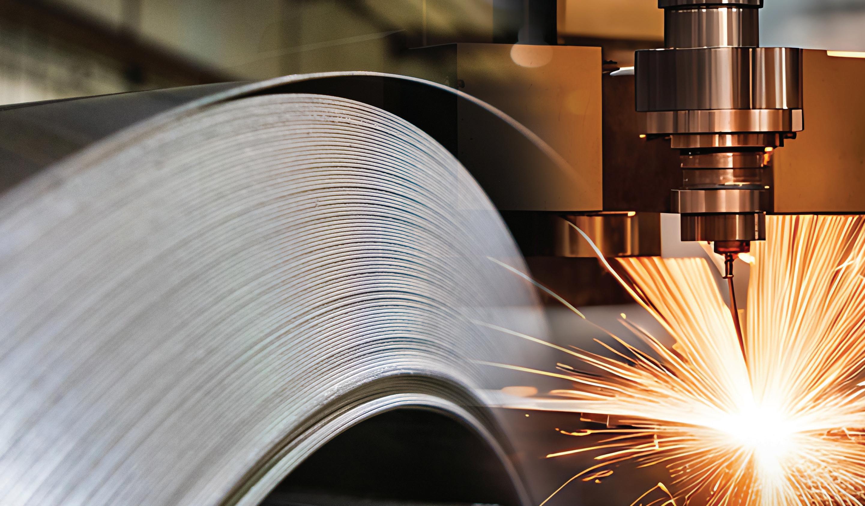


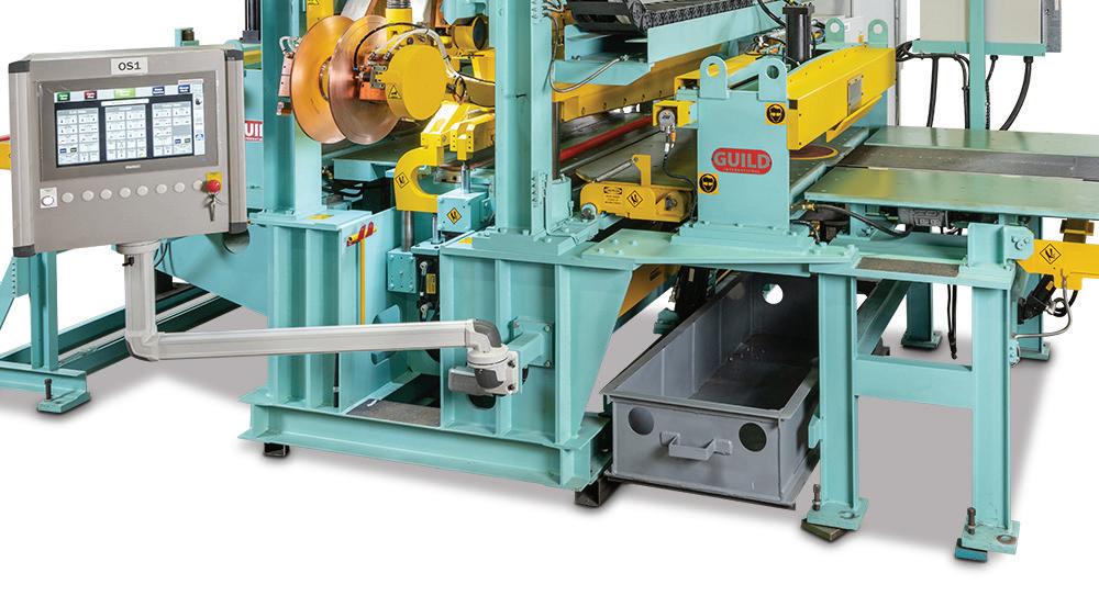

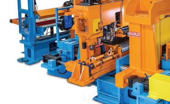
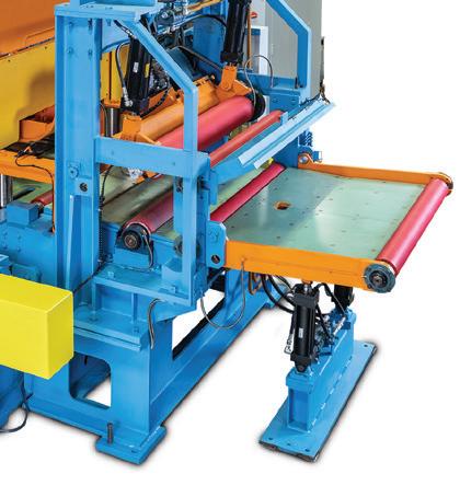
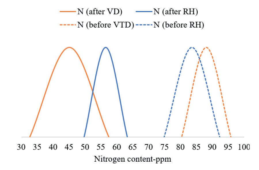
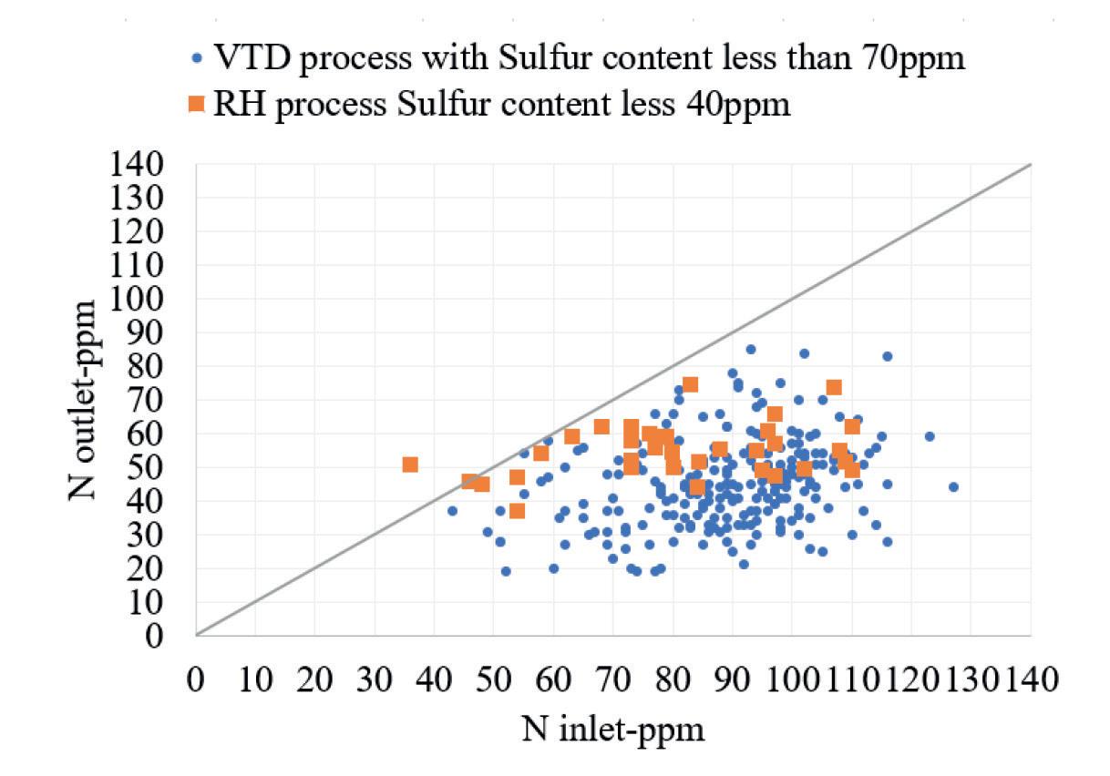
degassing is better than nitrogen removal during the RH process. This is especially valid for steel grades with low final nitrogen requirements or for grades where inlet nitrogen content at the vacuum degassing unit is lower than 70÷80 ppm.
It is possible to achieve low metallic residual contents for most flat products based on a proper ratio of carbon-based clean material and selected scrap during the EAF process. By increasing the contribution of clean material during EAF melting, nitrogen content before tapping is lower. With BOF melting, low sulphur contents are possible prior to tapping thanks to the possibility for high levels of sulphur removal from hot metal. With the EAF as the primary melting unit, low sulphur content is obtained during secondary metallurgy. The influence of sulphur on nitrogen removal during different vacuum degassing processes is reported below.
Another, important indication from the chart below is the need for ultra-low
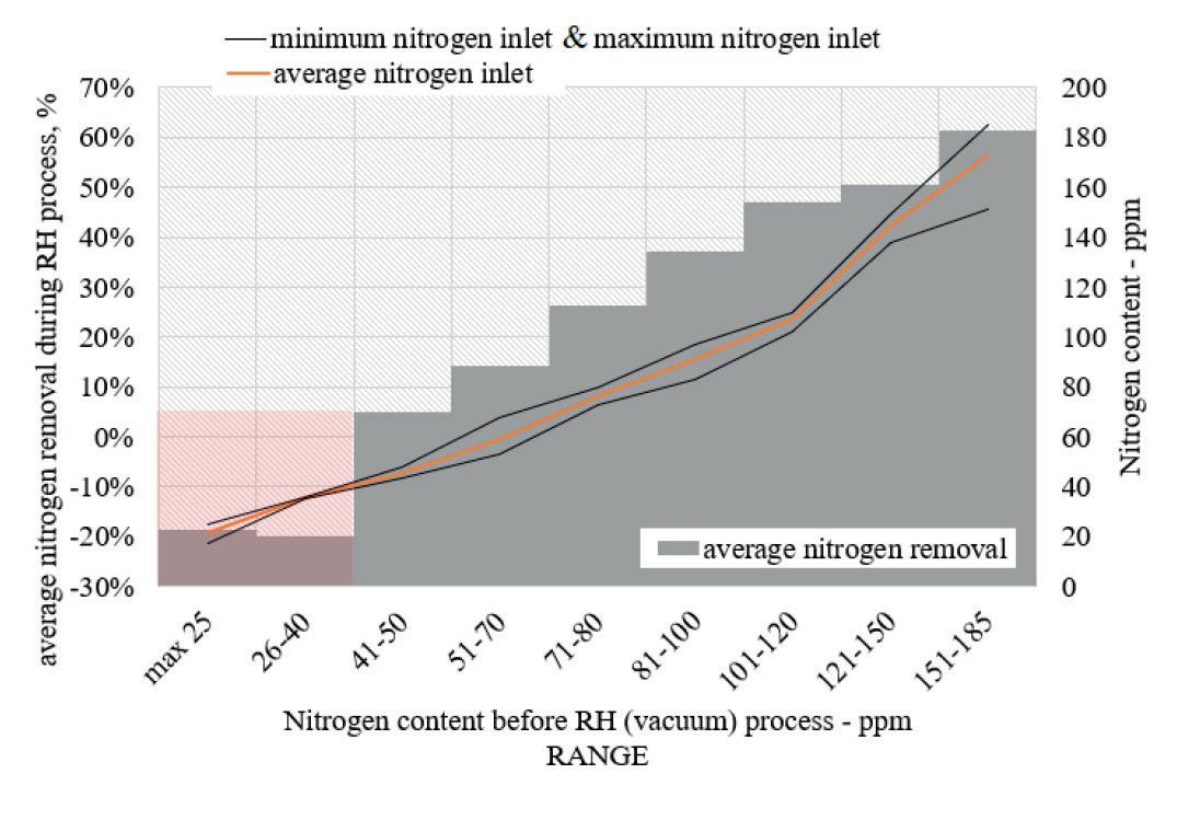
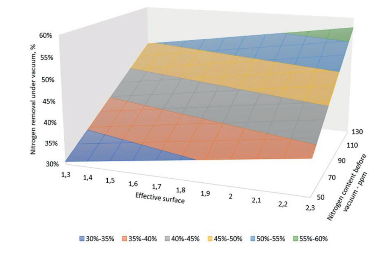
The purpose of this chart is to demonstrate trend only.
sulphur content prior to RH degassing. However, nitrogen removal during vacuum tank degassing is better with higher sulphur content prior to vacuum treatment. Fig 4
Nitrogen removal under vacuum for VTD is easier to control than nitrogen removal during the RH process. At the same time, the VTD equipment is less complex and more ‘user-friendly.’ The removal rate for nitrogen can be described by a first order differential equation:
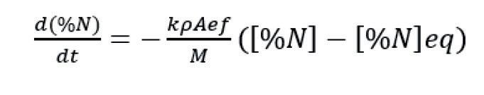
where [%N] is the concentration of nitrogen in the steel, k is the mass transfer coefficient, ρ is the density of the steel, Aef is the effective reaction area, and [%N] eq is the theoretical equilibrium content of nitrogen.
The effective reaction area is influenced by the exposed surface and the concentration of active surface elements, like sulphur and free-oxygen content. Slag
viscosity, slag conditions with the argonstirring pattern defined by the number of porous plugs, and the argon-stirring flow rate all have a direct impact on the exposed steel surface.
The impact of the effective surface together with nitrogen content are reported in Fig 5. The chart shows the nitrogen removal rate with fixed temperature, fixed vacuum time, and with different sulphur content prior to the vacuum process (as part of ‘effective surface coefficient’)(1)
There is no difference between the RH and VTD processes in regard to hydrogen removal. Both are highly efficient. Hydrogen removal is driven by pressure, circulation rate (for RH) or exposed surface (VTD process), and duration of deep vacuum time. However, Fig 6 shows a statistical evaluation of hydrogen content before and after degassing for both vacuum processes. Low hydrogen content is achievable


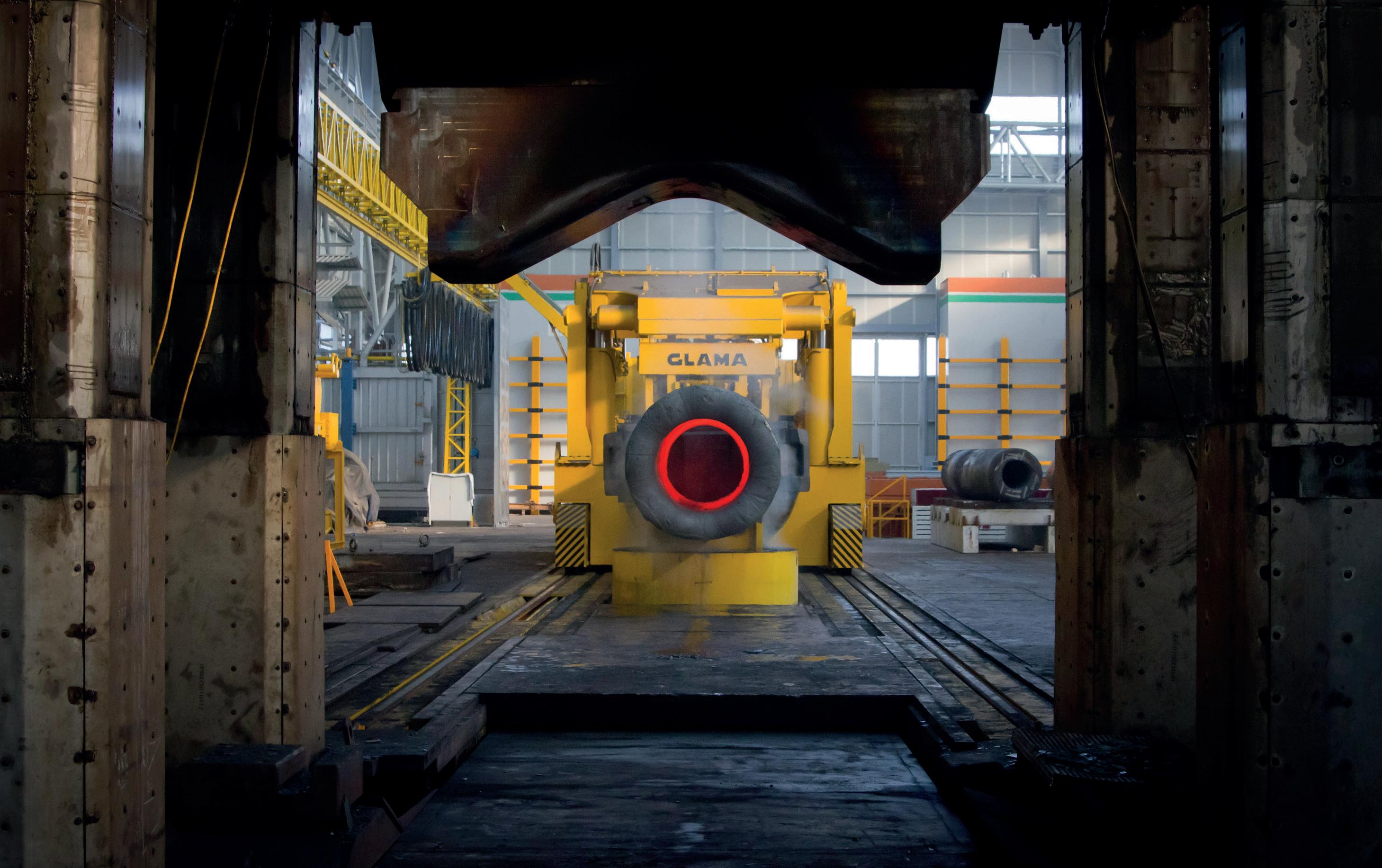


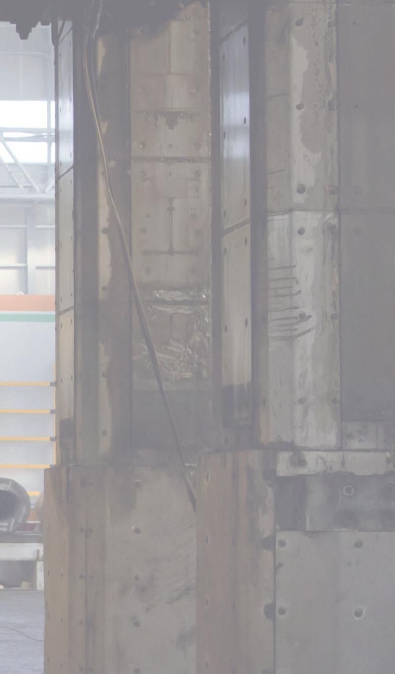
GLAMA Maschinenbau GmbH
Hornstr. 19, 45964 Gladbeck, Germany fon: +49 2043 9738 0 fax: +49 2043 9738 50
GLAMA Maschinenbau GmbH
email: info@glama.de
Hornstr. 19, 45964 Gladbeck, Germany
GLAMA USA Inc.
fon: +49 2043 9738 0 fax: +49 2043 9738 50 email: info@glama.de
60 Helwig St., Berea, Ohio 44017 fon: +1 877 452 62 66 email: sales@glama-us.com


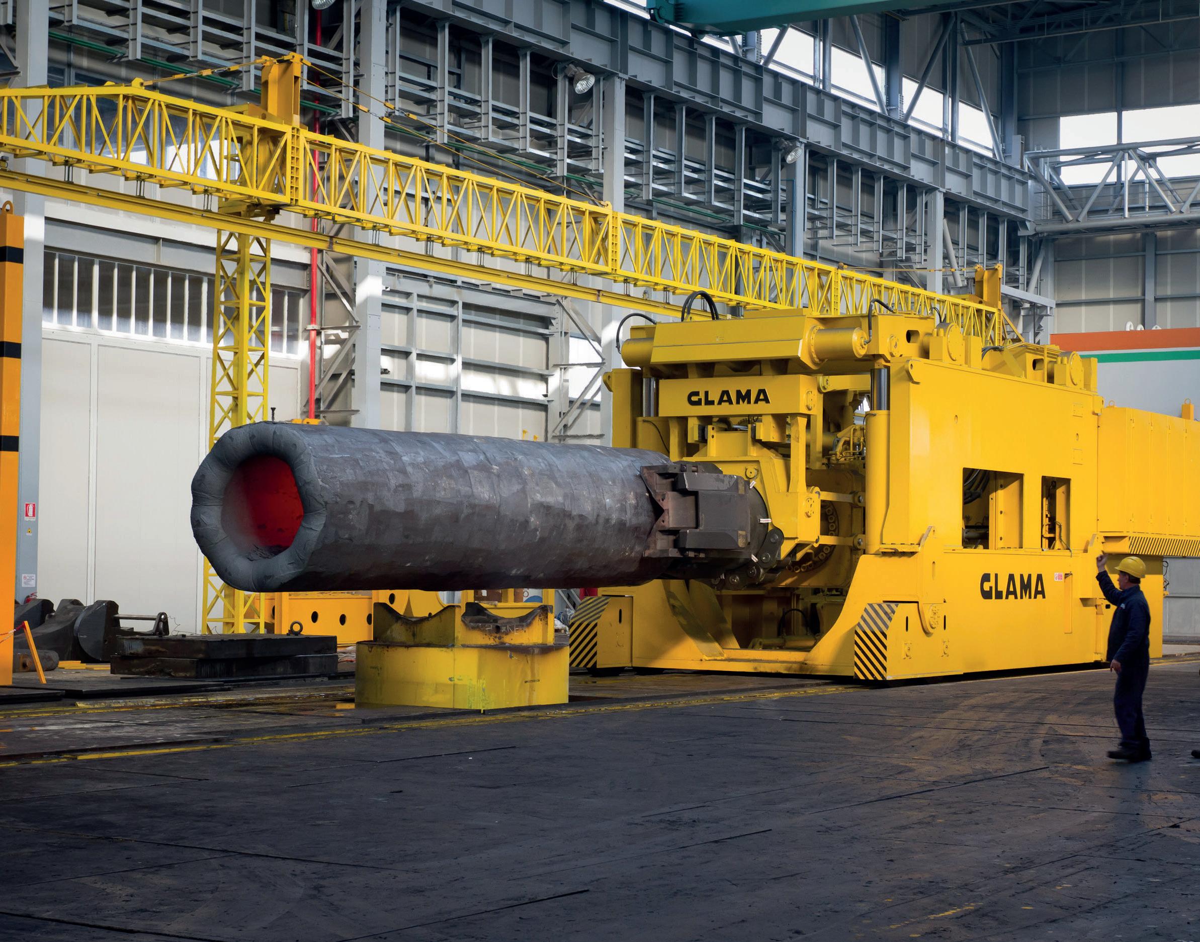

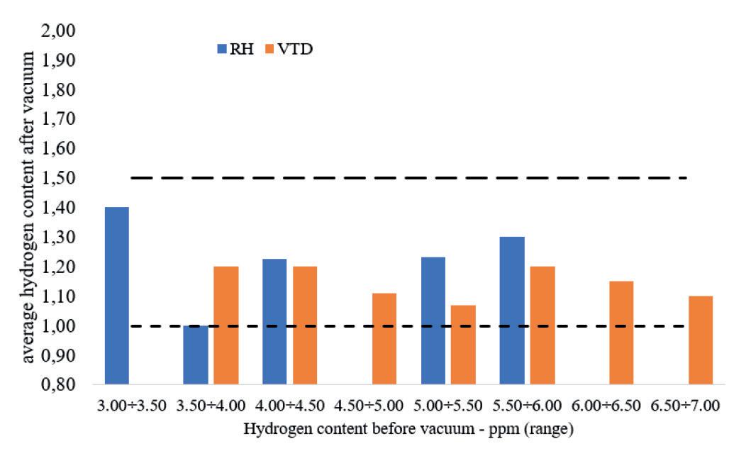
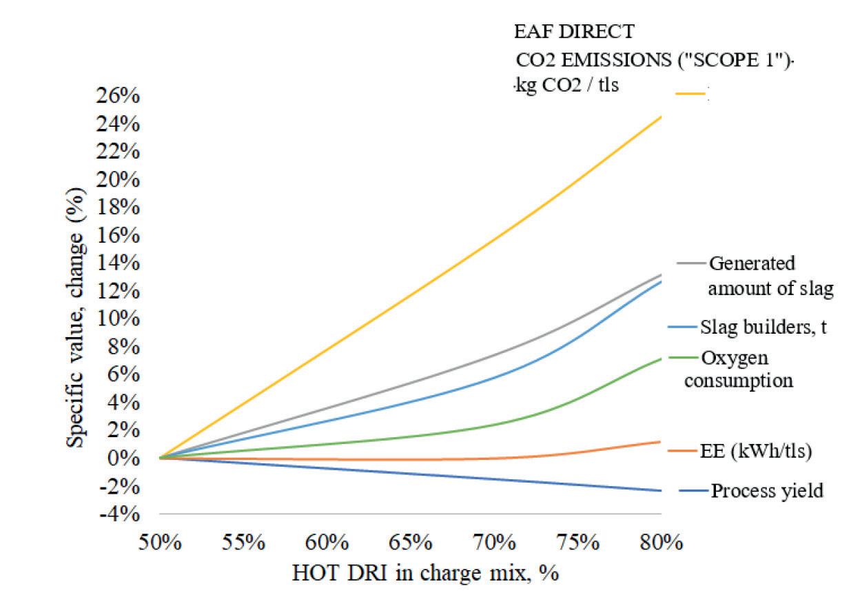
with RH and VTD as well. The chart makes clear that inlet hydrogen content is lower before the RH process compared with inlet hydrogen content for evaluated VTD grades. The main reason for lower hydrogen content in evaluated RH treated heats is that the associated steelmaking process is based on hot metal and an average 20% scrap charge (BOF process). At the same time, the evaluated results from the VTD process are based on EAF melting profiles for charges of at least 70% scrap or more.
Impact of different degassing method on EAF operation
Nitrogen content before tapping from the EAF could be in the range of 25÷100 ppm. Based on the ability to refine steel during the secondary metallurgy process (nitrogen, hydrogen, and sulphur pattern), and based on the type of EAF chosen, a proper charge mix must be evaluated for each grade of steel.
The best way to reduce nitrogen content in steel before tapping from the EAF is to apply carbon-based and clean raw materials(3). For high-quality grades, the use of direct reduced iron (DRI) pellets for EAF steelmaking is limited mainly because of the impact of splashing during the process, and these pellets are usually the source of high sulphur content.
As shown in Fig 7, the results of hot DRI in the charge mix are:
> Higher amount of CO2 emitted (scope 1 – process) is caused by higher carbon content in charge mix;
> Generated amount of slag is linked to higher amount (kg/tls) of charged nonmetallic compounds with DRI;
> Energy balance is more on the chemical than on the electrical side;
> Process yield reduction is linked with the amount of gangue content in the raw materials.
The difficulty for secondary metallurgy processes to remove nitrogen (example: RH vs. VTD) consequently makes it necessary to reduce nitrogen contents before tapping
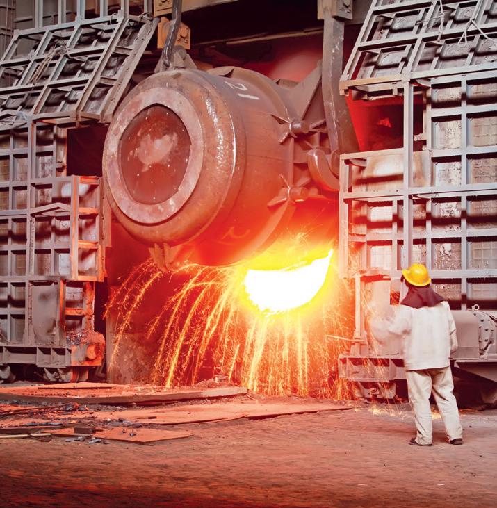
from the EAF. This is possible by increasing the amount of DRI in the EAF charge mix. Nitrogen content reduction during EAF melting has its own pros and cons. Fig 7 shows the results of simulated EAF processes for a fixed heat size, fixed tap-totap time, and with the same requirements for steel quality (same tapping temperature, same slag basicity, and same carbon and phosphorous content before tapping).
Increasing carbon-based raw material in the charge mix is common practice for high-quality steel grades (e.g., grades based on free-tapping practice followed by carbon removal under vacuum), and higher production costs during the primary steelmaking process route are usually justified by higher added-value of the final
product. Increasing EAF cost caused by reduced refining capability of secondary metallurgy shall be covered by a proper market forecast.
The choice of RH or VTD for a steel plant is determined by the steel grades to be produced.
As demonstrated, overall, VTD process wins versus RH. In fact, desulfurization by VTD reduces total LF process time, increasing overall meltshop productivity, and also improving steel cleanliness and nitrogen removal under vacuum. Furthermore, VTD allows higher flexibility in the selection of raw materials for the EAF. CapEx for VTD stations is much lower as compared to that for RH; production costs are also more competitive because of different process patterns and energy/ steam consumption.
The RH process is only recommended for ultra-low carbon, ‘non-stabilized’ grades with production rates above 20÷30%. �
B. Vucinic: “High-quality low-carbon flat grades based on EAF-LF-VD process route,” EEC 2024.
Yoshiei Kato, Tadasu Kirmara, Koji Y. Amaguchi, Tetsuya Fujii and Shigeru Ohmiya: “Air leak from the immersion tube in an RH vacuum degassing unit and the behaviour of nitrogen in steel;” Iron and Steel Vol. 83 (1997) No. 1.
R. Lule, F. Lopez, J. Espinoza, R. Torres and R.D. Morales: “The Production of Steels Applying 100% DRI for Nitrogen Removal: The Experience of ArcelorMittal Lazaro Cardenas Flat Carbon”; AISTech 2009 –Volume 1.
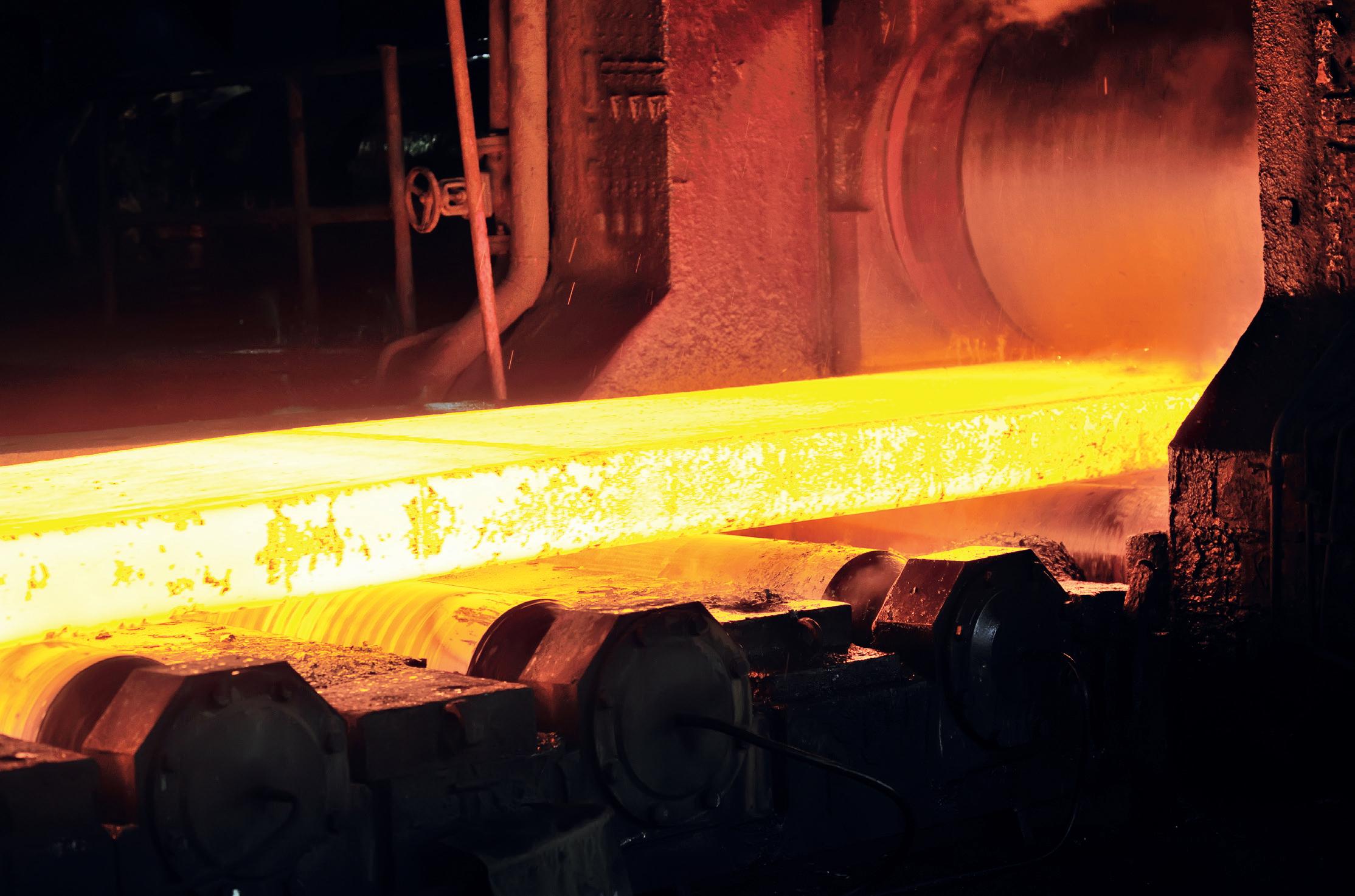
THE current most used heating source for supplying thermal energy in reheating furnaces for steel rolling mills involves combustion, which leads to the urgency of controlling greenhouse gas emissions (in particular, carbon monoxide CO, and nitrogen oxides NOx) as much as possible, to adapt the pollutants’ production to the actual and upcoming stringent global limits. Current European Best Available Techniques (abbreviated as ‘BAT’) for NOx and CO emissions related to reheating furnaces for hot rolling, are shown in Fig 1 (1) (2)
SMS group strongly commits to decarbonization in all its areas of interest, actively contributing to reducing the impact of its metallurgical plant with innovative solutions. Several pathways can be followed and are foreseen as the most promising for reducing the impact of reheating furnaces. Hydrogen’s usage as a fuel represents the cutting-edge technique in this field. Most of the SMS group’s burner solutions for reheating processes have been adapted to use hydrogen as fuel, both in ‘pure’ form and mixed with other gases (e.g. natural gas, ‘lean’ steelmaking gases), to grant a wide operational flexibility to the market. A concurrent approach can be found in oxygen usage, to modify the overall chemical composition of the comburent gas flow supply by burners: the change of ratio between nitrogen and oxygen (present respectively as 79%vol. and 21%vol. in
Umberto
‘technical standard air’) modifies the combustion process. In particular, oxygen enhances the chemical reactivity of the comburent-fuel gas system, leading to a temperature and a consequent increase of the heat release efficiency and uniformity in the furnace chamber, and a reduction of the flue gases’ volumes and fuel
consumption for comburent preheating. SMS group focused not only on adapting the existing burner technology to work with oxygen added to the air flow as comburent, but also on providing a suitable solution ready to adapt to oxygen availability in the industrial plants, which is currently a big challenge, especially in steelmaking.(3)
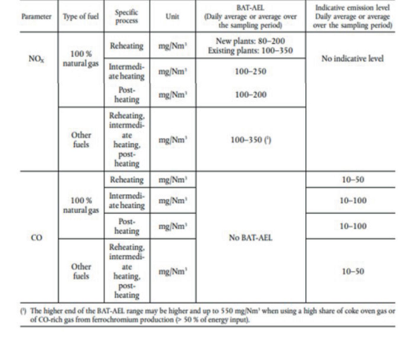
The SMS ZERO2Flame HY2 is a lateral burner designed to use a wide range of gaseous fuels and, as an oxidant, air/oxygen mixtures up to high oxygen concentrations (50%vol. O2), producing NOx emissions below 80 mg/Nm3 at 3%vol. O2 in the Dry Flue Gases (DFG). Compared to the previous version of the burner(4), the SMS ZERO2Flame HY2 exhibited improved performance in flame, flameless and booster mode, using different types of fuels and air-oxygen mixtures as comburent. In particular, the burner is modified to allow the supply of comburent flow with variable oxygen content, offering a significant flexibility to the reheating process’ needs. The burner can be fed with natural gas (abbreviated as ‘NG’), hydrogen (abbreviated as ‘H2’), coke oven gas (abbreviated as ‘COG’), blast furnace gas (abbreviated as ‘BFG’), basic oxygen furnace gas (abbreviated as ‘BOF’), pure or in any mixture.
The SMS ZERO2Flame HY2 is composed of the following components, as shown in Fig 2:
� One fuel inlet for flame mode.
� One combustion air inlet for ignition.
� One combustion air inlet.
� An air/oxygen supply system embedded in the air diffuser.
� Two fuel lateral lances for flameless mode.
Experimental tests on the SMS ZERO2Flame HY2 1 MW were carried out at the RINA CSM Experimental Combustion Studies Station, located in Dalmine (Italy). The flue gas composition was measured, and thermocouples were installed in several locations, to monitor the heat release, temperature distribution and pollutant production. The experimental rig is shown in Fig 3
The Research and development activity for the SMS ZERO2Flame HY2 consists of two main steps:
1. Modelling phase, based on CFD simulation, to define the best geometry that produces a suitable combustion process with very low NOx emissions.
2. Experimental phase, during which the prototype realized according to the results of CFD analysis is tested in an experimental furnace to verify its performance.
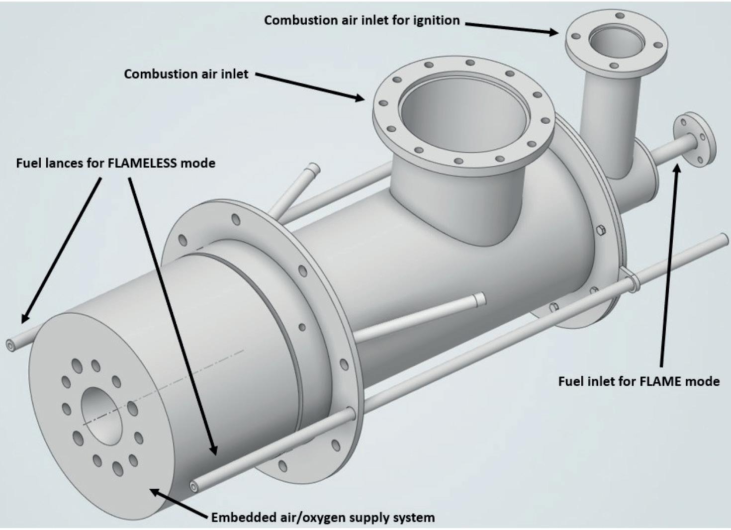
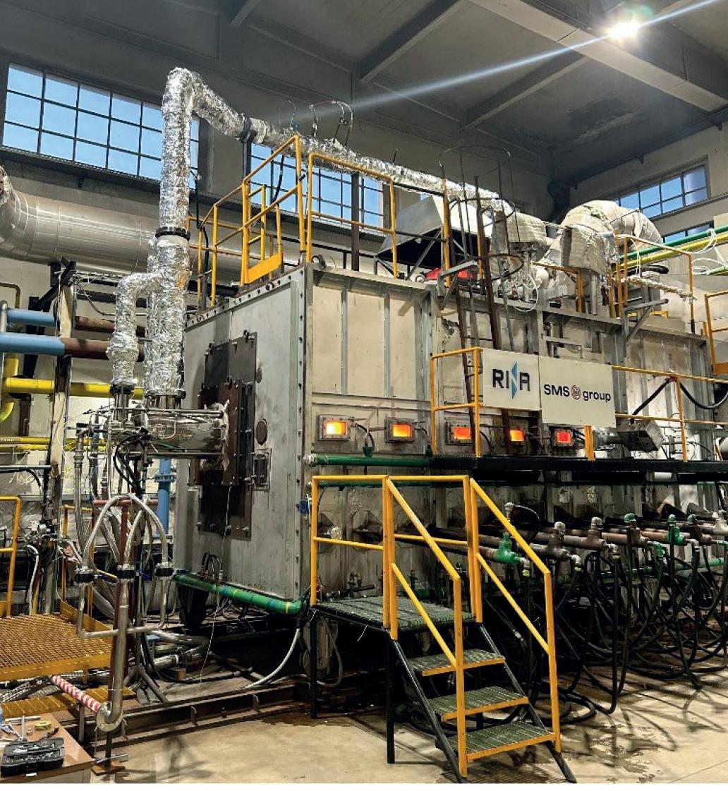
CFD activity was performed on the SMS ZERO2Flame HY2 working in flame and flameless mode, with ANSYS® Fluent®. The CFD domain used for simulating, is shown in Fig 4
This paper is focused on showing and discussing the following tested configurations, representing the most critical for NOx formation in common industrial reheating processes:
� Fuel: NG, H2, mixture NG-H2 at 50%vol. NG.
� Comburent: comburent mix up to 50%vol. of oxygen.
Noticeable differences in the calculated temperature fields can be seen in flame and flameless mode, as visible in Fig 5 for NG, with increasing the oxygen content in the comburent blend. The effect of the combustion mode and concentration of hydrogen and oxygen on the flame structure is visible from Fig 6 to Fig 8 In case of natural gas, in flame mode the flame is detached but the presence of oxygen generates a stable flame front with strong temperature gradients and a high temperature at hearth. In flameless mode there is no structured flame front and thermal gradient decreases, improving thermal uniformity in the combustion chamber. The injection of hydrogen in the fuel causes an anticipation of the reaction zone both in flame and flameless modes, and the increase of oxygen concentration enhances this effect. This is clearly visible in Fig 9 and Fig 10, in which OH- radical


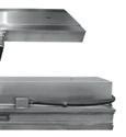
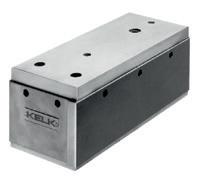


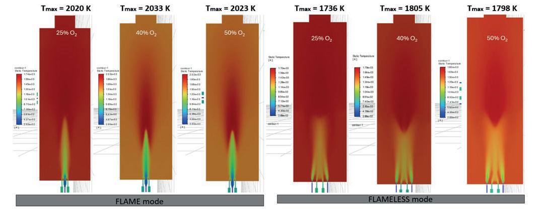
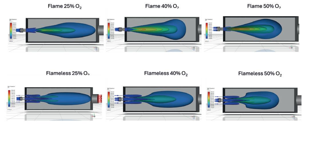
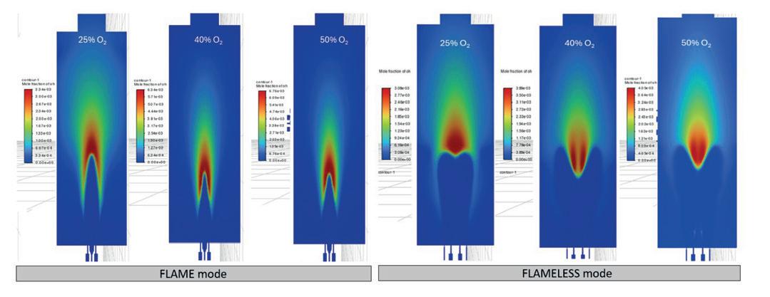
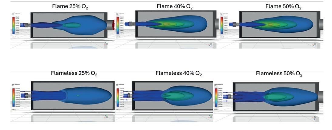
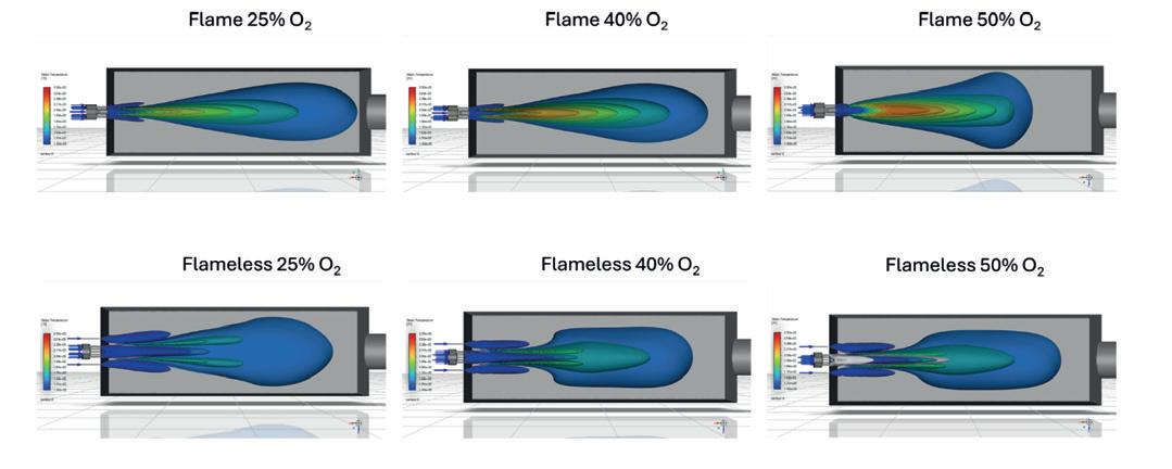
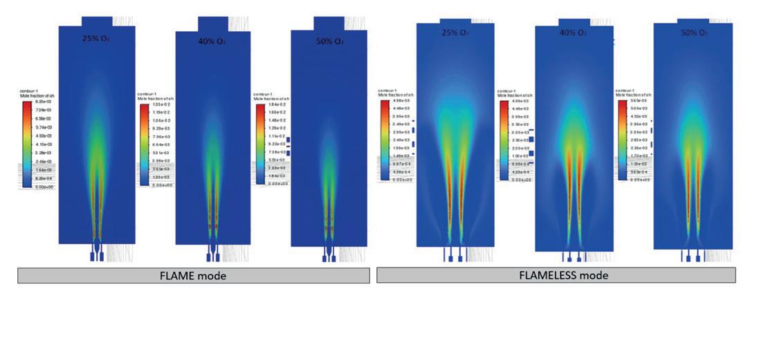
distribution in the combustion chamber is shown. The OH- radical can be considered as a ‘marker’ of the combustion process, and its distribution allows the combustion process’ characteristics to be evaluated in the combustion chamber.(5) The presence of oxygen generates a small, structured flame front. In the case of pure NG, the high oxygen concentration generates a zone with a significant concentration of OH- radicals mainly in correspondence of the central section of the furnace chamber, but the values are not sufficient to generate a stable flame front.(5) The OH- radical distributions and flame shapes are in agreement with the calculated NOx concentration at stack, visible from Fig 11 to Fig 13. The emissions with NG are very low in flameless mode but increase in flame mode as oxygen concentration increases.
If hydrogen is added to the fuel in flame mode, NOx emissions significantly increase in flame mode, up to approximately 7000 ppm in the case of pure hydrogen. It is known from previous studies on the SMS ZEROFlame burner(4) that 75%vol. H2 content in the NG- H2 fuel blend represents a threshold value for NOx emissions in flameless mode: below this value, the emission levels are kept stable and low, while beyond it the NOx production significantly increases.
The SMS ZERO2Flame HY2 1 MW burner was tested in the modular furnace of the Experimental Station for Combustion Studies of RINA-CSM, at various furnace and comburent temperatures, fuel and comburent compositions, and rating
and oxygen content rates in the flue gas. The burner was fed with natural gas and hydrogen, pure or in a mixture, and with a comburent gas flow with various oxygen content (up to 50%vol. O2).
The burner ignites at any rating, comburent/fuel ratio, fuel mixtures and cold combustion air, with the use of a pilot burner and flame detection operated by a UV sensor (above 20 µA in flame mode in all conditions).
The flame is invisible in all configurations, except for a few barely visible flickers of flame when operating with natural gas, as visible in Fig 20 and Fig 21. The combustion process exhibited no soot production, with carbon monoxide (CO) measured as 0 ppm in most of the tested conditions (less than 5 ppm only in limited specific conditions).
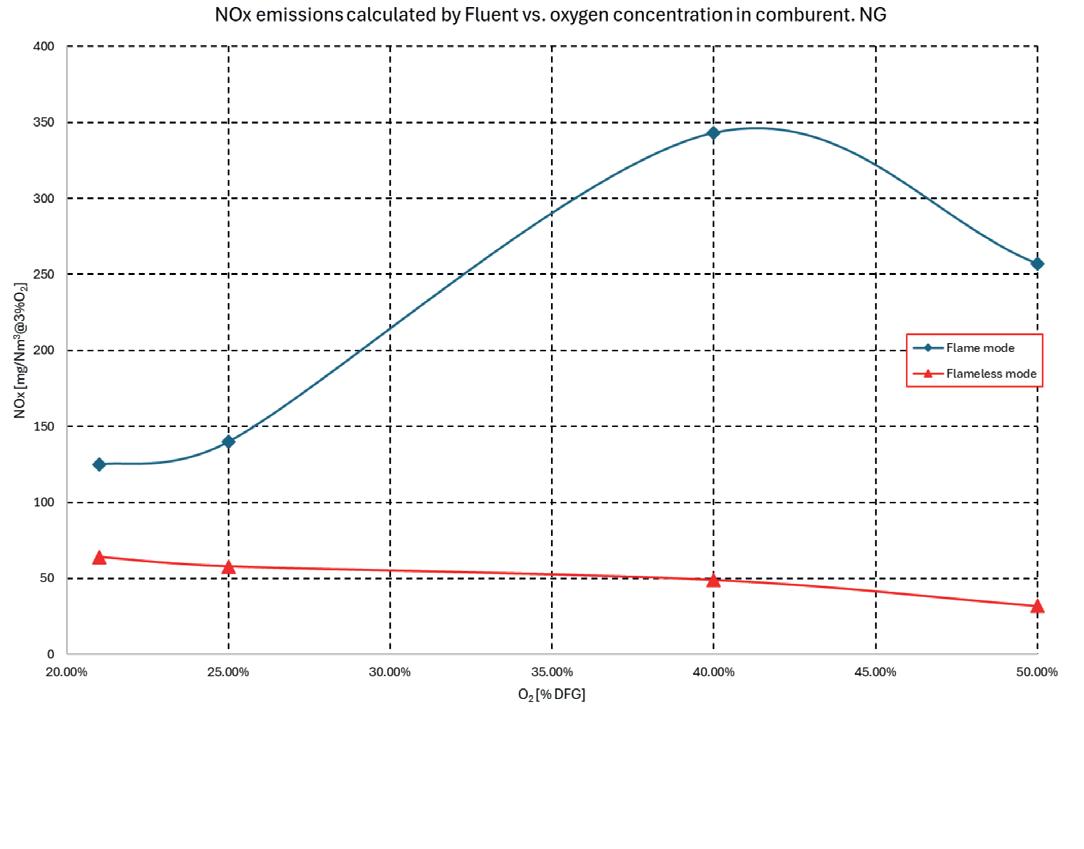
11. Calculated NOx emissions in
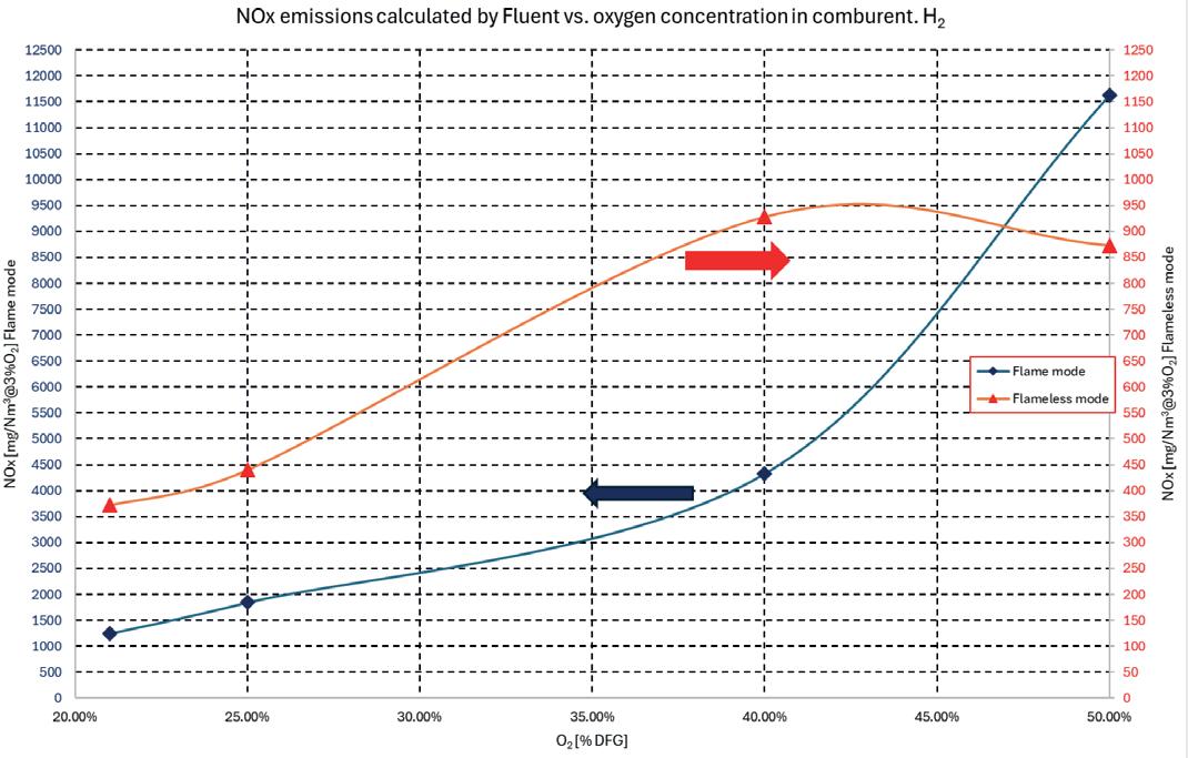
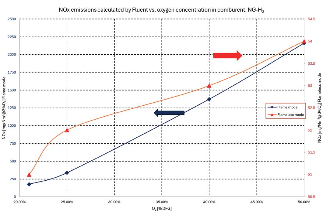
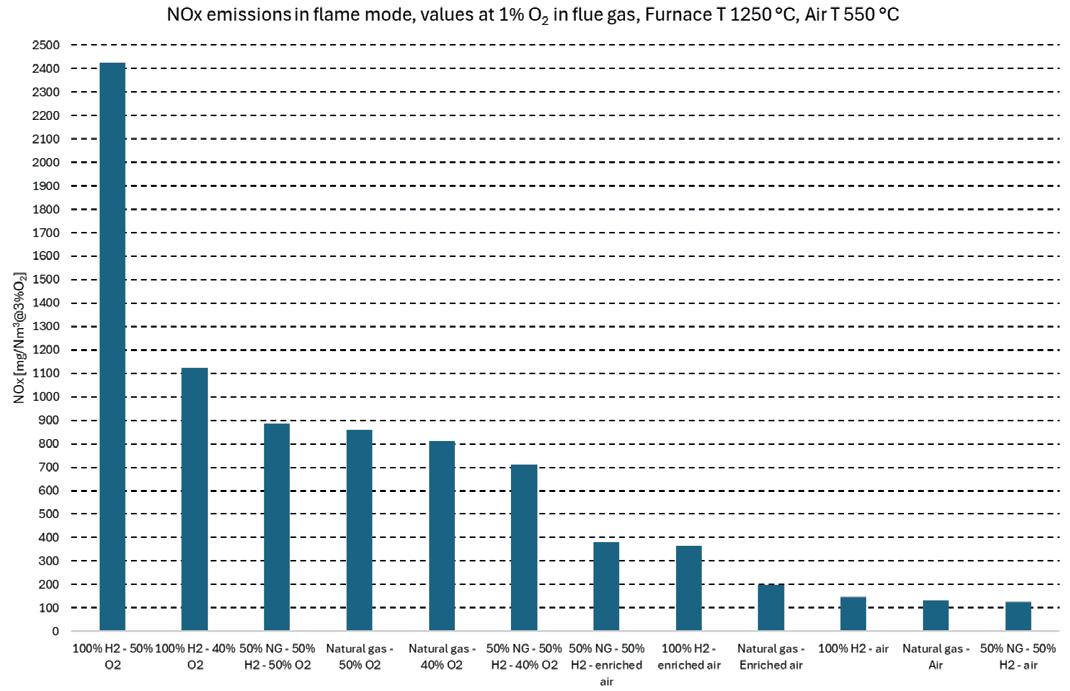
NOx emissions in flame mode are lower than 200 mg/Nm3@3%O2 only in case of 21%vol. O2 content in the comburent flow (standard technical air), otherwise the oxygen increase causes a significant increase of concentration values as visible in Fig 14, Fig 16 and Fig 18. In the case of pure hydrogen, NOx values reach 2000 mg/Nm3 at 50%vol. oxygen. Rating exhibits a limited effect on emissions, regardless of flame or flameless mode.
In flameless mode, on the contrary, NOx emissions are lower than 60 mg/ Nm3@3%O2 in all configurations, as visible in Fig 15, Fig 17 and Fig 19
4. Discussion of results
Considering the experimental results on the SMS ZERO2Flame HY2 burner, the flameless configuration reflects the characteristics of the ‘MILD’ combustion regime in the furnace chamber (meaning ‘a process in which combustion and
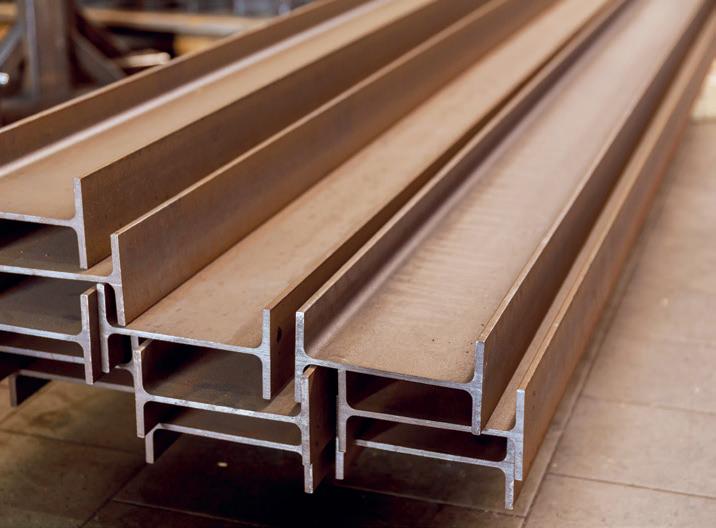
diffusion characteristic times have the same magnitude and then combustion occurs in a large volume inside the combustion chamber, with a reduced kinetic caused by the extreme dilution of reactants and consequently with low temperatures’). (6) Some discrepancies appeared between the results obtained from CFD and experimental data, especially concerning the values of NOx emissions. While in the case of NG and NG-H2 the calculated values approximate
the experimental ones with minor deviations; with pure hydrogen, the results obtained in flameless mode are significantly different from the measured ones. However, by analysing the temperature field and flames development, it is possible to find some markers that allow CFD simulations to predict the real performance of the burner. The most important parameter is the temperature distribution on the combustion chamber. For example, in the case of pure hydrogen, the maximum temperatures calculated with CFD in flameless mode are about 1850 K, which is significantly lower than with the value obtained in flame mode, that overcomes 2000 K.
The causes of the discrepancies between the results obtained from CFD and experimental data can be attributed to an improper evaluation of NOx production by the ANSYS® Fluent® post-processor in simulations where hydrogen and pure oxygen are involved. The reliability of the

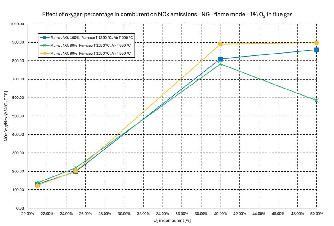
16. Effect of oxygen concentration on NOx emissions at 1% O2 in dry flue gas, gas, of the SMS ZERO2Flame HY2 working with NG in flame mode at furnace temperature of 1250 °C and comburent temperature of 550 °C
Fig17. Effect of oxygen concentration on NOx emissions at 1% O2 in dry flue gas, of the SMS ZERO2Flame HY2 working with NG in flameless mode at furnace temperature of 1250 °C and comburent temperature of 550 °C
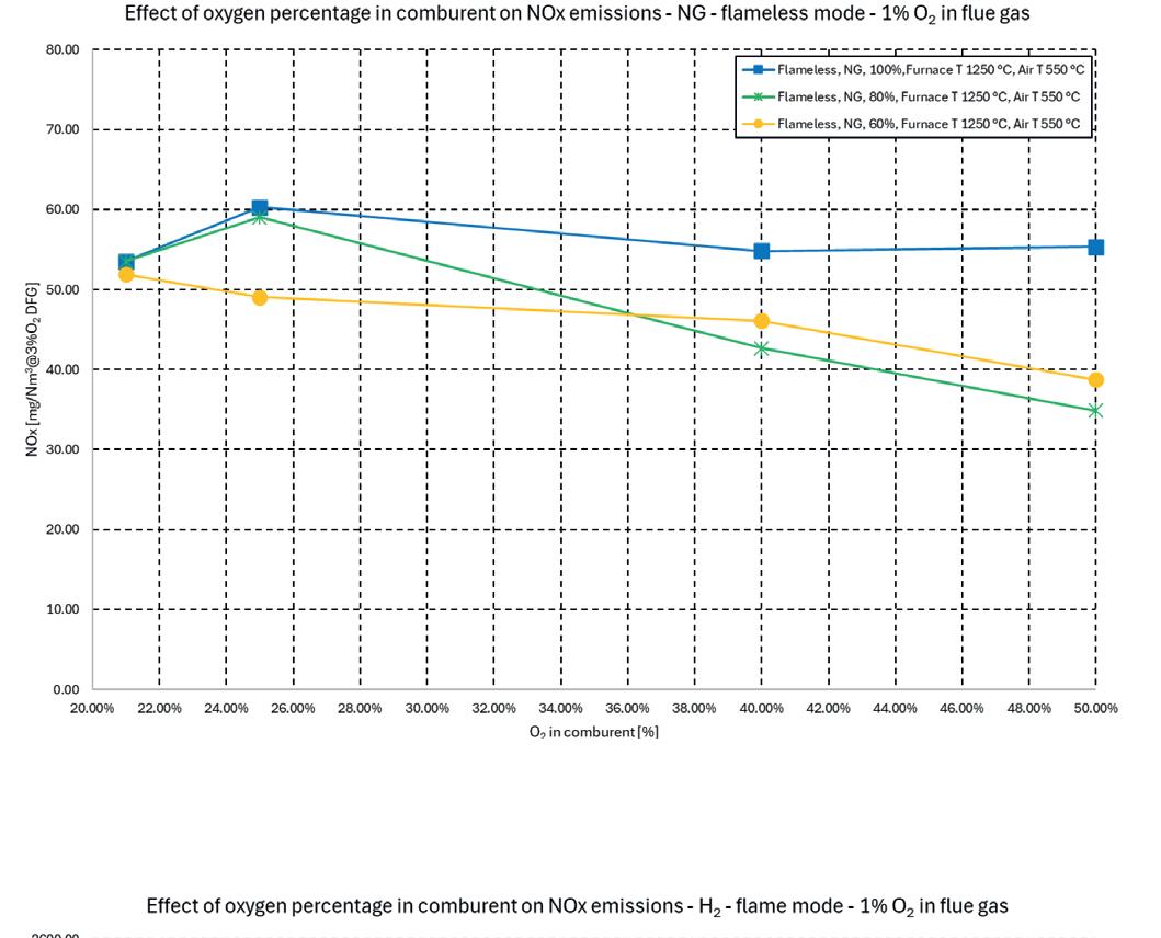
Kee-58 kinetic model in the description of the combustion process involving methane and hydrogen was investigated in literature (7). Results with a CH4-H2 fuel mixture in a MILD combustion process showed an incorrect evaluation of NOx formation likely due to the interpretation of the NNH mechanism and reburning. The error can, therefore, be attributed to an incomplete validation of the NO formation models in combustion processes involving methane, hydrogen, and high oxygen content in the comburent gas flow. The CFD simulation can be considered reliable also for NOx prediction in the case of combustion of natural gas or mixture CH4-H2 if the percentage of hydrogen is lower than 75%, otherwise only the temperature field can be considered as representative of the process The achievement of MILD combustion with high oxygen content is achieved by a strong recirculation of oxygen jets, which are shown to enhance entrainment,
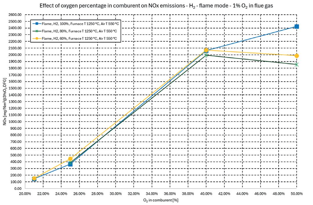
Fig 18. Effect of oxygen concentration on NOx emissions at 1% O2 in dry flue gas, gas, of the SMS ZERO2Flame HY2 working with H2 in flame mode at furnace temperature of 1250 °C and comburent temperature of 550 °C
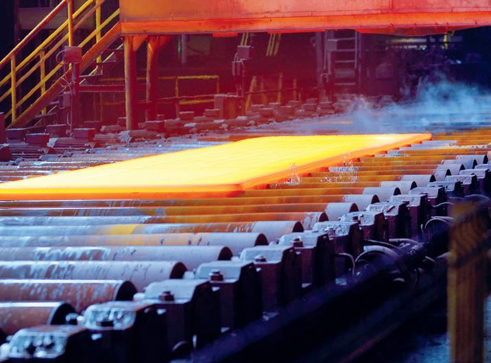
with fuel jets in a position in which oxygen concentration is lower than 9% vol. Therefore, the increase of oxygen concentration does not affect NOx emissions.
Fig 22 shows thermal profiles measured by thermocouples placed on the furnace hearth. Minimal differences can be observed between the burner operating in flame and flameless condition. The increase of oxygen concentration does not increase the
flame length, in agreement with CFD results (from Fig 6 to Fig 8), but causes a slight temperature decrease in the zone close to the burner of about 60 °C, leaving the heat release and temperature unchanged in the rest of the furnace.
The development of the SMS ZERO2Flame HY2 has produced a burner which can be used with various gaseous fuels such as natural gas and hydrogen, pure or mixed, and oxygen content in the comburent flow. The project is part of the broader research and development field of the SMS group in the area of decarbonization in the steel industry and consists of two steps: CFD modelling to find the optimal burner geometry, and experimental tests to validate the results.
Experimental tests demonstrated that in the flameless mode, NOx emissions are lower than 60 mg/Nm3@3%O2 DFG
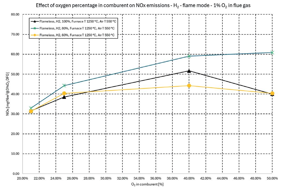
Fig 19. Effect of oxygen concentration on NOx emissions at 1% O2 in dry flue gas, gas, of the SMS ZERO2Flame HY2 working with H2 in flameless mode at furnace temperature of 1250 °C and comburent temperature of 550 °C .
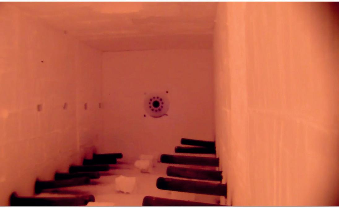

Fig 20. Video-monitoring of the SMS ZERO2Flame HY2 working with H2 (50%vol. O2 content in the comburent) in flame mode at furnace temperature of 1250 °C and comburent temperature of 550 °C.
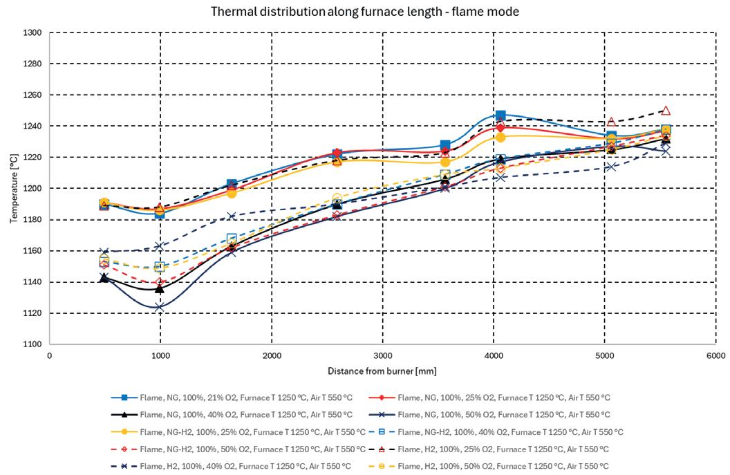
Fig 22. Temperature distribution measured inside combustion chamber, of the SMS ZERO2Flame HY2 working with different fuels at furnace temperature of 1250 °C and comburent temperature of 550 °C.
with a furnace temperature of 1250 °C and a preheating comburent temperature of 550°C, while the values increased significantly in flame mode.
The results have been achieved by increasing the dilution of the oxidant and fuel jets by optimizing the nozzle geometry, so that the reagent gas streams only meet after reducing the concentration of the reactants to extremely low values. This extreme dilution decreases reaction kinetic and enables a MILD combustion process. �
6. References
1. Aries, E., Gómez, Benavides, J., Mavromatis, S., Klein, G. Best Available Technique (BAT) Reference Document for the Ferrous Metals Processing Industry Industrial Emissions Directive 2010/75/EU (Integrated Pollution Prevention and Control). Luxembourg : Pubblication Office of the European Union, 2022.
2. European Union. COMMISSION IMPLEMENTING
DECISION (EU) 2022/2110. Best available techniques (BAT) conclusions, under Directive 2010/75/EU of the European Parliament and of the Council on industrial emissions, for the ferrous metals processing industry. s.l. : European Union, October 2022.
3. A two-stage method for predicting and scheduling energy in an oxygen/nitrogen system of the steel industry. Zhongyang, Han, et al. July 2016, Pages 35-45, s.l. : Control Engineering Practice, Vol. 52.
4. Development and testing of flameless burner fed by NG/H2 mix. U. Zanusso, J. Fabro, I. Luzzo, F. Cirilli. 3- 4, 2021, Matériaux & Techniques, Vol. 109.
5. Laseroptical investigation of highly preheated combustion with strong exhaust gas recirculation. Plessing, Tobias, Peters, Norbert and Wünning, Joachim G. 1998, Symposium (International) on Combustion, pp. 3197-3204.
6. Mild Combustion. Cavaliere, Antonio and de Joannon, Mara. 4, Pages 329-366, s.l. : Progress in Energy and Combustion Science, 2004, Vol. 30.
7. A simplified approach for predicting NO formation in MILD combustion of CH4-H2 mixtures. Parente A., Galletti C., Tognotti L. s.l. : The Combustion Institute,
2011. Proceedings of the Combustion Institute. Vol. 33, pp. 3343-3350.
8. Kanury, A. M. Introduction to combustion phenomena. New York : Gordon and Breach, 1975.
9. European Commission. The European Green Deal. The European Green Deal – COMMUNICATION FROM THE COMMISSION. Brussels, Belgium : The European Union, 11 12 2019.
10. Burners in the steel industry: utilization of byproduct combustion gases in reheating furnaces and annealing lines. Caillat, Sébastien. 2017, Energy Procedia, pp. 20-27.
11. Baukal, Charles E. Jr. Introduction. Oxygen-enhanced Combustion. Boca Raton : CRC Press, 2013.
12. On reduced mechanisms for methane air combustion in nonpremixed flames. Bilger, R.W. , Stårner, S.H. and Kee, R.J. . 1990, Combustion and Flame, pp. 135-149.
13. A Numerical Study of a Bluff-Body Stabilized Diffusion Flame. Part 2. Influence of Combustion Modeling And Finite-Rate Chemistry. Gran, Inge R. and Magnussen, Bjørn F. 1-6, Pages 191-217, s.l. : Combustion Science and Technology, 1996, Vol. 119.


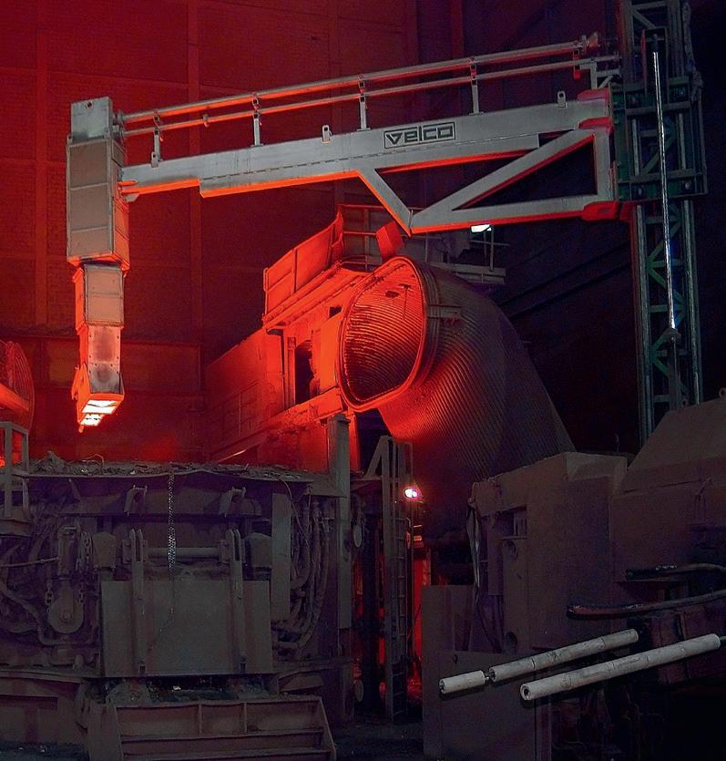
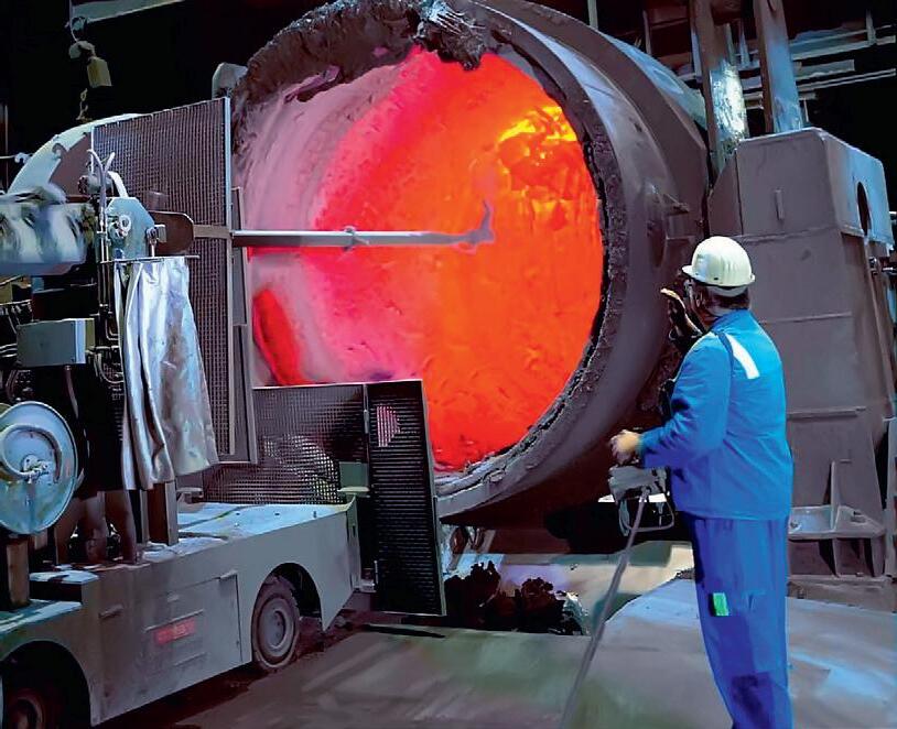
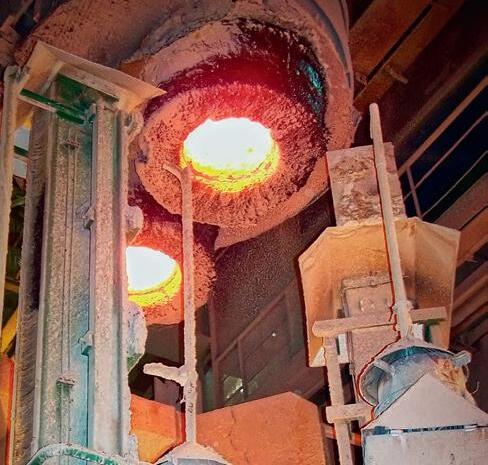


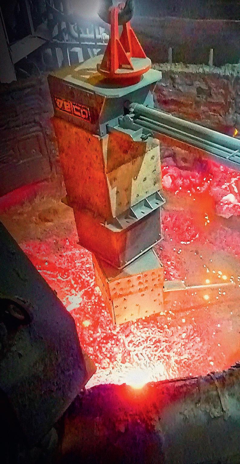


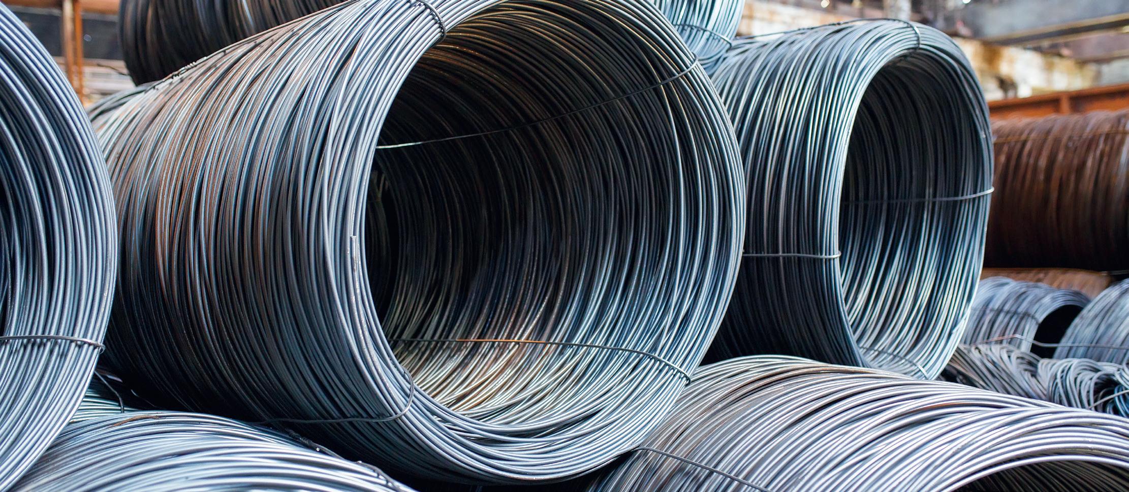
This article describes some applications developed as part of the Lighthouse Project – Acciaio 4.0, implemented by Tenova and ORI Martin, a digital transformation initiative aimed at developing a fully interconnected, energy-efficient, and environmentally sustainable steel plant by leveraging advanced automation, artificial intelligence, and IoT technologies. The project was financed by the Italian Ministry of Economic Development (MISE) and recognized as one of Italy’s Lighthouse Plants by the Cluster Fabbrica Intelligente (CFI), which promotes cutting-edge industrial innovation projects. By Giovanni Bavestrelli*, Enrico Malfa**, and Maurizio Zanforlin***
IN electric arc furnaces (EAFs), metallic raw materials (ferrous scrap) contribute to more than 60% of the total production costs. The EU-27 Steel Scrap Specification classifies the scrap categories (qualities) by their origin, shape, and content in residual elements. These different grades of steel scrap are combined to produce the targeted carbon steel quality (scrap mix). EUROFER has estimated that scrap will play an increasingly important role in the EU steel strategy for the reduction of CO2 emissions (Fig 1).
In this scenario, scrap characteristics are expected to drastically change and deteriorate due to repeated recycling, the recycling rate (steel is a permanent material) and the consequent heterogeneity of available ferrous material (e.g., the combination of steel with plastics and fibres, more complex joints, technical coatings, etc.). Scrap availability as well as cost and quality factors require implementing actions focused not only on the scrap market but also on optimal charge preparation and improved process control. To guarantee a reliable performance, it is necessary to assess the influence of scrap quality on the final product.
Dynamic and robust charge mix optimization tools have been applied in the industry to determine the optimal charge mix for each individual steel grade with
respect to quality restrictions of the crude steel as well as the availability, purchasing costs, yield, and meltdown energy demands of individual scrap types.
Today, digital systems and tools can be applied to support scrap yard management activities, including scrap yard inventory systems, which track the availability of charge materials in the scrap yard. The inventory database must be automatically updated every time a scrap delivery enters the plant, and every time a scrap material has been loaded and charged to the furnace.
I. Ori Martin steel plant
The Ori Martin steel plant, in Brescia, Italy, produces wire rods and round bars by recycling metal scrap material. Every day, approximately 100 trucks containing various types of steel scrap enter the plant, each truck carrying between 15 and 30 tons of metal scrap. This scrap is used to feed an EAF, which melts the scrap into liquid steel by heating it up to a temperature of approximately 1660 to 1680 C°, about 25 to 30 times a day (each operation is called a ‘heat’), producing approximately 90 tons of steel per heat.
The furnace uses several types of scrap materials which are combined to create a variety of products, mainly for the automotive, mechanics, energy, and construction sectors. To control the
characteristics and quality of the product, it is important that the scrap material is classified and tracked accurately from the time it enters the plant to the time it exits the EAF as molten steel. This article presents solutions developed by Tenova that are aimed at improving the classification, tracking, and mixing of the steel scrap, from truck entrance to liquid steel tapping. When implemented, the technologies improve the profitability of EAFs and the quality of their final products, thus they have become an integral part of Tenova’s product portfolio.
Machine learning models need data.
To gather data from customer plants worldwide, Tenova has developed an IoT Platform based on Microsoft Azure. This cloud platform can receive data from multiple plants, process it and store it in appropriate locations. By using the data for machine learning models and for interactive dashboards at Tenova offices and/or at customer sites, the platform provides customers with KPIs indicating the performance, health, and maintenance status of the equipment.
Tenova’s customers from the steel industry are typically reluctant to allow an internet connection from their plants to the cloud and would not accept the correct operation of their plants to require a
*Data science director Tenova S.p.A (giovanni.bavestrelli@tenova.com) ** R&D director Tenova S.p.A (enrico.malfa@tenova.com) ***R&D manager Ori Martin S.p.A (maurizio.zanforlin@orimartin.it).
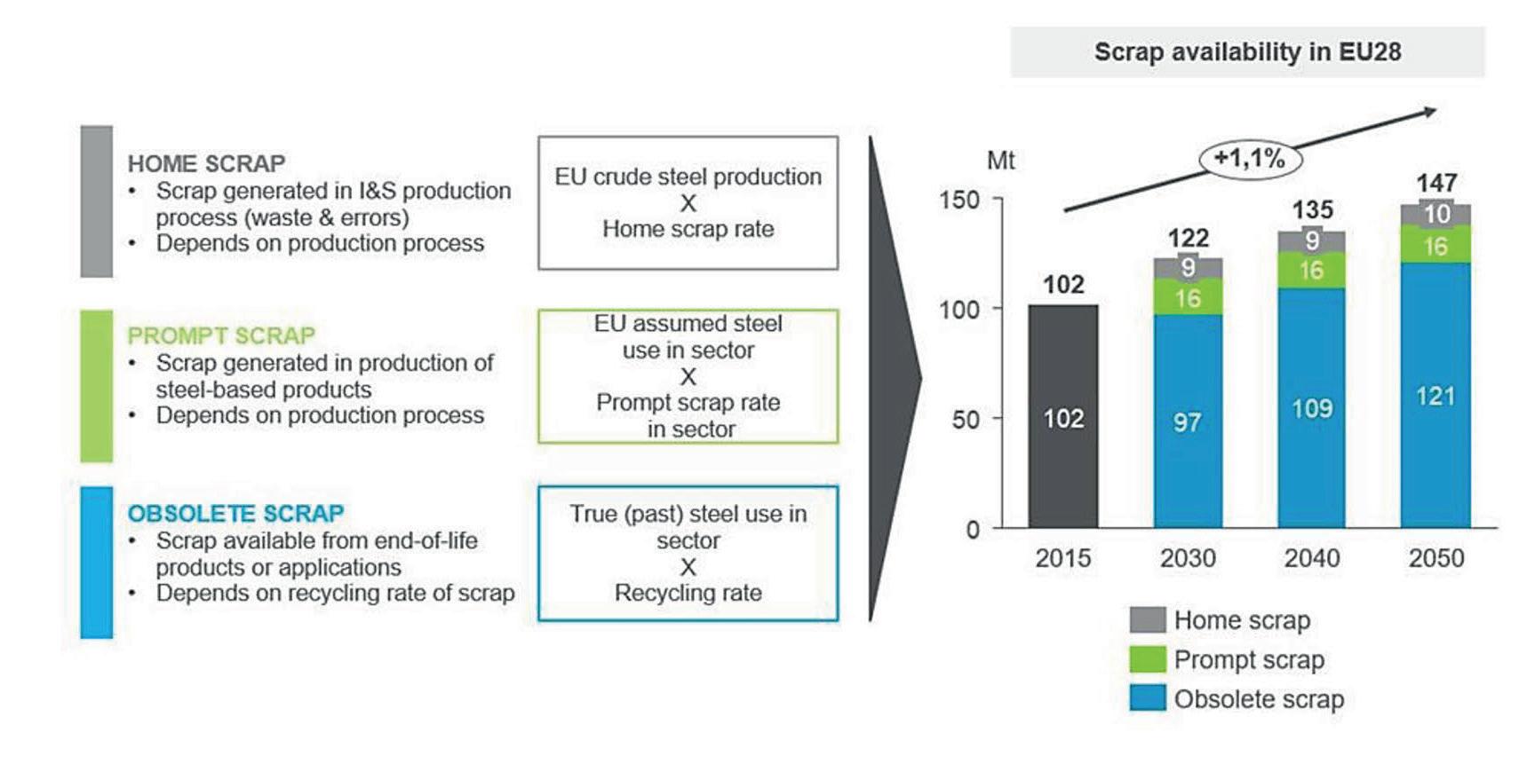
functioning internet connection. Moreover, the models would need to respond in near real-time. Therefore, even where an internet connection is available, as at Ori Martin, the models are nevertheless deployed onpremises.
To meet these requirements, Tenova has developed Tenova EDGE, an edge device comprising a local computer that implements a microservices architecture based on Microsoft IoT Edge, with dedicated software developed by Tenova. This device is used to read data from plants and send it to the cloud as well as an environment to deploy models built and trained in the cloud and run them on the premises. The models are deployed inside Docker containers on the Tenova EDGE device in the plant. The communication with plant automation is based on RabbitMQ, an open-source message broker.
When a truck enters the plant, it is weighed, scanned for radioactivity, and a picture is taken of its load. The load is then discharged in the scrap yard and inspected to confirm type and quality, ensuring it matches what was expected from the purchase order. This is a manual operation involving skilled technicians.
The furnace typically operates using nine major types of scrap material, as shown in Fig 2
Over the course of the project, more than 100,000 images of trucks entering the plant were gathered and stored on the cloud. The image ‘labels’ (i.e., their target classes) were taken from a database already present at the plant, as each purchase order had already been checked and tracked. Some of these images were used to train machine learning models, using Convolutional
Neural Networks (CNN) to automate the classification of the scrap material as an aid to technicians by highlighting possible mismatches.
We spent a long time analyzing the images, selecting good quality ones, verifying the labels, and deciding what to do in cases where it was impossible to detect the content of the truck, for example when the truck was covered or when it was not placed correctly under the camera.Fig 2
Once we had a good dataset consisting of 11 categories (nine types of scrap, plus ‘misplaced’ and ‘covered’ trucks), with around 1,000 good images per category (except for the covered trucks, of which we had much fewer images), we separated the images into training, validation and test sets. We trained several different convolutional neural networks
with different hyperparameters to classify these images, selecting the ones yielding the best accuracy on the validation set. We then tested its accuracy on the test set, as is standard practice in image classification projects.
The accuracy achieved on the 11 categories was around 85%. The main challenge was the difficulty of the model to differentiate between the three types of metal sheet, and between the two types of turning. However, considering the three metal sheet categories as one and the two turnings as one since they were treated the same in production, the accuracy on the resulting eight categories went up to approximately 95%.
The model is deployed on the Tenova EDGE device inside the Ori Martin plant. When a truck enters the plant, a picture is taken, sent to the model, classified, and the response is sent to the technician’s tablet, so the technician is advised about the type of material expected in the purchase order and the type classified by the model. They can then make their decision.
The model does not classify all the material in the truck, given it is based on an image of the load from the top, when there could be different material below the surface that is not visible until the material is unloaded. Currently, this is not critical as the model is only used to advise operators, who also observe the material once it is unloaded on the ground. Nevertheless, we have added another classification model on the Consteel®, Tenova’s continuous
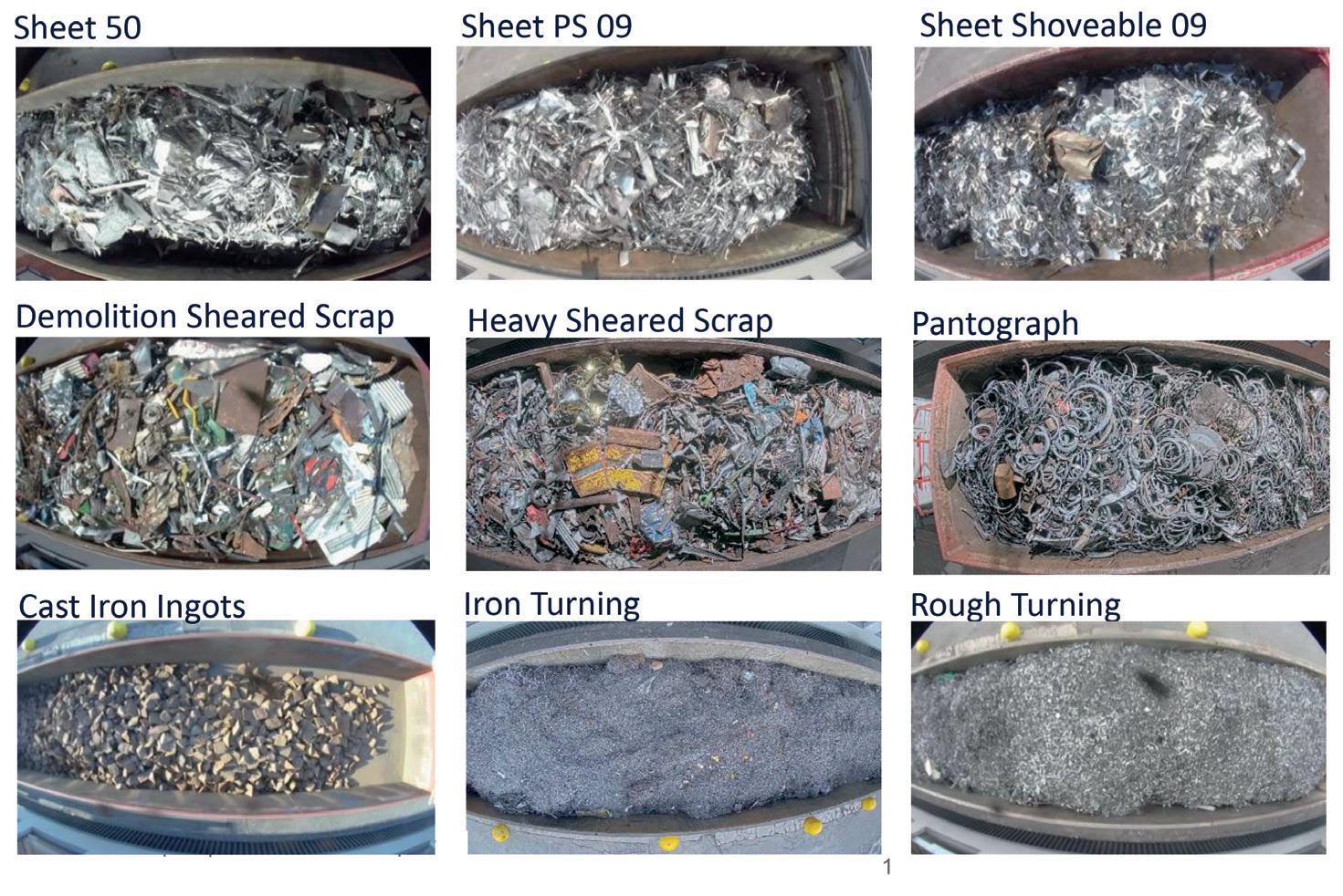

Can you imagine a greener future for the metals industry? We can. We design, develop and achieve it every day.
At Tenova, we partner with our stakeholders to design and develop solutions for metal processing that cut costs, save energy, decarbonize production processes and reduce environmental impact.
From hydrometallurgy and pyrometallurgy to material handling, DRI to EAF, from reheating and heat treatment furnaces to cold mills, processing lines and roll grinders, we offer premium technologies that are the result of responsible, reliable, environmentally-friendly innovation.
With over two thousand employees across five continents, we are present wherever our clients need us, ready to create together sustainable solutions that are tailored directly to their needs.
scrap charging system, just before the scrap material enters the EAF furnace, to get further information about what exactly enters the furnace.
The Ori Martin plant uses Tenova’s Consteel® to load the EAF. The Consteel® system continuously feeds and pre-heats the metallic charge (scrap, pig iron, etc.) to the EAF, while simultaneously controlling gaseous emissions.
The charge is loaded directly from the scrap yard to the charge conveyor, where it is automatically and continuously preheated and conveyed to the EAF. Once preheated, the charge falls into the EAF where it is melted by the liquid steel. This allows constant flat bath operation, a key advantage over conventional batch processes where scrap is melted directly by the electric arc. If the scrap material on the conveyor is bulky and heavy, it might risk hitting and damaging the electrodes when falling into the furnace. To prevent this, Tenova has developed a machine learning solution aimed at identifying such material on the Consteel® conveyor, giving operators a chance to lift the electrodes before the material enters the furnace.
The first task was deciding what type of materials were to be considered as bulky and dangerous and, therefore, should be identified in advance. Following discussions with the plant technicians, we concluded that the two most common types of dangerous materials that could end up on the Consteel® were large metal sheets and wire rods (Fig 3 and Fig 4).
We placed a camera above the Consteel® conveyor at the start of the project. The camera quickly gathered hundreds of thousands of images, with one image for each 1-metre advance of the scrap; the scrap moves at a speed of approximately 1 metre every 10 seconds, so one image is taken every 10 seconds when the Consteel® works normally. The problem was that none of these images were labelled so we did not know which images contained wire rods or metal sheets, and such materials were relatively rare. For a human to scan hundreds of thousands of images looking for wire rods or metal sheets would have been a frustrating, time consuming and error-prone job.
To solve this issue, we downloaded over 100,000 images and used an open-source
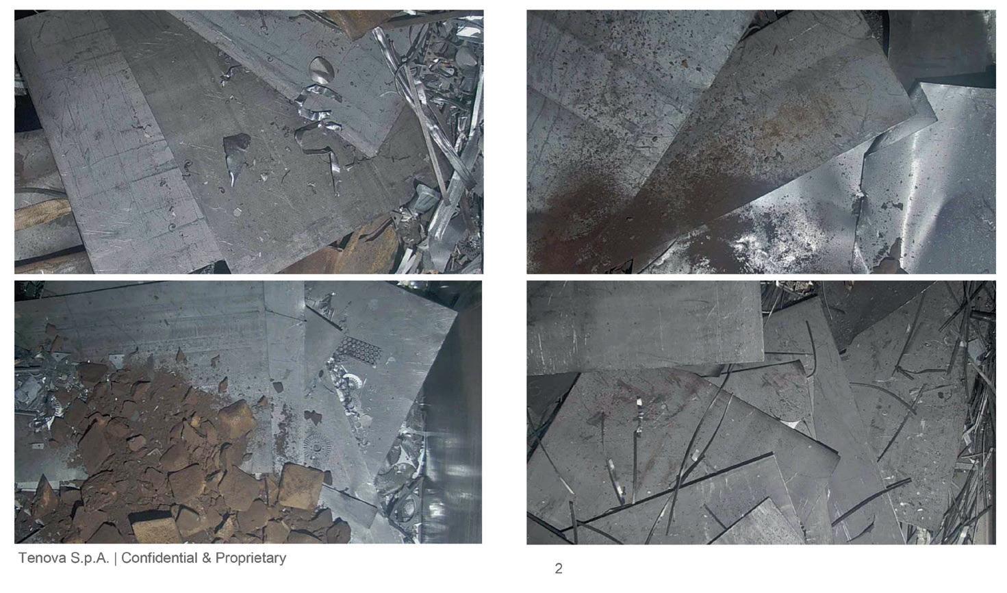
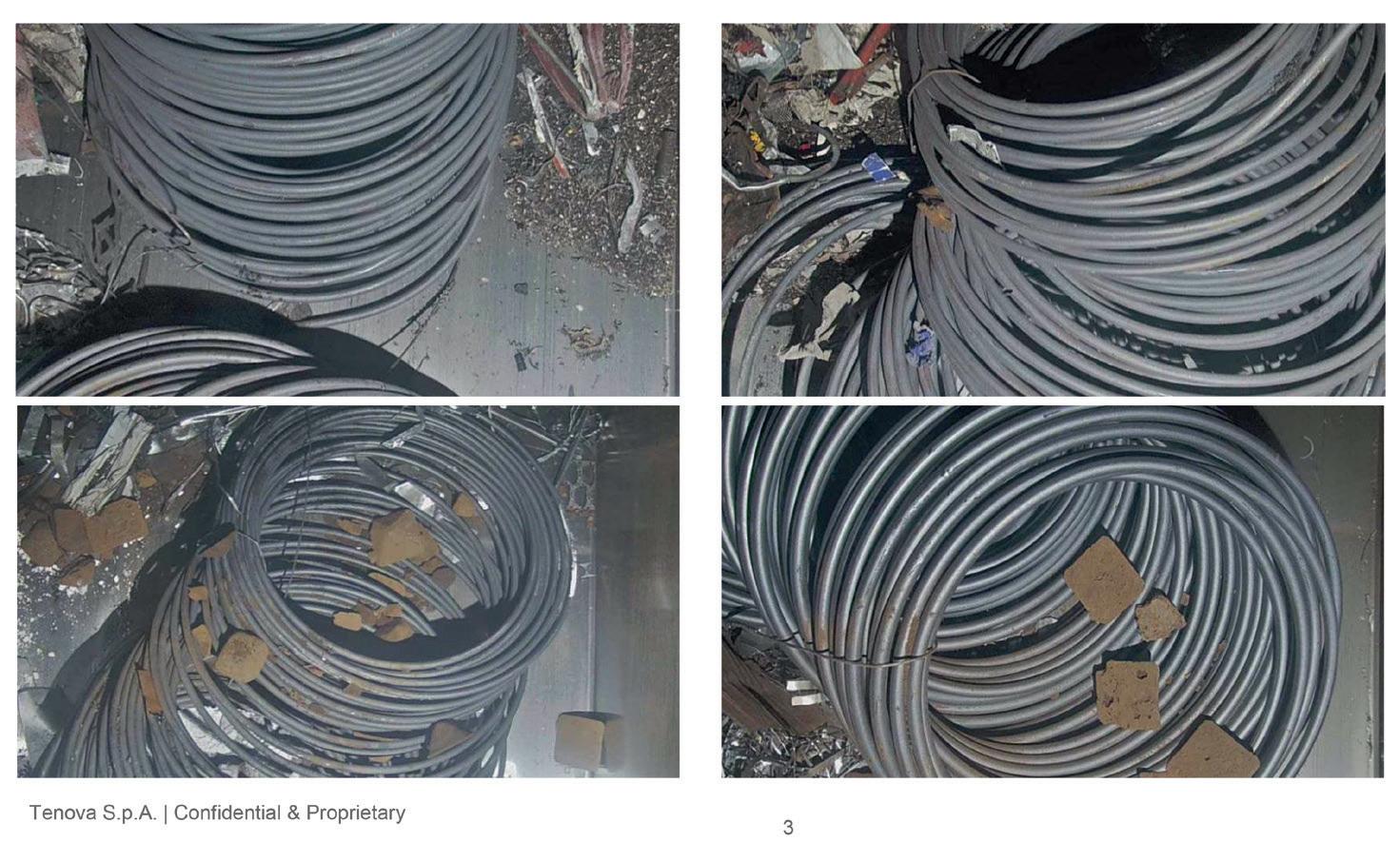
pre-trained convolutional neural network (ResNet50) to extract features from all images. We then used a sample image of a wire rod and sorted all images in order of their similarity to the sample image. From just one image of a wire rod, we were quickly able to identify hundreds of images of wire rods. By repeating the process with different sample images, we identified even more wire rods.
We used the same process for metal sheet images. At this stage, we had a reasonably sized, balanced dataset of three categories of images: wire rods, metal sheet, and everything else. We divided them into training, validation, and test sets, and trained several convolutional neural networks with different hyperparameters, selecting the best performing ones on the validation set, and measuring their
accuracy on the test set. We only used transfer learning designing on our models on top of pretrained open-source models (ResNet50) as we saw it had worked well in the classification of scrap material on trucks. The results were reasonably good. We then looked at the misclassified images one by one – always a useful exercise when evaluating the performance of an image classification algorithm, more so than just looking at percentage accuracy. Working on the dataset, removing images that were bad quality or not clear, making sure it was clean and contained good representative images improved the predictions more than trying different models and fiddling with their hyperparameters.
At this point we had close to 1,000 representative images of each of the three categories. We trained the models again
measuring their performance, which was above 95% on the test set made up of 300 images. We integrated the model with the furnace control system and deployed it into production on the Tenova EDGE device, monitoring its performance, and it initially worked smoothly: it warned operators when bulky material was on the Consteel®, giving them an opportunity to observe them and decide if the electrodes should be raised to avoid damage. However, it incurred an error, warning of bulky materials when the Consteel® was empty.
This was a serious ‘false positive’ error, as it is normal for the Consteel® to be empty at times, certainly not a dangerous event. We soon identified that the error was triggered by the bottom of the Consteel , which is made of metal sheet (Fig 5), and therefore classified as metal sheet, considered bulky and possibly dangerous by the model.
To solve this problem, we created a new category of images, representing ‘Empty’ Consteel®. We searched the dataset for several images of empty Consteel, selected the best images one by one, and retrained the model with the four categories. This model has been in in production for over two years. The accuracy of the predictions is now above 95%. The model is integrated with the furnace control system and warns operators when bulky material is present.
V. Finding correlation between loaded scrap material and tramp elements in liquid steel
To be able to control the quality of an electric arc furnace production, it is very important to track the scrap material going into each heat and relate it to the quality of the liquid steel produced. In other words, we need to know accurately what scrap material was used and relate it to the chemical analysis of the liquid steel. To do this, we developed an application using a laser scanner to track the volumes of scrap material stocked in each area of the scrap yard and adopted a new weighing algorithm on the crane that can weigh the load with a maximum error of 2% while the crane is in motion. This required advanced mathematical modeling given the complexity of weighing a crane’s load in motion. Once the scrap load is melted in the furnace, the next necessary step is measuring the quality of the final product. To this end, as part of the production process at Ori Martin, a chemical analysis of the liquid steel is always performed after

each heat.
Some chemical elements that are present in the scrap material are considered ‘tramp’ elements (pollutants). Particularly critical tramp elements are those that remain in the liquid steel, and do not get oxidized away nor end up in the slag. Since their levels in the liquid steel are an important indicator of the quality of steel, such levels must be controlled. To achieve the final steel composition required in the cast product, the quantity of such elements needs to be controlled in the raw materials as well. Some of the key elements are Copper (Cu), Nickel (Ni), Arsenic (As), Tin (Sn) and Molybdenum (Mo).
The goal was to use machine learning to find the correlation between the combination of supplier and scrap material type, and the average percentage of each tramp element in the supplied scrap.
We had data relative to over 9000 heats, we knew the total weight of each scrap material that went into the furnace, because we tracked every single loading operation by the crane, and we also knew the chemical analysis of the resulting liquid steel, which included the percentages of the five tramp elements mentioned above.
Since the tramp elements remained in the liquid steel, we could use a linear regression model without an intercept term to find the coefficients (percentages) of copper, nickel, arsenic, tin and molybdenum present in the scrap for each combination of supplier and material.
There were 11 different scrap materials and 33 different suppliers, for a total of 81 combinations of material and suppliers. Not all combinations of material and suppliers were frequent enough to be used reliably in a regression model, so all heats containing rare combinations were removed from the dataset.
A lot of work went into creating the dataset, introducing new features representing physical quantities that were important in the process, cleaning the data, identifying outliers, taking into consideration the liquid heel that remains in the furnace from each previous heat, and whose contribution to the tramp elements should be accurately calculated.
We trained a linear regression model to estimate the level of each tramp element present in each material provided by each supplier. Naturally, this was a statistical value, not a measure of the content of the tramp element in the material, but this was enough to allow an assessment of each supplier and to get a reasonable prediction of the level of each tramp element in a heat given the combination of scrap in the mix.
Having used linear regression to calculate the percentages, a good measure to evaluate the quality of the results was to calculate the coefficient of determination, R2, which indicates the proportion of the variation in the percentages of tramp elements in the liquid steel that is predictable from the scrap material loaded in the furnace.
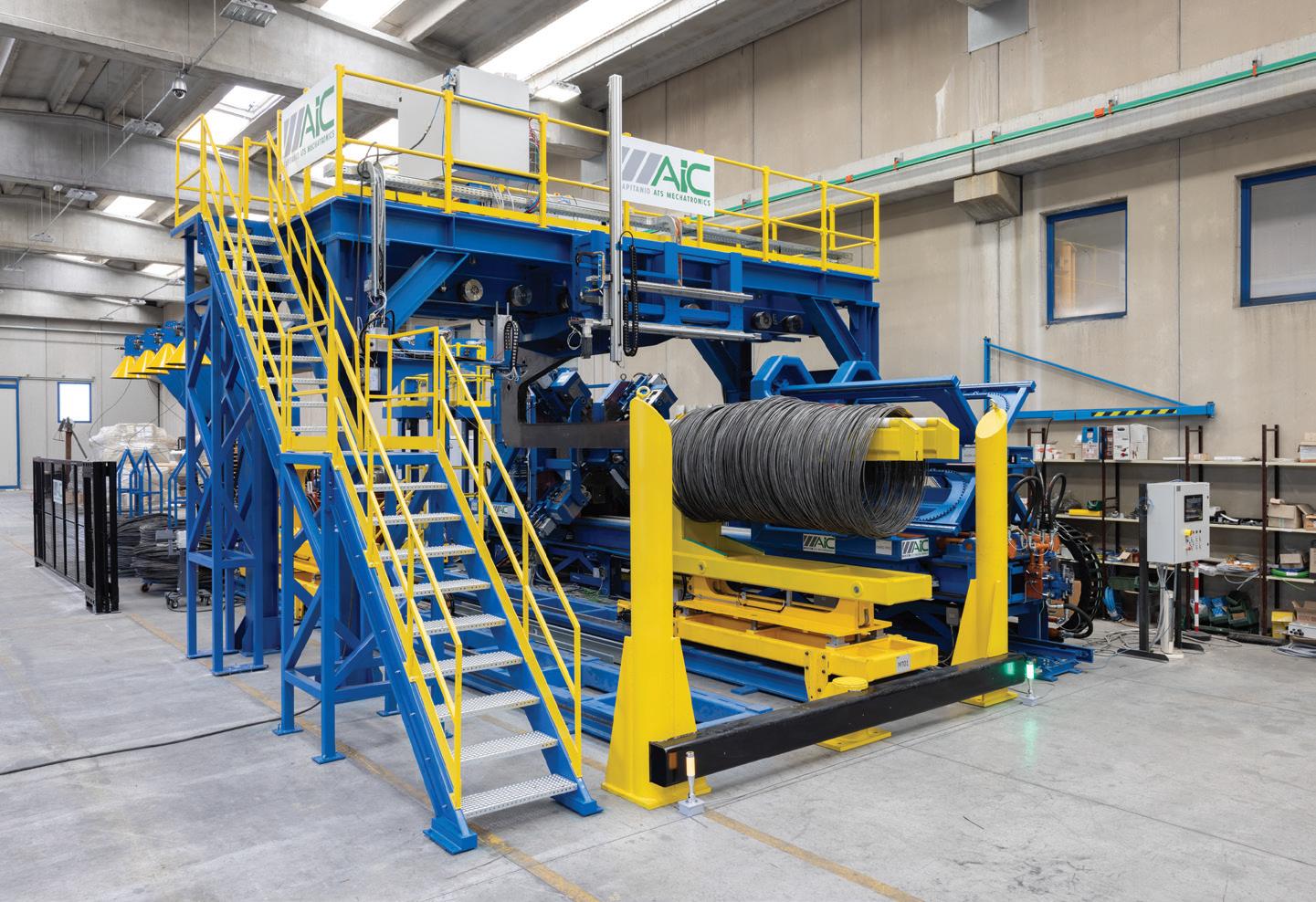
This Coefficient of Determination varied for the five tramp elements and is shown in Table 1
These were considered reasonably good results and were used in two ways.
The first was to evaluate the quality of the suppliers, by providing Ori Martin with a statistical value indicating the percentage of content of each tramp element for each material delivered by each supplier.
The second was to develop an application that tracks the loading operations of the crane for each heat and indicates the predicted level of tramp elements in the liquid steel that would result from the load while it is accumulated for the heat. This allows operators to see if the level of any tramp element risks exceeding a threshold and take corrective actions by choosing an appropriate material to load.
Every week, the model is retrained automatically in the cloud on the data containing all heats in the previous six months, excluding the last 150 heats, which are used to verify if the new model is more accurate than the previous model. If the accuracy of the new model has
improved with respect to the previous one, it is deployed automatically on the Tenova EDGE device in the plant, where it is invoked by the automation software.
We have learned a lot while designing, training, and evaluating these machine learning models, and were often surprised by how quickly these models learned, especially the ones involving image classification.
In general, we have dedicated more time to cleaning up the dataset of images and selecting good ones rather than trying different models and hyperparameters, in part because looking at thousands of images takes time, but also because we found that the quality of the images mattered more than their quantity. As we observe the models in production, we evaluate their classifications, and as we find more good images representing the various categories, especially if they were misclassified by the models, we add them to the datasets for future retraining.
We used image classification techniques
and not object detection, where the goal is to identify the location of each object together with its type, because our goal was never to locate material, only to give an indication of its type, or find out if any was present on the Consteel®
We have used object detection successfully in other projects, where it was important to locate the object, and the object had reasonably clear boundaries, which is not the case for metal scrap. For the model using process and sensor data, we have implemented automatic retraining, validating of the model, and automatic deployment.
This was possible because we could implement automatic preprocessing on the new data, and we could evaluate the performance of the model automatically. Machine learning projects do not end once the models are deployed. We are still evaluating their performance, gathering more images and data, regularly retraining them, and updating them in order to adjust them to the ever-changing world outside. �
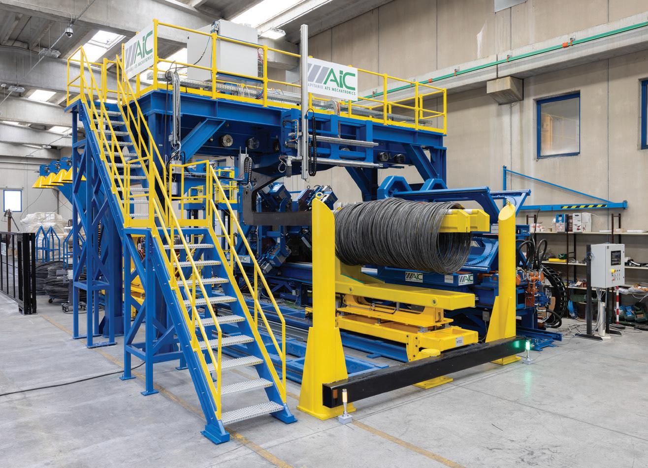
• Coil dimensional control system
• Weighing system
• Spray-paint marking system for visual product identification
• Automatic traceability system for the welded joint
• Laser marking for the
• Exhausted coil recognition system
Watch how it works: Key features include:


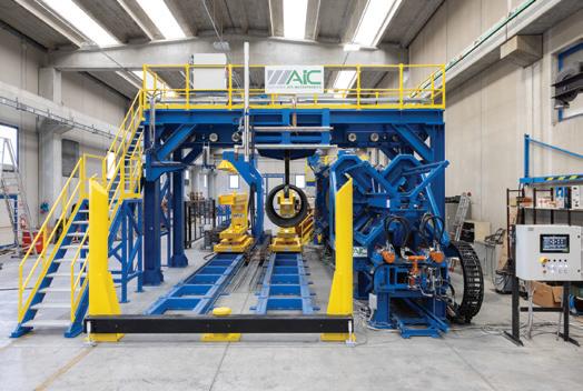
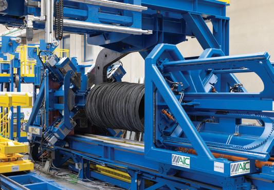
The New ATS Master Coil Binding Station compacts and bind multicoils that are between 1200 and 1600 mm in diameter and between 1 and 5 tons.
The system achieves a complete loading and unloading cycle in just 2.5 minutes. The compactor can also be installed in wire rod mills ensuring a compacting cycle time of 33 seconds.
Fully automated, the system ensures smooth operation, easy maintenance, and a scratch-free process.


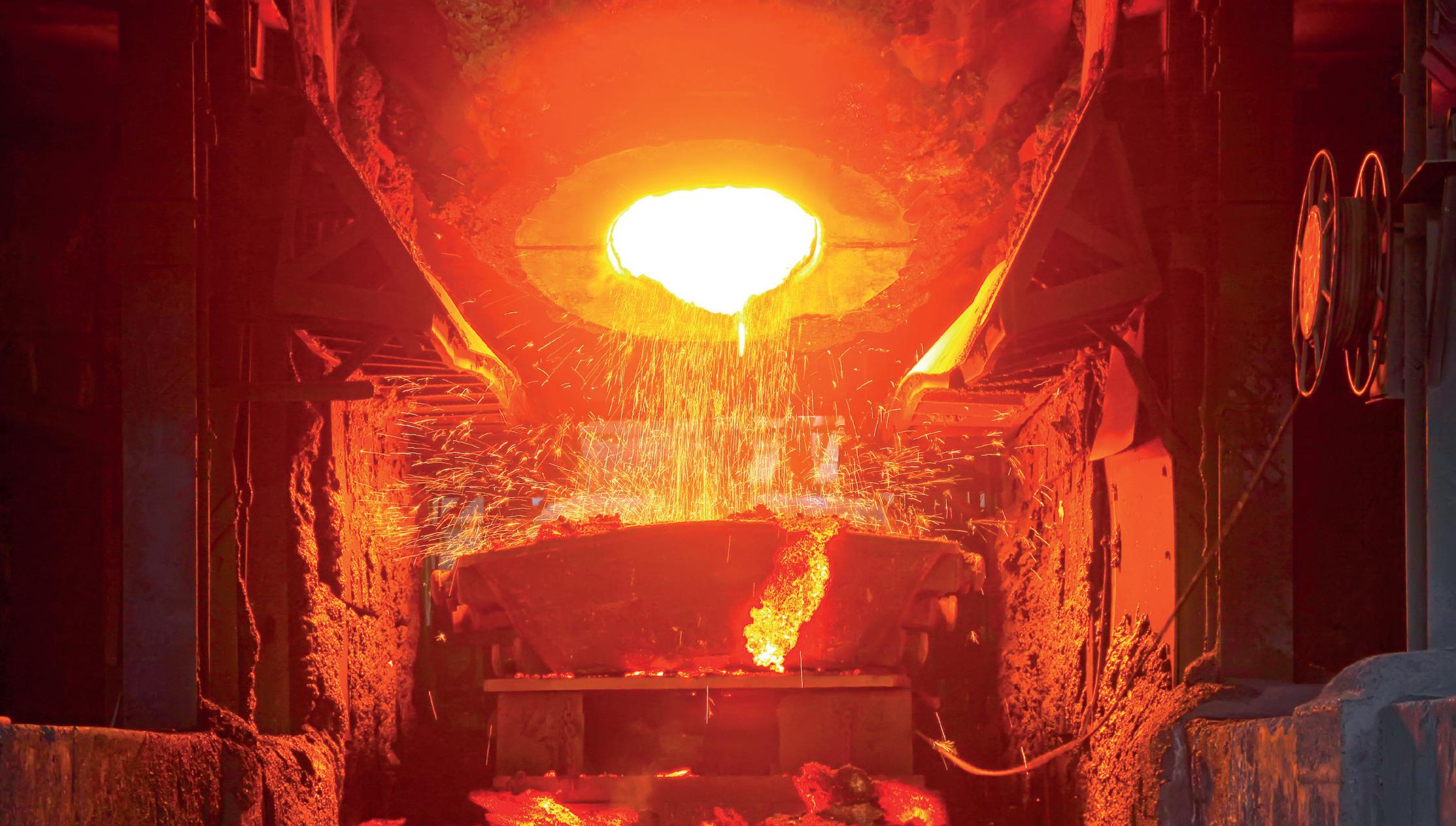
Bearing failures in the motor driving the impeller in the base of batch annealing coil furnaces experienced excessive vibrations as a result of rotor misalignment, debris accumulation causing imbalances and high temperature coming from the annealing furnace. The vibrations caused bearing oil seals to leak, resulting in poor lubrication leading to bearing failures. This was remedied by restricting motor speed to below 1600rpm to minimise vibrations which increased the availability of furnace bases enabling annealed coil output to increase 3.4% from 45,157t/month to 46,700t/m. By Suman Kant Thakur1, S Rath1, P Pathak1 & Madhu B N2
MODERN Cold Rolling Mills (CRM) at SAIL’s Bokaro steelworks are equipped with the latest technologies of coupled Pickling Line to the Tandem Cold Rolling Mill (PLTCM) and then to Hydrogen Batch Annealing Furnaces, followed by Wet Temper Rolling.
The Bell Annealing Furnace (BAF) for one of the cold mill lines, has a design capacity of 860kt/year and a present production rate of 540kt/year.
Annealing releases internal stresses in the coiled strip produced during cold rolling by controlled heating, soaking and cooling in a controlled atmosphere. The grain structure of the coil is also refined by this process, improving its mechanical properties. The batch annealing furnaces of this line consists of 47 annealing bases, on which coils are stacked three-high on edge and sealed within an inner cover. A bell type furnace (or hood) heated by gas burners is then lowered over the assembly (Fig 1). During the heating and soaking period, a protective gas of hydrogen is circulated inside the inner cover to ensure uniform heating of the coils and prevent
oxidation of the strip. The hydrogen gas is re-circulated by an impeller coupled to a motor mounted vertically below each base. Heat is transferred to the coil stack by the hot protective hydrogen gas by convection. The gas flows up the inner sides of the inner cover and returns down to the impeller through the centre of the coils. Due to the very nature of its design, the impeller is subject to a high temperature up to 1000oC, and a significant amount of vibration. The impeller is rotated by a motor installed vertically below the centre of the base. The high temperature of the motor and recirculation fan transmitted by the annealing furnace make them susceptible to structural degradation; resulting in a fall in overall performance of the annealing process and an increase in the risk of mechanical failures. Vibration in the base fan as well as its exposure to high temperature leads to frequent failure of its components such as oil seals, motor bearings and cooling fan bearings which are attached to the motor. Any breakdown of the motor in the furnace base or of its
components, leads to production loss from the furnace. Hence, a detailed study of the problem to identify solutions in terms of a mechanism to dampen these vibrations was undertaken by SAIL’s R&D Centre. Photographs of a failed impeller and base motor shafts are shown in Figs 2 & 3, respectively.
Out of many Non-Destructive Techniques (NDT) to monitor the condition of rotating machinery components, vibration-based techniques are found to be the most effective. Monitoring the vibration levels of a motor and its associated components can diagnose the reasons for frequent failure. In view of this a study was carried out to find the genesis of the vibrations leading to motor failure. The objective of the study included detailed vibration analysis and recommendations to mitigate failures.
Literature review
Failures in the gas circulation system of batch annealing furnaces can be mechanical or electrical. A mechanical issue may come from the fan, motor or
1R&D Centre for Iron & Steel, Steel Authority of India Ltd., Ranchi-834002, India 2Bokaro Steel Plant, Steel Authority of India Ltd., Bokaro- 827001, India email: skthakur@sail.in
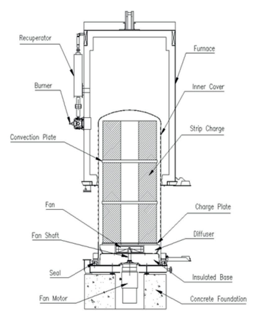
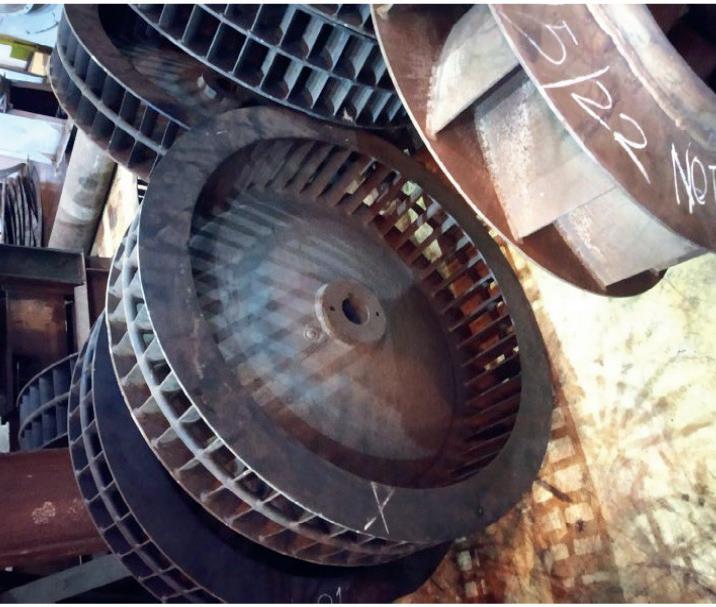
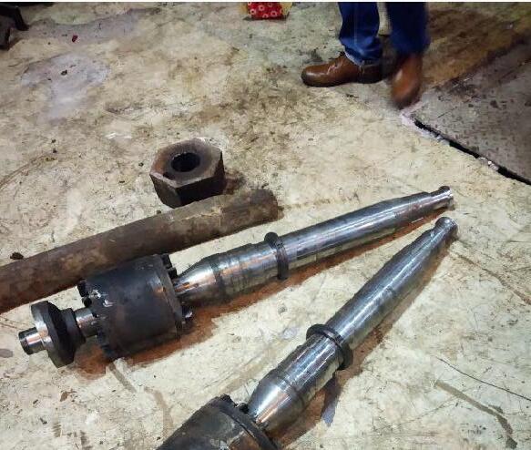
both. As with all rotating machinery, the most common vibratory force for vertically positioned motors is mass unbalance due to its ‘lollypop’ configuration. Critical machine components such as bearings, seals, gears, and couplings may be destroyed by the vibration caused by mass imbalance[1] In reality, manufacturing flaws such as casting porosity, uneven material density, manufacturing tolerances, and material gain or loss during use prevent rotating machinery from ever being perfectly balanced. These mass imbalances create a centrifugal force that bearings and support structures must counter. Apart from mass imbalance, internal misalignment, a bent shaft, looseness, resonance and oil seal leakage[2] are other reasons for high vibration. The fan and the end of the shaft
within the furnace are exposed to very high temperatures. Therefore a large amount of heat is conducted along the shaft to the motor drive end (MDE) bearing and to the motor bearing and housing. The drive end bearing is directly exposed to heat which may cause a reduced life and ultimately failure of the drive. Overheating may be controlled either by designing a suitable lubrication system or by air cooling. Effective cooling of the motor is, therefore, required, and it is especially necessary to effectively cool the bearing since the temperature of this must be prevented from exceeding its operating temperature limit. The shaft must be sealed off to stop gas leaks from the furnace and air leaks into the furnace. Due to the potential high levels of carbon monoxide or other hazardous unwanted gases, the annealed coil can be ruined by even a small air leak into the furnace.
In an electrical motor, a rotor revolves inside the bore of a stationary stator rotating coaxially within the stator. In
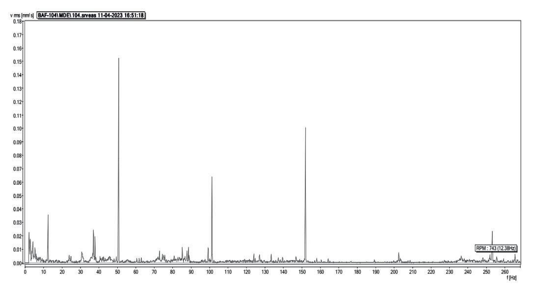
a healthy motor, the rotor is centrally aligned with the stator and the axis of rotation of the rotor is the same as the geometrical axis of the stator. This results in an identical air gap between the outer surface of the rotor and the inner surface of the stator. However, if the rotor is not centrally aligned, or its axis of rotation is not the same as the geometrical axis of the stator, then the air gap will not be uniform and the situation is referred to as air-gap eccentricity. In practice, air-gap eccentricity is a common fault in an induction motor. Air-gap eccentricity may occur due to any of the rotor faults such as rotor mass imbalance, bowed rotor, etc. Due to this air-gap eccentricity, in an induction motor, the electromagnetic pull will be unbalanced which causes high vibration. Apart from this, the motor may have other electrical faults such as broken rotor bars, stator faults, rotor faults, or winding faults[3] which can be detected by detailed analysis of the Motor Current Signature Analysis (which is not in the scope of this study).
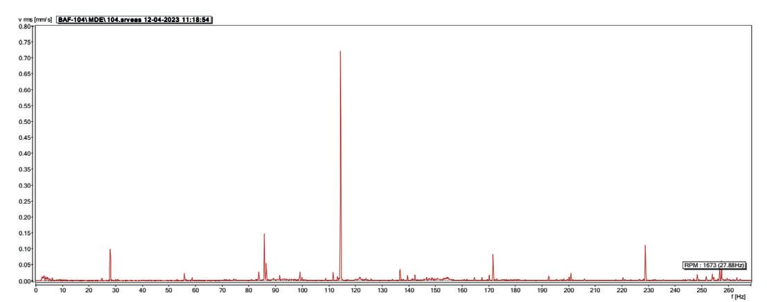
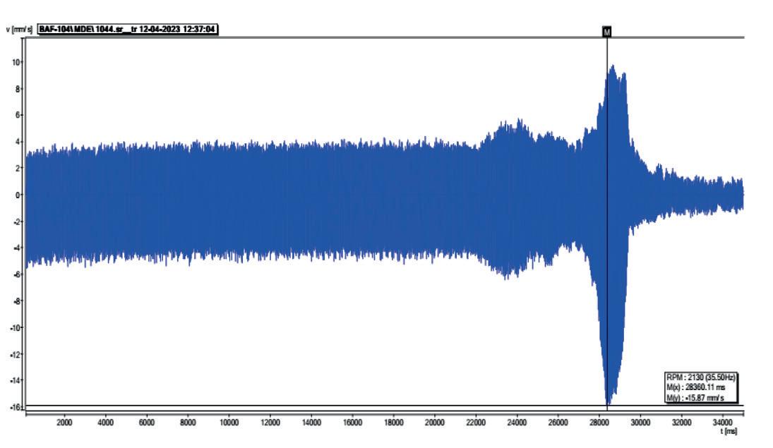
6. MDE bearing overall time waveform during coasting down from 2130rpm (35.5Hz) to zero.
Table 1. (below) Root Mean Square of vibration velocity at various motor speeds measured at the drive end bearing of the motor.
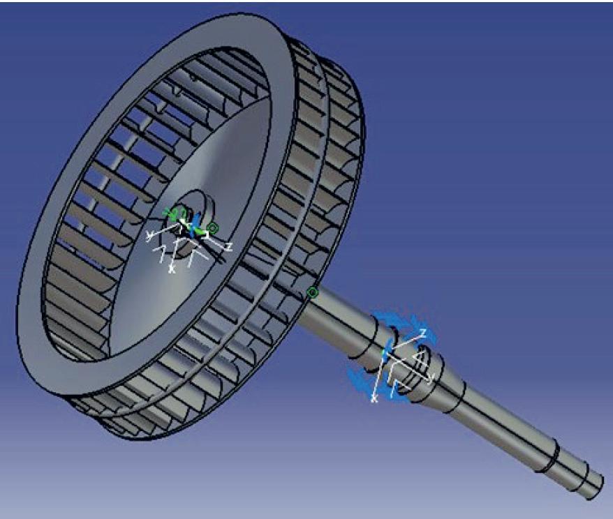
Vibration signature analysis is widely used as a useful tool for studying progressive machine mechanical malfunctions, and also forms the baseline signature for further comparative monitoring to detect mechanical faults[4].Vibration monitoring is based on the principle that the whole system produces vibrations. When a machine is operating properly, the vibration is small and constant; however, when faults develop and some of the dynamic processes in the machine change, there will be changes in the vibration spectrum. Effective vibration analysis starts with obtaining an accurate signal from a measuring point with the help of an accelerometer. The analogue signal is then converted into a digital signal using an analogue to digital converter. The digital signals can be processed directly or can be processed using some formula depending upon the need of the user[5]. Based on vibration readings, spectrum analysis and phase analysis are carried out to determine the cause of high vibrations. Spectrum analysis enables this complex waveform to be untangled and make a representation of its original components on a diagram showing frequency on the X-axis and amplitude vertically. This is known as a vibration spectrum and is extremely valuable for fault diagnosis. The conversion from time to frequency is achieved using Fast Fourier Transform (FFT). Phase analysis is a collection of phase measurements made on a machine or structure and evaluated to reveal information about relative motion between components. In vibration analysis, phase is measured using absolute or relative
techniques. The mass unbalance can be identified by observing the spectrum at running frequency with steady phase conditions. An experimental study of the effect of flexible supports on the stability and imbalance response of a flexible rotor supported by fluid film bearings[6] has been studied. The mass imbalance can be corrected by ex-situ or in-situ balancing. In ex-situ balancing the unbalanced rotor is dismantled from the motor and taken to a balancing rig for mass balancing. With in-situ balancing the actual assembled condition of the motor is balanced at rated rpm, reducing the chances of assembly error and ensuring the accuracy of balancing is high.
A team of specialists trained in vibration analysis and balancing of motors measured vibrations at seven drive end bearing housings of the annealing base motors under various operating conditions. The motors chosen were identified as suffering a high vibration history. One of the base (No 1) was selected for detailed analysis as that base showed a higher amplitude of vibration compared to the others. For analysis, the motor was run at 743rpm (12.38Hz) initially without load and with the annealing cover removed. The annealing base was then loaded with coils, the inner sealing cover put over, the Bell furnace lifted on to this assembly and the heating and cooling cycle started. The motor was rotated at 1673rpm (27.88Hz) to drive the impeller.
The vibration amplitude of motor No
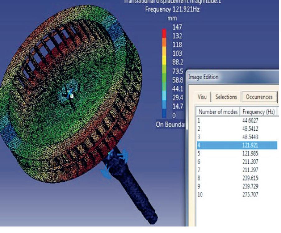
frequency.
1 in the unloaded condition is shown in Table 1 row A and a sampled spectrum collected at 743rpm (Fig 4). The base was then loaded with coils, covered with the inner sealing cover and furnace and heated to annealing temperature, followed by cooling. The amplitude and spectrum of the base motor were again measured, now at the normal operating speed of 1673rpm (27.88Hz) during the cooling phase of annealing. The amplitude and spectrum obtained are shown in Table 1 Row B and Fig 5 respectively. An over speed test was then carried out increasing the speed to 2130rpm (35.5Hz) and the vibration amplitude measured (Table 1 Row C). Thereafter the power to the motor was turned off allowing it to coast down from 2130rpm to 0rpm to determine the overall vibration response. A time wave form was recorded as shown in Fig 6
In a detailed vibration analysis of Base No1, several observations were made regarding vibration amplitude and frequency behaviour under these different conditions. When the impeller and motor were running unloaded at 743rpm
2 1658 0.17
• Low vibration.
• Motor can run up to 1650rpm 1658 0.36
3 1658 0.8-0.9
• Vibration peaks at running frequency of 27.63Hz (1X) is dominating
• Motor bearing fault frequency at 113Hz for bearing 6220 may be present
• Motor may check for misalignment, clearance/ looseness and rotor bar health condition 1658 1.5
4 1658 0.16
5 1658 0.8-0.9
• Low vibration.
• Motor can run up to 1650rpm
• Vibration peaks at running frequency of 27.63Hz (3X) is dominating
• Misalignment and excessive axial clearance may be reason for the (3X) vibration peaks 1658 1.7
6 1665 0.16-0.2
1680 0.55
7 1500 0.6
• Low vibration.
• Motor can run up to 1650rpm
• Low vibration.
•Motor can run up to 1650rpm
(12.38Hz), the overall vibration levels were observed to be very low. Specifically, the amplitude at the running frequency of 12.38Hz first harmonic peak (1X) was notably lower compared to running at 50.63Hz or its higher harmonics (101.25Hz, 151.88Hz, etc.). In Fig 4, a frequency of 37.9Hz and its harmonics were also detected, suggesting additional vibrational influences at these frequencies. Table 1B provides data showing that overall vibration remained low when the system is operated at 1673rpm under loaded cooling conditions. In Fig 5, the amplitude at the running frequency of 27.88Hz (1X) was minimal compared to 114.38Hz. Additionally, harmonics, showing as peaks in the trace, at 114.38Hz and 228.75Hz, were also observed, indicating a pattern of harmonic vibrations at this operational speed. However, the vibration analysis revealed different behaviour at 2130rpm (equivalent to 35.5Hz) under loaded cooling conditions. The overall vibration amplitude increased at this speed. In Fig 6, it was observed that during coasting down, the amplitude of the drive end bearing remained steady at around 4.0mm/sec while running at 35.5Hz. Upon switching off the motor, the vibration amplitude initially decreased to 3.0mm/sec but then spiked abruptly to 15.87mm/sec thereafter gradually reducing again. This spike may suggest a transient resonance effect or a structural response triggered by the deceleration process. These findings indicate complex vibration dynamics that
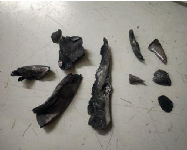
vary with the operational speed and load conditions, emphasizing the importance of monitoring specific frequencies and harmonics in maintaining optimal vibration levels.
A CAD model of the motor shaft and impeller assembly was prepared from drawings supplied using CATIA software. The assembly model is shown in Fig 7 Finite Element (FE) modal analysis of the impeller with motor shaft was performed by using CATIA to determine the natural frequencies and mode shapes of vibration. The first 10 modes’ corresponding frequencies of the present configuration are listed in the Finite Element analysis of the impeller in Fig 8
Phase measurement was not possible when in the loaded condition due to the unavailability of an exposed rotating part for phase measurement at a specified rpm. Phase measurement was possible up to 740rpm without the inner cover in place
as the motor or impeller could be viewed rotating. The overall vibration was very low when the unloaded impeller and motor were rotated at 743rpm (12.38Hz). The amplitude of the running frequency at 12.38Hz (1X) was low compared to the harmonic peaks at this speed shown in Fig 4 which occur at 50.63Hz and 101.25Hz, 151.88Hz etc. A frequency of 37.9Hz and its harmonics was also observed in this vibration spectrum, Fig 4
From Table 1B it is evident that the overall vibration at 0.81mm/sec is low at 1673rpm determined during cooling with coils loaded. Fig 5 shows that the amplitude at a running speed of 1673rpm – 27.88Hz (1X) frequency – was very low compared to the observed 114.38Hz harmonic peak in the spectrum. In turn, a harmonic of this 114.38Hz peak was also observed at 228.75Hz. Table 1C shows that the overall vibration increased at 2130rpm (35.5Hz) in the loaded condition, during cooling. Fig 6 shows that the overall amplitude of the MDE bearing vibration during coasting down from 35.5Hz was almost constant (4.0 mm/sec) after switching off the power to the motor. The amplitude initially reduced to 3.0 mm/sec but increased abruptly up to 15.87mm/sec. Thereafter, vibration amplitude reduced gradually. From Fig 8, it was found that the fourth mode’s natural frequency of the impeller with motor shaft was 121.921Hz.
Vibration analysis of other bases
Bases 2 to 7 were also selected for examination during three production campaigns. Motors ran under full load and temperature conditions at speeds of 1500 to 1680rpm with 1658rpm (27.63Hz) being the norm. The vibration amplitude for each is shown in Table 2
The vibration analysis of these six remaining bases revealed the following:
• Given that the overall vibration values are low, periodic monitoring of the vibration spectra over time will allow for more meaningful analysis. If vibration levels increase, the dominant peaks and their potential causes can be assessed accordingly.
• The current low vibration levels suggest that the motor can operate safely within the acceptable limits specified by the manufacturer. Routine checks are recommended to ensure these levels remain within the acceptable range.
• A recurring pattern observed in the
spectra, with dominant peaks appearing at 3-times (3X) the running frequency, may indicate possible misalignment or excessive axial clearance.
• It is recommended to inspect the motor for potential issues such as bearing faults, misalignment, or clearance/ looseness at the next available maintenance opportunity, or sooner if overall vibration levels rise above the manufacturer’s warning threshold.
• These findings provide guidance for ongoing monitoring and proactive maintenance to ensure the motor remains within safe operational parameters.
Broken part of the coil/binding wire/ balancing masses etc, have been found in some of the motor bases during inspection between the loading and unloading cycle of the furnaces. Illustrations of some of these incidents are shown in Figs 9 to 12
It is recommended that screens be incorporated in the bases such as that illustrated in Fig. 13, to serve as a barrier against the ingress of particles into the impeller. This precautionary measure not only prevents the entry of contaminants but aids in mitigating abnormal vibrations and reducing the load on the motor base.
The results of a detailed study of failed bearing components is illustrated in Fig 14, a, b & c. The following observations are:
• The races had rubbing marks on the internal and external surfaces.
• The outer surface of the inner race (fixed on the shaft) had black marks representing oxidation and rusting of the surface.
• The inner surface of the inner race (surface holding the ball-bearings) had sliding marks representing sliding wear of the surface due to insufficient lubrication.
• The bearing balls have sliding marks along with small wear scars.
• The sliding marks on the balls represent insufficient lubrication and the inability of the lubricant film to sustain the applied load.
• Small wear scars were observed on two of the bearing balls representing wear due to inadequate lubrication.
• The inner surface of the outer race (surface holding the balls) has sliding marks representing sliding wear of the surface due to insufficient lubrication.
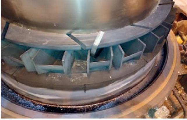
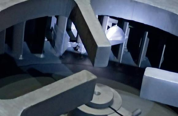
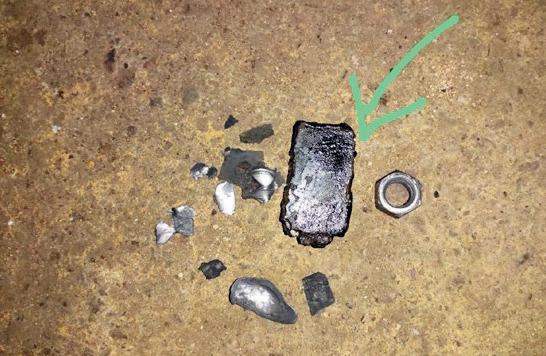
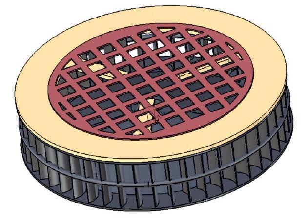
on the bearings, it is inferred that bearings were experiencing lubricant starvation which would result in increased bearing temperatures and wear. Where there was insufficient grease between the sliding surfaces, sliding wear of the contacting surfaces occurred. The fit between the inner race and the shaft may have become loose as a result of which lubricant/fluid became trapped between these resulting in oxidation of the surfaces.
Insufficient lubrication can result in the breakdown of the protective film between the bearing rolling elements leading to the observed sliding wear in areas subjected to high loads. Inadequate lubrication increases the risk of metal-to-metal contact, but excessive lubrication induces heat build-up and friction as rolling elements attempt to displace surplus grease. To avert bearing failure, it is crucial to adhere to the manufacturer’s guidelines for proper lubrication, ensuring the recommended lubricant viscosity at the operating temperature to enhance bearing lifespan. Additionally, frequent bearing replacements can introduce slack in the bearing housing, contributing to recurrent bearing failures. Therefore, minimising the frequency of bearing replacements is advisable to prevent such issues.
Optimising motor performance is essential during the annealing cycle, and running the motors at a controlled speed of up to 1600rpm has proven crucial in minimising vibration. Elevated motor speeds beyond this threshold generate high vibration levels, posing a significant risk and consequently serving as a root cause for bearing failures. By imposing a speed limit of 1600rpm, a notable reduction in vibration levels has been achieved across all the annealing bases. This strategic adjustment has not only safeguarded the health of the bearings, but has also yielded positive outcomes in terms of overall base availability.
• The outer surface of the outer race (surface fixed in the housing) had light-to-heavy scratch marks along the circumference, representing play (movement) of the outer race in the bearing housing.
On the basis of the observations made
The enhancement in base availability has increased from 32 bases to 44 increasing monthly throughput from 45,157 to 46,700t/m, an increase of 3.4%, reflecting the success of this approach. Improved base availability has translated into a commendable increase in production rates at the annealing furnace. Thus, restricting motor speed is crucial in minimising vibration of the base motors, reducing the failure rate and so leading to improved base availability.
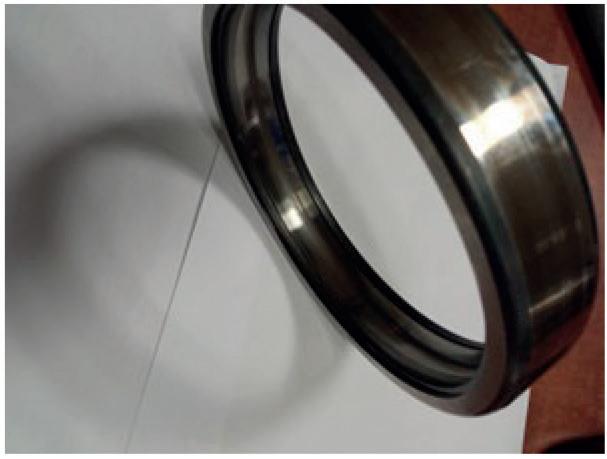
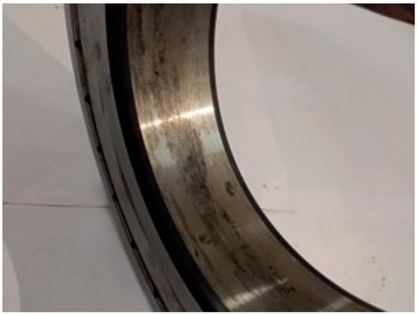
Acknowledgement
The authors thank the management of R&D Centre for Iron & Steel, Steel Authority of India Ltd., Ranchi for their support.
References
1. Aleksandar Brkovic, Dragoljub Gajic, Jovan Gligorijevic, Ivana Savic-Gajic, Olga Georgieva, Stefano Di Gennaro. Early fault detection and diagnosis in bearings for more efficient operation of rotating machinery. Energy, Volume 136, 2017, Pages 63-71,
ISSN 0360-5442, https://doi.org/10.1016/j. energy.2016.08.039.
2. Živković, Vladimir & Grkovic, Vojin & Kljajic, Miroslav. (2024). The instigating factors behind the occurrence of vibration in steam turbines: A review analysis. Thermal Science. 98-98. 10.2298/TSCI240105098Z.
3. Didier, G., Ternisien, E., Caspary, O., & Razik, H. (2007). A new approach to detect broken rotor bars in induction machines by current spectrum analysis. Mechanical Systems and Signal Processing, 21(2), 1127-1142.
4. Ramachandran, K.P.: Vibration signature analysis for machine health monitoring and fault diagnosis. Caledonian Journal of Engineering. (2004) 26–39
5. Mills, S. R. W.: Vibration Monitoring and Analysis Handbook (INST397). The British Institute of Non-Destructive Testing. ISBN9780903132397 (2010)
6. Vázquez, J.A., Barrett, L.E., Flack, R.D.: A flexible rotor on flexible bearing supports: stability and unbalance response. ASME J. Vibr. Acoust. 123 (2001) 137-144
In the eyes of coating technology supplier Emisshield, innovation drives the industry forward – and companies that are willing to embrace change, are the ones that remain on top. We speak to Alexander Alto*
1. How are things going at Emisshield? Is the steel industry keeping you busy?
Emisshield continues to experience growth in the industry, but only when companies accept modernization. Our high-emissivity coatings are increasingly being adopted in various steel manufacturing processes, enhancing productivity, energy savings, and the protection of vital manufacturing equipment.
2. What is your view on the current state of the global steel industry?
The global steel industry is currently navigating challenges such as overcapacity and environmental concerns. However, there is a notable shift from key players toward adopting advanced technologies to improve efficiency and reduce carbon emissions. This shift is exactly what we hoped for, and we are a huge proponent of it.
3. In which sector of the steel industry does Emisshield mostly conduct its business?
Emisshield is heavily involved in the manufacturing process, specifically in equipment such as reheating furnaces, electric arc furnaces, and annealing furnaces. Coating the substrate in these furnaces significantly increases productivity and energy savings based on furnace PLC adjustments.
4. Where in the world are you busiest at present?
North America and the Middle East are key areas for us. We work closely with Chase Nedrow and Gulf Consulting Group/Desert World, respectively, as our biggest players right now, and we are extremely happy with the results.
5. Can you discuss any contracts you are currently working on?

Emisshield has collaborated with leading steel manufacturers like Outokumpu and BAOSTEEL to apply our high-emissivity coatings, which have proven to achieve energy savings of 4-5%, reduce CO2 emissions by 5%, and lower NOx emissions by 3%.
6. How do you get people to see the real value of Emisshield and the impact it has on their manufacturing process?
We constantly face this issue, but to put it into perspective: If I spend $500K USD annually on fuelling an annealing furnace, applying Emisshield to the substrate could yield a 5% energy savings – that’s $25K USD back in your pocket. Not to mention the CO2 and NOx reductions, along with other production efficiency and protective benefits. These benefits result in a return on investment of less than one year.
7. What are your views on Industry 4.0 and steelmaking?
The Fourth Industrial Revolution has significantly improved the manufacturing process. We believe it presents new solutions for innovating these processes,
*Marketing project manager, Emisshield.
which is exactly what we aim to do.
8. In your dealings with steel producers, are you finding that they are looking to companies like Emisshield to offer them solutions in terms of energy efficiency and sustainability? If so, what can you offer them?
We get these questions all the time, and they are always major topics: How can I save energy? How can I improve product quality? How can I improve production efficiency? We provide solutions for all these concerns across various applications – and we have already done so, giving our customers a competitive advantage in their respective industries.
9. How quickly has the steel industry responded to ‘green politics’ in terms of making the production process more environmentally friendly? Are they succeeding or fighting a losing battle?
The steel industry has been progressively responding to environmental concerns –some companies more than others –by adopting technologies that reduce emissions and improve energy efficiency. We can apply our coatings to different substrates, heating elements, and even combustion engines, resulting in lower emissions and better energy savings.
10. Where does Emisshield lead the field in terms of new technology?
For over 10 years, $30 million has been spent on research and development for Emisshield. We lead the market with coatings that offer the best properties, extreme bonding strength, hardness, and dedicated support teams.
11. How do you view Emisshield’s development over the short-tomedium term?
In the short-to-medium term, Emisshield promises significant improvements to the production process. In the long term, we ensure incredible protection and longevity for manufacturing equipment.
12. China dominates global crude steel production. How should the industry react to this situation?
Emisshield has driven major process improvements in China’s steel industry, which helps them maintain their position at the top. Industry reluctance to adopt new processes gives China a growing edge. If US companies lead the way in innovation, we may see a power shift in the industry.
13. Where do you see the most innovation in terms of production technologies – primary, secondary, or more downstream?
Downstream, particularly in reheating and annealing furnaces, sees the biggest improvements. For example, our ability to take technology that’s 40 years old and make it operate like new is just incredible –I’ve seen this firsthand. It’s amazing.
14 How optimistic are you about the global steel industry going forward, and what challenges do global producers face in the short-to-medium term?
We are very optimistic about the global steel industry’s future, given its efforts to adopt innovative technologies and sustainable practices. However, challenges such as reducing carbon emissions and managing overcapacity persist.
15. What similarities can be found between the space sector and the steel industry?
Both sectors operate under extreme conditions, requiring advanced materials and thermal management solutions. Emisshield coatings, originally developed for space shuttles’ re-entry into Earth’s atmosphere, are now utilized in the steel industry to enhance thermal efficiency.
16. What exhibitions and conferences will Emisshield be attending over the next six months?
We are currently exploring AISTech 2025 from 5-8 May in Nashville, TN, and later in the year, METALCON 2025 from 2123 October at the Las Vegas Convention Centre.
17. Emisshield is headquartered in Blacksburg, Virginia. What’s happening steel-wise in the area?
We are located within a collegiate-level R&D centre. Because our location has historically been a hub for innovation and technology,
we actively collaborate with local industries to promote advanced thermal management solutions.
18. Apart from strong coffee, what keeps you awake at night?
Strong coffee fuels our coatings, our global communication, and our commitment to customers. But another thing that keeps us up? Companies constantly trying to reverse-engineer our products. Fortunately, innovation isn’t so easily copied – especially when it’s backed by expertise and NASA certification.
19. If you possessed a superpower, how would you use it to improve the global steel industry?
If Dr. John Olver, CEO and president of Emisshield, Inc., had a superpower, he would create a coating with a perfect emissivity of 1.0 – a perfect blackbody. This would grant us the ability to control 100% of the heat in any application, instrumentally increasing steel quality and productivity. Unfortunately, due to elemental limitations, the materials we use can only achieve a 0.97 emissivity right now. Other companies producing these coatings typically reach an emissivity range of 0.7 to 0.8 and do not offer the same hardness and protective properties as ours.�
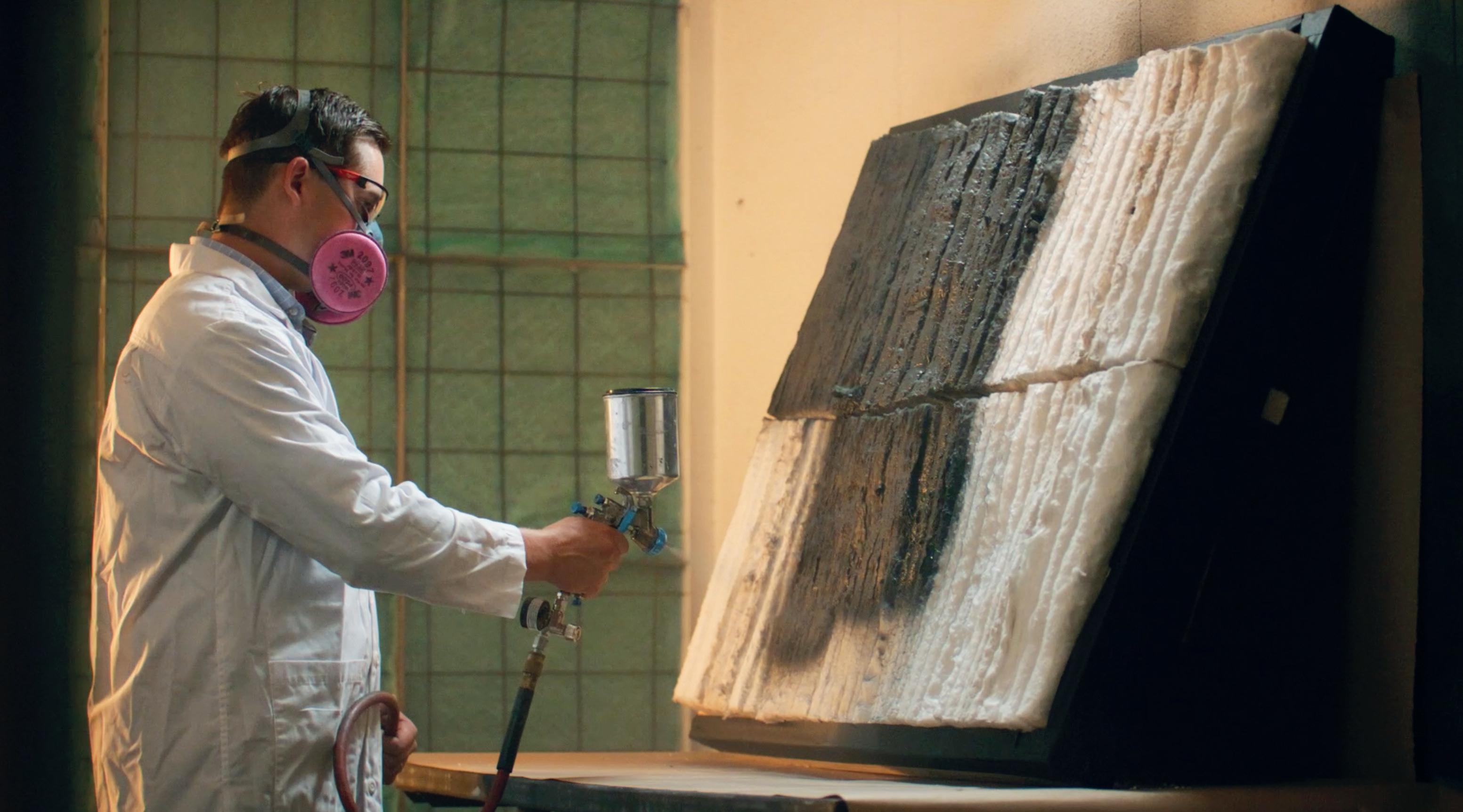
Much credited as the inventor of the coke blast furnace which enabled him to cast bellied pots in cheap iron, rather than traditional expensive brass, using green-sand moulds, this article shows that Darby was in fact ‘standing on the shoulders of giants’, both technologies having been previously pioneered.
By Peter King*
SINCE the mid-20th century (if not before), Abraham Darby has been regarded as the pioneer of smelting iron with coke at Coalbrookdale. This makes it surprising that his patent was for making cast iron bellied pots, not for coke smelting. Previous articles in this series have shown that neither in smelting iron with coke, nor in making pots, was his role as an innovator as clear as has been supposed.
Smelting with coal may start with Dud Dudley, the subject of the first article, published in Steel Times International’s November/December 2024 issue. Dudley’s sister, Jane, married Richard Pershouse. They had a son Edward and a daughter Margaret, who married John Darby (a locksmith) who, in 1649, took a 21-year lease of part of Dudley Old Park which included a lodge or cottage. The description in the lease would fit Old Park Farm, which was near Wrens Nest Hill. If so, John may have been farming about 75 acres. Here, his grandson Abraham Darby was born in 1678. The family were Quakers. Abraham was apprenticed, most likely at the age of 14, to Jonathan Freeth of Birmingham, a malt-mill maker, but later references describe Abraham as a blacksmith. He completed his apprenticeship in 1699 and moved to Bristol to set up in business there. He soon took a young Quaker called John Thomas as his apprentice in the malt-mill trade.
In Bristol he became involved in the brass industry with partners. Five Quakers had petitioned the Privy Council for incorporation in 1700, but nothing came of this. However, Darby joined a partnership in 1702, which was expanded in 1706 by the addition of four new partners (totalling
eight). They operated as an unincorporated joint stock company, called the ‘Bristol Brass Company’. Abraham Darby was apparently their ‘active man’. The company leased Baptist Mills in Bristol, and he recruited Dutch workmen to run it. They made brass by heating copper and calamine (ZnCO3) together in crucibles.
Abraham branched out further with a foundry at Cheese Lane, Bristol, where the employees included John and James Flowery, previously London brass-founders. There he managed to cast bellied iron pots in green sand. In this, damp sand was packed around iron (or brass) patterns placed in a two or four-part moulding box of wood or iron which could be dismantled to remove the pattern, leaving the sand with the impression of the pot. This was then reassembled and clamped for casting the pot. This was a cheaper alternative to the established method of casting in loam – a mixture of clay, sand, water and organic binder – which was plastered over a pattern made of friable material such as loam or clay or sections of wood. The assembly was baked hard and the pattern broken out, or wooden blocks removed, to reveal a cavity to pour the molten metal into while the mould was still hot, this reducing the likelihood of thin sections solidification to white iron. His apprentice, John Thomas, claimed to have perfected the process when ‘Dutchmen’ failed. These men may have been the former London founders John and James Flowery, possibly of Huguenot extraction. Certainly, Thomas entered into articles in 1707 to work for Darby and keep his secrets. To cast thin-walled iron pots in green sand moulds requires a fluid iron achieved by a high silicon and phosphorous content of the metal which also results in solidification to the less brittle form of grey cast iron. Such iron normally requires a furnace using coal or coke as fuel and reductant, rather than charcoal. Darby likely had a source of coke pig iron. He certainly obtained pig iron from some of the Foley Forest Partnership’s furnaces around the Forest of Dean, but these made charcoal pig iron. It is possible that coke pig iron was obtained from Peter Chettle’s Gwendraeth Furnace in South Wales (see the March 2025 issue of Steel Times International).
Table 1 gives the analysis of thin-walled pots cast at Coalbrookdale in the late 18th Century, compared with the iron beams of
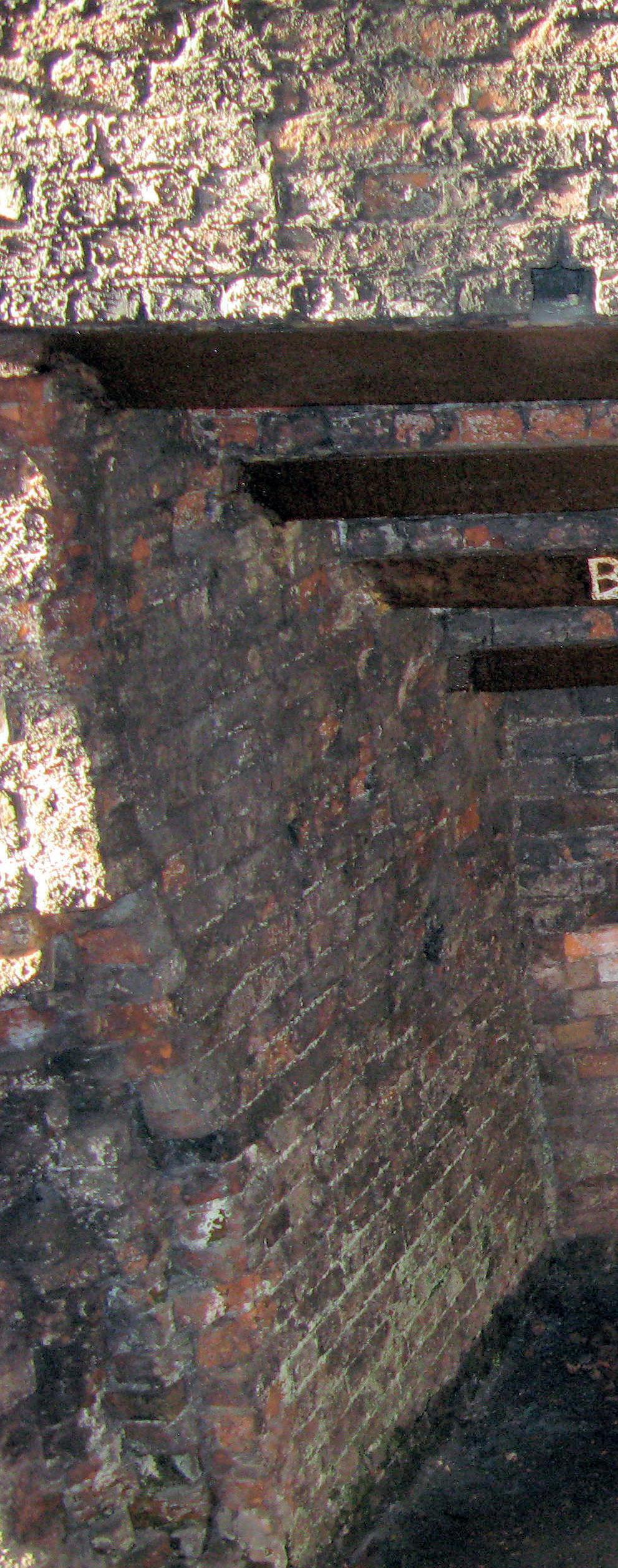
the ‘Iron Bridge’, built some 75 years later by Abraham Darby III in 1779, from metal cast at the same furnace Abraham Darby had first used, but heightened to increase capacity. Note the much higher silicon and phosphorous contents of the thin-walled pots, probably achieved by careful selection of the ore and coal source, compared with that of the much thicker sections of the iron bridge.
Needing his own source of coke pig iron, Darby chose Coalbrookdale, where Shadrach Fox, and his foundry-man Roger Downes, had been making coke iron, until the furnace was stopped by flooding around 1703 (see Steel Times International’s January/February 2025 issue). This was the context for Darby’s clandestine recruitment of Roger Downes (described in Steel Times International’s March 2025 issue), who
*Dr King serves on the Council of the Historical Metallurgy Society and is the author of a book and many articles on the history of the iron and steel industry
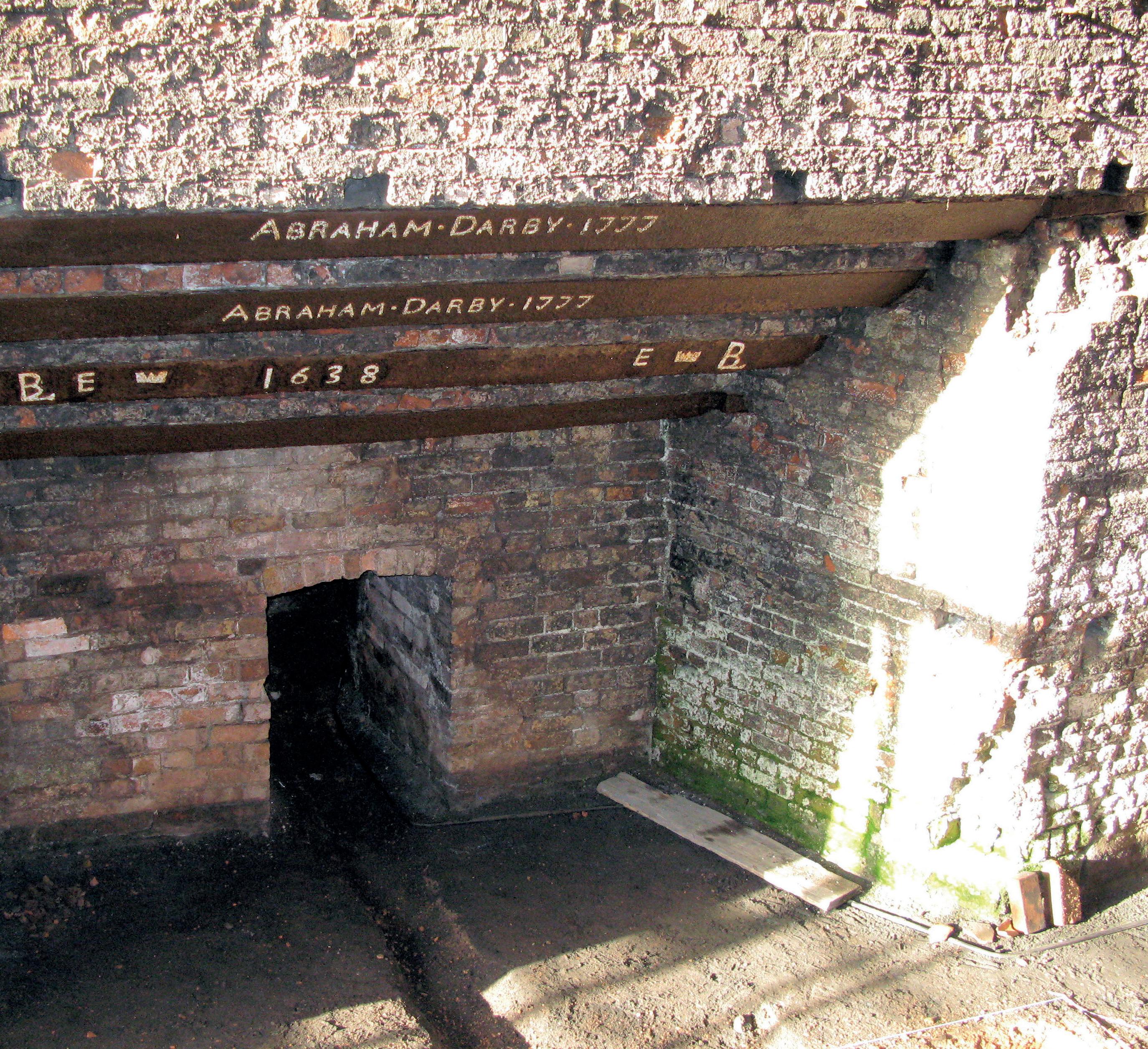
The casting arch of Darby’s Coalbrookdale furnace later enlarged by his grandson to make castings for the Iron Bridge in 1777 (See Steel Times International’s December 2024 digital issue for the disputed 1638 date on lower lintel recorded in early photographs as 1658).
Sources: R Williams & Forsyth.
was the one artisan that could testify that Darby’s patented process of casting bellied pots in green-sand, using coke iron, may not have been unique. It is likely that Downes travelled to London to see his family and then joined Darby in Bristol. He then went with Darby to Coalbrookdale. The furnace was repaired and blown-in in February 1709.
Darby was also involved in a copper and brass venture in Shropshire, though probably not as a partner. In 1710, he and Thomas Harvey negotiated the lease of Tern
Mills (close to Tern Hall, now Attingham Hall) on behalf of a Quaker company (with Thomas Harvey as an active partner). The mill was to roll brass plates and iron hoops and slit bar iron into rods. A copper mine at Myddle, Shropshire, was leased to Abraham Darby and Company of Bristol. Thomas Harvey later complained about Darby’s failure to renew the lease of a mill used by him for grinding the zinc ore and calamine, at Coalbrookdale, to which ‘callumy’ (calamine) was brought up the river Severn. As smelting was prohibited at Tern, copper
may have been smelted and combined with calamine to make brass at Coalbrookdale.
Many of the partners left Tern Mill in 1714 and their shares were taken over by investors from Wolverhampton, including ironmonger, William Wood. They added a forge at Tern mill, which proved to be a considerable annoyance to the owners of Tern Hall.
At Coalbrookdale, Darby established a viable business making iron pots and other holloware. He seems to have experimented with different kinds of coal, before settling on the local clod coal as the appropriate fuel and reductant. For a time, he had partners in his Coalbrookdale Works, but he bought most of them out, mortgaging his shares to Thomas Goldney, a Bristol Quaker merchant. His success encouraged him to lease Vale Royal Furnace in Cheshire and a potential furnace site at Dolgun near Dolgellau, North Wales but these were
never used during his lifetime.
Darby tried to enforce his patent monopoly in making iron bellied pots and brought proceedings in 1709 against William Rea of Monmouth, the manager of the Forest Works, and John Legas, Rea’s pot-founder at Blakeney Furnace, in the county of Gloucester. Legas denied infringing the patent, saying he used some clay or loam in his moulds, as he had been brought up to do. Rea said he knew nothing, except by information from Legas. Another defendant, Charles Axford (a Bristol founder) and one of his partners, said that Darby was a ‘[black]smith, not a founder’; Axford said he made his moulds as he had long done for brass; and that making bellied iron pots had already been practised by Roger Downes for Mr Chettle in Carmarthenshire, Wales. Darby made a further claim against Thomas Moore and Edward Raby of Stourbridge, Timothy Gough of Bridgnorth, and George Bartlett of Bristol, but they all denied infringing the patent.
Darby died intestate in 1717. His widow Mary sold off Dolgun furnace and agreed
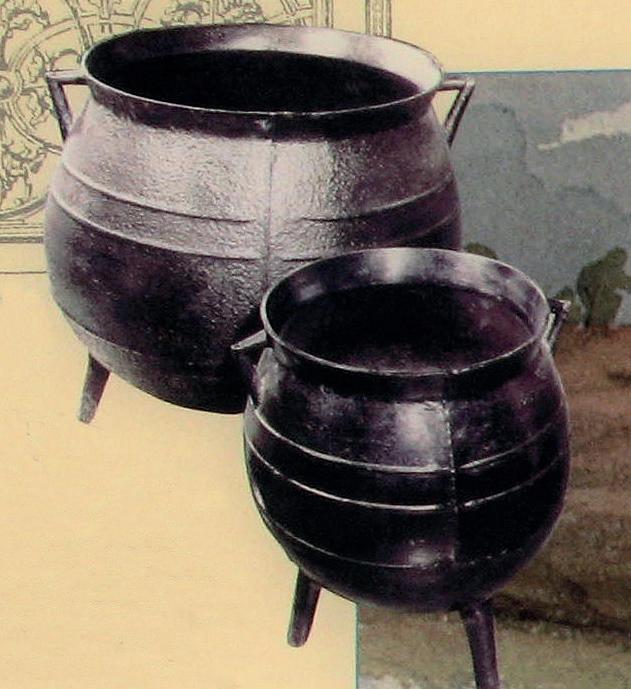
Thomas Baylies (who was managing Coalbrookdale) could take over Vale Royal, but Mary then died, and Baylies took out a creditor’s grant of administration. Thomas Goldney then converted his mortgage into shares in the company and brought in Richard Ford as a partner, to run it.

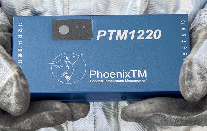


Ford later married the eldest daughter of Abraham and Mary Darby. When Abraham, Darby’s eldest son was old enough, he was trained by the company, a small share in it having been redeemed by an uncle for the benefit of the orphaned Darby children.
Abraham Darby’s achievement was in establishing an enduring business making cast iron pots and other goods. His successors had customers who acted as wholesalers in Gainsbrorough, Bristol, and London, as well as themselves supplying retailers in the Midlands and beyond. The Bristol Brass Company operated for many years, but without Darby. Who operated his Cheese Lane Foundry in this period is not clear, but later in the 18th century Jones & Winwood had a foundry there.
This article is largely based on the previously published article by the author, Innovation in the Iron Trade, International Journal for the History of Engineering and Technology 94(1) (2024), 12-41. https:// doi.org/10.1080/17581206.2023.2299493 ; with additional material from A Raistrick, Dynasty of Ironmasters (1953; 1989) and other sources. �


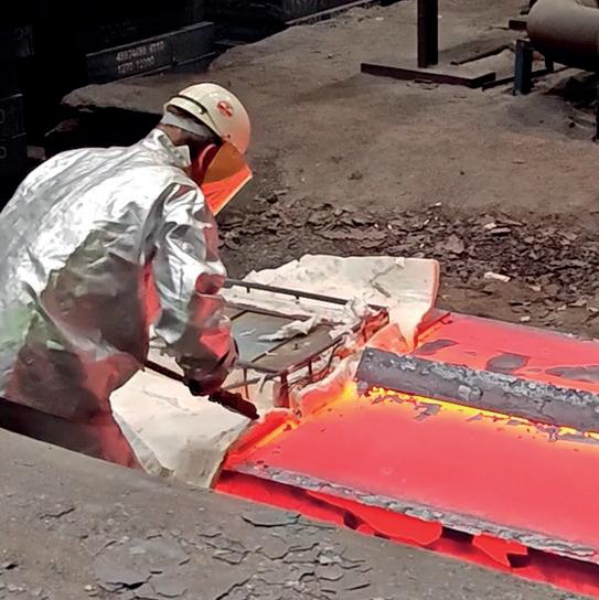

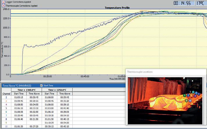


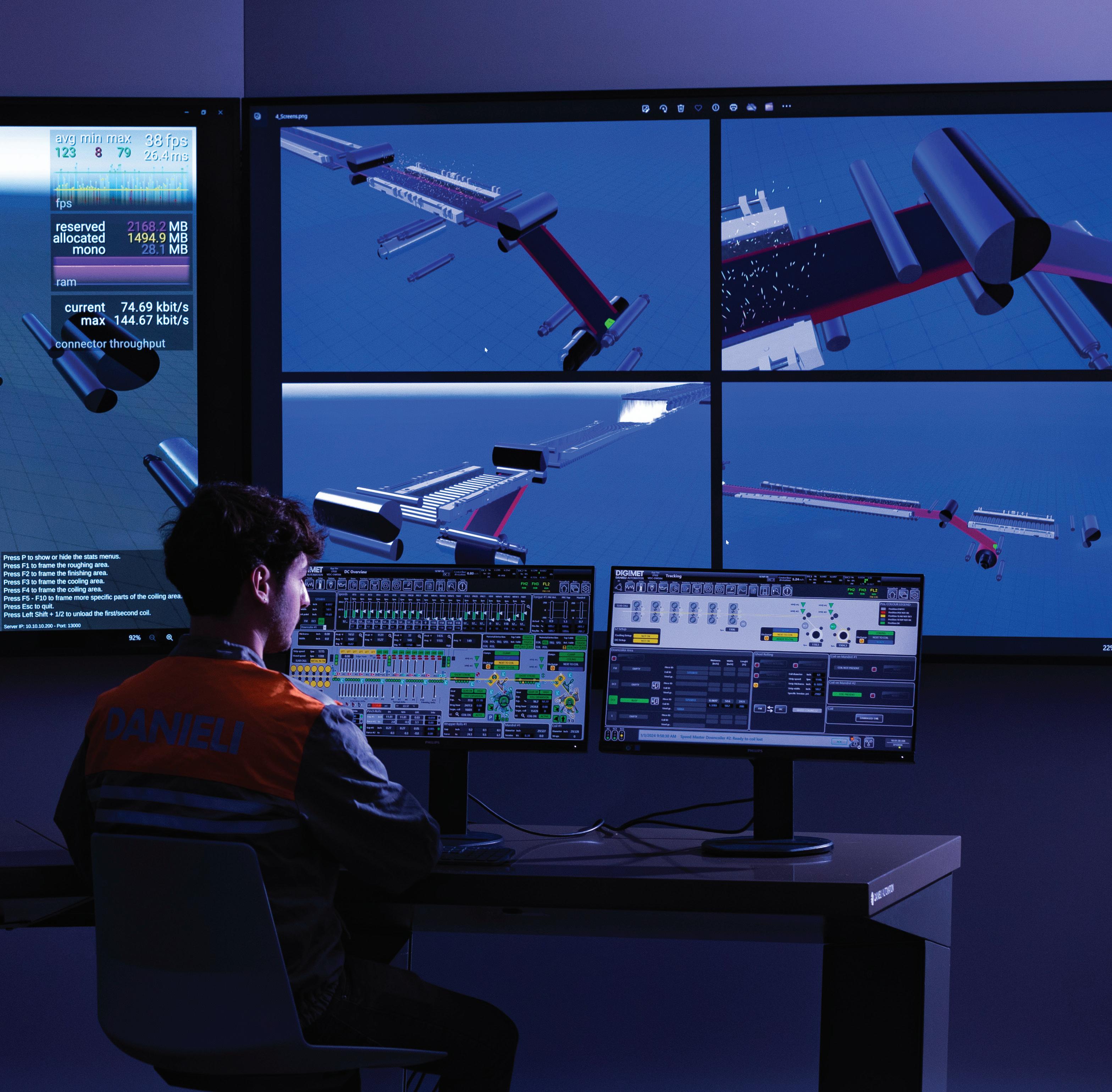
Modern, fully-automated plants are becoming more autonomous thanks to augmented reality, machine learning, generative artificial intelligence and digital twins. Danieli copilot guides operators in taking the best actions in unexpected events.