


INNOVATION AS STANDARD ® TOLEDO ENGINEERING / TECOGLAS / ZEDTEC / KTG ENGINEERING / KTG SYSTEMS / EAE TECH www.teco.com tc665_TECO_GlassIntl_Ad_Sep2022_v01.qxp_Layout 1 13/09/2022 15:37 Page 1 TECHNICAL SUPPLEMENT INDUSTRY 4.0 EXCLUSIVE INTERVIEWS SUSTAINABILITY www.furnaces-international.com - SEPTEMBER 2023


Temperature •Complete product temperature profile •Measure up to 20 points •No Trailing Thermocouples so quick, safe and cost effective •Custom systems to meet specific application challenges including Oil Quench! •Understand, control and improve your process TUS •Fully compliant to AMS2750 or CQI-9 •Live RF Telemetry TUS Data •Batch, Semi and Continuous Furnace Operation •Minimal Production Down Time •Quick easy TUS report generation Video •Inspect your furnace during live production •Find, fix and forget your furnace issues •Keep your furnace operational and productive . . . and Maintain ! Measure, Certify PhoenixTM GmbH Germany info@phoenixtm.de PhoenixTM Ltd UK sales@phoenixtm.com PhoenixTM LLC USA info@phoenixtm.com www.phoenixtm.com Visit us for more information: ... where experience counts ! Thru-process Temperature and Optical Monitoring
Editor: Nadine Bloxsome nadinebloxsome@quartzltd.com
Tel: +44 (0) 1737 855115
Assistant Editor: Zahra Awan
Tel: +44 (0) 1737 855038 zahraawan@quartltd.com

Production Editor: Annie Baker
Sales Manager/Advertisement
production: Esme Horn esmehorn@quartzltd.com
Tel: +44 (0) 1737 855136
Welcome to the September issue of Furnaces International.

With a number of important industry events taking place over the next few months, we thought it would be a great opportunity to print this issue and make it available to a wider audience.
Whether you are a regular reader of the digital version, or this is the first time you are reading a physical copy of the magazine, Furnaces International contains a digest of global news, events, and statistics as well as more detailed technical articles, company and country profiles, conference reports and regular regional economic briefings.
This issue is packed full of in-depth features from across the world of glass, aluminium and steel furnace technology. There is also a full review of the recent Furnace Solutions Conference, which took place in June and welcomed more than 120 glass industry professionals to also celebrate the opening of Glass Futures Global Centre of Excellence, a furnaces research centre in the UK.
I hope you enjoy this issue and whichever industry event you are reading it at!
Nadine Bloxsome, Editor, Furnaces International, nadinebloxsome@quartzltd.com

Subscriptions: Jack Homewood subscriptions@quartzltd.com
Managing Director: Tony Crinnion
1 Furnaces International September 2023
www.furnaces-international.com
Published by: Quartz Business Media Ltd, Quartz House, 20 Clarendon Road, Redhill, Surrey RH1 1QX, UK. Tel: +44 (0)1737 855000. Email: furnaces@quartzltd.com
Furnaces International is published quarterly and distributed worldwide digitally © Quartz Business Media Ltd, 2023 Front cover: TECO CONTENTS
www.furnaces-international.com
GREENER FURNACES 2 Greener Furnaces News 3 Enduring EAF optimisation technology plays a part in steel’s sustainable future GLOBAL FURNACES 6 Global Furnaces News 8 On-site hydrogen generation essential for Riverhawk company’s heat treat operations 12 Furnace Solutions LIFE OF A FURNACE 15 Life of a Furnace News 16 Overcoming the challenges of aluminium temperature measurements 19 Getting to the true core of the matter! 24 Assessing Boilerwatch® for potential benefits in glass manufacturing 28 Second steps of energy and CO2 reduction - use of Isotherms 31 New SMS reheating furnace at DanSteel for processing of thick continuously casted slabs
Verallia CEO: Decarbonisation projects remain on track
Glassmaker Verallia’s two key decarbonisation projects remain on schedule, said its CEO.
The company is developing two new technologies which will allow it to reduce its CO2 emissions.
Speaking to analysts during a financial call, CEO Patrice Lucas said the electrical furnace to be launched at its Cognac, France site is on track ready for next year.
The second technology is its hybrid furnace located in Zaragoza, Spain and start of production is scheduled for 2024.
He added two further decarbonisation solutions were also underway.
“Implementing our decarbonisation roadmap is also about being creative and being able to look at all the different solutions,” he said.
The Zaragoza plant has been using bio heating since 2022, meaning 20% of its natural gas has been replaced with bio heating, resulting in a 10% reduction in CO2 emissions.
This was a first pilot and will be implemented in all the divisions within Verallia.
The second project is what we call batch preheaters. It is about the use of batch heaters and the energy from fumes to heat raw materials before introduction into the furnace, which makes melting easier and less energy intensive.
The first application took place at its Bad Wurzach, Germany site at the beginning of 2023 with others planned in Portugal and Italy this year. This will reduce CO2 emissions by 12%.
Fives launches its first 100% hydrogen duct burner
Manufacturers are looking for alternatives to reduce their carbon footprint and since the combustion of hydrogen emits no CO2, it is one of the solutions to reduce their environmental footprint.
Always one innovation ahead thanks to its ability to anticipate customer needs, Fives has designed its first duct burner firing 100% hydrogen. Fives innovative solution, the Hy-Ductflam™, enables its customers to easily switch fuels going from 100% natural gas (NG) to 100% hydrogen (H2) without any changes made to the equipment.
Fives has announced the launch of its first 100% hydrogen duct burner. The Hy-Ductflam™ is a key step towards the decarbonization of heating and drying processes worldwide as hydrogen emits zero carbon when burnt. Designed for new installations or to replace standard duct burners, Fives’ solution can be easily implemented by manufacturers with very limited process modification.
Combining economic and environmental performance for customers
For example, by using Fives’ Hy-Ductflam™ set on 100% hydrogen, a paper plant will emit 170 kg less of CO2 per ton of paper produced which significantly reduces its carbon footprint (by about 2/3).
Providing high efficiency and mechanical reliability, the Hy-Ductflam™ is suitable for any duct configuration. This mean it can be installed both in new installations and as a replacement of standard duct burners thus limiting costs for manufacturers.
“Fives is at the forefront of hydrogen development and offers the largest range of hydrogen compatible burners on the market. We are proud to provide a new solution that answers the need for decarbonization of our customers and are exited for new innovations to come” declares Francesco Giudici, General Manager at Fives ITAS.
This technology is mainly dedicated to drying application in ceramic, minerals, pulp, etc. to name a few but could be extended to other applications such as heat recovery boilers.
NEWS GREENER FURNACES 2 Furnaces International September 2023 www.furnaces-international.com
Enduring EAF optimisation technology plays a part in steel’s sustainable future
Zahra Awan* spoke with Frederik Esterhuizen** and Zaeim Mehraban** from ABB on the latest developments in electromagnetic stirring (EMS) technology and its benefits for the steelmaking industry. EMS is not a new technology, since it was first patented around 80 years ago [2], but as Furnaces International found out, ongoing advances mean it remains highly relevant today.
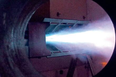
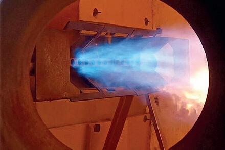
Electromagnetic stirring on the world’s most productive Electric Arc Furnace (EAF) with Tenova and ABB at Acciaieria Arvedi, Italy
COULD YOU GIVE A BRIEF HISTORY ON ABB AND ITS ROLE IN THE METALS INDUSTRY?
Frederik Esterhuizen (FE): ABB is a global technology with more than 130 years of history across industries, providing everything from the smallest electrical components to large motors and drives, powering mines, trains, paper mills and even cruise ships. In the metals industry, ABB leads the way in electrification and automation for our customers, enabling a more sustainable and resource-efficient future. The company’s solutions, incorporating specific metallurgy products and digital, connect engineering know-how and software to optimise how things are manufactured, moved, powered, and operated.[1]
Zaeim Mehraban (ZM): ABB has been a leading supplier and a trusted partner for the metals industry for many decades, collaborating with steelmakers, producers, original equipment manufacturers (OEMs) and other suppliers to develop customer-specific solutions to increase productivity, efficiencies, quality, and safety, while also driving the transition towards more autonomous plants.

GREENER FURNACE 3 Furnaces International September 2023 www.furnaces-international.com
* Assistant Editor, Furnaces International
** Global Business Line Manager, Metals, ABB
*** Global Sales Manager, Metallurgy Products at ABB (on EAF)
Zaeim Mehraban
WHAT IS THE ROLE OF AN EAF IN THE FUTURE OF THE STEEL INDUSTRY?
ZM: The EAF is expected to play a significant role in the future of the steel industry due to its flexibility, lower carbon emissions, resource efficiency, adaptability, and recycling capabilities. As the industry continues to pursue sustainable and low-carbon steel production, EAF technology will continue to evolve and contribute to the advancement of the steelmaking processes.
EAFs offer more possibilities when compared with traditional blast furnaces. They can efficiently process a wide range of raw materials, including scrap steel, direct-reduced iron (DRI), and hot metal, allowing for a more diverse feedstock. This enables steel producers to respond quickly to market demands and changing availability of raw materials. Crucially, they have a lower carbon footprint compared to blast furnaces and can be powered by renewable energy sources, further reducing their environmental impact and contributing to the transition towards green steelmaking.
EAFs can serve as a platform for integrating emerging technologies and processes in steelmaking. As the industry progresses towards carbon-neutral steel production, they can be modified and optimised to accommodate innovations such as direct electrolysis, carbon capture and storage, and other breakthrough technologies. This adaptability positions EAFs as a key component in the steel industry’s transition towards a more sustainable future.
FE: There is traditionally a lot of carbon in the steelmaking process, which is where the EAF comes in. It reduces the carbon content significantly. Customers are also testing their electrical furnaces with different configurations, beyond standard methods, to help achieve sustainability targets around the globe. Movement towards electric options vary depending on geographical region and legislative objectives set, but meeting sustainability targets is in the minds of industry operators and management teams.
WHAT ROLE DOES AN EMS PLAY IN THE EAF?
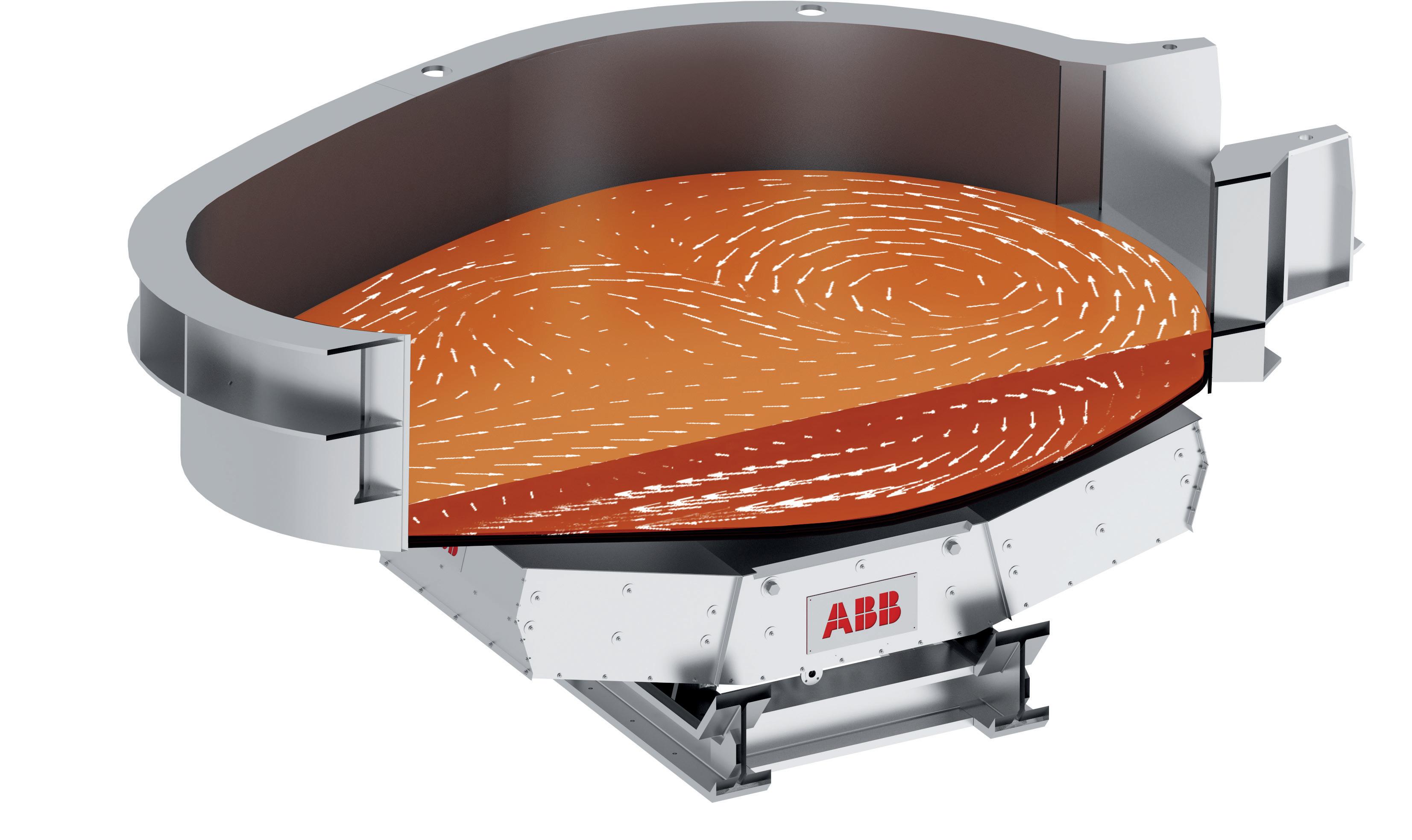
ZM: EMS is not a new technology: it was first patented by ABB about 80 years ago [2] , but it has evolved. Electromagnetic stirrers (EMS) play a significant role in the operation of an EAF by improving the mixing and homogenisation of the molten metal. The primary function is to induce fluid flow and agitation within the metal bath. By generating a magnetic field that interacts with the conductive molten metal, EMS promotes circulation to homogenise the temperature and composition and ensure more uniform steel.
The stirring effect created by EMS enhances heat transfer within the molten metal. This improved heat transfer allows for faster melting of scrap steel and other raw materials in the EAF, leading to increased productivity and shorter processing times. It also aids in maintaining a consistent and uniform temperature within the furnace.
The agitation provided by EMS facilitates chemical reactions between slag and metal while also improving the mixing of additives and alloying materials. By this way EMS enhances iron yield and solves the bottom skull problem.
The improved heat transfer and mixing effect of EMS, ensure the rapid homogenisation of temperature and composition throughout the molten metal bath. This uniformity allows for more precise, efficient control of the steelmaking process, resulting in a more consistent and repeatable process.
By fulfilling these roles, EMS contributes to the overall efficiency, quality, and consistency of steel production in an EAF. It helps steelmakers achieve better control of the EAF processes, improve efficiency and productivity. According to our research, typical benefits based on 160+ ArcSave electromagnetic stirrer installations worldwide include 5-7% increase in productivity, 3-5% reduction in energy consumption and related carbon emissions, up to 1% higher yield and lower use of alloys, lime and other process additions.
INSTALLATIONS EAF-EMS TECHNOLOGY [2]
ABB has 165+ EAF-EMS technology installations globally including 149 first generation. According to ABB, steelmakers who have installed or will install ArcSave, the latest generation of this technology, representing all furnace types – carbon steel, stainless/specialist and Consteerer™ include:
� Steel Dynamics Inc., Roanoke, USA, 2014, on a 90 tonne EAF for carbon steel production.
� Outokumpu Stainless AB, Avesta, Sweden, 2014, on a 90 tonne EAF for stainless steel production.
� POSCO, Pohang, South Korea, 2018, on a 95 tonne EAF for stainless steel production.
� SeAH Changwon Integrated Special Steel, Chang-Won, South Korea, 2018, on a 70 tonne EAF for stainless steel and tooling steel production.
� Yongfeng Steel, Shandong, China, 2019, on two 160 tonne Consteel™ furnaces for carbon steel production.
� Böhler Edelstahl, Kapfenberg, Austria, 2020, on a 50 tonne EAF for special steel production.
� Nippon Yakin, Kawasaki City, Japan, 2021, on a 70 tonne EAF for special steel production.
All information from this box has been sourced from source 2.
GREENER FURNACE 4 Furnaces International September 2023
HOW DOES USING AN EMS BENEFIT THE PRODUCTION OF STEEL REGARDING ECONOMICS, EFFICIENCY, SAFETY AND THE ENVIRONMENT?
ZM: EMS helps reduce the environmental impact of steel production by improving energy efficiency and reducing carbon emissions. The enhanced mixing and heat transfer facilitated by EMS can lead to shorter processing times and lower energy consumption. Use of alloys, other process additions as well as electrodes and refractory materials is also reduced using EMS, further contributed to resource efficiency and lowering overall environmental impact. Additionally, when combined with the use of renewable energy sources, EMS contributes to the reduction of greenhouse gas emissions and helps achieve sustainable steel production.
EAF-EMS has a measurable impact on furnace productivity. At Steel Dynamics, for example, productivity increased by 6%; at Outokumpu Stainless by 6-8%; and at SeAH, the increase was 5-7%. There is also an increase in yield, typically by about 1%. [2]
The agitation and improved heat transfer provided by EMS result in faster melting of scrap steel and other raw materials in the EAF. This leads to increased productivity, shorter processing times, and higher overall efficiency in steelmaking operations. EMS ensures the homogenisation of temperature and composition throughout the molten metal bath. This uniformity allows for more precise control over the steelmaking process, resulting in consistent and high-quality steel products.
The faster melting and processing enabled by EMS contribute to higher production rates and increased throughput. This enhanced productivity can positively impact the economics of steel production by reducing costs per ton of steel produced.
Steelmakers with EAF-EMS are able to maintain greater control of costs. Critically, energy costs are reduced, as power-on time is shorter and complete melting is achieved more efficiently. Energy consumption fell by 5% at Steel Dynamics, and by 3-4% at both Outokumpu Stainless and SeAH. These energy savings are inclusive of the energy used by the stirrer, which is roughly 2-3kWh per tonne of liquid steel. [2] The use of EMS can improve safety in steelmaking operations. By enhancing the mixing of the molten metal, EMS reduces the likelihood of stratification, which can lead to localised overheating and potential accidents.
WHAT WAS LEARNT FROM THE IMPLEMENTATION OF AN EMS IN ACCIAIERIA ARVEDI’S EAF IN ITALY?
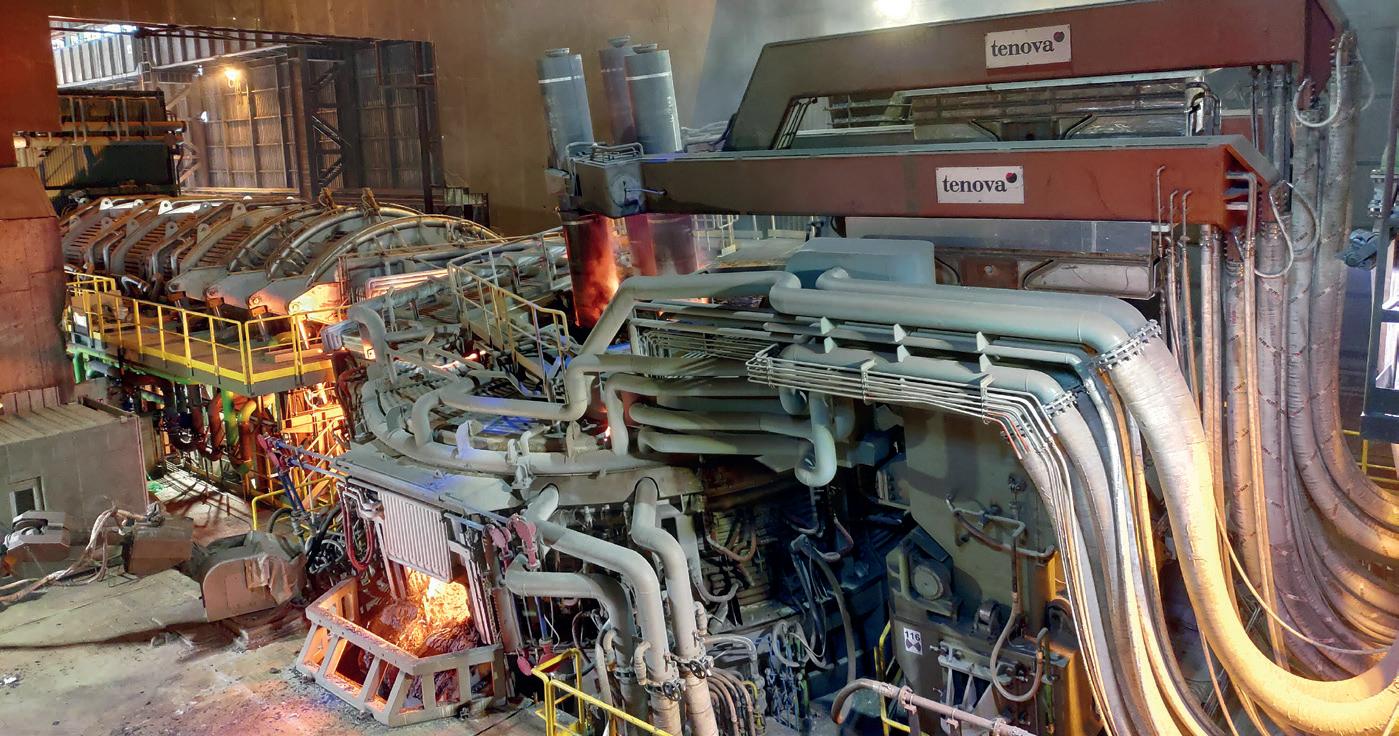
ABB partnered with Tenova for their customer Acciaieria Arvedi in Cremona, Italy, to meet demand for higher productivity and increased electrical energy efficiency of the recently improved endless strip production (ESP) line. Acciaieria Arvedi placed an order in 2018 for a new 450ton Tenova Consteel® electric arc furnace (EAF) to replace the existing 350-ton Consteel® EAF. ABB Metallurgy supported this project with the EAF-EMS application known as Consteerrer®, which was co-developed with Tenova.
ZM: The Acciaieria Arvedi furnace is a jumbo furnace. It is a type of furnace that did not exist before. We have learned much more about the benefits EMS can bring to these large furnaces, improving the process, productivity and also removing the pervasive bottom skull problem for steelmakers.
HYDROGEN HAS BECOME THE MAIN BUZZWORD IN THE LAST FEW MONTHS, IN INDUSTRY. CLOSING THE INTERVIEW: WHAT IS YOUR ABB’S POSITION ON HYDROGEN FUEL?
FE: As a fuel, hydrogen is one possible solution and can be the right move for many industries. There are many challenges to its roll-out, including current high costs, transportation and infrastructure.
ABB is part of the hydrogen business. We have a company in Sweden who we are collaborating with on a pilot project to see how hydrogen can then be further optimised, developed and scaled. One of the biggest challenges for hydrogen is making it scalable. Hydrogen doesn’t counter all the challenges we have, but a key benefit is that it helps with carbon neutrality. We can look forward to a future where hydrogen is very much part of the mix.
WHAT ABB LEARNT FROM THE ACCIAIERIA ARVEDI PROJECT [3]
As a part of the Acciaieria Arvedi project, we have learned that the stirring power has a clear effect on stirring efficiency. The higher the EMS power, the higher the stirring efficiency. Apart from improving furnace performance, Consteerrer® will improve the EAF process and reduce its carbon footprint. The key takeaways from the project are given below:
� Temperature homogenisation time is considerably longer at 447 seconds with 5% EMS and only 113 seconds with 100% EMS
� The temperature gradient between the furnace bottom and the surface during arc power-on is reduced from 114oC with 5% of EMS power to 26oC with 100% EMS
� The heat flux transferred to the scrap increases with increased EMS stirring power. The average heat flux transferred to the scrap with 100% EMS is 2.7 times higher than that with 5% EMS
� Consteerrer® stirring improves heat and mass transfer in the EAF process and also reduces energy and electrode consumption, besides increasing productivity.
� The guaranteed KPIs with EMS are fully achieved in the new Consteel® furnace project
All information in this box has been sourced from source 3.
LINKS:[1] https://global.abb/group/en/about/our-purpose [2] https://new.abb.com/metals/abb-in-metals/references/electromagnetic-stirring-andelectric-arc-furnaces [3] https://new.abb.com/metals/insights/electromagnetic-stirringtechnology-for-450t-consteel-furnace
GREENER FURNACE 5 Furnaces International September 2023 www.furnaces-international.com
Sorg secures Chinese glass furnace order

Sorg has secured a furnace order from China’s Nanjing Electric.
In 2014, Sorg received the first order for the delivery of a regenerative endport furnace with a working end and two forehearths for the manufacture of such insulators.
The insulators produced by Nanjing are subject to a tight glass chemistry specification, which is different for direct current (DC) and alternating current (AC) insulators.
With an article weight of up to 12kg, extreme demands are placed on the glass in terms of glass homogeneity, melting relics, and inclusions from unmolten batch particles and seeds.
The first furnace delivered by Sorg exceeded the requirements regarding the factors mentioned above and the operating time.
Nanjing Electric has commissioned Sorg to deliver a further system.
To comply with the Chinese government’s new emission regulations, a VSM type all-electric melter was supplied.
Sorg reports that the customer was
BlueScope Steel to reline Port Kembla blast furnace
BlueScope Steel has approved the relining of its dormant number six coal-fired blast furnace, which will be the most expensive infrastructure project in the company’s history.
Responding to criticism, the company has said that the decision to reline the furnace will not lock the company to coal-based steelmaking for the next two decades.
The project was initially estimated to cost between $700 million and $1 billion, however the steelmaker has updated the cost to about $1.15 billion.
Following pressure to abandon the reline due to the heavy environmental impacts of blast furnaces, chief executive Mark Vassella confirmed: “There are not technologies which are commercially viable to replace the blast furnace so, we are building a bridge to the future. This allows us to continue to grow and generate the profits that will allow us to invest in the newer technologies, the lower emissions steelmaking technologies as they emerge.”
The new blast furnace would have a ‘campaign life’ of 20 years, however, Vassella said it did not mean BlueScope was committed to using coal to make steel for the full period.
“We have set a net-zero goal but have been really clear that what we need in Australia to support that are enablers around renewable energy, hydrogen, raw materials.”
NEWS GLOBAL FURNACE 6 Furnaces International September 2023 www.furnaces-international.com
highly satisfied with the technology and emphasised the outstanding service and support.
In a gracious ceremony, some of the Sorg employees were made honorary members of the Nanjing Electric company.
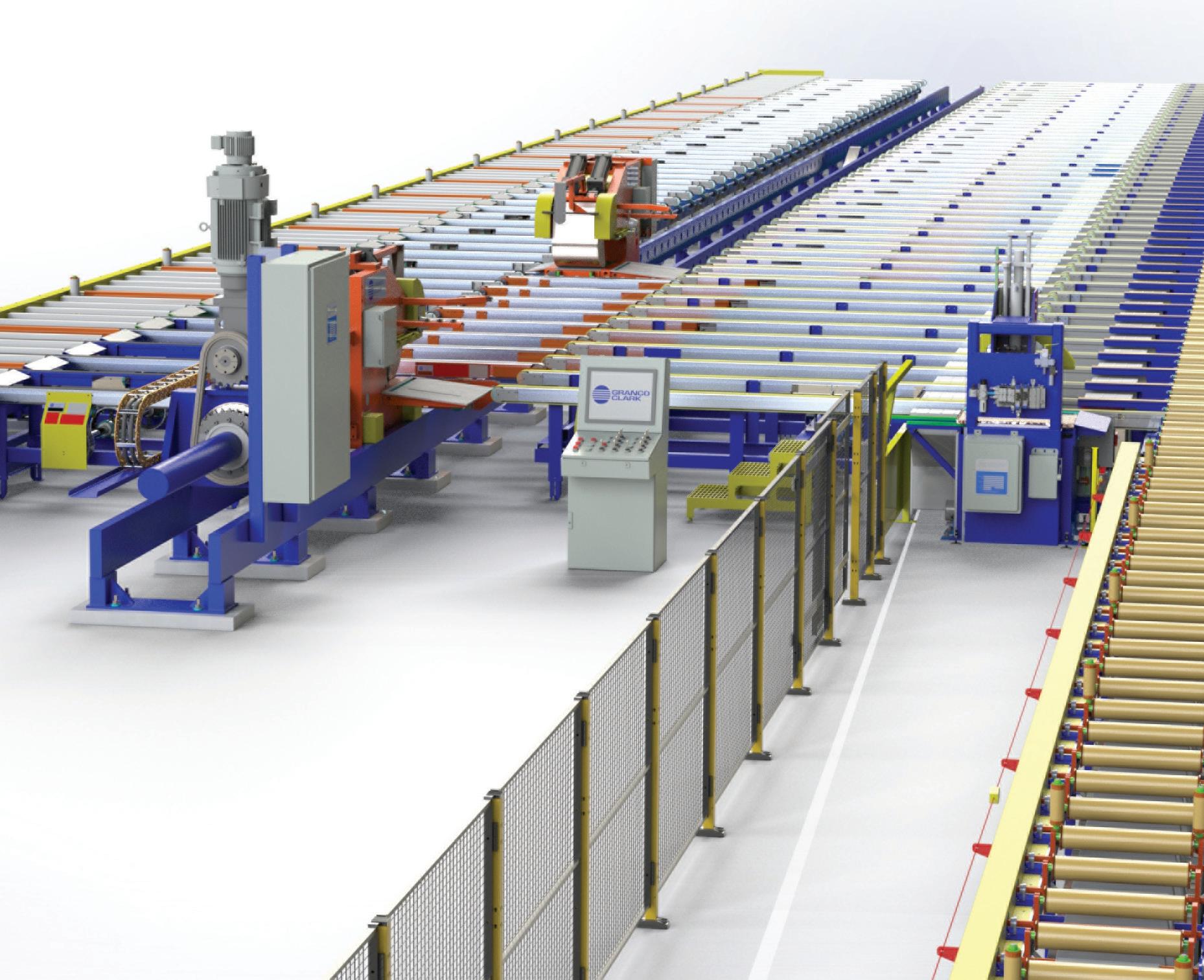


Engineering. Manufacturing. Global Support. Excellence is our standard. 100% Employee-owned Contact us to discuss your next project. +1-800-918-2600 | www.grancoclark.com We are 100% customer focused. GRANCO CLARK, a global leader in the aluminum extrusion industry building a full range of aluminum extrusion equipment including some of the world’s largest aluminum extrusion systems. GRANCO CLARK produces all required equipment to heat, cool, pull, stretch, cut, stack, age, and store aluminum extrusions. Leading in the optimization of extrusion technologies and processes, our automated equipment is designed, fully assembled and shop tested to the specific requirements of your extrusion process to deliver exceptional efficiency, productivity and longevity. Contact us to discuss your next project.
On-site hydrogen generation essential for Riverhawk company’s heat treat operations
 By Marie Pompili*
This article has been provided by Heat Treat Today

For heat treat operations, use of hydrogen comes with questions about price-point, safety, and storage or delivery. Read this case study to learn how a manufacturer with in-house heat treat, Riverhawk Company, contended with these questions and decided to meet stringent production requirements for pivot bearings by leveraging on-site hydrogen and a hydrogen furnace.
For companies using hydrogen furnaces for heat treating operations, questions always surface surrounding the provision of the necessary hydrogen. Should we have it delivered in cylinders? Do we have the room outdoors for a large storage tank? Can we generate it ourselves? For Randy Gorman, maintenance supervisor at Riverhawk Company, the overriding question is always, “How do we handle hydrogen safely?” The ultimate solution the company chose was the installation of an on-site hydrogen generator. How and why the in-house heat treater came to that conclusion is an interesting story.
Making a History
Located in New Hartford, NY, USA, Riverhawk Company was established in 1993 as a value-added provider of hydraulic tooling. The company quickly grew from a “buy and assemble” operation to a manufacturer with 14 CNC machine tools, 21 conventional machines, and all the necessary peripheral devices, tools, and software. Through a period of smart acquisitions and the development of new product lines, Riverhawk became one of the leading manufacturers of tensioners, powertrain couplings, and accessories for the turbomachinery industry; the instrumentation product line of legacy torque and vibrations measuring instruments; and the Free-Flex® pivot bearings, which
GLOBAL FURNACES 8
Furnaces International September 2023 www.furnaces-international.com
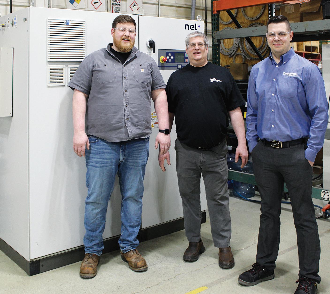
Riverhawk staff (L to R): Spencer Roose, Flex Pivots Manager; Randy Gorman, Maintenance Supervisor; and Josh Suppa, Pivot Department Engineer
*Freelance Writer
are very well known in high performance industry sectors.
Pivot Bearing Line Requires Improved Heat Treat Abilities
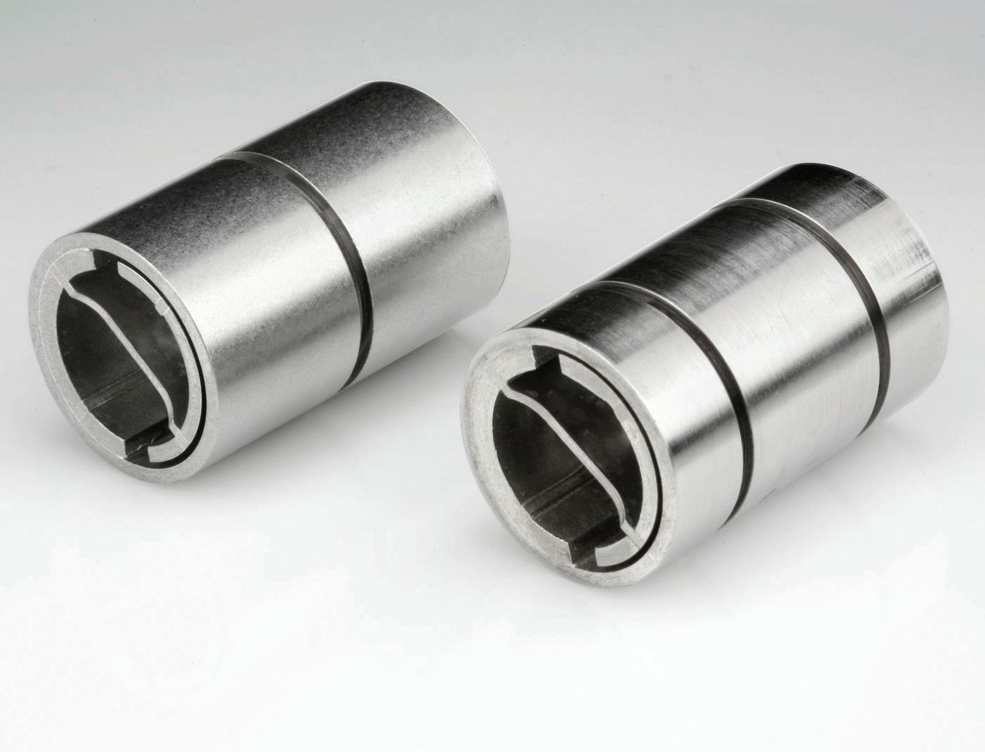
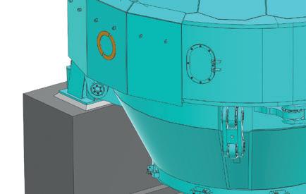
The Free-Flex® pivot bearing line is the focus in this heat treat/hydrogen story. Riverhawk purchased this line from Goodrich in 2004. It is the same product that was developed by Bendix more than 60 years ago. In fact, many of the original part numbers are the same, and the manufacturer strives to maintain the quality and performance characteristics that Bendix established more than six decades ago. Many of the manufacturer’s clients have been purchasing flex pivots for long-running applications, some of which are 25 to 50 years old. Figure 1
If a product line could talk, the flex pivots could share some tales and compelling accounts about all it has seen and done in the world’s most critical and sophisticated applications — many in the military, commercial aerospace, outer space, industrial robotics, medical, clean rooms, information technology, semiconductors, and many more. In all of these challenging sectors, clients are wellknown and demand exacting results.
Shortly after integrating the pivot line into its existing production processes, it became clear that the company needed to improve its heat treat function. After researching several options, Riverhawk purchased a new Camco batch hydrogen furnace.
The pivot line consists of flat springs crossed at 90° and supporting cylindrical counter-rotating sleeves. Standard FreeFlex® pivots are made from 410 and 420 stainless steel; however, certain special material compositions include 455 stainless, Inconel 718, titanium, and maraging steel. During the manufacturing process for the flexure bearings, Riverhawk uses the batch atmosphere heat treat furnace to braze the springs to the body halves using a braze alloy, and to simultaneously heat treat certain components in the assembly. The atmosphere used for the heat treating and brazing is a 100% hydrogen atmosphere — chosen because it is universally applicable to all the different metallurgy used for the flex pivots.
The Tension: Delivered vs. On-site Hydrogen?
The use of a batch atmosphere heat treat furnace requires that the hydrogen
atmosphere be flushed from the furnace with inert nitrogen when a finished batch is unloaded and a new load is added. Likewise, the furnace must return to inert atmosphere again with nitrogen after the new load is added, and before hydrogen is again injected; hence, hydrogen is used in a batch-wise fashion. The function of the hydrogen atmosphere is to prevent oxidation of the metal surfaces, and to promote fluxing of the braze alloy during the thermal cycle.
Until 2009, Riverhawk used hydrogen-filled cylinders to provide hydrogen to their batch heat treat furnace. Each run of the furnace would use several cylinders of hydrogen. Increases in production rates required careful management of hydrogen gas supply to the furnace. Running out of hydrogen mid-run could sacrifice a whole batch of nearly completed parts.
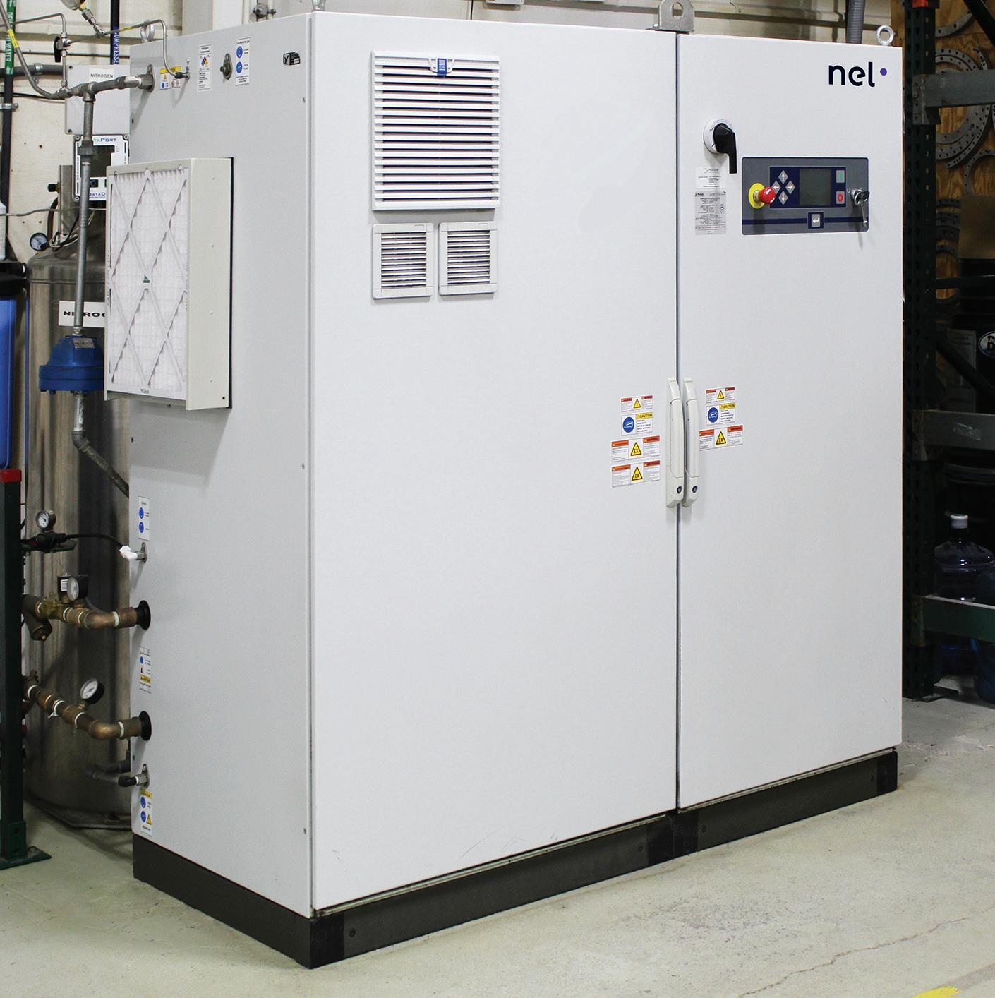
In 2009, the company elected to move away from hydrogen cylinders and transition to a hydrogen supply approach less disruptive to their production process. The choices were either bulk stored hydrogen or on-site hydrogen generation. After extensive consideration, they chose a model H2 hydrogen generator from Nel Hydrogen because the zero-inventory hydrogen generation saved the company money as compared to the cost of permitting, construction, and compliance for bulk stored hydrogen approaches.
The approach that was not chosen — delivered, stored bulk hydrogen — was unappealing for several reasons. Chief among these were the capital cost of the hydrogen storage infrastructure, the requirement for permitting for the necessary hydrogen storage, the accompanying project schedule risk for permitting, the continuous compliance issues with stored
hydrogen, and the price volatility of delivered hydrogen that would have made cost accounting more difficult.
“The state and local regulations were likely necessary; however, there was a lot to wade through to become compliant,” said Gorman.
Finding the Best Way
Fast forward 14 years to today and Riverhawk is once again analysing its approach to handling its hydrogen requirement.
“The H2 model generator that we have has served us well for 14 years, several years beyond the typical life of a cell stack,” said Gorman. “But we need more capacity and redundancy due to the increased demand for our Free-Flex® products and to cost-effectively mitigate the risk of a hydrogen generator issue, leaving us without the use of our furnace.”
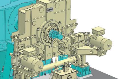
The company decided to go with a model H4 hydrogen generator from Nel Hydrogen, which doubles their capacity with two cell stacks and the capacity for three if and when needed. The new system features the same footprint as the former H2 model, which is important to them, and they are even gaining floor space as they will eliminate the number of cylinders formerly stored nearby. The additional free space to move about also appeals to Gorman’s top mandate for safety. Figure 2
Josh Suppa — engineer of the Pivot Department at Riverhawk — has had hands-on experience with this particular generator series (pictured on page 16).
“The maintenance of it is easy, and if there ever is a rare issue, Nel is quick to respond either in person or if it’s something that they can walk us through, they take all the time we need to resolve the matter and get us back online quick-
GLOBAL FURNACES 9 Furnaces International September 2023 www.furnaces-international.com
Figure 1. Cantilevered-double ended thick spring. Riverhawk purchased the Free-Flex® pivot bearing line from Goodrich. Many of the company’s clients, in a wide range of critical industries, have been purchasing flex pivots for long-running applications.
ly. From a product line and customer satisfaction perspective, we cannot take the risk of our heat treat operation to go down for long. It’s that integral to our success. It’s essential, really, and one of our core competencies.”

Choosing On-Site Hydrogen Generation
Looking back on the initial decision to generate on site, one of the important issues that Riverhawk and Nel personnel had to determine was the most cost-effective configuration of the hydrogen generator and ancillaries to supply the hydrogen required for thermal processing. Had the manufacturer used a continuous furnace such as a belt furnace, then the calculations would have been easy, as the flow rate required would have been level and continuous. Instead, the batch furnace required more complex calculation because the hydrogen flow rate varies depending on the stage of the furnace cycle: fast hydrogen flow to fill the furnace, then slow to maintain the atmosphere, then no flow during parts removal and during loading. Additionally, there were many factors that affected the precise furnace cycles employed, including the size of the pivots in each batch, the number of parts loaded, and the specific metallurgy of the flex pivots in the batch. Overall, the cycle times can vary between 6 and 12 hours per batch.
It is important to seek out a knowledgeable hydrogen partner in this endeavor to specify exactly what’s needed, no more and no less. For heat treat applications, users generally would want compact equipment, extreme hydrogen purity, load following, near-instant on and instant off, and considerable hydrogen pressure that make it flexibly suited for a variety of thermal processes.
By combining on-site hydrogen generation with a small amount of in-process hydrogen surge storage if needed, on-site hydrogen generation can be used to meet the needs of batch processes, such as batch furnaces. By carefully choosing generation rate and pressure, and surge storage vessel volume, the process can provide maximum process flexibility while minimising the amount of hydrogen actually stored.
In practice, client priorities such as minimum hydrogen storage, or lowest system capital cost, or highest degree of expandability, or least amount of space
occupied can be met by choosing the specific hydrogen generator capacity and surge storage system employed for any particular production challenge.
In this case study, the optimum solution chosen was based on lowest capital cost and operating cost (including maintenance) while preserving the maximum possible expandability for production increases, and safety. These sound like common reasons and may be yours as well. Success continues at Riverhawk with the arrival of the new H4 generator in the coming weeks. �
For more information: Visit nelhydrogen.com and www.riverhawk.com.
GLOBAL FURNACES 10 Furnaces International September 2023 www.furnaces-international.com
Figure 2. Riverhawk will soon use a model H4 hydrogen generator from Nel Hydrogen, which doubles their capacity with two cell stacks and the capacity for three if and when needed. The new system features the same footprint as the former H2 (pictured here).
(Photo Source: Nel Hydrogen)


GLASS SERVICE Tying Technology Together Help the planet existing chnology educe CO2 with: l Boost l More boost l Electric forehearth l Superboost l Hybrid ur naces ble future from Glass Service and FIC The World,s Number One in Fur nace Technology FIC (UK) Limited Long Rock Industrial Estate, Penzance, Cornwall TR20 8HX, United Kingdom www.fic-uk.com +44 (0) 1736 366 962
Furnace Solutions
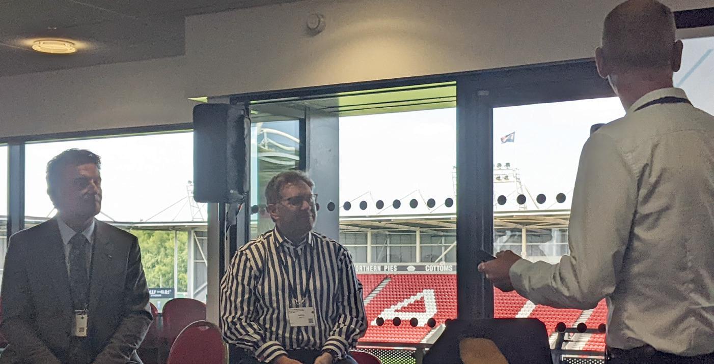
The 17th Furnace Solutions conference explored the route to sustainable production, for the glass and furnace industry, despite the challenges faced by the industries. It was noted that throughout the years, the conference agenda has dramatically changed. Attention and awareness on the actions, and consequences of production, and the importance of sustainability, is now a key topic of conversation. It was also observed that although the industry has made drastic changes, a push to decarbonise is required to ensure the industry is a role model to all heavy manufacturing industries.
The Furnace Solutions Conference hosted over 120 glass industry professionals in St. Helens, a historic town with a deep connection to industry. Zahra Awan* reports on the conference.

“We hope that we will see future developments and commitments to improving sustainable production” – Arun Varshneya, President of the Society of Glass Technology and CEO and President of Saxon Glass Technologies.
Glass Futures
The event was hosted in conjunction with the opening of Glass Futures Global Centre of Excellence, a furnaces research centre.
On the occasion, Aston Fuller, Glass Futures General Manager, said: “This opening marks a new chapter for Glass Futures with St Helens as our home. A key part of that for us is working with as many local partners as possible, supporting local businesses, creating jobs, and attracting new companies and start-ups to come and join us in the borough.”
Richard Katz, CEO, Glass Futures added: “Removing carbon emissions from global manufacturing is our world’s greatest challenge, and we need to change how we do things.” With this, Furnaces Solutions followed with a two- day conference, including 14 presentations from various global companies.
The Conference
“The technology used in producing glass has not changed for centuries. What has changed, however, is how we use that technology.” – Attendee of Furnaces Solutions
*Assistant Editor, Furnaces International
The presentations included discussions on sustainable solutions, and new technology: Debates on the best way to transition to net zero continued, but a focus on
GLOBAL FURNACES 12
Furnaces International September 2023 www.furnaces-international.com
electric and hybrid melting made an appearance, as well as the potential implementation of hydrogen fuel, alternative raw materials, and sustainable refractory development.
Policies and Government
“I wish we could have more significant support and investment and money from the government to help decarbonisation.”
– Attendee of Furnaces Solutions
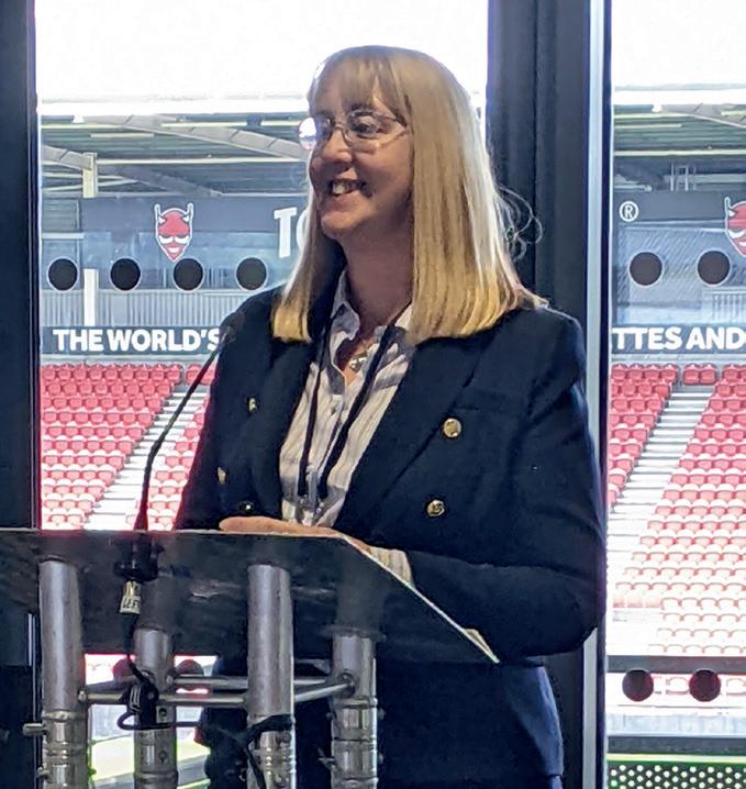
Opening the conference, Jenni McDonnell (MBE), Thermal Energy Specialist at Innovate UK, discussed the Industrial Energy Transformation Fund (ITEF). Over the years, the fund has allocated £315 million in assisting the industry with the financial burden of decarbonisation and has funded over 130 projects since April 2020. Ms McDonnell announced that the fund is due to return in 2024 with an additional £185 million.
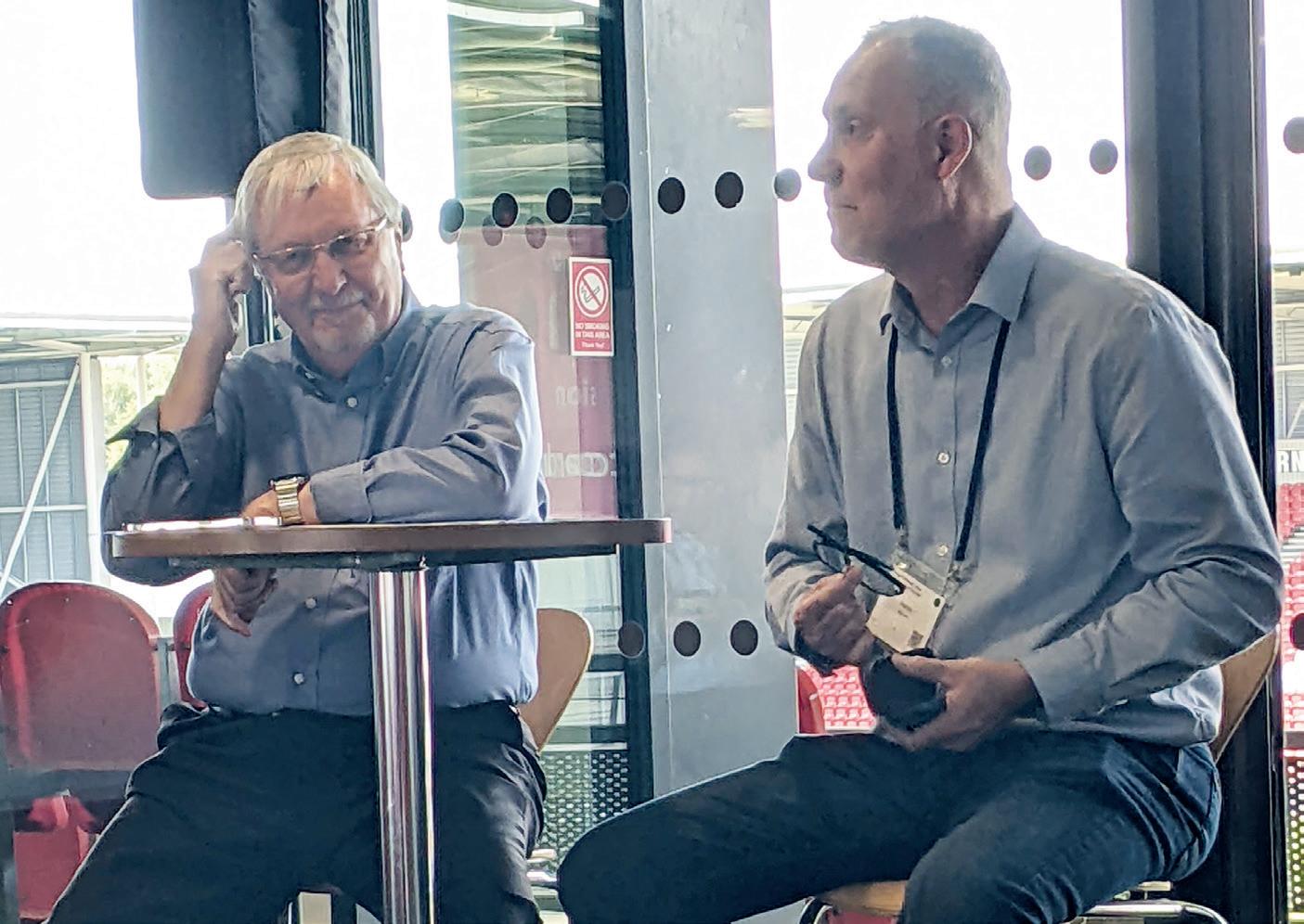
Later, a debate between Matthew Demmon, Managing Director, MKD32, Steve Whettingsteel, CEO, Krystelline Technologies, and Nick Kirk, Technical Director, Glass Technology Services noted the significant losses that the glass industry faces, and methods to combat this. In the debate, the three discussed their view on cullet, and recycled glass.
“Globally 50 million tonnes of glass is lost annually”; “glass is infinitely recyclable with no loss of quality, … All glass can and should go back to remelt to produce new bottles”
- Steve Whettingsteel, CEO, Krystelline Technologies
Mr Demmon concluded that the export of cullet was encouraged by the Producer Responsibility system, which in turn, deprives the UK of recycled glass and therefore, a circular economy. Dr Kirk related to this conclusion in his findings: Cullet export was up 30% in 2022, and UK remelt decreased by 48,000 tonnes in the same year. To tackle this challenge, the Extended Producer Responsibility (EPR) strategy is said to be put in place, starting from 2025 in the UK.[1]
The Extended Producer Responsibility (EPR) is a policy tool that extends the producer’s financial and/or operational responsibility for a product to include the management of the post-consumer stage, in order to help meet national or EU recycling and recovery targets. EPR policies thus generally shift the waste management cost
or physical collection partially or fully from local governments to producers [2]
This strategy aims to hand over the responsibility of accounting for waste to producers, or local governments, giving them more autonomy over the systems in place for recycling, relying on their desire to enhance and evolve recycling programs. Mr Demmon stated that “between now and 2030, the EPR is expected to increase glass collection by 350 KT, by drawing cullet out of IBA (Incinerator bottom ash) and landfill. As well as increase remelt by 400 KT.”
Steve Whettingsteel raised his concerns to the conference with regards to the effectiveness of the EPR and cullet recycling. The circularity of glass is key to furthering its decarbonisation. Mr Whettingsteel suggested that rather than resorting to optical sorting for landfill and cullet, a revolution to sorting ands and powder productions should be made. His concepted aimed at converting “all incoming glass int high valuable alternatives.” Which could then be used in new developing markets.
With this suggestion, it became apparent that although the EPR provides a solution to one of the many challenges
that are faced when tackling decarbonisation, there are still many routes that can, and could be taken to assist in the industries transition to net zero. It raised the question: how should the industry adapt to unique situations, should they invest in multiple strategies, or do we attempt to all fit into one box?
Digitalisation and New Technologies
With the digitalisation of an industry which has seen centuries of development, it is only natural that there are challenges that come with this progression, as well as tremendous benefits. However, the glass industry is no luddite.
Burcin Gul Arslanoglu, Executive Senior Researcher, ŞiŞecam spoke on ‘pushing the limits of production in float furnaces’. With the prediction of a high growth in demand for global float glass Ms Arslanoglu discussed the benefits of implementing digital solutions into furnaces, namely the use of computational fluid dynamics (CFD) modelling. She noted the importance of modelling with regards to testing possible solutions to experiment the limits of the technology we currently have.
The software could be used to explore different parameters within the furnace, such as adding more cooling nozzles, velocity, flow rate and exhaust location. Using the knowledge from the tests, she believed that CFD can help develop roadmaps for the next 50 years. In her closing notes, Ms Arslanoglu concluded that the biggest challenge is the conflict between increasing capacity at the same time as reducing emissions.
The conference hosted a range of key players and experts in the field of furnaces. With this, a range of opinions circulated. One conflict of opinion questioned whether a longer life furnaces better despite times of rapid change?
GLOBAL FURNACES 13 www.furnaces-international.com
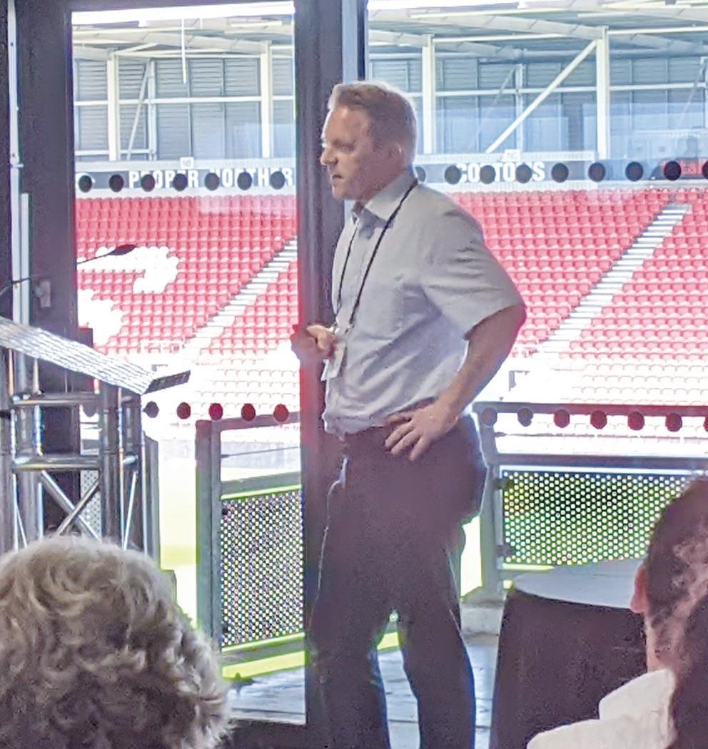
Burcin Gul Arslanoglu made her opinion clear that the life of a furnace should be improved and made longer. In contract, Stuart Hakes, FIC, stated: “We must moveout of these long-life furnaces, so we do not lock ourselves in with a set of technology.” He was supported by Andrew Reynolds, Fives, who said that long-life furnaces aren’t necessarily the solution to the industry’s problems.
With this in mind, what is the solution, and how do we find it?
Glass Futures representative Dr. Sebastian Woltz, Sales Director, EME discussed the importance of conceptual engineering with regards to new furnaces, and how it should be used to continue to adapt and develop existing furnaces, to make way for new technology and ideas. Later it was suggested by Stuart Hakes, Chief Executive at FIC, and Andrew Reynolds, Business Development Director at Fives, that electric furnaces were the answer to effective yet adaptable furnaces.
Carbon Capture and Storage (CCS) was another topic of conversation. HyNet speaker, John Egan, Progressive Energy Ltd discussed plans for implementing CCS infrastructure. The plan included “CO2 being transported through a pipeline under the sea, to an offshore platform located approximately 30 km offshore in Liverpool Bay. From there, the CO2 will be injected into the depleted gas reservoir.” This futuristic solution faced some challenge from the audience as they questioned the impact (long and short term) that this would have on the environment. The implementation of CCS was also discussed by the NSG Group.
Alternative/New Fuels
“We must look at a holistic approach when discussing fuels”- Rob Ireson, Innovation and Partnership Manager, Glass Futures
The topic of alternative fuels is, undoubtably, going to raise eyebrows. Rob Ireson set the scene for alternative fuels noting that one of the Glass Futures pilot project objectives is to test alternative fuels to a high standard, and at a high level. Getting to the point: Hydrogen. Hydrogen is one of the most complex fuels, despite being the simplest element. Its volatile nature makes it not only hard to contain and distribute, but difficult to utilise safely.
St. Helens Glass futures site has plans to test hydrogen as both a mixed and pure fuel. Tests for this were discussed by the NSG Group who ran a float glass furnaces using 20% hydrogen to 100% hydrogen in 2021. “The test resulted in a 7% reduction in over CO2 footprint of the glass produced during the trial” - Barry Fish, Decarbonisation Technology Team Leader, NSG Group.
John Egan also presented HyNet’s support and intention to investigate hydrogen fuel, stating “Low carbon hydrogen will play a key role alongside low carbon electricity” and discussed their demonstration trials at NSG Pilkington Glass and Unilever.
Biofuels was also discussed by Mr Fish, the NSG Group announced a successful
trial of float glass production with 100% biofuel and 100% renewable energy. The 2022 trial saw a >40% reduction in overall CO2 footprint of the glassed produced. However, Barry Fish admitted that these fuels had a long way to go before being a solution in the industry.
Conclusion
In this event overview, a section specifically dedicated to green production has not been included. This is because most, if not all, of the presentations at this year’s Furnaces Solutions conference fell into the topic of green production. The conference has undergone many changes over the years; the fact that the 2023 conference was hyper aware of its responsibility and commitment to sustainable manufacturing is one of its greatest developments.
In an exclusive interview, Arun Varshneya concluded:
“We, as glass technologists, are known to be those who say ‘hey, don’t rock the boat’ because we cannot take a chance. However, it’s clear that the foundation industries need to think about sustainability. So that we leave a liveable, precious, planet for our children, our grandchildren, our great grandchildren and so on. We need to pay attention to that, and that calls for newer technologies to be conceived and developed. I was amazed to see how people are going beyond the norms [at the conference].” �
GLOBAL FURNACES 14
Furnaces International September 2023 www.furnaces-international.com [1] https://www.gov.uk/guidance/extended-producer-responsibility-for-packaging-who-is-affected-and-what-to-do [2] https://www.europen-packaging.eu/policy-area/extended-producer-responsibility/
The Furnace Solutions announced that the conference will be returning on 5th – 6th June 2024.
Guardian Glass Bascharage furnace to restart in Q4 2023
The furnace at Guardian Glass’ Bascharage, Luxembourg plant is on schedule to be operational in Q4 2023 after a cold tank repair.
The oven will be the most energy efficient Guardian Glass furnace.
Once put into operation, the furnace is expected to be more than 25% more energy efficient.
The furnace will also provide extra capacity for the plant to be able to produce both Guardian ExtraClear float glass and Guardian UltraClear low-iron float glass.

The installation of a transferred lami-

nated glass line is also expected to be completed in Q4 2023.
Guus Boekhoudt, Guardian Glass Executive Vice President said: “We invested in the latest melting technology to provide our customers with the most advanced glass products, while using fewer resources.”
The Bascharage plant already hosts a coater that produces Guardian ClimaGuard low-emissivity (low-E) and Guardian SunGuard coated solar control glass for residential and commercial applications.
Boekhoudt added: “Having all these assets consolidated on one site in Luxembourg, close to many of our key customers, will improve our service offering and underlines our long-term commitment to them and the glass industry.”

Bernard Gheysen, Guardian Glass Bascharage Plant Manager said: “I am very proud of the team here – everyone has gone the extra mile on this project. We are excited about the new opportunities it opens, as well as grateful for the strong support we have received from the Luxembourg authorities.”
Primetals to supply ArcelorMittal’s Brazil plant

ArcelorMittal has recently contracted Primetals Technologies for the revamping of two LD converters (BOFs) at its steel plant in Jõao Monlevade, Brazil.
The order includes two new 135-ton converters, an upgrade of the primary dedusting systems, and complete electrics and automation packages.
The upgraded wet-type primary dedusting systems capture dust from the converters and send it to a water treatment plant. The resulting emissions will be significantly below the legal limit set by the Brazilian government, says Primetals. Additionally, the new solution will require much less maintenance than the equipment currently in use.
The start-up of the new equipment is scheduled for the first quarter of 2025.
With a history spanning close to 90 years, ArcelorMittal Monlevade produces wire rod for industrial applications such as steel wool and steel cord. The site is part of ArcelorMittal Brazil’s Long Steel division and has an annual capacity of 1.2Mt.

NEWS LIFE OF
FURNACE 15 Furnaces International September 2023 www.furnaces-international.com
A
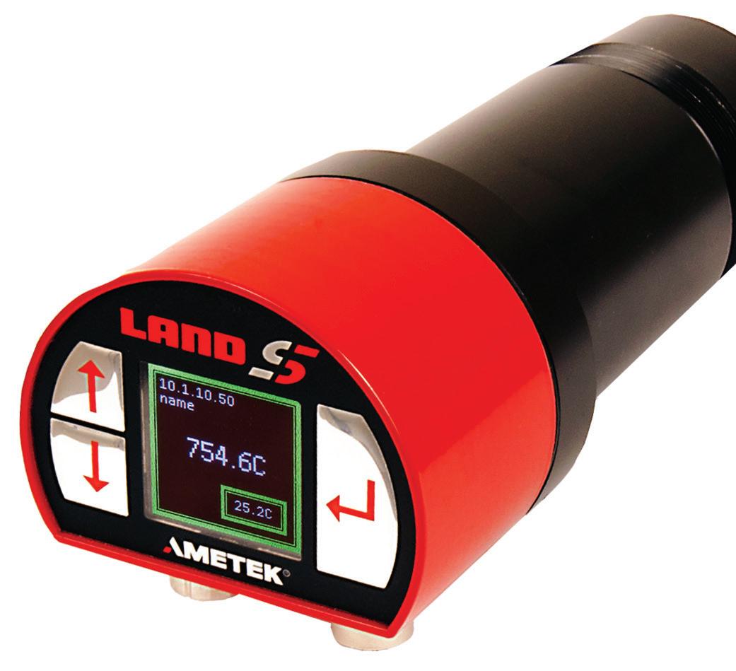
AMETEK Land SPOT+ AL
By Prasath Venkatasamy*
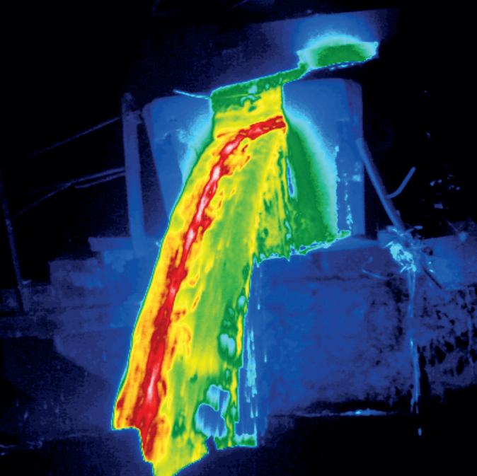
The accurate temperature measurement of liquid aluminium during melting and pouring is important to ensure high-quality casting and efficient process operation. Liquid aluminium temperature measurement during tapping ensures product quality and process efficiency while minimising waste or rework.
Furnaces are used in aluminium production to melt raw material and scrap at the primary stage, then for preheating ahead of processes such as rolling, extrusion, forming and forging.
Aluminium industry furnaces are designed to handle high temperatures, maintain precise temperature control, and ensure efficient energy usage. They are vital for the conversion of raw materials into molten aluminium, which can then be further processed into various forms, such as ingots, sheets, or extrusions, for use in different industries.
Temperature measurement of the metal is critical for the effective operation of aluminium furnaces. It provides essential information for the control and optimisation of the various processes involved in aluminium production, ensuring that energy use is minimised, and the processes are not overheated.
Additionally, it helps support safe and efficient furnace operation, along with quality assurance of the aluminium products.
Infrared thermometry is ideal for these types of measurement: it has a fast response, it is non-contact, and it works well on hot materials. A non-contact temperature measurement method is particularly useful, as it enables measurement of the material rather than the furnace wall.
Unfortunately, several of the characteristics of aluminium make it challenging for measurement instruments of all types to achieve accurate temperature readings. For example, its emissivity is low and varies with temperature, while each alloy has a different value.
That means it is not possible to correlate the intensity of infrared radiation emitted by the metal with its temperature, as is commonly done with steel, glass, and other industrial processes.

16
AMETEK Land SPOT+ AL
Furnaces International September 2023 www.furnaces-international.com LIFE OF A FURNACETECHNICAL FOCUS
* Global Industrial Manager Metals
Single-spot pyrometer measurements
Pyrometers are passive devices, detecting the infrared radiation emitted by the measurement object – they do not emit any radiation themselves. This makes spectral emissivity one of the most important parameters in non-contact temperature measurement.
Aluminium is difficult to measure because its surface has a low emissivity and therefore is extremely reflective – much like trying to make an optical measurement of a mirror.
When using mono pyrometers – that is, devices using a single wavelength – the spectral emissivity value for the object to be measured must be known, so that the pyrometer can determine the correct object temperature. Emissivity tables are available, but emissivity can vary with temperature, measurement wavelength, and surface conditions such as oxide film structure.
Ratio and Application pyrometers measure radiation at more than one wavelength to partially compensate for surface emissivity. Application pyrometers can also calculate and report the emissivity value as well.
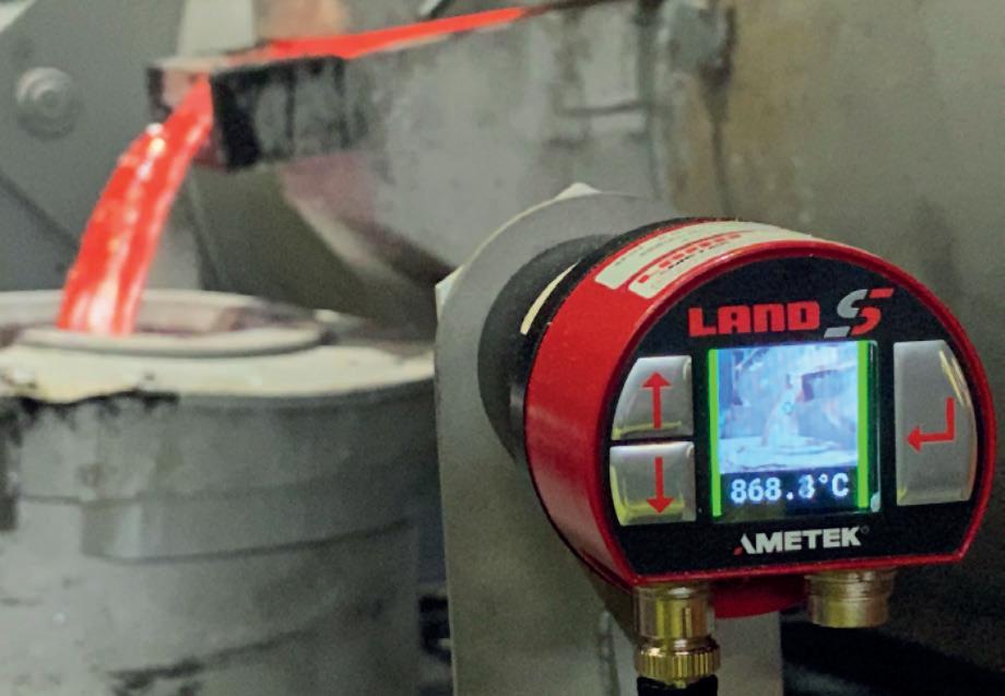
For example, AMETEK Land’s SPOT+ AL non-contact pyrometer uses measurements at carefully-selected wavelengths, combined with proprietary algorithms, to determine the temperature of hot aluminium.
Each SPOT+ AL has algorithms optimised for measurements of oxidised aluminium billets, freshly-extruded aluminium, and cooling aluminium at the quench exit.
The algorithms can also be adjusted to match the exact temperature characteristics of a specific alloy, using a one-time comparison with a thermocouple measurement.
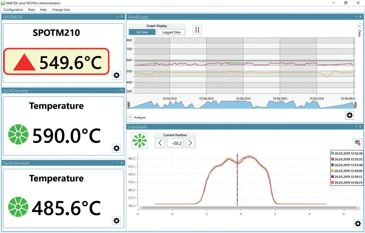
The SPOT+ AL also offers a Liquid Aluminium Mode, for accurate, real-time, high-speed measurements of tapping stream temperatures in applications such as melting and pouring.
Melting and pouring
The optimum pouring temperature for liquid aluminium depends on alloy type and casting geometry. The solid alloy must all be melted, but not overheated.
If the temperature is too hot, the chemical and physical properties of the aluminium and the casting may not meet
specifications and energy is wasted. If the temperature is too low, molten metal will not flow into all the cavities and apertures of the casting due to solidification.
Liquid aluminium temperature measurement during tapping ensures product quality and process efficiency, and minimises waste or rework.
The SPOT+ AL’s unique Liquid Aluminium Mode enables accurate live high-speed measurements of tapping stream temperatures, even on the most reflective liquid aluminium surfaces.
By choosing the preset liquid mode and aligning the patented green target spot with the pouring stream, the pyrometer gives continuous readings through the digital and analogue interfaces within 15 ms.
The integrated visual camera and SPOT+ AL patented green LED clearly indicate the target area to aid alignment. Combining the SPOT+ AL with the smart SPOT actuator, the spot detects and tracks the tapping automatically without the need for manual adjustment.
Furnace measurements
Delivering accurate temperature measurements inside smelting furnaces is particularly difficult because of reflections from hotter walls, fumes and particulates, dross buildup and surface materials.
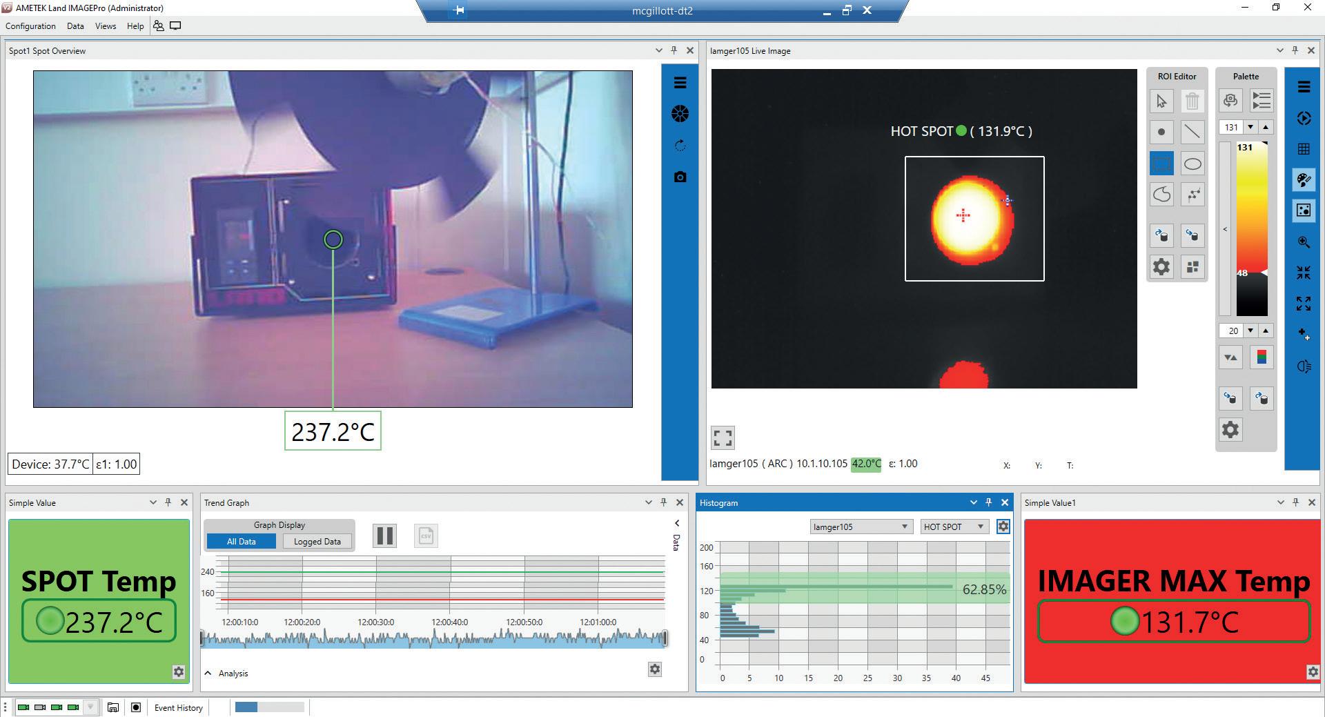
To overcome these issues, AMETEK Land has developed the MWIR-640 thermal imager.
Using a mid-range wavelength of 3.9 μm, the MWIR-640 is able to achieve a clear, continuous view through heavy smoke and hot furnace atmospheres – unlike visual camera systems – and provides an unparalleled view inside melt furnaces.
17 Furnaces International September 2023 www.furnaces-international.com
TECHNICAL FOCUS
Thermal Imaging & Processing Software
LIFE OF A FURNACE
This enables highly accurate and fully radiometric temperature measurement image data to be taken, stored, and trended over the lifetime of the furnace or boiler.
The MWIR-640 is supported by advanced IMAGEPro thermal imaging and data processing software, which allows long-term data trending and enables the early detection of leaks and temperature variations to help optimise processes.
Operators have a clear view of the critical areas within the furnace or boiler with more than 300,000 accurate point temperatures, measuring in the range of 300-1200 °C (572-2192 °F) and 500-1800 °C (932-3272 °F).
Providing advanced digital communications via IMAGEPro, the performance of the furnace or boiler can be monitored to easily identify hot and cold areas and any uneven heating can be viewed in real-time from the safety of the control room.
The high-resolution image, combined with the wide-angle field of view (90°), allows multiple areas to be imaged and measured simultaneously.
The MWIR-640 uses proven thermal imaging technology to accurately and continuously profile the temperatures within the furnace or boiler, providing improved data accuracy through automation and minimising risk to personnel by reducing the need for personnel to be in the hazardous area around the furnace or boiler.
Advanced process control
AMETEK Land’s MWIR-B-640 is used in Idletechs’ advanced process control system, which builds on the thermal imager’s capabilities to increase furnace efficiency.
Idletechs provides software for online analysis of large streams of data, extracting the essence using explainable AI and presenting it to operators in a way that enables them to make better decisions.
The result is better process control and improved maintenance – increasing profits and ensuring stable operations.
The Idletechs Furnace Monitoring solution makes it possible to optimise the aluminium smelting process by providing real-time infrared images of the furnace melt surface, accurate tracking of metal temperatures during each production phase, quantification and predictions of the melting of solids, monitoring of dross formation and removal, and the ability to analyse process changes.
The solution is designed for retrofit on existing furnaces and can integrate with existing data sources.
The MWIR-B-640 generates huge quantities of desperately-needed thermal behavioural data that were never previously available. Idletech’s system handles, distils, and intelligently interprets this key information to improve process efficiency.

By combining the high-performance thermal camera with real-time analytics, the system allows better process control, as operators can avoid running the process too long, saving time and fuel, and can plan operations better.
Process insight is also improved, with the ability to quantify and track key performance indicators such as formation of dross and slag, system temperatures, and melt times. This provides the basis for understanding how to improve operations and change recipes.
By tracking the melting process to avoid filling too early, and tracking maintenance operations to avoid manual errors, quality is enhanced. The system also delivers early warnings of changes in the furnace, and the detection of slow changes in the furnace, improving maintenance.
Conclusion


The advantages provided to aluminium furnaces by thermal imaging allow for more repeatable and reliable temperature measurements to be taken, as well as a greater understanding of furnace conditions during the process.
The ability to integrate these measurements into process controls can further improve product quality, including surface finish and desired metallurgical properties.
By measuring the variables involved, and understanding their effects on the process, aluminium operators benefit from a competitive advantage, attracting customers who demand high-quality aluminium products.
Moving forward, implementing thermal imagers into automated process control systems will enable a more efficient, optimised and automated factory for the future. �
18 Furnaces International September 2023 www.furnaces-international.com
AMETEK Land MWIR-640-Borescope
TECHNICAL FOCUS
LIFE OF A FURNACE
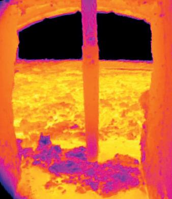
Getting to the true core of the matter!
Thru-process temperature monitoring of aluminium slabs and ingots in continuous pusher furnace heat treat processes prior to rolling operations.
By Dr Steve Offley*
Introduction: Aluminium Flat Rolled Product Market
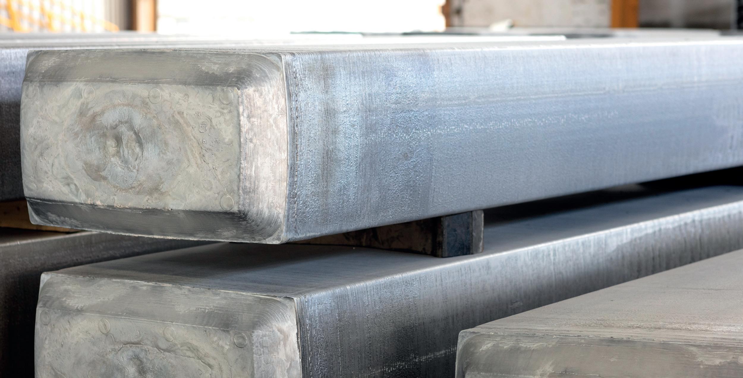
In today’s manufacturing market, aluminium, being lighter, safer and more sustainable, is increasingly becoming the material of choice. A key player in this market is aluminium flat rolled products. These include sheet, plate and foil. The market size is estimated to be worth USD 114240 million in 2023 with a CAGR of 4.8% during the forecast period 2023-2030.
Aluminium flat rolled products are usually manufactured by rolling thick aluminium (slabs, ingots or billets) between rolls that reduce the thickness. Aluminium rolling can be performed cold (cold working), where the rolling process hardens and strengthens the material through changing the micro-structure, but this may leave the final product brittle. Hot rolling in contrast requires heating of the stock material (hot working) between 260 and 550 °C (500 and 1022 °F) before being processed through roller mills of decreasing thickness applying force to the top and bottom of the slab. Hot rolling prevents most, or all work hardening and allows the aluminium to remain ductile. The classification of the final rolled product is determined by thickness plate (<0.25 inches / 6.3 mm), sheet (0.008 inches / 0.2 mm to 0.25 inches / 6.3 mm) or foil (< 0.008 inches 0.2 mm).
Aluminium Slab/Ingot Reheat Processing Control
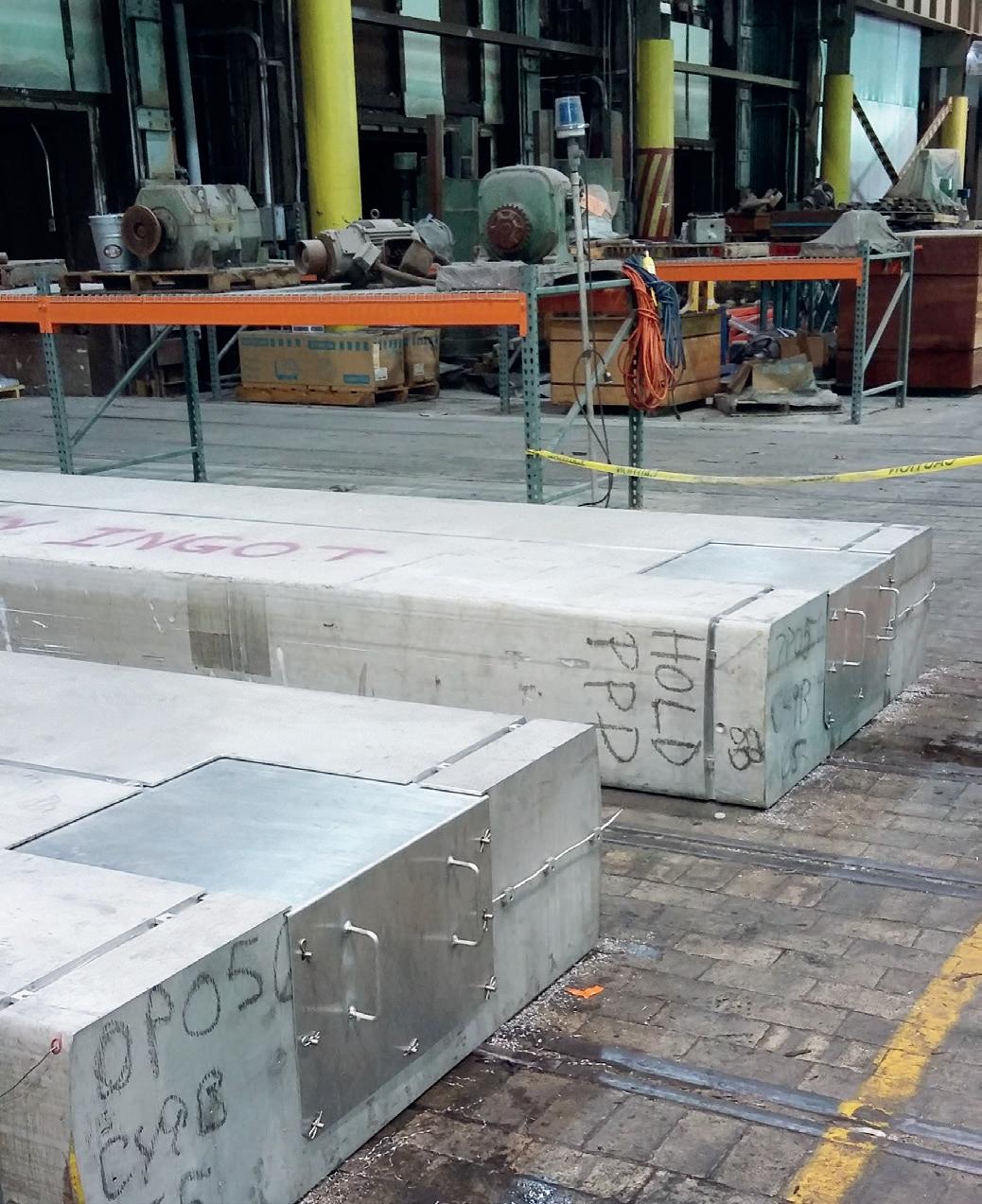
In the hot working of aluminium stock, the initial cast slab is passed through continuous pusher furnaces to reheat and homogenise at temperatures up to typically 550 °C (1022 °F). The actual set-point temperature and soak time employed in the process is obviously influenced by the stock characteristics including type of alloy and the physical dimensions of the slab, thickness, and overall thermal mass. Although modern furnaces incorporate sophisticated temperature control methods, often based on intelligent mathematical models, the success of the heat treat programs requires independent validation. The process engineer needs to understand how the furnace program characteristics, unique to each furnace (temperature and time) effect the temperature of the aluminium slab throughout the complete production heat treatment cycle (passage through the furnace) at different locations within the slab structure (length, width, and depth). Other techniques used for product temperature measurement in process, including furnace contact thermocouples and IR temperature measurement (spot, scanner, or camera) limit temperature to the slab surface and often are restricted to one face of the slab only. To achieve efficient hot rolling, it is critical the correct slab drop out temperature is achieved through the entire slab core.
Validation of Furnace Control Programs – Slab Temperature Profiling Challenge
Marketing Manager PhoenixTM Ltd UK
To validate the performance of the heat treat process, a temperature profile of the slab temperature at different locations within the slab through the heat treat furnace 19
Furnaces International September 2023 www.furnaces-international.com
*Product
LIFE OF
FURNACETECHNICAL FOCUS
A
is needed. Historically the temperature profile was achieved using the method of trailing thermocouples. An external data logger would collect temperature data from thermocouples attached to the slab fed through the furnace during the slab transfer. This measurement approach is not ideal for the following reasons;
� The number of temperature measurement points is limited due to cost and the difficulty of manoeuvring multiple long thermocouples through the furnace
� Due to thermocouples trailing into the furnace it is often not possible to charge slabs behind the test piece, meaning that the trial is carried out in a furnace that is not fully loaded. Temperature data is not therefore an accurate rep-
resentation of true production conditions.
� Opening and closing of furnace doors may inhibit the use of long thermocouples.
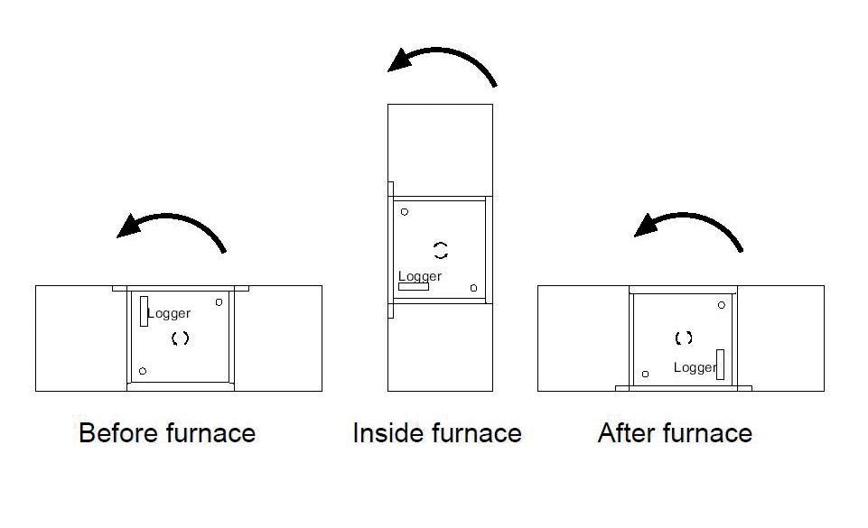
� In the pusher furnace the slab is rotated 90 ° at entry and exit from furnace which creates damage or disconnection risks to the fitted trailing thermocouples.
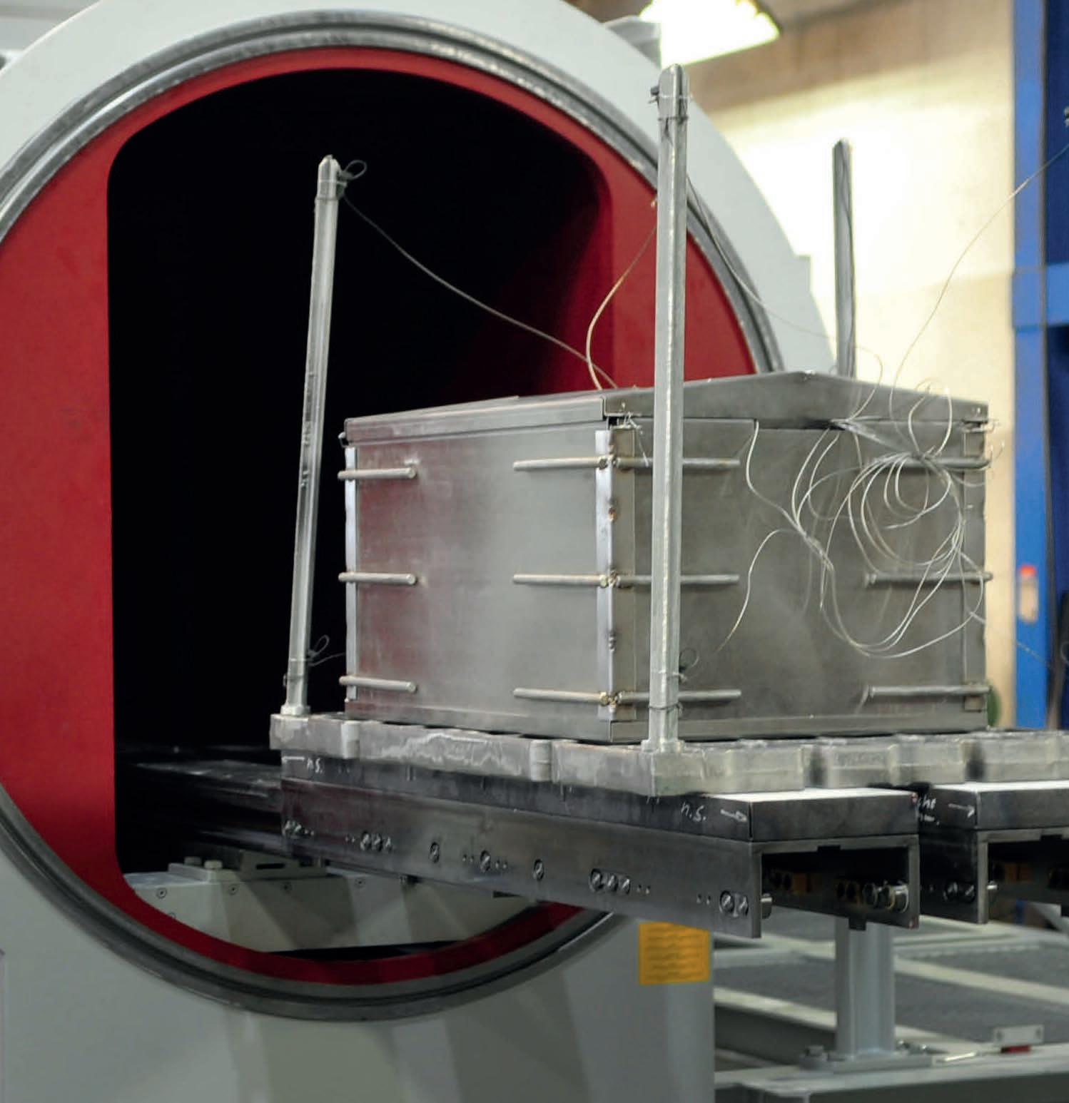
To eliminate the inherent problems of the trailing thermocouple approach, the alternative method of thru-process temperature profiling is recommended. As its name suggests the measurement system (data logger) passes through the process attached to the test slab during normal production conditions, measuring the temperature of the test slab using short

thermocouples at up to 20 critical points. The data logger is protected from the heat of the furnace by a highly efficient thermal barrier which keeps it at a safe operating temperature. As the monitoring system is self-contained within the test slab, the system is free to travel safely through the furnace without any of the inherent challenges of long trailing thermocouples as part of the standard production cycle within a fully loaded furnace.
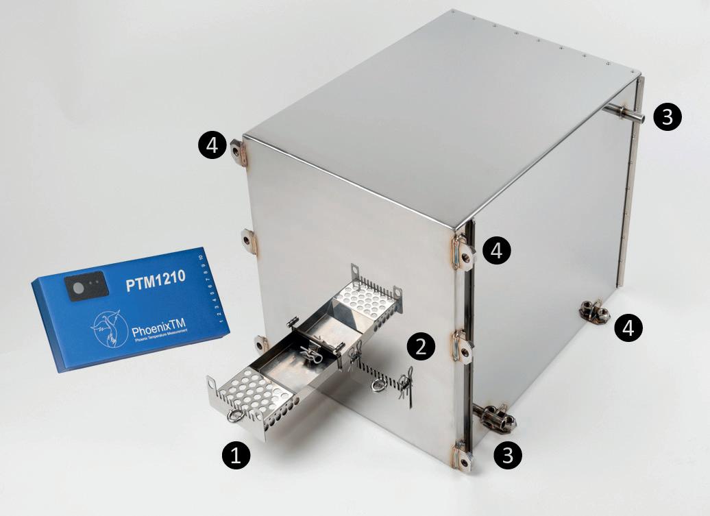
Thru-process Temperature profiling system design
PhoenixTM Data logger Range
At the heart of the monitoring system is the data logger designed specifically for
20 Furnaces International September 2023 www.furnaces-international.com
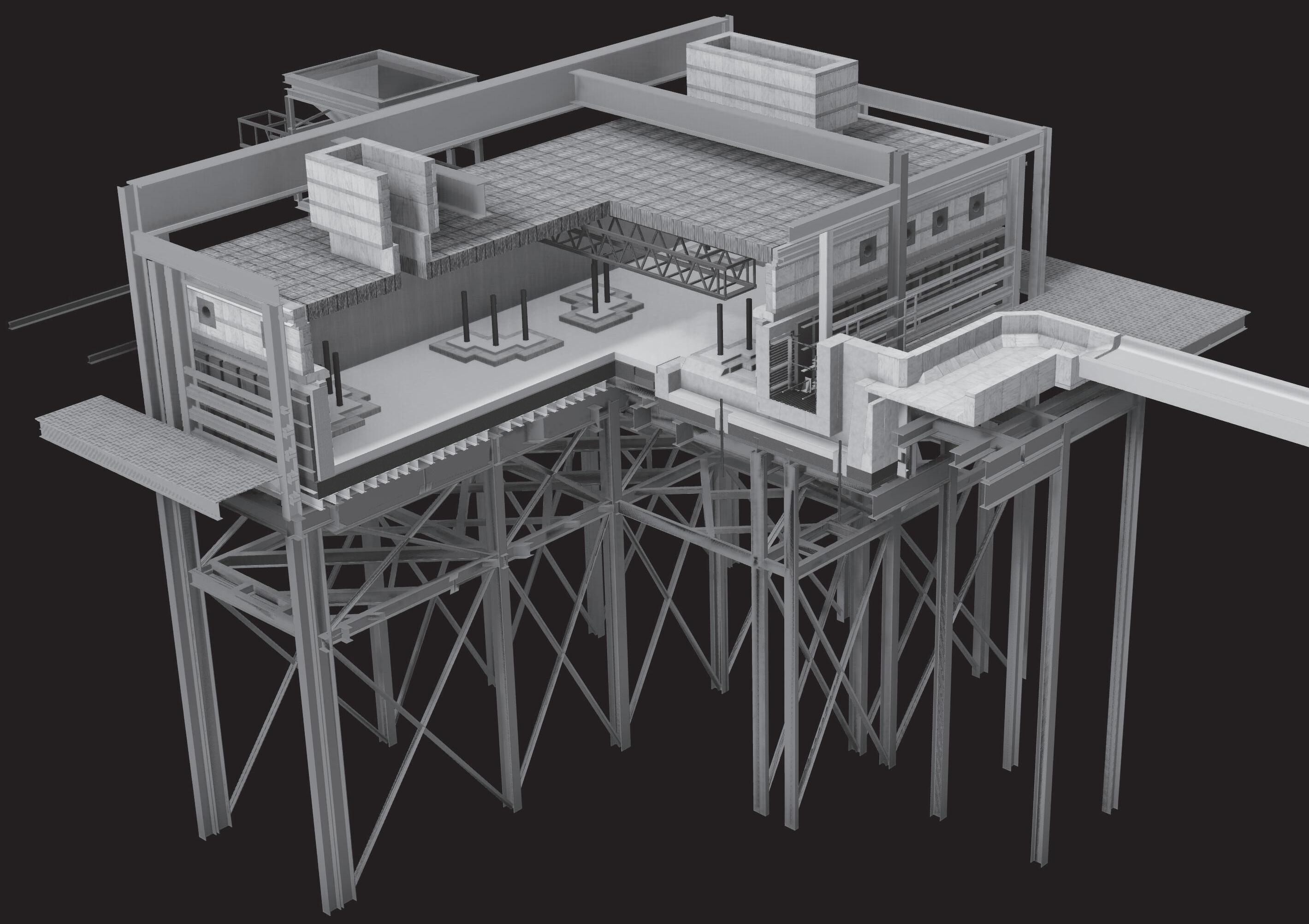
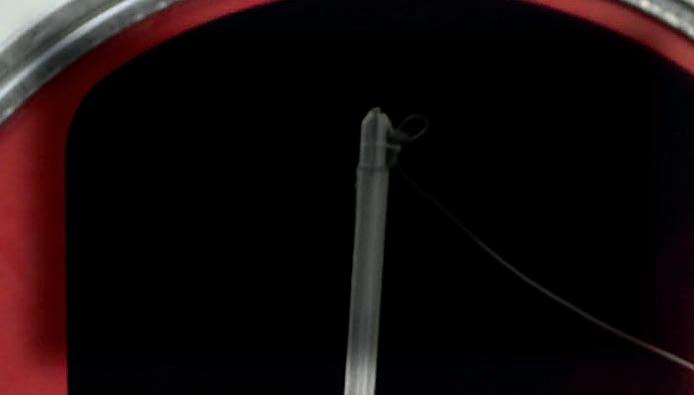
Figure 1. PhoenixTM PTM1220 20 Channel high temperature data logger shown in data logger barrier tray with IP67 thermocouple compression fittings ideal if water spray quenches are employed.
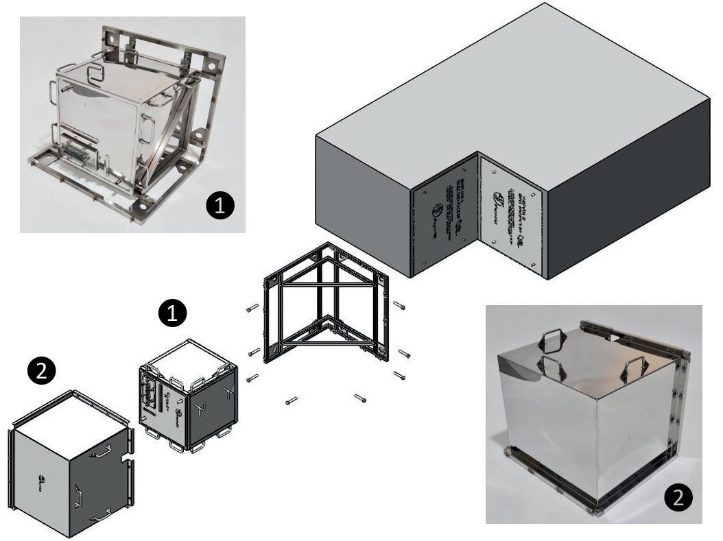
Figure 2. Aluminium slab thermal barrier showing (1 & 2) dual data logger tray within water tank and (3) filler and exhaust pipes and (4) slab mounting points.
Figure 3. PhoenixTM System embedded in aluminium slab/Ingot (1) - stainless steel cover to protect from high velocity air flow in furnace (2).
Figure 1
Figure 2
Figure 3.1 thru-process
TECHNICAL
Figure 3.2 thru-process
LIFE OF A FURNACE
FOCUS
use in the hostile heat treat environment. Data loggers can be provided in a variety of configurations to suit the specific demands of the process being monitored. Models ranging from 6 to 20 channels can be provided with a variety of thermocouple options (types K, N, R, S, B) to suit measurement temperature and accuracy demands (AMS2750 & CQI-9).
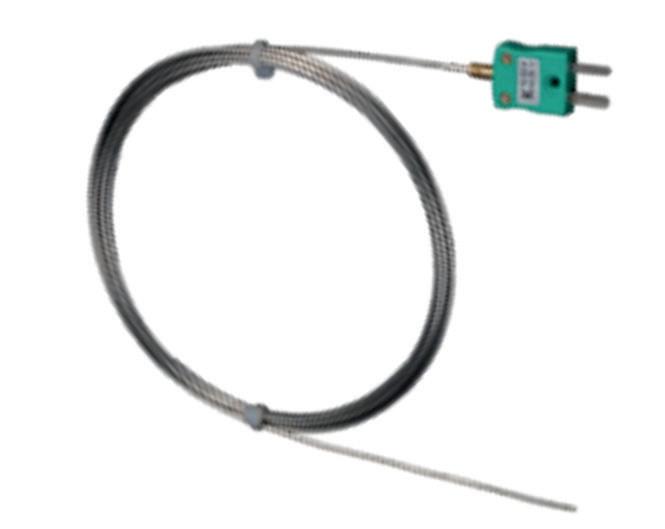
The loggers can be offered in either standard <80 °C (176 °F) or high temperature operating temperatures (Barrier Core Temperature <110 °C (230 °F) variants to allow use of either standard thermal barrier designs (Dual Phase - Heat Sink) or high performance (Phased Evaporation – Water Tank) as recommended for use in the demanding aluminium reheat pusher furnace monitoring application.
Although thermally protected by the thermal barrier, the operating temperature of the data logger during transfer through the furnace will increase up to the safe maximum operating conditions (100 °C (212 °F) in evaporative water barrier). The data logger temperature change, which would normally affect the thermocouple reading, is automatically compensated for using an accurate internal temperature compensation feature protecting the measurement accuracy in process.
Built to cope with hostile industrial environments the IP67 logger is capable of managing even the most demanding
processes where water spray quenching may be necessary.
Provided with Bluetooth wireless connection for short range localised download and reset (direct from within the barrier) the logger memory of 3.8M allows even the longest slab reheat processes (20 hours) to be measured with highest resolution to deliver the detail you need. An optional unique 2-way telemetry package offers live real time logger control and process monitoring with the benefits detailed in the later following section. (Figure 1&7)
Thermal Barrier Design
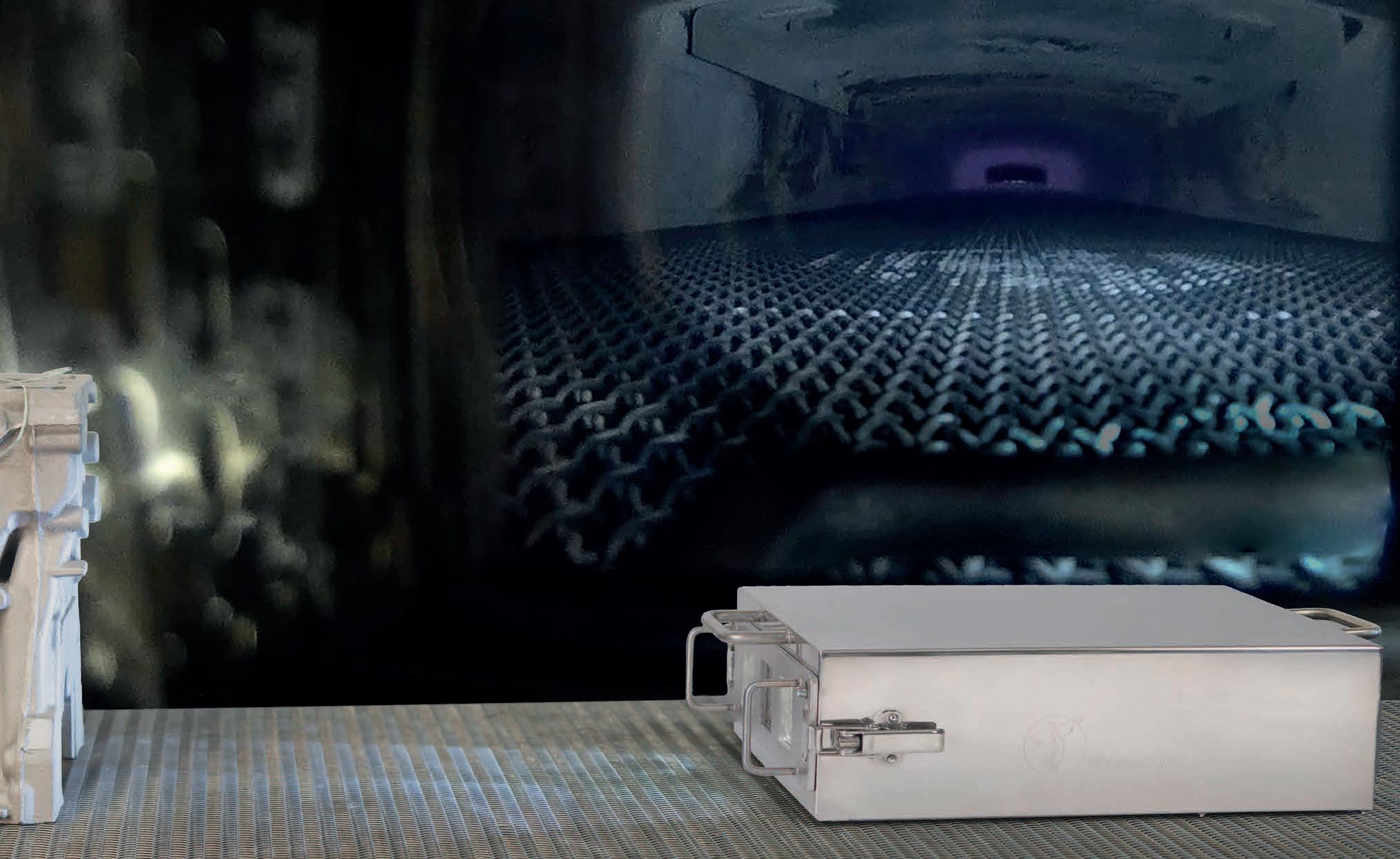
Heat treating a 30 tonne 600 mm / 24 inch thick aluminium slab requires significant heat to achieve homogeneity. Processes are typically therefore up to 20 hours at 500 °C / 932 °F and as such the thermal barrier used to protect the data logger needs to be very efficient but at the same time be compact enough to allow safe installation within the slab. For such process the recommended thermal barrier design is based on a dual phased evaporation technology. The high temperature data logger operating safely
21 Furnaces International September 2023 www.furnaces-international.com
Figure 4. PhoenixTM System schematic showing exploded thermal barrier configuration with slab mounting frame (1) Thermal barrier photo positioned on frame (2) Thermal barrier with fitted protective high velocity air cover.
Figure 4
Figure 5
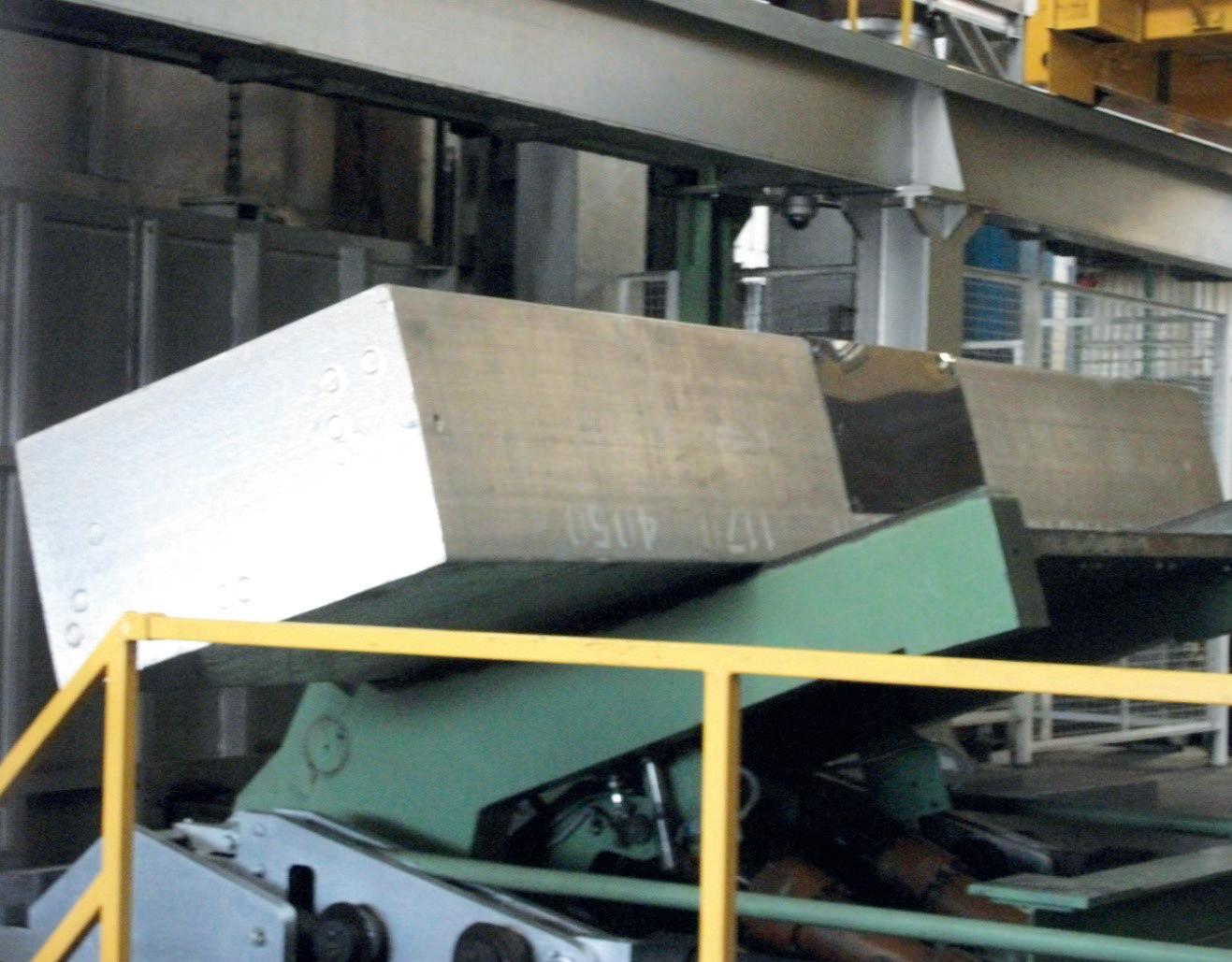
Figure 5. Test Slab with installed monitoring system being loaded into the furnace (1) and schematic showing rotation steps (2).
TECHNICAL FOCUS
Figure 6. Test Slab with thermocouple channels routing MI thermocouple cable to point of measurement at the desired depth (channel 1-8).
LIFE OF A FURNACE
at temperatures up to 110 °C / 230 °F is housed within the dry cavity of a water tank. Data logger sealing options within the thermal barrier are available including IP67 compression fittings, recommended if water spray quench steps are employed in process (Figure 1). During transfer through the furnace, the water heats up to its boiling point at 100 °C / 212 °F and then maintains the temperature as water phase changes from liquid to gas (steam). The rate by which the water temperature in the tank rises is further controlled by an outer skin of microporous insulation, which helps reduce rapid temperature changes and associated risk of distortion problems for the thermal barrier structure.
The exact thermal barrier protection is governed by the capacity of the water tank. When specifying the correct thermal barrier design often there is a fine balance between maximising the size of the water tank and volume of water available to the outer dimensions of the thermal barrier suiting the size of the slab being monitored.
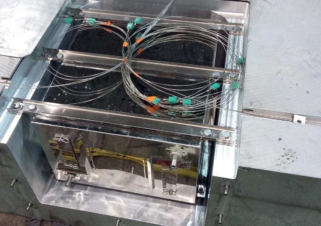
A feature of the pusher furnace design is that the slab is rotated at the entrance and exit of the furnace to maximise loading capacity. The rotation of the slab (Figure 5) and therefore also thermal barrier could create problems with water loss and deterioration in thermal capacity. The water tank construction is designed therefore in a unique way to orientate water filler and steam exhaust pipes to minimise water loss during any rotation
Fitting the monitoring system to the test slab
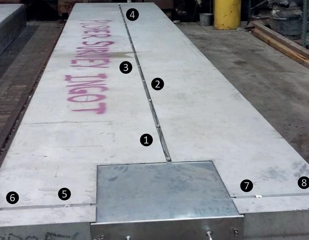
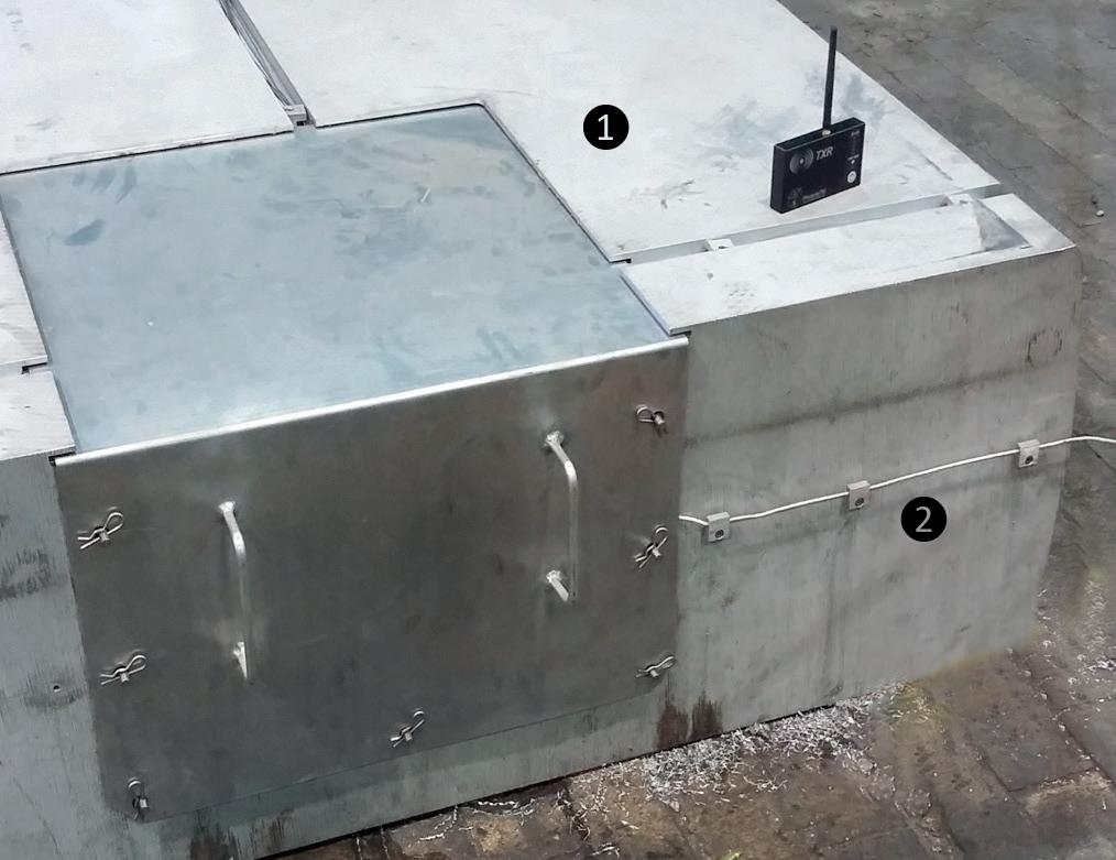
Generally, a test slab is prepared by machining a portion out to accept the monitoring system with the thermal barrier often positioned centrally and in a position where it will not impede any equipment used to load / unload the slab (Figure 3). Bolts securing the thermal barrier to the slab should be of a sufficient depth and diameter to ensure they don’t break away from the hot aluminium as the slab rotates at the furnace exit.
The assembled monitoring system fitted within the slab cavity is covered with an external metal shield (Figure 3). The shield has two purposes to firstly protect the thermal barrier from high levels of heat transfer from high velocity hot air convection and maintain air flow patterns over the slab itself to maintain normal production heating conditions.
Thermocouple Placement
Temperatures within the slab are measured from the tip of the mineral insulated thermocouple as shown in figure 6. To position the tip at the exact location / depth within the slab pilot holes need to be drilled in the slab. Depending on the type and diameter of thermocouple to be used, aluminium bushes may need to be used as guides. If a small diameter thermocouple is used, for example a 1.5mm 1/16 inch diameter mineral insulated type, then it would be impractical to drill a small hole say 300mm / 11.8 inches deep to the measuring point. In this case a large diameter hole can be drilled, and bushes used. It is essential that the thermocouples are firmly secured to the
slab as they travel from the data logger to the measuring point. Often the thermocouples are channelled along groves in the slab surface so that the cables are confined within the slab eliminating snagging risks in the furnace, or on charging / discharging the equipment.
Real Time Communication
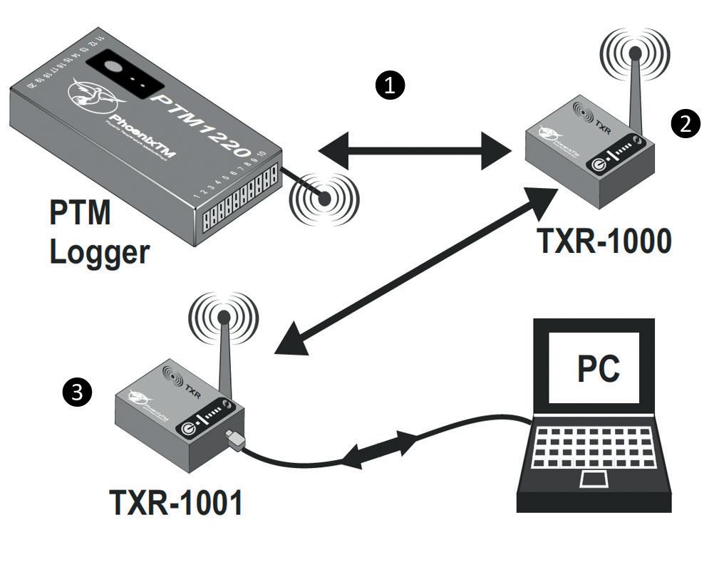
Conventionally profile data collected during the test is downloaded to a PC running analysis software post run. Alternatively, it is possible to collect data in real time live utilising an RF telemetry option. The data logger is available with a unique 2-way RF system option allowing live monitoring of temperatures as the system travels with the product through the furnace. Furthermore, if necessary using the RF system it is possible to communicate with the logger, installed in the barrier, to reset/download at any point pre, during and post-run.

Provided with a high performance ‘Lwmesh’ networking protocol, the RF signal can be transmitted through a series of routers linked back to the main coordinator connected to the monitoring PC (Figure 7). The routers being wirelessly connected are located at convenient points in the process to capture all live data without any inconvenience of routing communication cables as needed on other commercial RF systems. The operator from the convenience and comfort of his control room / office can see what is happening in the process live. For a 20 hour slab reheat process, such live data gives the operator confidence that process is working in real time, without that nervous wait with a non-RF system to download from the logger at the end of the run.
22 Furnaces International September 2023 www.furnaces-international.com
Figure 7. Installed system on slab showing (1) RF telemetry Antenna and (2) portable RF repeater unit transferring live temperature data direct from furnace back to (3) RF coordinator linked to the monitoring PC.
step. (Figure 2)
TECHNICAL FOCUS
LIFE OF A FURNACE
In many processes, there will be locations where it is physically impossible to get a RF signal out of the furnace. With conventional systems this results in process data gaps. For the PhoenixTM system this is prevented using a unique fully automatic ‘catch up’ feature. Any data that is missed will be sent when the RF signal is re-established ensuring in most applications 100% in-process data review.
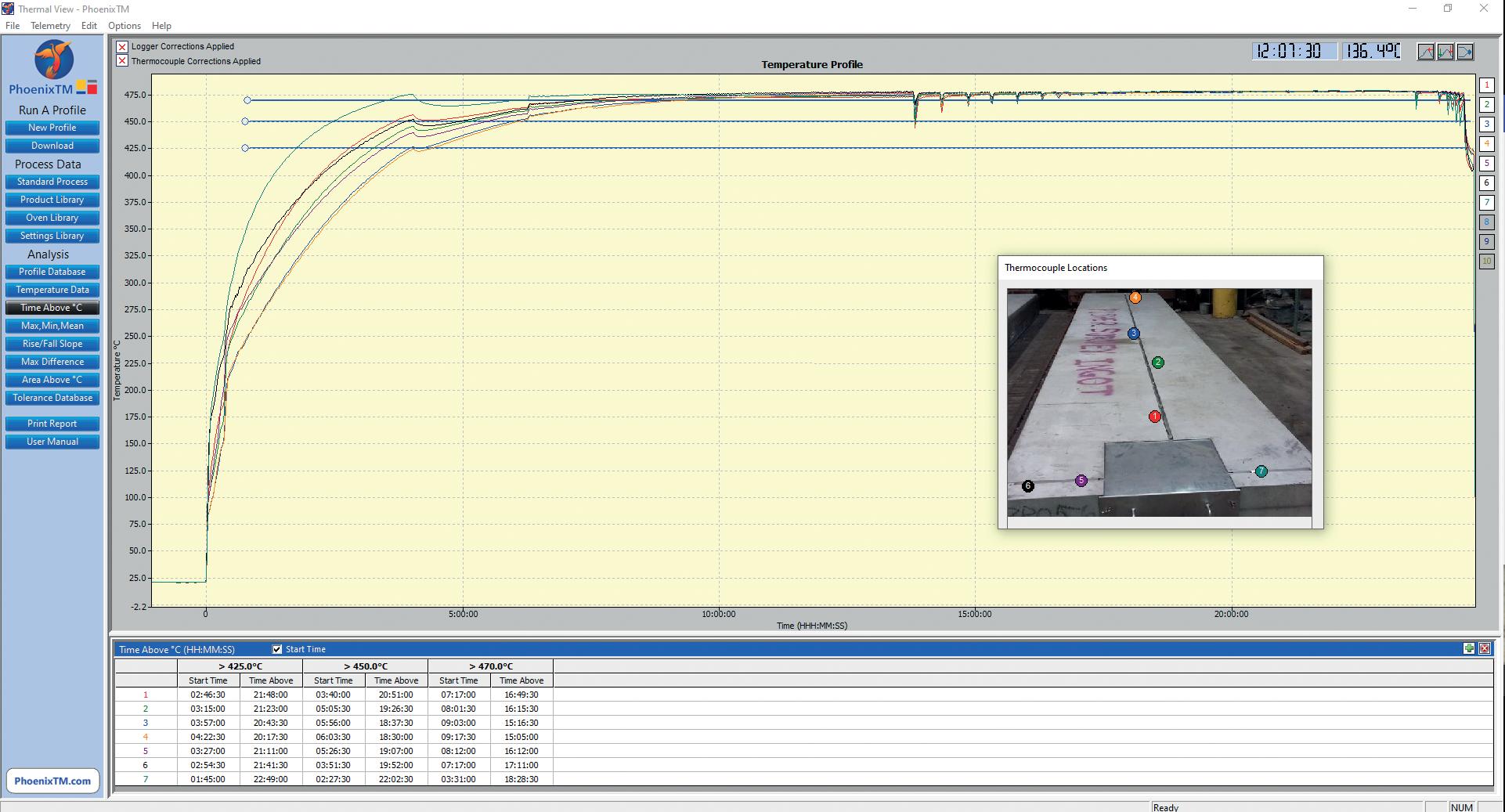
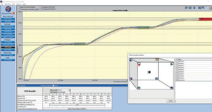
Handling the Data
The result of the thru-process monitoring step is the invaluable temperature profile graph (Figure 8). The profile graph represents a thermal fingerprint of what temperatures the aluminium slab achieved through the process at the selected locations over the slab foot print and at specified depths within its core. The profile data can be interrogated in detail to fully understand the heat treat operation at the critical product level and be used to control, optimise and validate the furnace operation. Such data is essential to accurately set-up and verify mathematical model predictions used to control the furnace operation and ensure that the process is run efficiently to save energy, improve productivity and reduce
carbon emissions.
Conclusion
Thru-process product temperature profiling is an accurate and efficient method to measure aluminium slab internal core temperatures in pusher furnaces prior to hot rolling operations. Product temperature information gleaned helps to ensure that the correct thermal balance
is achieved efficiently throughout the product thickness. Non-homogeneous temperature conditions can be prevented that would potentially cause variation in downstream processing and compromised final product quality, ultimately leading to energy wastage, higher costs, and rejections. �
www.phoenixtm.com
We are your premium refractory partner

As a supplier of high-quality customized refractory solutions we can assure you of:
• A comprehensive range of refractory materials for applications up to 1800 °C for all types of industries

• Expert know-how of customer processes, engineering and installations
• Long-term partnership in technology and services
• Solutions to reduce your carbon footprint and to save energy
www.rath-group.com Think higher! Accept only the best refractory solutions and expertise
Figure 8. Temperature profile graph showing the temperature variations within the aluminium slab core over the entire heat treat process. Soak times at critical temperatures can be accurately calculated to ensure that drop out temperatures and rolling operations are performed correctly.
LIFE OF
FURNACETECHNICAL FOCUS
A
*Principal Consultant, Glass Container Manufacturing Consulting Ltd. (GCMC), peter.firth@gcmc-worldwide.com, www.gcmc-worldwide.com
Assessing Boilerwatch® for potential benefits in glass manufacturing
Meet the Scientific Environmental Instruments Inc. (SEI Inc.) GUYS.
These GUYS have been providing flame combustion monitoring and control to various industries using acoustic technology and a reliance upon the ideal gas law.
The system trade name BOILERWATCH comes from the original application in coal power plants which have very high internal combustion thermal sheers and tremendous fuel usage with multiple burners. Since then, the BOILERWATCH system has been installed in many other industries that burn fossil fuels, like oil refineries, petrochemicals, and combined cycle power plants. Siemens even have a patent for using the BOILERWATCH system at the exit plane of a gas turbine. See Patent No. US8565999B2 dated October 22, 2013.
Search any online patents database using that patent number, or use the short code link given here to access the patent document www.bit.ly/US8565999B2 . An illustration extracted from the patent document is shown in Figure 1, of which the illustration on the right will mean more to you by the end of this article.
Now the SEI Inc. GUYS are turning their attention to the benefits it can bring to the glass industry. They are actively looking for glass industry partners to prove the envisaged benefits in glass manufacturing. Recently I have been assisting SEI Inc. in raising awareness of their system through my “Meet the GUYS” initiative on LinkedIn.
NOTE: GUYS stands for Glass Up-and-coming Young Suppliers. The background to the reason for my support for the GUYS is covered in my article published in the November/December 2022 edition of Glass International. Refer to that article if you are interested to know more about this. A short link to that article is given here: www.bit.ly/MTGGI
LIFE OF A FURNACETECHNICAL FOCUS 24
Furnaces International September 2023 www.furnaces-international.com
A technology used in other industries for combustion monitoring flame temperatures is now proposed for glass furnaces. By Peter J Firth, MSc*
I would normally write from the point of view of Glass Container Manufacturing, which is my background and experience. However, in this “Meet the GUYS” article, I have to think more widely since it applies to the furnace area of the process. As we know, the furnace is similar and common to several glass manufacturing processes including glass containers, flat glass, and glass tableware, amongst others.
It will also apply to a wide range of glass furnace types and should be of benefit for any furnace type where there is a flame firing across the surface of the glass. This is where it extends its generality to other industries that are non-glass industries. In fact, it is already applied to optimise other industrial processes requiring burner set-up optimisation since the 1980s.
As already indicated, the main application has been in boiler flame optimisation where it has been marketed and implemented under the name of BOILERWATCH® MMP-II-SSX-LD. This is exactly the same technology as SEI Inc. is proposing will be of benefit to glass furnace flame and gas temperature monitoring. The acoustic pyrometer is
an advanced industrial instrument which provides a fully digitised measurement of high combustion-gas temperatures.
In the original boiler flame and gas temperature monitoring application, combustion gas temperature data permits fuel trimming control within the heaters and boilers. The system is non-intrusive and operates on the principle that the speed of sound in a gas is proportional to the temperature of that gas (according to the ideal gas law).
Acoustic transceivers are mounted on the outside of the walls of the heater/ boiler, and a high-intensity acoustic signal is launched through the gas stream. Since the distance between the sound source and receiver is known and fixed, the average temperature of the gas along the acoustic path is computed from an accurate measurement of the sound signal’s transit time. This is illustrated in Figure 2, where the similarity to monitoring a furnace firing will be instantly recognisable.
In this application, it has been shown that excess O2 can be reduced by at least 0.5%, which results in a vastly significant increase in fuel efficiency and heat rate. The cost savings from this benefit alone can pay for the BOILERWATCH®
MMP-II-SSX-LD system quickly enough to cost-justify its installation. With this Acoustic Pyrometer system, the gas temperature in any kind of furnace or boiler can be measured to give a distribution map temperature, all in real time.
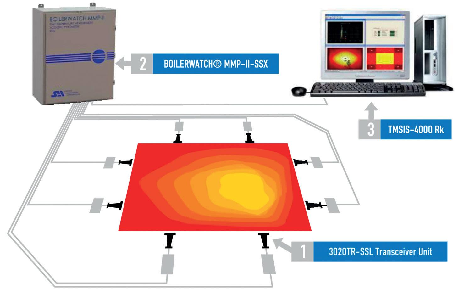
In an early application of this technology, the results of the acoustic system were compared to the temperatures of thermocouples that were the pre-existing temperature measurement system in the gas stream. The comparison of temperature readings was used to prove the application of the technology was sufficient as a replacement for the matrix of thermocouple measurement points.
To apply this technology glass-furnace gas-firing combustion, a set of broadband-noise transceivers are mounted around the furnace and pointing into the combustion chamber. The noise emitted by each transceiver is generated from service air.
The transceivers mount on the exterior furnace in the typical position of a conventional observation door (see Figure 3). The maintenance of the transceivers is expected to be negligible because the same service air that is used to generate the sound, also serves for cleaning and cooling the devices. Electrically speaking, each transceiver simply consists of a microphone and solenoid valve.
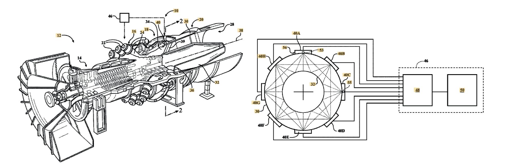
The number of transceivers and the exact configuration will depend on the specific furnace upon which the technology is being applied. SEI Inc. can give installation drawings specific to each furnace and specify exact requirements according to their experience in other similar process applications.
When installed, each transceiver takes its turn in emitting broadband noise while the other transceivers listen. The noise patterns and timing of the reception are then compared to the emitted noise. This then continues stepwise through each
25 Furnaces International September 2023 www.furnaces-international.com
Figure 1. Patent Illustration taken from the Siemens Patent US8565999B2 Using BOILERWATCH Technology for Control the Exit Plane Temperatures of a G as Turbine
LIFE
FURNACETECHNICAL FOCUS
Figure 2. Overview of the BOILERWATCH® MMP-II-SSX-LD System, now proposed for Glass Furnace Firing Flame Temperature Monitoring.
OF A
transceiver taking its turn to emit noise while the others listen.
Calculations based on the ideal gas law are then made to create a two-dimensional map of temperatures in the gases across which the sound paths have passed. The calculation takes into account the known physical distance between each of the transceivers. See Figure 4
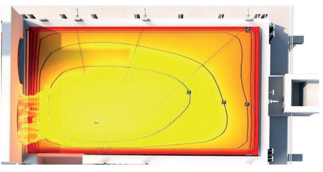
A short-link to videos of both an endfired furnace and a side-fired furnace is given later in this article. In addition, there is a brochure embedded in the link for further explanation of the technical points which have already been discussed.
Now turning attention to the potential benefits, these will be the same as any current benefits known to be obtained from a focus on the furnace surface firing. The difference is there will be a digital map of the temperature upon which to base burner adjustments. In the future, maybe this information can even be used to create the basis of feedback for an automatic flame and combustion control loop. However, this is currently uncharted territory in the glass industry, but one that SEI Inc. are keen to explore with the partners they are now seeking from the glass industry.
To mention a few potential benefits, we can easily envisage optimisation of combustion to give fuel efficiency as well as better control of the furnace hot spot, particularly on end-fired furnaces. For emissions control, by reducing temperature imbalances in the combustion plane, NOx production can be reduced at source. Problems arising from flame impingement can be prevented by identification of this occurring and setting up alarms. Achieving a more uniform
temperature distribution will also reduce thermal stress and increases the service life of critical furnace parts including the exposed sidewalls, bridgewall and crown.
An interesting aspect raised by a quite number of people I have been in discussion with is the fact that the acoustic pyrometer should be able to easily monitor hydrogen flames. This will solve the problem of such flames being much less visible to the human eye than when using fossil fuels. In this sense, it solves a potential problem with the future use of hydrogen firing, which is being touted as the solution to significantly lowering the carbon intensity of the glass industry.
SEI Inc. are currently offering the first FIVE systems sold into the glass industry at an Introductory Price of $148,000 (USD). This is also to include performance guarantees, details of which are to be agreed upon with the client.
In addition to monitoring the combustion chamber, the application of the same technology is also proposed to have applications in monitoring furnace regenerators. This has been a recent topic of focus and discussion with several high-profile glass refractory suppliers and glass manufacturers recently. Monitoring the cross-sectional temperature distribution at the top and bottom of the regenerators would give essential efficiently performance information. It has also been proposed to use this to optimise the performance of the regenerator.
However, I am sure many other potential applications to aid the glass-making process will quickly become evident. Not least of which will be the integration of the acoustic pyrometer information into the overall process control and optimisation systems. To that end, recent discus
sions with Glass Service from the Czech
Republic show they are interested in integrating Acoustic Pyrometer information within their Expert System ES IIITM system, with the objective of even further enhancing their ES IIITM system performance results.
Therefore, the first several Acoustic Pyrometer applications in glass would possibly also generate such additional optimisation interest and support from Glass Service, A.s. (Inc)., where they also have their Expert System ES IIITM system(s) already installed.
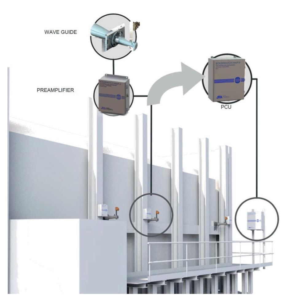
Similarly, the integration of the acoustic pyrometer information together with camera-based temperature measuring systems is also being discussed with relevant technology suppliers. These are all seen as complimentary technologies as the acoustic pyrometer simply brings additional information that is not easily available in any other temperature measuring systems.
If you or your company are interested to be one of the first to apply this technology in glass, the contact details for SEI Inc. are given at the end of the video and also at the end of their brochure. Additionally, there is a website with contact information available at:
www.acoustic-pyrometer.com
Here is the short link to the explanatory videos (end-fired and cross-fired furnaces applications) as well as the SEI glass application proposal brochure: www.bit.ly/SEIAPGI
NOTE: If you are viewing the above link from your smartphone, use the menu button (the one with several horizontal lines) to access the different items of content available.
Finally, to keep up-to-date with all the latest GUYS information, use the short link www.bit.ly/FOLLOWMTG to access the LinkedIn “Meet the GUYS” Page. Then click to “Follow” that page and additionally click the Bell to the right of the Banner and select the Top radio button to get notified of All New Posts. �
26
Furnaces International September 2023 www.furnaces-international.com
-
Figure 4. TwoDimensional Flame Heat Map Generated from Acoustic Signals Passing Above the Flames.TECHNICAL FOCUS
Figure 3. Transceiver Mounting on the Side of the Furnace at Furnace Flame Level.
LIFE OF A FURNACE
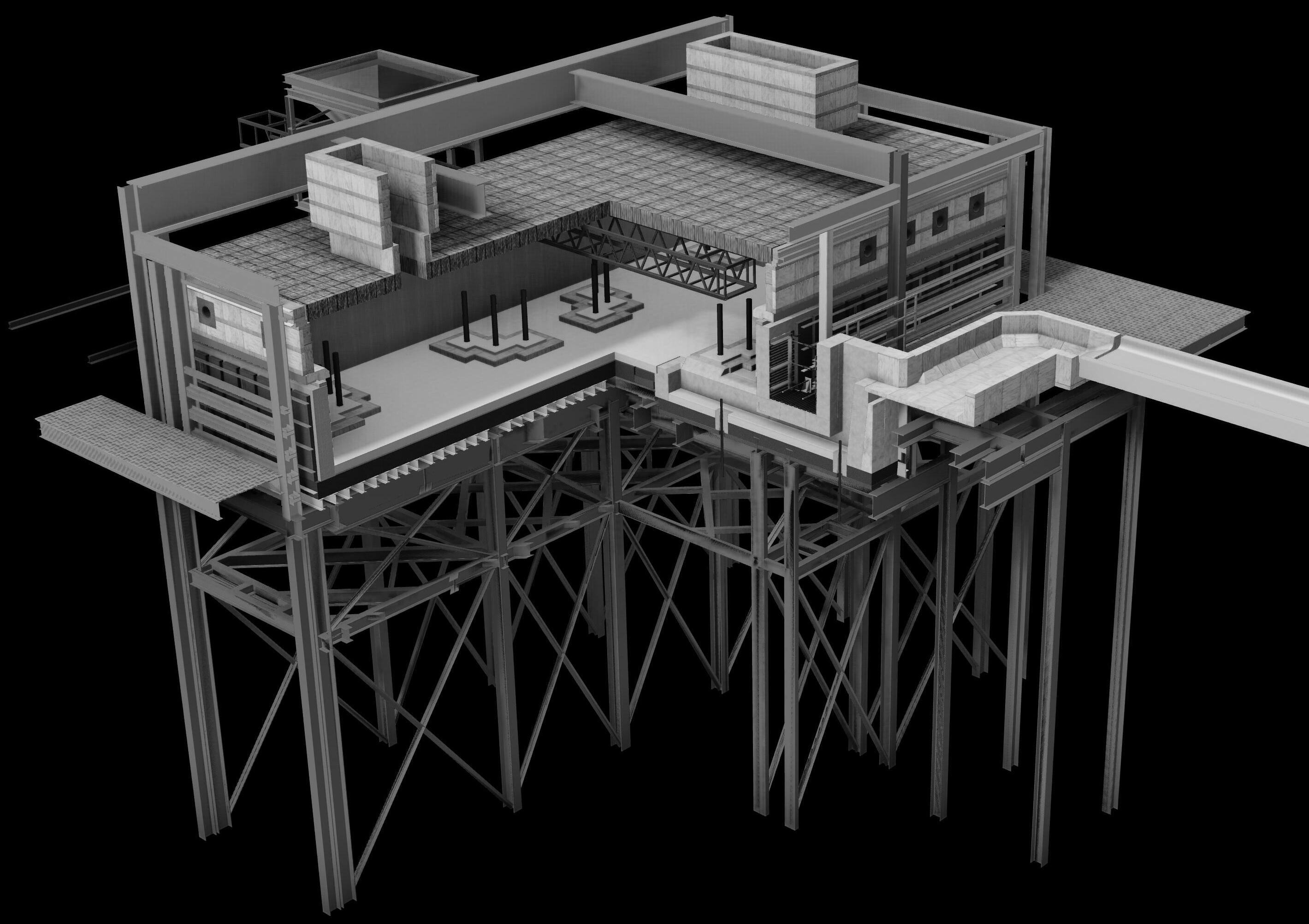
INNOVATION AS STANDARD ® TOLEDO ENGINEERING / TECOGLAS / ZEDTEC / KTG ENGINEERING / KTG SYSTEMS / EAE TECH www.teco.com
Second steps of energy and CO2 reduction – use of Isotherms
By Neil Simpson*
With over 30 years of experience in combustion, Neil Simpson is an Independent Consultant based in Scottish Borders with over 20 published patent applications. Initial work was in Steel Reheat, Thermal Oxidisers and Process Industries including designing burners for LCV wood gas. The last 25 years have focussed on the glass industry, including oxy-fuel. Whilst a primary focus has been supporting glass manufacturers since 2016, Neil has been a Consultant to AMETEK Land. Lucky guy in the right place at the right time who realised that In furnace thermal imaging can be used to optimise furnaces. Training is now a major portion of activities which post Covid 19 are no longer online but “hands-on”. For the last two years Neil has offered a Decarbonisation course.
This is the second article in a series that will look at energy and CO2 reduction in furnaces using commercially available technology. Whilst several technologies apply to glass melting furnaces, each will have applications in other industry segments, including Aluminium Reverb, Steel reheat, Cement kilns, Biomass and SMR.

In furnace thermal imaging
CCTV has been used in furnaces for over 30 years to support furnace operations. In-furnace, thermal imaging is a technology which has been commercially available for over ten years. Today with 2K, HD cameras, millions of continuously measured temperatures produce a high-definition visual image of the furnace. Sadly, in the majority of applications, operators consider the visual image only and not the relevance of the thermal data.
The 1st article looked at the ability to have virtual thermocouples on glass furnace and cement kilns. One of the biggest challenges is being able to analyse the massive amount of thermal data that a thermal camera can generate! The case study that is being used in this article is on a steel reheat furnace. The images are with one of the original 656 Near Infra Red Borescope developed by Peter Droegmoeler of AMETEK Land. The images were taken over 10 years ago and whilst the furnace location is unknown these have been published previously. Whilst the 2K High Definition camera today has 2.9 million continuous temperature measurements 10 years ago the 656
28
Furnaces International September 2023 www.furnaces-international.com
LIFE OF A FURNACETECHNICAL FOCUS
*Independent Consultant based in Scottish Borders
had a mere 324,000. Picture 1.
In virtually every application the priority is making good product, a close second is protecting the furnace asset then energy and emissions. If you don’t make good product then the specific energy and emissions are exponential. Looking at the basics of thermodynamics the hotter the furnace process, the higher the heat transfer by radiation. In most combustion applications the flame heats the refractories and then the refractory radiates the heat to the product/process.
LIFE OF A FURNACE
The temperature of the product and the furnace are equally important/inter-related. Picture 2.
In analysing the images from the steel reheat furnace I was reminded of one of my first commissioning in 1990. I was a young graduate and worked for Laidlaw Drew (Combustion Engineers –Scotland). Whilst best known for glass melting we also supported steel reheat furnaces. At that time we had developed a mathematical model which was meant to control the speed of the through-put
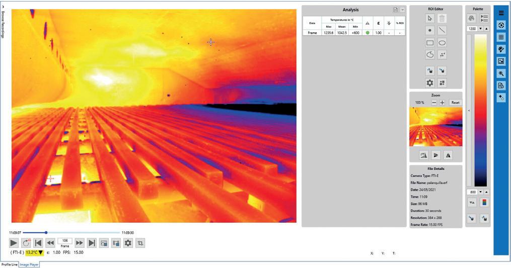
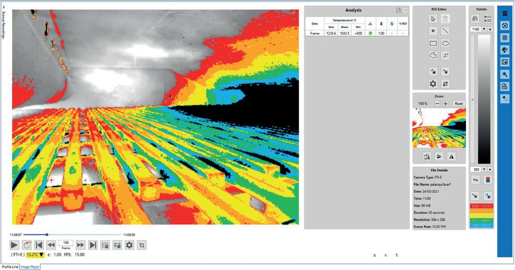
of the furnace not the speed of the mill! I remember starting one shift where the billets on a pusher furnace were so hot that they had bonded together! Axes, wedges and sledge hammers were being used to try to separate the two billets where were stuck in the discharge door which was sized for one! Once cleared they ran the mill as fast as they could till the billets were so cold and hard that they broke the breakdown roller. It was crazy. Whilst we demonstrated on many occasions that they could roll more steel per day by running at the speed of the furnace the “human factor” always won when we were off-site. Energy savings were significant. I recently learned that overheating the steel can often result in the billets/blooms being able to be recycled so a double loss!
In the case study the data from only one frame will be analysed. Typical frame rate we use is 5 frames per second. A future article will show how integrating turbulent diffusion flames can identify which burner is making the most NOx!
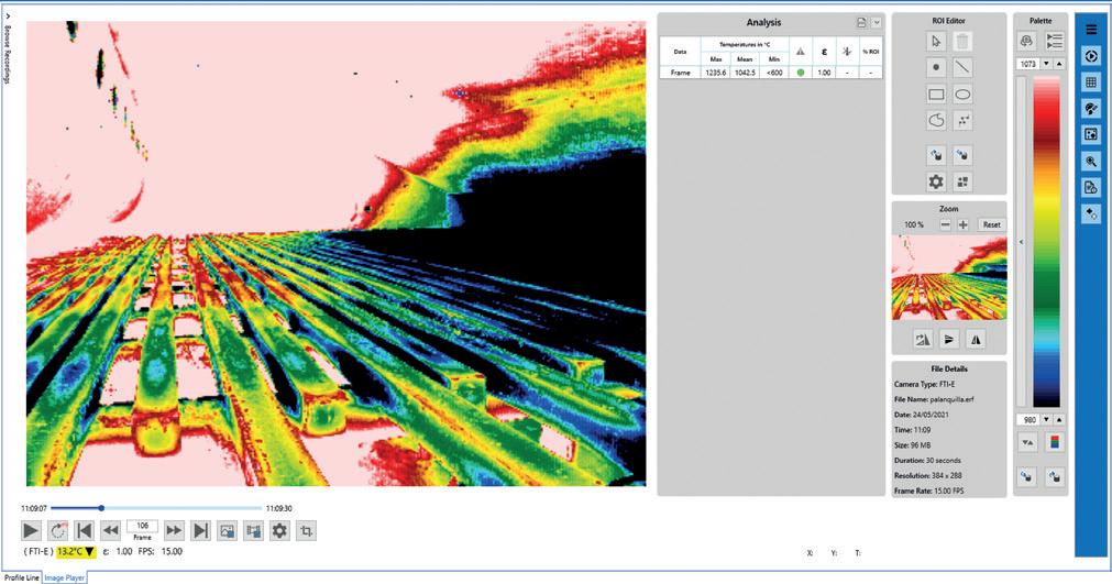
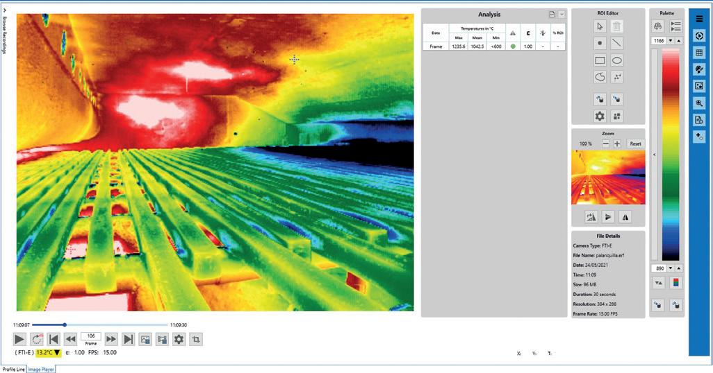
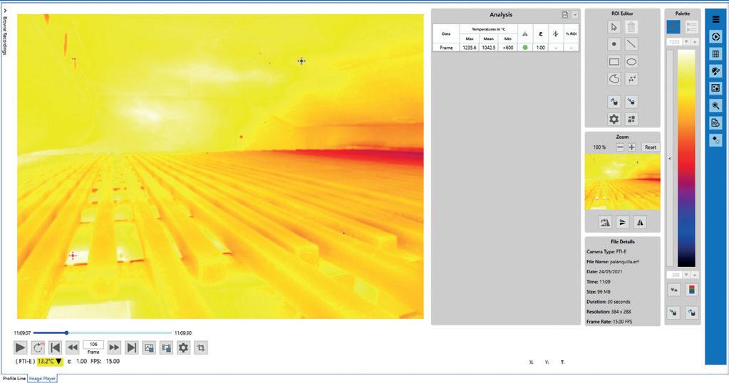
Use of Isotherms
When I am suggesting using Isotherms
29 Furnaces International September 2023 www.furnaces-international.com
Picture 1. Initial view of a steel reheat furnace survey. Using auto temp. range.
Picture 3. New 62 colour isotherms palette. With 186° temp range each colour corresponds to 3°.
Picture 4. 93° temp band 62*1.5° isotherms initially looking to billets only. Also shows upper burner blocks are colder on near side. May be an impact of angle/ reflection, but may be worth checking the combus
-
tion air distribution.
Picture 5. 25° isotherms covers billet temperatures close to the camera. Shows clear inbalance ‘variance’ in billet surface temperature. The last 14 analysis slides have all been from one frame. The recording speed is 36 frames per second! the image is 324,000 optical pyrometer readings.
Picture 2. Reduce temperature range manually to increase contrast/ resolution. Can see two flames top fire. Can start to see the impact of the walking beam skids. Hottest flame in lower zone.
TECHNICAL FOCUS
I am suggesting region with the same temperature or temperature bands. In the image below I am using a 62 colour Isotherm. The minimum temperature is 980C and the upper is 1166C so a temperature band of 186. Each colour is equivalent to 3degrees. Picture 3.
This band was used since it highlights the three flames which are the hottest in the upper preheat. The red cross + indicates that the highest temperature is actually in the lower preheating zone. Clearly this is a walking beam furnace but what amazed me the most was to see the impact of the water-cooled skids on the temperature of the steel. On reflection this is obvious but the point of the billets in contact with the skid is the coldest. Picture 4
Focusing on the billets closest to the camera the temperature range is 93degrees where each colour corresponds to 1.5degrees. It is clear that the billets are colder closer to the camera and hotter on the far side. It is unclear if this in-balance is by accident or by design. IF the rolling
mill direction is on the far side of the furnace, then it can be desirable to have the leading edge of the billet hotter in order to reduce the impact and potential damage of the leading edge on first pass of the breakdown roller. Picture 5.
The final image is one which uses 5*25 degree isotherms from 950 to 1075. The isotherms show the thermal profile of the roof relative to the surface of the billets and is around 100 degrees hotter. The roof profile is determined by the combustion from the burners in the upper heating zone. Considering the heat release near the camera and the curved profile on the billets suggests that the lower zone is side fired and so parallel to the billets.
Whilst the initial camera location is in the preheating zone there were also measurements taken in the tonnage and soaking zones.
Test bloom & survey

The thermal cameras can be installed and operational continuously which is the most common operation. There is also the opportunity to use in a survey mode. One of the optimum opportunities to have a survey is when there is a test bloom planned. The camera can move to the peep hole closest to the test bloom as it progresses through the furnace. In all situations the top surface will be visible but in the case of walking beam there will be an opportunity to capture the downstream leading edge and then the upstream trailing edge as it moves past the camera location. Ignoring the impact of the water cooled skids the temperature at the centre of the billet will be a function of the surface temperature and residence time. The data from the camera can be used to validate cfd and traditional mathematical models. If the bloom centre is at the desired temperature then there is the opportunity to reduce the temperature and/ or speed up the throughput of the furnace. Clearly surface over temperature can be measured and alarms implemented to minimise rejection of product. �
CONNECTING THE FURNACES INDUSTRY


Digital Magazine
Furnaces International is an English language journal dedicated to the production of rnaces. Circulated each quarter in March, June, September and December.
Directory
The Furnaces International Buyers’ Guide is the essential guide to rnace manufacturers and suppliers of rnace equipment and services to the industrial heating/process industry. Providing comprehensive company listings, product information and key contact details, the guide is published in December each year.
Website


Packed with information on the rnaces industry and continually updated with news for professionals, rnaces-international.com also features special articles and interviews with leading industry gures.
Newsletter
A round-up of the top news stories is sent to more than 44,000 industry professionals every month. You can register online to receive the weekly newsletter and keep up-to-date with the latest news from across the rnaces manufacturing industry. Sign up at rnaces-international.com
Other Publications
Aluminium International Today (AIT) is the leading bi-monthly English language journal dedicated to all sectors and regions of the international aluminium manufacturing and processing industry. Subscribe to the free weekly newsletter at aluminiumtoday.com

Glass International o ers readers the latest news from across the hollow, container, flat, and speciality glassmaking industry and is the o cial media partner for Glassman events. Subscribe to the free weekly newsletter at glass-international.com
Steel Times International is the key publication for the steel market, reporting on iron and steel making issues from all corners of the globe. Subscribe to the free weekly newsletter at steeltimesint.com
PUBLISHED BY
30 Furnaces International September 2023 www.furnaces-international.com
FIND OUT MORE AT FURNACES-INTERNATIONAL.COM
Furnaces-June23-PortfolioAd-HalfPage-185x128mm.indd 1 11/07/2023 15:30 LIFE
FURNACETECHNICAL FOCUS
OF A
New SMS reheating furnace at DanSteel for processing of thick continuously casted slabs
Goli-Oglu E.(PhD), Mesinov S., Filatov A. DanSteel, Frederiksvaerk, Denmark
Della Putta P., Fabro J. SMS group SpA, Tarcento (UD), Italy
This study is describing the technical, technological and metallurgical features of reheating process of continuously casted large-scale slabs with cross-section of up to 400×2800 mm made of low-carbon microalloyed steel in a reheating furnace of the latest generation at the DanSteel rolling complex 4200. The technical characteristics of the reheating furnace, installed in 2022, ensure high quality heating process of slabs used for production high-quality heavy plates weighing up to 63 tonnes, which are particularly in demand in the offshore wind energy and bridge construction industries. Installed new furnace is providing increased uniformity of heating along the thickness, width and length of 250-400 mm slabs with average maximum temperature gradients in the three directions not exceeding 30°С and reduced consumption of natural gas to the level of 31-32 m3/t of the finished product.
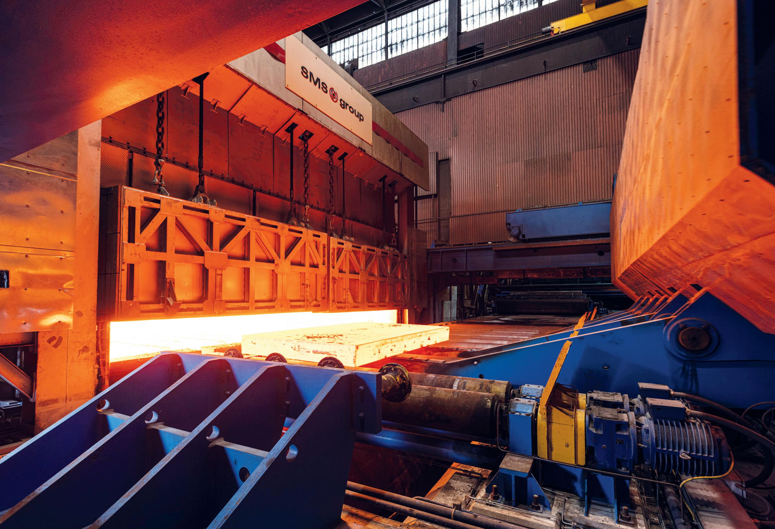
Figure 1. Effect of reheating temperature on particle size (a) and austenitic grain size (b) in steels
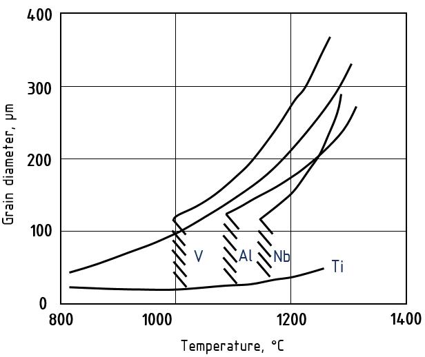
[5] microalloyed simultaneously with Ti and Nb:
1 - steel with low titanium additions (Ti/N=3.24);
2 - steel with 0.02% Nb and Ti (Ti/N=3.33)
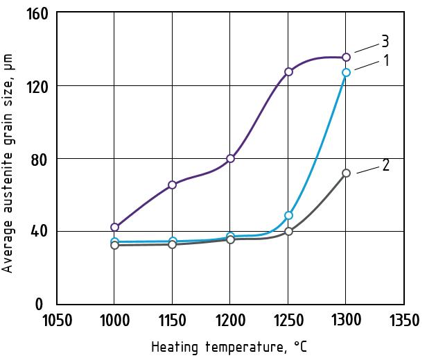
3 - steel with increased titanium content Ti/N=4.55
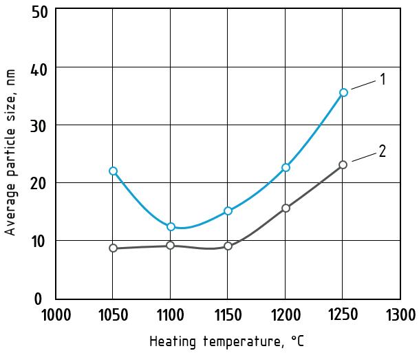
31 Furnaces International September 2023 www.furnaces-international.com
a b
Figure 2. Growth pattern of austenitic grains in steels containing various microalloying elements
LIFE OF A FURNACETECHNICAL FOCUS
The production of structural heavy plate steel is a complex multi-step process, the technological steps and operations of which have an impact on product quality and production economics. Slab reheating for rolling is one of the key process steps in the technological chain, directly linked to the quality and cost efficiency of heavy plate production process.
At DanSteel’s rolling complex 4200 [1], continuously casted (CC) slabs are heated either in pusher type furnace or walking beam furnaces depending on their cross-section. In the case of big-size and heavy-tonnage slabs with a cross-section of H×B up to 400×2800 mm, heating takes place in the latest generation of the SMS group walking-beam reheating furnace, installed in 2022. The main objectives of the installation of the new reheating furnace were the expansion of the product range towards the production of XXL high-quality heavy plates weighing up to 63 tonnes, which are most in demand in the offshore wind power and bridge construction industries, as well as improving the quality, economic and environmental parameters of slab reheating process.
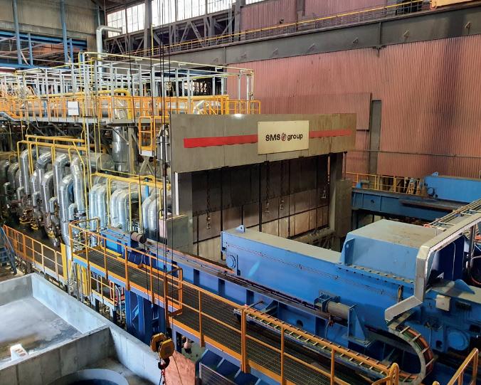
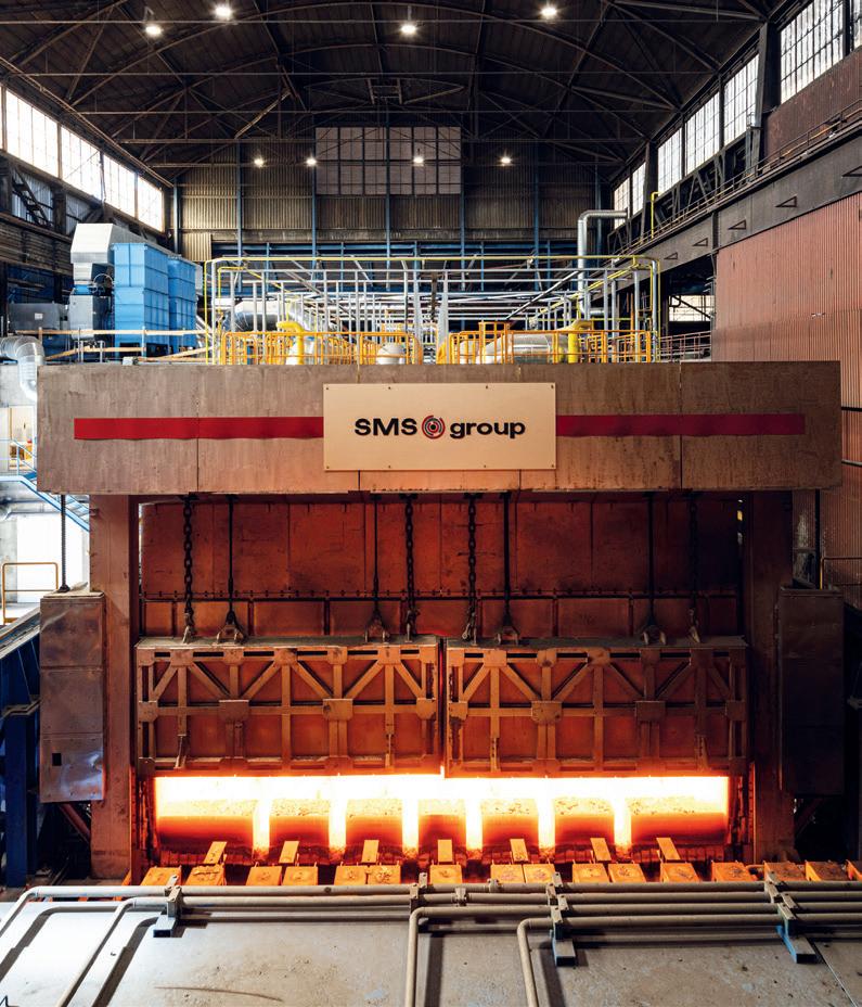
The aim of this article is to describe the technical, technological and metallurgical characteristics of heating of large-sized continuous cast slabs made of low-carbon microalloyed steels and their realisation using a new heating furnace of the latest generation at the DanSteel rolling complex 4200.
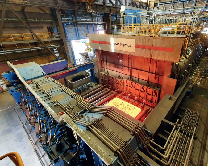
Metallurgical characteristics of slab heating
Heating of low-carbon microalloyed steel slabs is one of the key technological steps in forming the optimal microstructural condition of heavy plates and their surface quality. In conjunction with
microalloying, the technological parameters of heating affect such important characteristics as the average grain size and uniformity of the austenitic structure, the composition of the solid solution and the type/thickness of the surface scale. In terms of heavy plate quality, the main realised task at the reheating stage is to obtain at the exit of the reheating furnace a slab with a setup temperature, the minimum temperature gradient along the thickness, width and length of the slab, optimal quality and quantitative condition of the surface scale.
The heating temperature and its uniformity are important to form a microstructure of increased uniformity. It is known [2] that a fine-grained austenitic steel structure has an increased grain boundary surface per volume unit, which leads to an excess of free energy of the system, which creates a driving force that determines the subsequent grain growth. The austenitic grain grows exponentially when heated in certain temperature ranges and this grain growth tendency is always present in low carbon microalloyed steels. There are two general mechanisms of austenitic grain growth when heating slabs: normal and abnormal growth, that is, when reaching a certain temperature, which depends on the chemical composition, the austenite grain begins to increase very rapidly in apparent diameter. Abnormal grain growth can be observed in austenitizing steels containing strong CN-forming elements. Anomalous grain growth is not observed in simple low alloyed Si-Mn steels but at heating temperatures of 1150-1200°C the grain grows to very large sizes (200 μm and larger) [3]. To avoid exponential grain growth of austenite during heating for rolling, dispersed particles that inhibit grain boundary migration are effectively used [4]. The undissolved particles inhibit the migration
of grain boundaries and thus inhibit the growth of austenitic grains. The nature of the release of particles and their effect on the average size of the austenitic grains of Ti and Nb alloyed low carbon steels is shown at Figure 1. It is important that the slab at the exit of the furnace has a given heating temperature without gradient limit deviations.
The main microalloying elements that form the optimal (fine grain) austenite structure as a result of the solid-solution effect and the formation of nitrides and carbides during slab heating are titanium, niobium and vanadium (Figure 2) [5]. Titanium forms nitrides, which are stable at high temperatures in the austenitic range and allow control of the austenite grain size during heating before hot deformation. The binding of free nitrogen, which has a high affinity for carbide forming elements, by titanium has a positive effect on steel ductility and makes niobium more effective. Niobium is an effective microalloying element for refining the austenite grain during heating for rolling [6]. It also has the positive effect of inhibiting austenite recrystallization during thermomechanical rolling [7].
It is worth noting a number of works [8,9,10], in which it was shown that increasing the heating temperature of V-Ti-Nb steel and the associated austenite grain enlargement does not significantly affect the size of the recrystallized grain, formed in the temperature range of complete recrystallization after repeated deformation under the same temperature and deformation conditions. This experimental result at first sight contradicts most recrystallization models [11, 12], according to which the size of recrystallized austenite grain depends on the initial (before deformation) grain size and deformation temperature. Figure 2
The microstructure and mechani-
32 Furnaces International September 2023 www.furnaces-international.com
LIFE OF
Figure 3. DanSteel walking beam reheating furnace no. 3: a) General view of the furnace; b) Slab discharging area FURNACETECHNICAL FOCUS
a b
A
cal properties of the finished product directly depend on the heating temperature and are determined by the size and homogeneity of the austenitic grains, the stability of the austenite itself, influencing the condition of the excess phase and, consequently, the kinetics of its subsequent transformation. For timely recrystallization processes and control of dispersion hardening, it is necessary to balance the uniform fine-grained austenitic microstructure and the transition of dissolved particles into solid solution when defining the heating temperature. Also, the heating temperature must be sufficiently high to fully undergo recrystallization in the interdeformation pauses [13]. It should also be considered the possible negative phenomena of local and general overheating that occur when heating a slab above a certain, for a given steel, temperature and lead to a sharp increase in the austenitic grain size. The decreased heating temperature allows for a number of technological advantages: the possibility of reducing the pause time for cooling before the finishing step of rolling, increasing productivity of furnaces due to reduced heating time for rolling, and therefore the mill as a whole, as well as reducing the cost of the product due to saving fuel and reducing losses on scale. However, it should be remembered that some groups of low carbon steels have an optimal temperature range for
by moving the walking beam in four steps: lifting, moving forward, lowering below the level of the fixed beams and moving the walking beams backwards. The speed of slab moving in the furnace is controlled by changing the movement intervals between the movement cycles of the beams and depends on the variety of heated slabs. Slab discharging from the furnace is carried out shock-free, using a special machine that moves the slabs from the furnace beams to the mill roller conveyor. The furnace is equipped with a modern automated process control system and a system of instrumentation and sensors that allows the heating of steel without the direct involvement of technical personnel and provides for the measurement, regulation, control and recording of all operating parameters.
The furnace type is reheating, walking-beam, regenerative, multi-zone, double-row, double-sided heating, frontal charging and discharging furnace. The furnace is designed for natural gas operation with the possibility of a quick
heating, target temperatures above or below which increase the heterogeneity of the microstructure. Thus, ensuring uniform heating to a given holding temperature and discharging slabs from the reheating furnace for subsequent rolling is an important technological task and contributes to the formation of austenitic microstructure and solid solution state of low carbon microalloyed steel with increased uniformity.
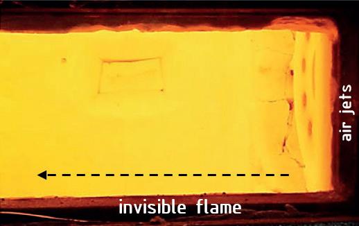
DanSteel walking beam reheating furnace
In 2022, DanSteel and SMS commissioned a new walking-beam reheating furnace (Figure 3) with a design capacity of up to 100 tonnes/hour, expanding the range of slabs heated to a maximum cross section of H×B 400×2800 mm and improving heating quality. The maximum temperature difference between the coldest and the hottest points on the slabs is not more than 30°C. The new furnace has been designed by SMS with a focus on environmental and energy efficiency and has reduced CO2 emissions by 17-18% compared to the furnaces already in operation in the plant.
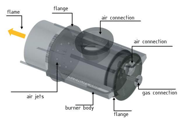
The walking beam reheating furnace is designed for heating cast carbon, low-carbon and low-alloy steel slabs weighing up to 63 tonnes. The main production characteristics of the furnace as part of DanSteel 4200 rolling complex are shown in Table 1
Slabs are moved through the furnace
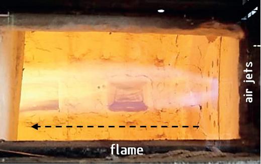
33 Furnaces International September 2023 www.furnaces-international.com
a b c
Figure 4. SMS-ZeroFlameTM burners used in DanSteel’s walking beam furnace: a - burner structure; b - flame operation; c - flameless operation
Features Size Value Productivity t/h 100 Maximum furnace temperature °C 1360 Maximum temperature gradient C ≤30 Dimensions of slabs to be heated: - thickness 200 - 400 - width mm 1250 - 2800 - length 2300 - 7700 Weight of heated slabs t up to 63 Slab temperature at the exit of the furnace °C 1000 - 1250 Metal losses with scale % ≤ 0,65
Table 1. Main production features of DanSteel walking beam furnace no. 3
Characteristics Size Value Dimensions: - usable length mm 28 650 - width 0 8800 Maximum consumption of natural gas m3/h 5 200 Specific consumption of natural gas m3/t ≤ 31,4 Nitrogen oxide concentration NOX mg/m3 ≤100
Table 2. The main technical characteristics of furnace no. 3 at DanSteel
LIFE
TECHNICAL FOCUS
OF A FURNACE
conversion, within three weeks, of up to 40% of the capacity for hydrogen operation. The conversion is carried out by means of a minor modernisation of the burner’s inner circuit, the installation of hydrogen storage auxiliary equipment and the regulation of the hydrogen supply to the modified nozzles. It is planned, that the replacement of natural gas by hydrogen will also reduce the consumption of natural gas by ~ 40% and hence reduce the negative impact of the process on the environment. Feeding control as well as optimum pressure is controlled by a special automated control system. Table 2 shows the main technical characteristics of the furnace.
The air is heated in a metal recuperator, located on the furnace roof. The combustion products pass between the tube and the air passes through the recuperator tubes. The air is blown by a blower into the recuperator and transported to the burners through thermally insulated air ducts. The gas and air from the common pipelines are supplied to each zone via zone headers, on which flow meters and actuators for flow controllers are installed to ensure an ideal furnace atmosphere with an O2 content of about 0.7-1.0 %.
The furnace has 6 heating zones, 3 upper and 3 lower, with 24 SMS-ZeroFlameTM burners [14] (figure 4a) for ultra-low nitrogen oxide concentrations and high thermal efficiency. The burners consist of a metal casing with external cladding for heat protection, several fuel and combustion air lines, a pre-combustion chamber and an air deflector made of refractory material with high alumina content.
The particular design of the installed burners allows them to operate using three modes:
� Flame mode (Figure 4b), used for ignition and at low temperature, but even then the NOX level remains low thanks to the triple-stage air supply;
� Flameless mode (Figure 4c), which ensures high slab heating uniformity over the cross section creating a homogeneous, invisible flame with minimum NOX emissions;
� Mixed “booster” mode, allowing a 15% to 20% increase in nominal heat input, and a rapid increase in zone temperature if the furnace setting is changed due to a change in steel grade or increased capacity.
The combustion gases from the gas combustion heat the metal through direct radiant heat transfer, as do the combustion gases heat the burner units, the furnace roof and walls, which in turn heat the slabs in the furnace through indirect radiant heat transfer. The optimum combination of burner arrangements ensures intensive and uniform heating. The mutual movement of combustion gases and metal is counter-current. Combustion gases from the recuperation zone are conveyed by a waste gas duct to the heat exchanger, where they heat the air and then through a waste gas intake to the chimney and exhausted to the atmosphere. The rotating valve is installed in the exhaust duct between the recuperator and the chimney and is used to control the pressure in the heater.
The skids are cooled by chemically treated water, which circulates in a closed circuit. A dry fan cooling tower is used to dissipate the heat from the cooling water. Steel is charged into the furnace by a charging machine that moves the slabs from the charging roller table to the furnace skids.
Technical features of slab heating
The highly even heating of slabs in furnace 3 of DanSteel is ensured by the optimum arrangement of the burners, flameless fuel combustion, triple skids shift and warm riders on the skids. The evenness of the slab heating corresponds
to a maximum temperature difference in the longitudinal section of up to 20°C, and the maximum difference between the coldest and hottest points of the slab must not exceed 30°C.
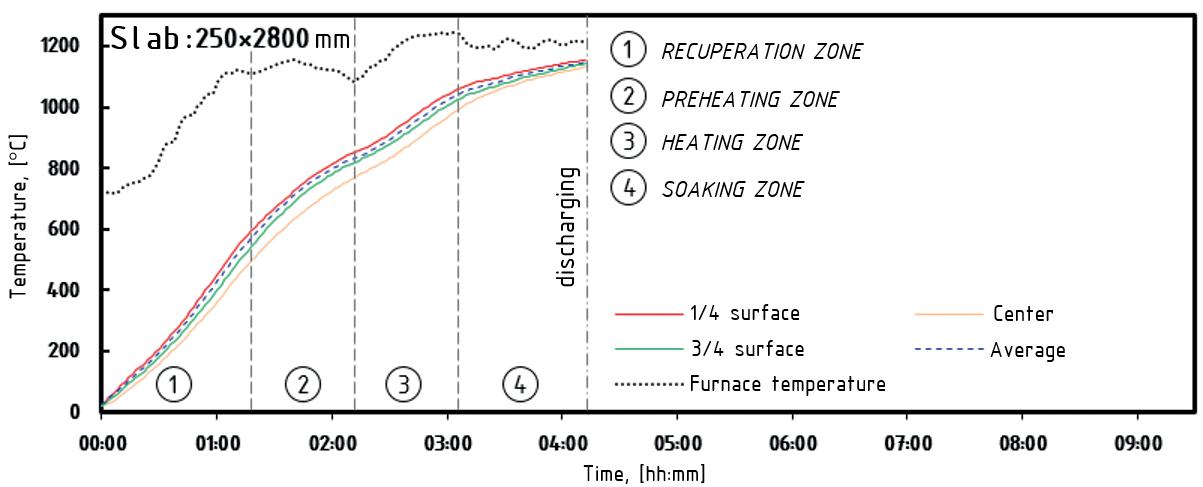
Earlier in work [15] it was shown that when heating a 250 mm slab in the old furnace no. 2, the maximum temperature gradient was for a long time within 250-300°C, and at the exit of the furnace the slab had a sensitive temperature difference in cross section. Figure 5 shows an industrial schedule of heating slabs cross-section 250×2800 mm in the new furnace № 3. Analysing thermal and technical data of slab heating for heavy plate production using the new furnace, it should be noted that the slab temperature uniformity distribution during the whole heating period is essential. When heating slabs cross-section 250 × 2800 mm in the new furnace, maximum temperature gradient does not exceed 130°C (Figure 5). The peak values of temperature gradients are situational in nature and appear only for a short period of time and at times of adaptation of the control model of heating for each specific slab in the active zones of the furnace. For slabs with a thickness of 250 mm the most critical time is the time interval between approx. 90 and 120 minutes during which the upper and lower surfaces of the slab are actively heated. During the last 20 minutes in the soaking and equalising phase, the temperatures at ¼, ½ and ¾ of the slab thickness reach a maximum gradient of no more than 20°C. As can be seen from the graph in Figure 5, heating of 250×2800 mm slabs to a given temperature of 1150 °C takes no more than 4.5 hours. It is possible to reduce the heating time, however, with a certain decreasing of quality.
A similar schedule for heating 400×2800 mm slabs is shown at Figure 6. For large cross-section slabs with a thickness of 400 mm, the heating time is
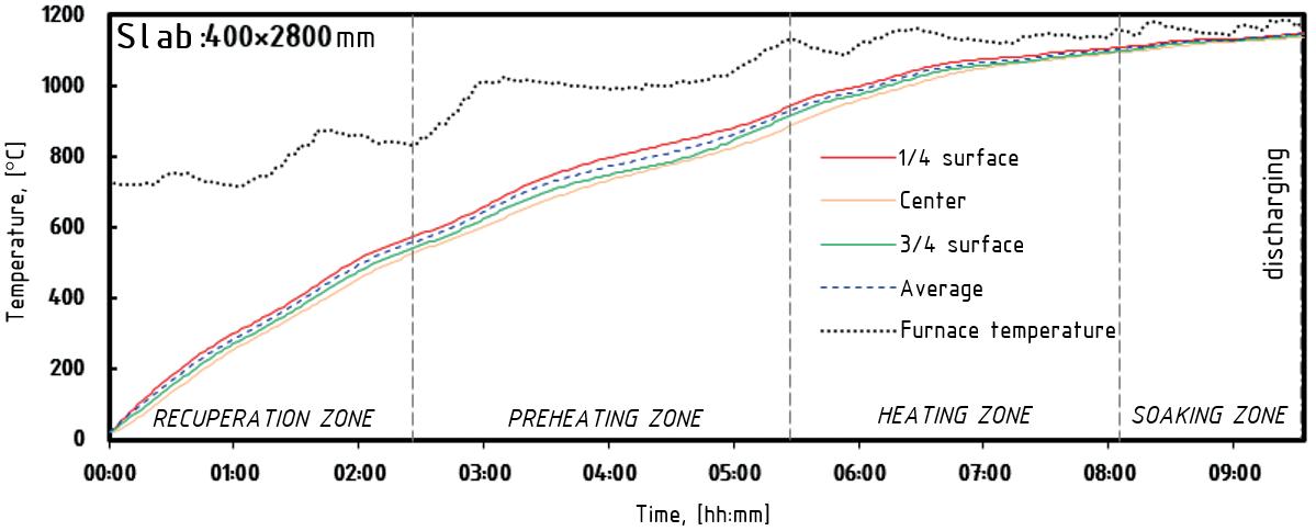
34 Furnaces International September 2023 www.furnaces-international.com
Figure 5. Heating curves of a 250×2800 mm slab in the new reheating furnace no. 3
LIFE
TECHNICAL FOCUS
Figure 6. Heating curves of a 400×2800 mm slab in the new reheating furnace no. 3
OF A FURNACE
in the range of 9-10 hours. The heating time can be reduced to 8 hours, but also with a decrease in the quality of heating towards an increase in the temperature gradient across the thickness of the slab. It should be noted that the temperature increases smoothly in the heating curves at ¼, ½ and ¾ of the slab thickness. From the peaks of the upper furnace temperature curve, the discreteness of the adaptation adjustments of the furnace heating control model can be evaluated.
Heavy plate temperature profile
The DanSteel 4200 Rolling Complex is equipped with twelve control pyrometers and three termo scanners that measure the temperature of 100% of the top surface of the plate at reference points in the heavy plate production process. The data obtained can be used to accurately and in real time evaluate the temperature uniformity of the plate in width and length direction.
As an example, Figure 7 shows the results of a scan of the surface temperature of 120 mm thick rolled steel heavy plate after deformation stage is completed and before the start of final cooling in
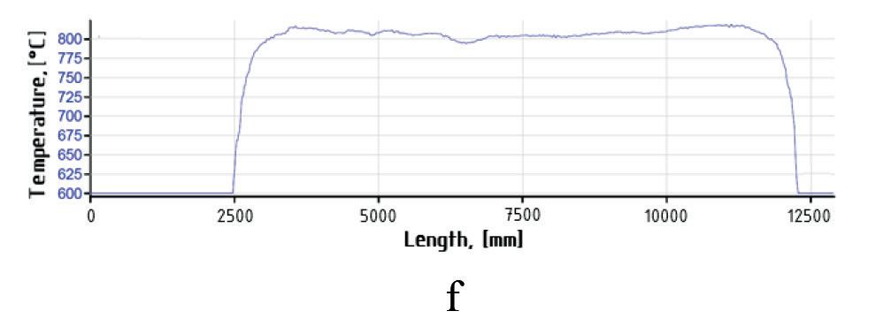
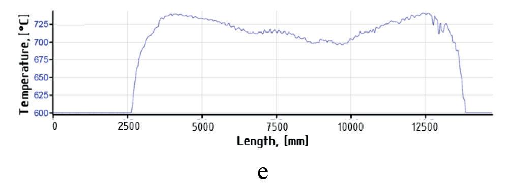
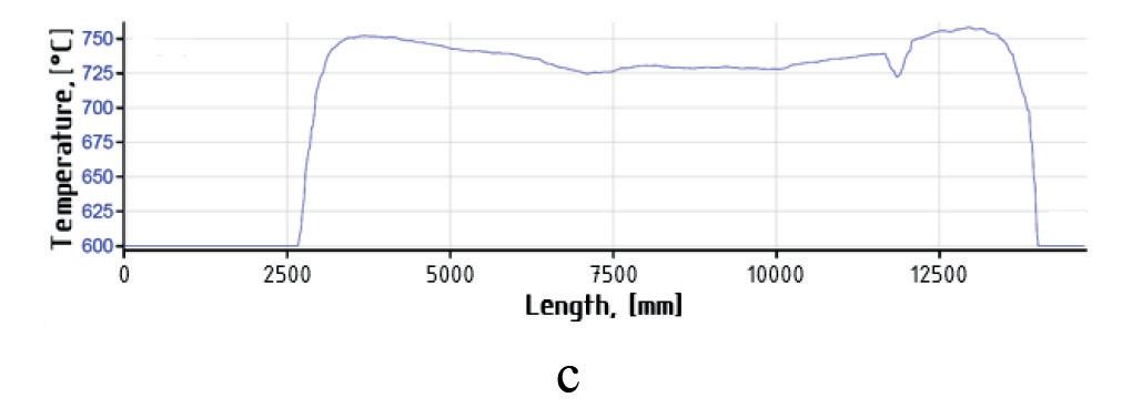
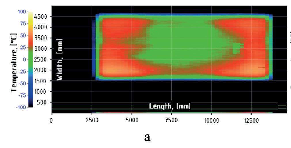
an accelerated cooling unit. Two states of temperature gradients occurring during production are considered: uneven heating and uniform heating. Figure 7a shows the temperature field of a plate with expressed temperature irregularity. The main reason for the marked irregularity in the temperature field of the rolled plate is non-optimal modes of heating of the slab. It can be seen that the central part of the plate has the temperature specified by the technology, while the head and tail overheated by 50-60°C relative to the specified temperature at a maximum permissible deviation of not more than 30°C. Figure 7b shows the temperature field of a plate with a high degree of uniformity. Approximately 95% of the surface of such a plate is at the process-specified temperature with a deviation of ±3°C. The maximum temperature gradient does not exceed 10°C.
The temperature profiles of the top (Figure 7c and Figure 7d) and bottom (Figure 7d and Figure 7e) rolled surfaces, obtained from control pyrometers, show that the nature of the temperature non-uniformity is repeated on the upper and lower surfaces of the plate. In the
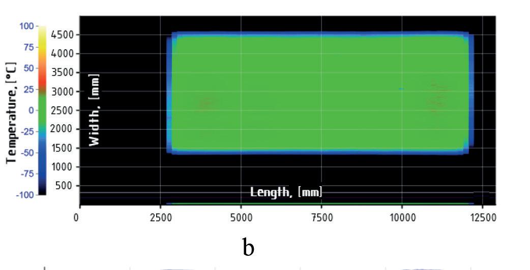
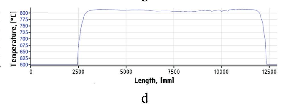
first “non-optimal” case the temperature gradient of the top surface reaches about 76°C, and on the bottom surface: - 54°C. In the case of uniform heating, the gradient of the top surface of the plate does not exceed 3-6°C and the bottom surface: 5-11°C.
Preventive Maintenance System
The DanSteel new walking beam furnace is also equipped with an innovative maintenance support tool named SMS-Prometheus PMS (stands for Preventive Maintenance System). It basically consists on a software platform collecting and elaborating the data provided by an extended number of sensors strategically placed over several mechanical components of the furnace, with the goal of predicting possible malfunctioning. The monitored equipment include the key handling devices, like the slab charger, the slab extractor or the walking beam system, as well as the hot air recuperator, the combustion air fans of the main components of the water treatment fan. The software algorithm is able to extrapolate some data from the sensor measurements to assess the key perfor-
35 Furnaces International September 2023 www.furnaces-international.com
TECHNICAL FOCUS
Figure 7. Temperature gradients of 120 mm heavy plate, produced using TM+ACC modes: a, b - top surface thermoscanner data; c, d - temperature profile of top surface from pyrometer; e, f - temperature profile of bottom surface of plate from pyrometer
LIFE OF A FURNACE
mance trends of the related component and anticipate the necessity of intervention for maintenance or repair before any actual damage happens.
In the example of Figure 8 the trends are shown that correlate the walking beam movement and the cylinders pres-
References
sure to the slab load inside the furnace. Any significant deviation in respect to the foreseen pattern denotes a movement anomaly and will trigger a notification to the control system, that allows the plant maintenance team to act preventively in view of a potential failure.
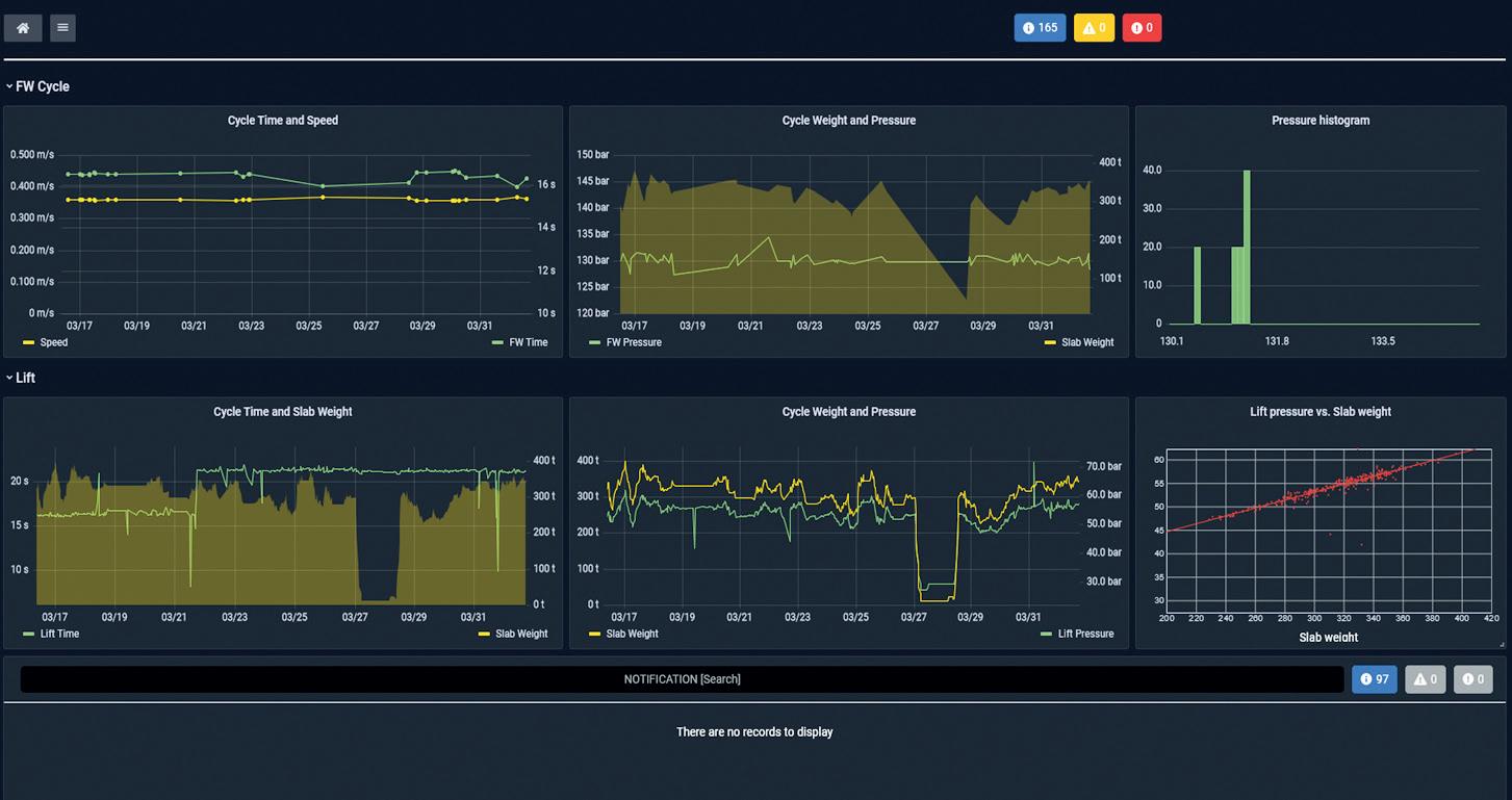
Conclusion
A new walking-beam reheating furnace with a designed productivity of up to 100 t/h has been put into operation at DanSteel rolling complex 4200. This allowed expanding the range of heated large-size slabs with a maximum cross-section of H×B 400×2800 mm and weighing up to 63 tonnes. The implemented project has provided increased uniformity of heating along the thickness, width and length of slabs with average maximum values of temperature gradients in the three directions not exceeding 30°С and reduced consumption of natural gas to the level of 31-32 m3/t of finished product. More uniform heating of slabs ensured improved temperature field uniformity of rolled heavy plates. The constructive possibility of a partial transition to the use of hydrogen instead of natural gas was taken into account. �
1. Sarkits I., Bokachev Y., Goli-Oglu E. Production of heavy plates on the rolling mill 4200 DanSteel A/S // Stahl und Eisen. 2014. №4. P. 57 – 61.
2. Tamura I., Sekine H., Tanaka T. Thermomechanical Processing of High-strength Low-alloy Steels // Butterworth-Heinemann, 2013. 256 p.
3. Gorni A., Silveira J. Accelerated Cooling of Steel Plates: The Time Has Come // Journal of ASTM International. 2008. Vol. 5, No. 8. Р. 358-365.
4. Matrosov, Y.I. Complex microalloying of low-pearlite steels subjected to controlled rolling. Met Sci Heat Treat. No. 28. 1986. p. 173–180.
5. Subramanian S. V., Zhu G., Klinkenberg C., Hulka, K. Ultra-Fine Grain Size by Dynamic Recrystallization in Strip Rolling of Nb Microalloyed Steel // In Materials Science Forum. 2005. Vols. 475–479. P. 141–144.
6 . Hong S.C., Lim S. H. Inhibition of Abnormal Grain Growth during Isothermal Holding after Heavy Deformation in Nb Steel // ISIJ International. 2002. Vol. 42. №12. P. 1461–1467.
7. Hulka K., Kern A., Schriever U. Application of Niobium in Quenched and Tempered High-Strength Steels // Materials Science Forum. 2005. Vols. 500–501. P. 519-526.
8. Sellars С.М., Whiteman J.A. Recrystallization and Grain Growth in Hot Rolling // Metal Science. 1979. № 13. P. 187-194.
9. Tamehiro H., Yamada N., Matsuda H. Effect of the Thermo-Mechanical Control Process on the Properties of High-strength Low Alloy Steel // Transactions of the Iron and Steel Institute of Japan. 1985. Vol. 25, Issue 1. P. 54-61.
10. Liang Sh., Fazeli F., Zurob H. S. Effects of solutes and temperature on high-temperature deformation and subsequent recovery in hot-rolled low alloy steels // Materials Science and Engineering: A. 2019. Vol. 765. P.138324.
11. Yada H. Prediction of Microstructural Changes and Mechanical Properties in Hot Strip Rolling. // Proceeding of the International Symposium on Accelerated Cooling of Rolled Steel. Winnipeg. Canada. 1988. P. 105-119.
12. Roberts W., Sandberg A., Siweski Т., Werlefors T. Prediction of Microstructure Development during Recrystallization Hot Rolling on Ti-V-steels. // ASM HSLA Steels Technology and Applications Conference. Philadelphia, USA. 1983. P. 35-52.
13. Wang R., Garcia C.I., Hua M., Cho K., Zhang H., Deardo A.J. Microstructure and precipitation behavior of Nb, Ti complex microalloyed steel produced by compact strip processing. // ISIJ international. 2006. Vol. 46, № 9. P. 1345-1353.
14. Innovation in combustion process. // SMS group: [official site]. URL: https://www.sms-group.com/en-gb/insights/all-insights/innovation-in-combustion-process (date of review 2023-03-20).
15. Tretyakov V. A., Bokachev Yu. A., Filatov A. N., Goli-Oglu E. A. Development of a digital twin of the process of controlled rolling of thick plate from high-strength low-alloy steels. Message 1. Simulation of slab reheating in continuous furnace with a prediction of austenite grain size before rolling. // Problems of ferrous metallurgy and materials science. 2022. №. 2. P. 30-40.
36 Furnaces International September 2023 www.furnaces-international.com
Figure 8. Dashboard Handling – monitoring of the Walking Beam system
TECHNICAL FOCUS
LIFE OF A FURNACE


GLASS SERVICE Are you looking to the future for CO2 reduction? Then look no further than FIC... Tying Technology Together The eventual solution is hybrid fur naces operating at up to 80% electricity BUT small steps increase electric boost to reduce the CO2 then superboost. GS and FIC are THE companies to supply CFD modelling of your flexible future fur naces. FIC ...the pathway to a cleaner future www.fic-uk.com +44 (0) 1736 366 962 The World,s Number One in Fur nace Technology FIC (UK) Limited Long Rock Industrial Estate, Penzance, Cornwall TR20 8HX, United Kingdom


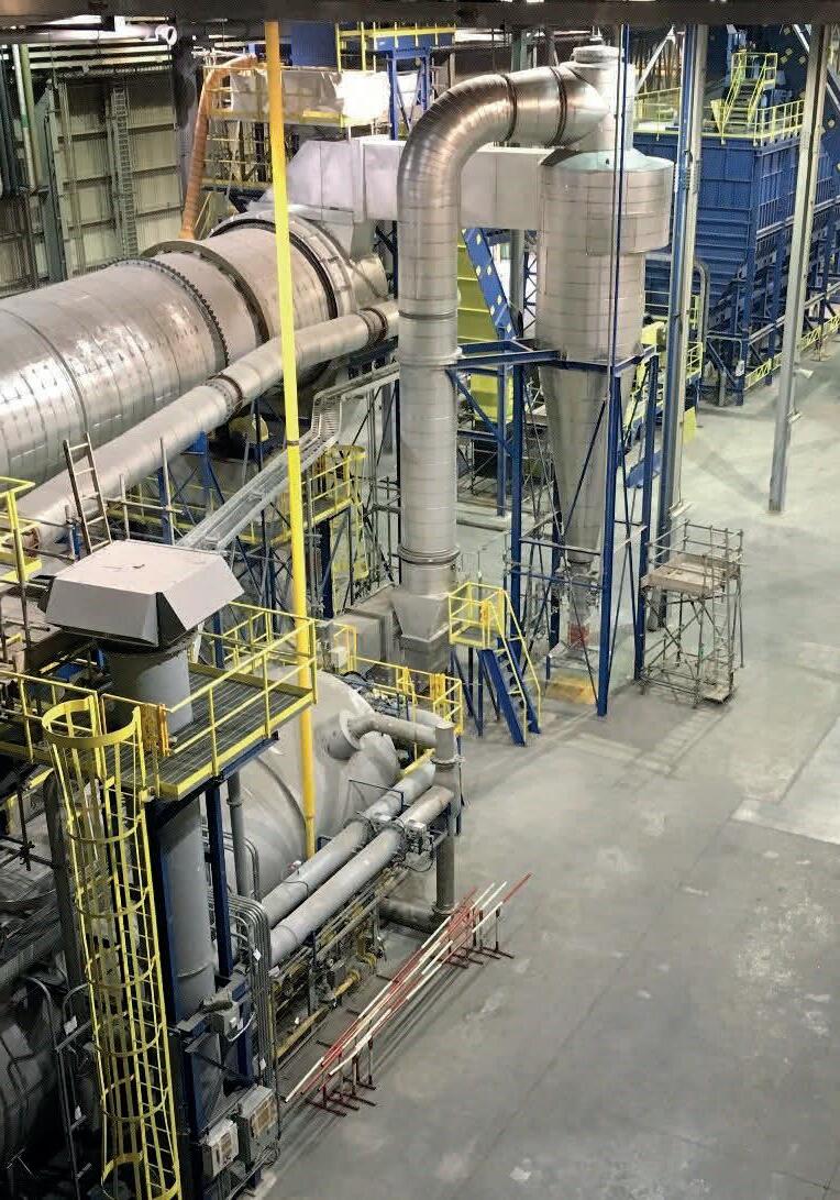
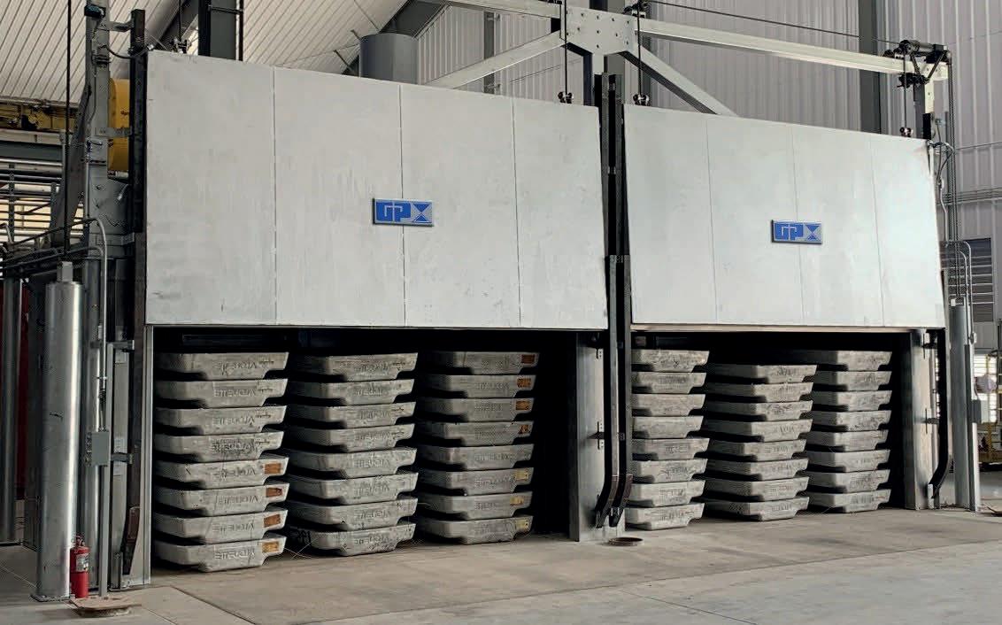


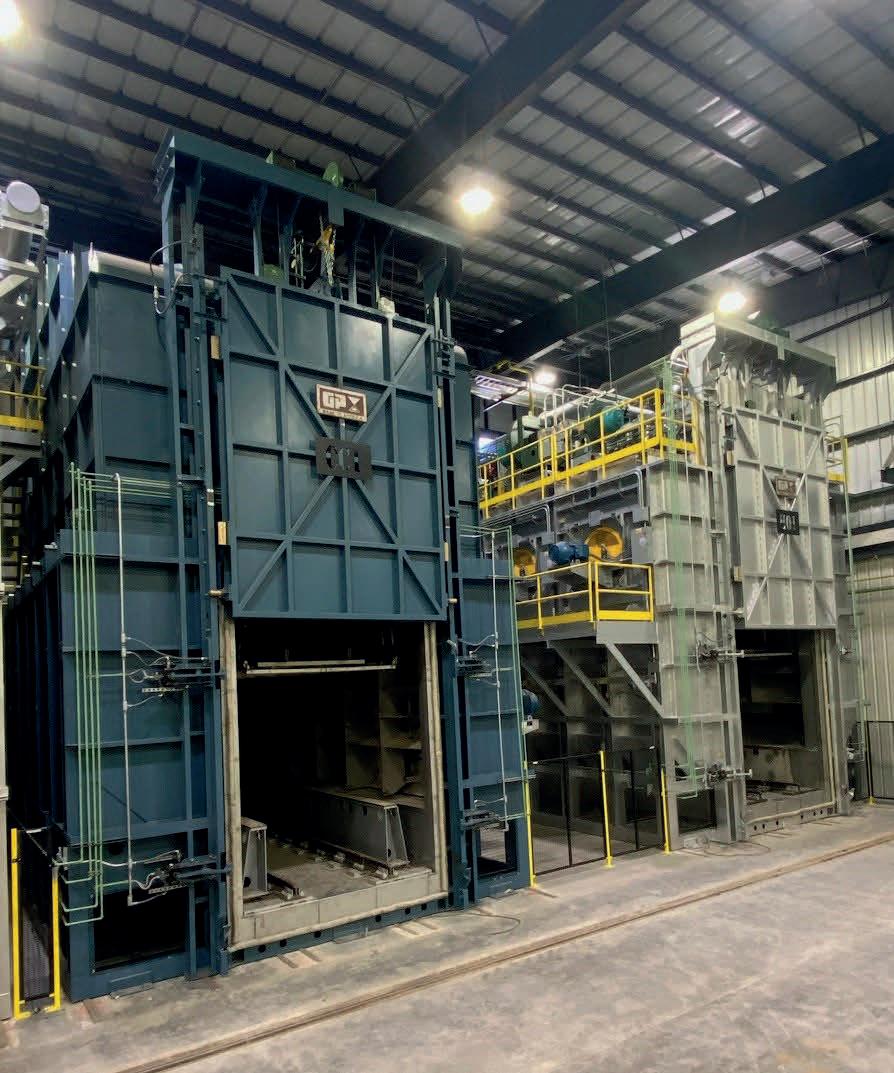
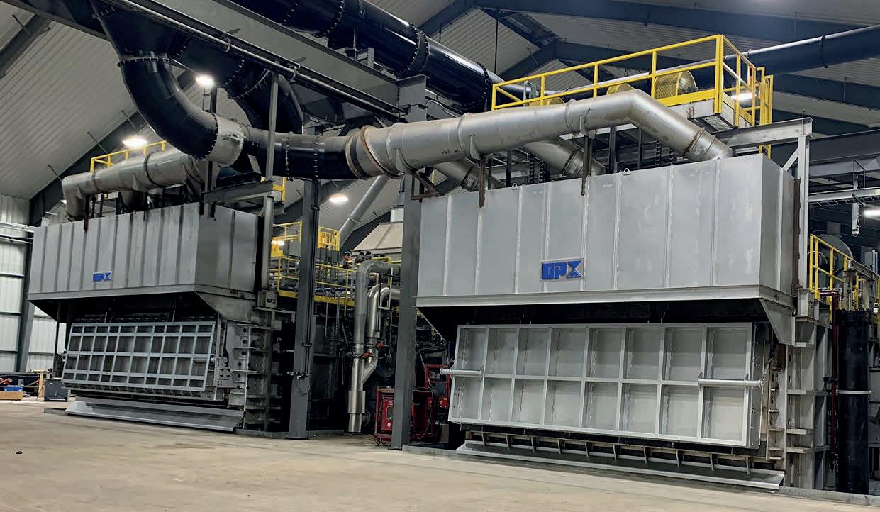
ST. LOUIS, MISSOURI, USA 800 325 7075 | www.gillespiepowers.com | 314 423 9460 ✓SINGLE CHAMBER / MULTI CHAMBER FURNACES ✓SCRAP DECOATING SYSTEMS ✓TILTING ROTARY MELTING FURNACES ✓SCRAP CHARGING MACHINES ✓LAUNDER SYSTEMS ✓CASTING / HOLDING FURNACES ✓HOMOGENIZING OVENS ✓COOLERS ✓SOW PRE-HEATERS ✓REPAIR & ALTERATIONS
