COMPANY PROFILE DECARBONISATION EVENT REVIEW INDUSTRY UPDATES www.furnaces-international.com - MARCH 2023 www.furnaces-international.com - MARCH 2023
Editor: Nadine Bloxsome nadinebloxsome@quartzltd.com Tel: +44 (0) 1737 855115
Editorial Assistant: Zahra Awan Tel: +44 (0) 1737 855038 zahraawan@quartltd.com

Production Editor: Annie Baker
Sales Manager/Advertisement


production: Esme Horn esmehorn@quartzltd.com


Tel: +44 (0) 1737 855136


Subscriptions: Jack Homewood subscriptions@quartzltd.com
Managing Director: Tony Crinnion
Furnaces International March 2023 www.furnaces-international.com 30 30
Published by: Quartz Business Media Ltd, Quartz House, 20 Clarendon Road, Redhill, Surrey RH1 1QX, UK. Tel: +44 (0)1737 855000. Email: furnaces@quartzltd.com www.furnaces-international.com Furnaces International is published quarterly and distributed worldwide digitally © Quartz Business Media Ltd, 2023 C FRONT COVER: SMS Group 6 25
GLOBAL FURNACES
2 Global Furnaces News
6 Phoenix: From the flames... monitoring innovations
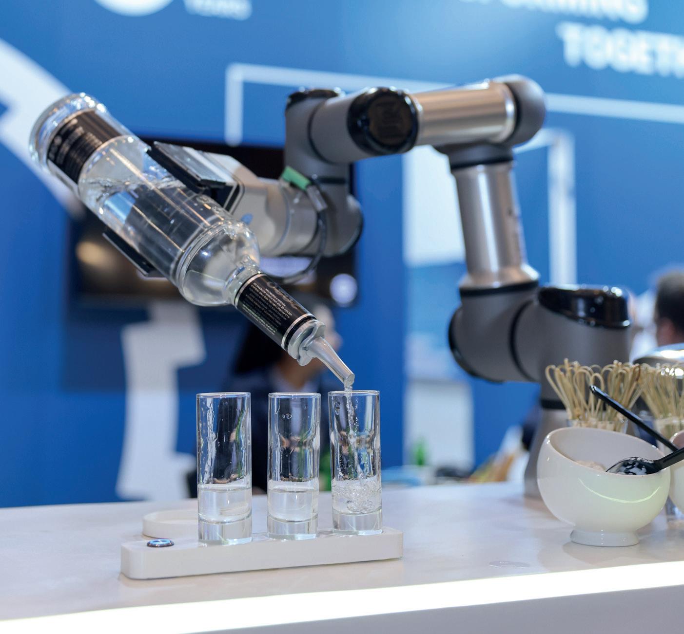
25 Event review: Glassman Europe 2023 Making the Furnace of the Future
30 Ametek Global: How combining IMAGEPro Glass with NIR-B-2K thermal imaging and Lancom 4 can improve carbon footprint and reduce emissions
LIFE OF A FURNACE
34 Life of a Furnace News
36 Heat Treat Today: Radiant Tubes: Exploring your options
44 The rise and fall of a blast furnace
GREENER FURNACES
50 Greener Furnaces News
54 Decarbonising regenerative glass furnaces
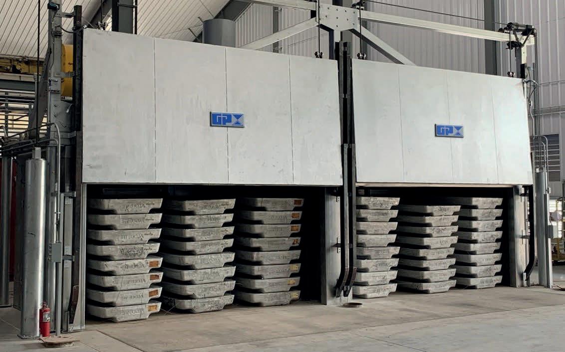
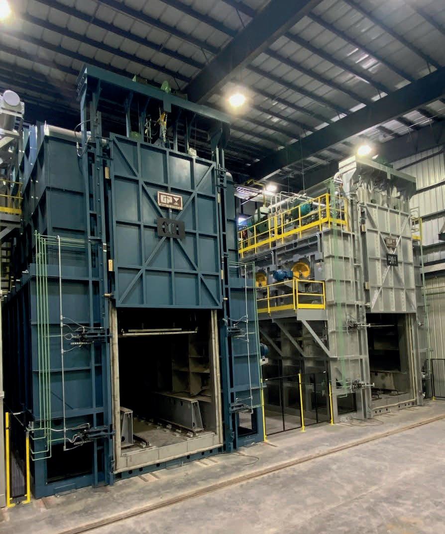
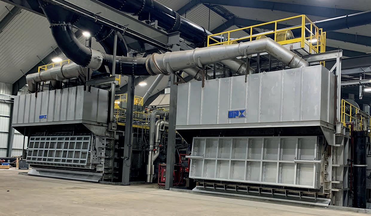
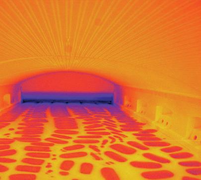
64 Decarbonisation of secondary aluminium melting
As I’m writing this, the weather here in the UK can’t seem to make up its mind as to whether it is officially spring yet, but with the clocks poised to go forward at the end of this month, longer days and lighter evenings are on the horizon again.
We are always a few steps ahead in publishing and looking towards the next few months, so the months can fly by, but it seems the furnaces industry is also not standing still at the moment.

After a lively Glassman Event was recently held in Istanbul, Turkey, this issue features a host of articles featuring the efforts going into decarbonising glass furnaces.
There is also a fascinating historical look at an iconic UK landmark, Redcar furnace, which after close to five decades of service, was demolished in late 2022.
I hope you enjoy this issue!
Nadine Bloxsome,
Editor,
Furnaces International, nadinebloxsome@quartzltd.com

1 Furnaces International March 2023 www.furnaces-international.com
© Quartz Business Media Ltd, 2022
Welcome to the March issue of Furnaces International.
CONTENTS AND COMMENT
French glassmaker makes furnace investment
French glass manufacturer Waltersperger is to expand production as part of a furnace investment. The company based in Blangy-sur-Bresle, Normandy is to move to modern, expanded facilities on the outskirts of the town later this year.
Its current production facility is outdated and located in the centre of town, which was caused difficulties with truck movements.
As part of the move it has invested in a new 4 tonne furnace from Italian group Falorni Tech as well as two new production lines. It currently operates seven 500kg furnaces working in parallel with four production lines.
Waltersperger President, Stephanie Tourres, told Glass International, that the move to the new facility will enable it to make glass continuously in an automatic process.
“The current semi-automatic process we have to load the glass to enable us to work for seven hours a day. Once we move to an automatic process we will have a continuous flow of glass which means we can work for 24 hours a day. This will enable us to expand the process and to touch upon new markets and allow us to propose to clients an in-between service where we can serve medium sized runs.”
The structure of the new building is already in place, with the next move to work on the interior of the building. The aim is to open the building by the end of the year.
NEWS GLOBAL FURNACE 2 Furnaces International March 2023 www.furnaces-international.com
Danieli
Danieli to supply patented tech to Japanese EAF
Japanese flat-steel producer Shinkansai Steel Co., Ltd has announced plans to implement Italian plant supplier Danieli’s Q-One technology on the 74-ton tapping capacity electric arc furnace in operation at its Sakai plant.
Designed by Danieli Automation, Q-One uses the latest digital power electronics technology to maintain the EAF power-factor values close to unity.
The power-feeding system, that will be installed at Sakai, will have a five-unit configuration with a total maximum power of 54,6 MVA.
By controlling electrical current, voltage and frequency during melting to maintain optimal levels according to changes within the electric furnace, the consumption of electricity and electrodes will be reduced, says Danieli, leading to energy and operating cost savings in the steelmaking process.
The project is expected to be completed by the fall of 2024.

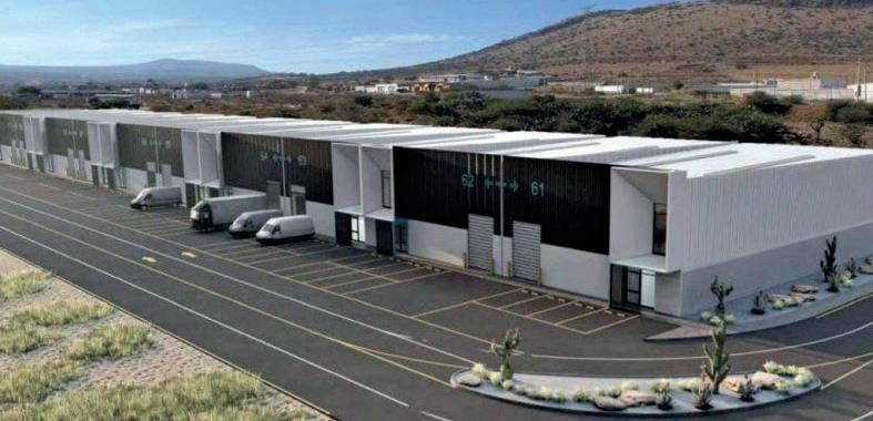
Furnace professionals form Mexican alliance

Furnace specialists M-Glass Factory Services (MGFS) and Excelsius have formed an alliance for the Mexican and South American glass production markets.
The two companies, which specialise in furnace draining, drilling, controlled cooling down, controlled heating up, cullet fill and thermal cleaning of regenerators.
The Excelsius-MGFS team is capable of heating up a furnace, with expansion control, bolt adjustment, cullet fill and furnace operation until glass reaches the machines, all in one hand.
The partnership has equipment domestically in Mexico as well as
qualified staff based in the country.
It has recently installed a new warehouse and offices in San Juan Del Rio Business Park in the state of Queretaro, located centrally for the Mexican glass industry.
NEWS GLOBAL FURNACE 3 Furnaces International March 2023 www.furnaces-international.com
UK manufacturing firm acquires major global
A UK manufacturing company’s growth plans have taken an exciting leap forward with the acquisition of a state-of-the-art product line from Europe.
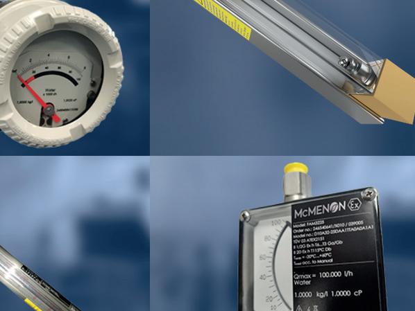
A range of Variable Area (VA) Flowmeters will now be manufactured in Workington, Cumbria, after McMenon Engineering Services Ltd was chosen by global technology company ABB to make the VA flowmeter product portfolio that had been produced by ABB in Germany.
Following the acquisition, McMenon, under a supply partnership agreement, will continue to supply VA meters carrying the ABB brand and the meters remain part of ABB’s product offering.
McMenon, a worldwide manufacturer and supplier of quality flow and temperature measurement instrumentation, and ABB have a long-standing partnership.

McMenon CEO Anand Puthran said: “I take great pride in the fact that McMenon have been considered by ABB as a reliable new home for the VA flowmeter product portfolio.
(Image right: McMenon CEO Anand Puthran)
“The fact that we were chosen over other global competitors is testament to the quality of our product engineering and manufacturing capabilities and reputation for innovation.”
Complimenting the workforce, Chief Operations Officer Shiby Bernard said: “In the span of a few weeks, McMenon’s brilliant team successfully transferred the entire product line to Workington, UK.
“This acquisition will create stability, growth and more opportunities for our workforce and new jobs.”
She added: “Through proactive endeavours and the brilliant support of its team, McMenon is helping to secure its own future as we emerge from the after-effects of the pandemic and Brexit.”
The overall deal is set to create new jobs, increasing McMenon’s global workforce by almost a third.
With this acquisition, McMenon, already a highly recognised name in the global flowmeter and temperature instrumentation market, will now be placed among the top global manufacturers of VA flowmeters. ABB customers will see no difference and can expect the same product quality they are used to.
NEWS GLOBAL FURNACE 4 Furnaces International March 2023 www.furnaces-international.com
global product line
Mr Puthran added: “This win for McMenon is also a win for UK manufacturing. Not often do we see manufacturing operations being transferred into the UK, especially from countries like Germany which are the best in the business.
“We have recently celebrated 75 years of manufacturing heritage in West Cumbria and we are proud to keep flying the flag for UK manufacturing.”
NEWS GLOBAL FURNACE 5 Furnaces International March 2023 www.furnaces-international.com
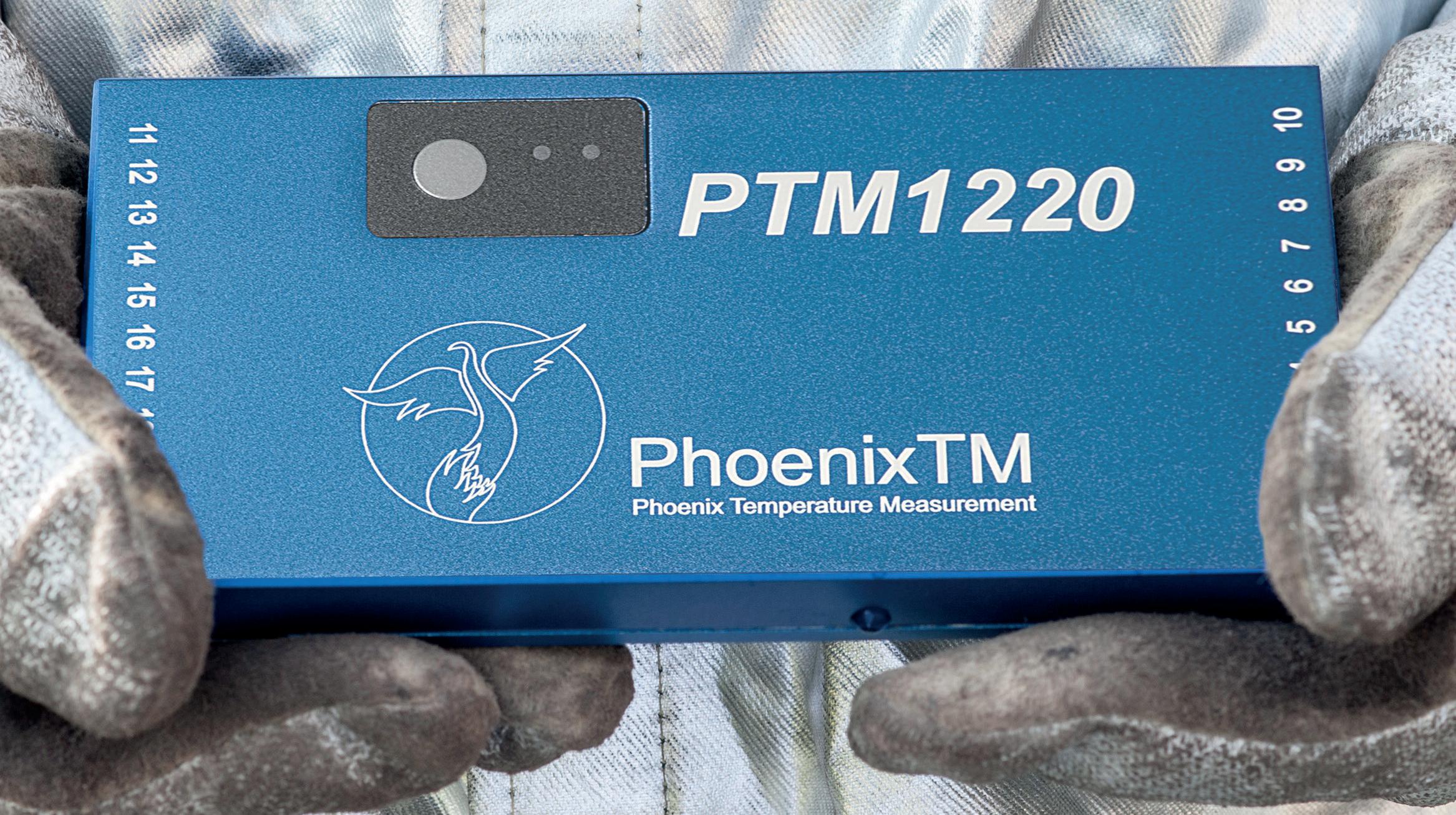
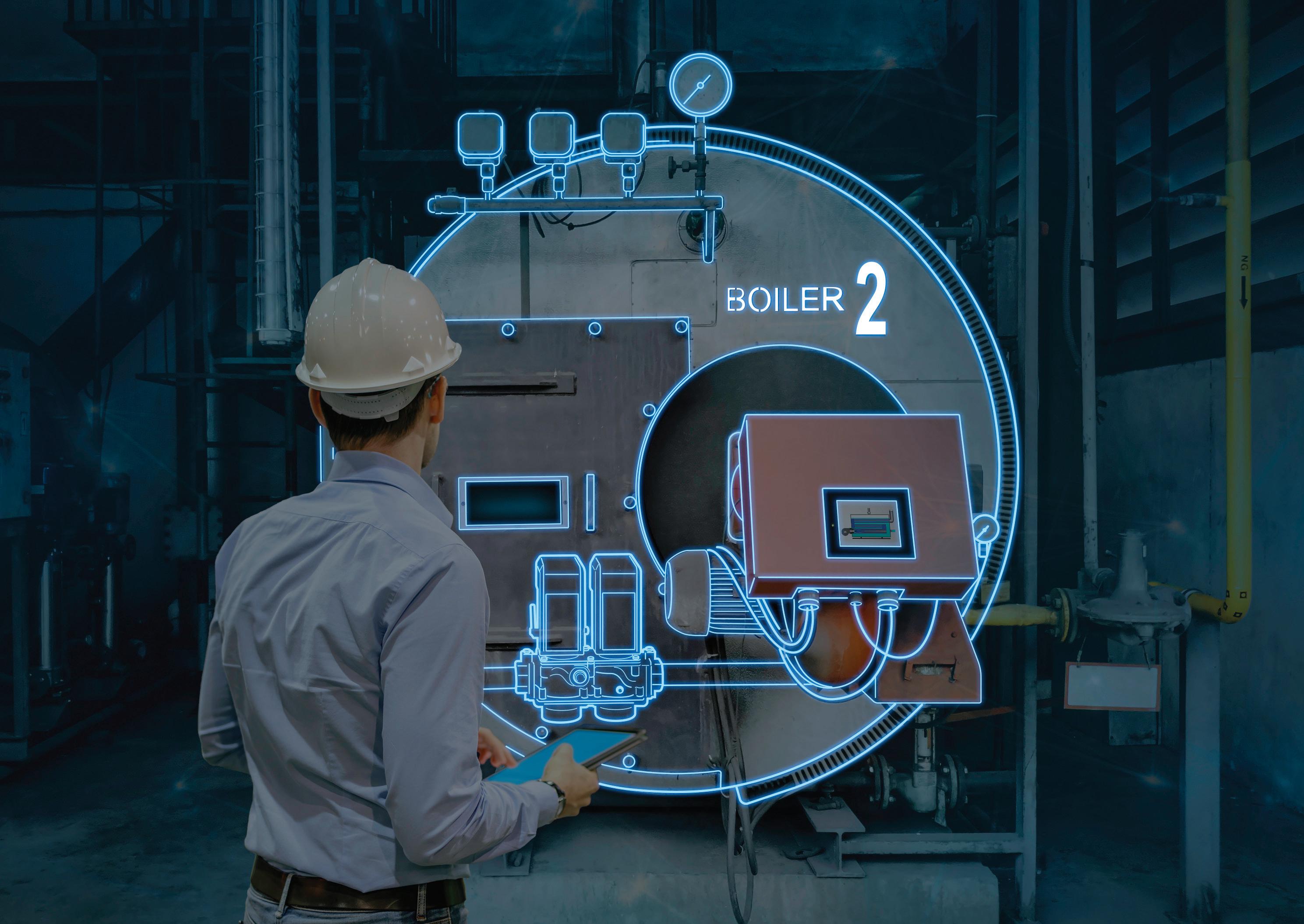
FROM THE FLAMES ... MONITORING INNOVATION
Zahra Awan* Spoke with Dr Steve Offley** on the past, present and futures of the PhoenixTM company. With the introduction of new technology, the transition to Industry 4.0, for the furnaces industry, becomes one of many possibilities.
1.Can you give a brief history of the PhoenixTM company –how was it founded and why?


PhoenixTM “Phoenix Temperature Measurement” was founded in 2010 by a small, experienced team of individuals who had previously worked together for a well-known temperature monitoring company which had been acquired by a large American corporation providing industrial handheld measurement systems. From humble beginnings PhoenixTM has grown over the last 13 years with its team being strengthened by other experienced personnel from the same original company including myself (over 20 years), extending market and technology knowledge further.
*Editorial Assistant
**Product Marketing Manager at PhoenixTM

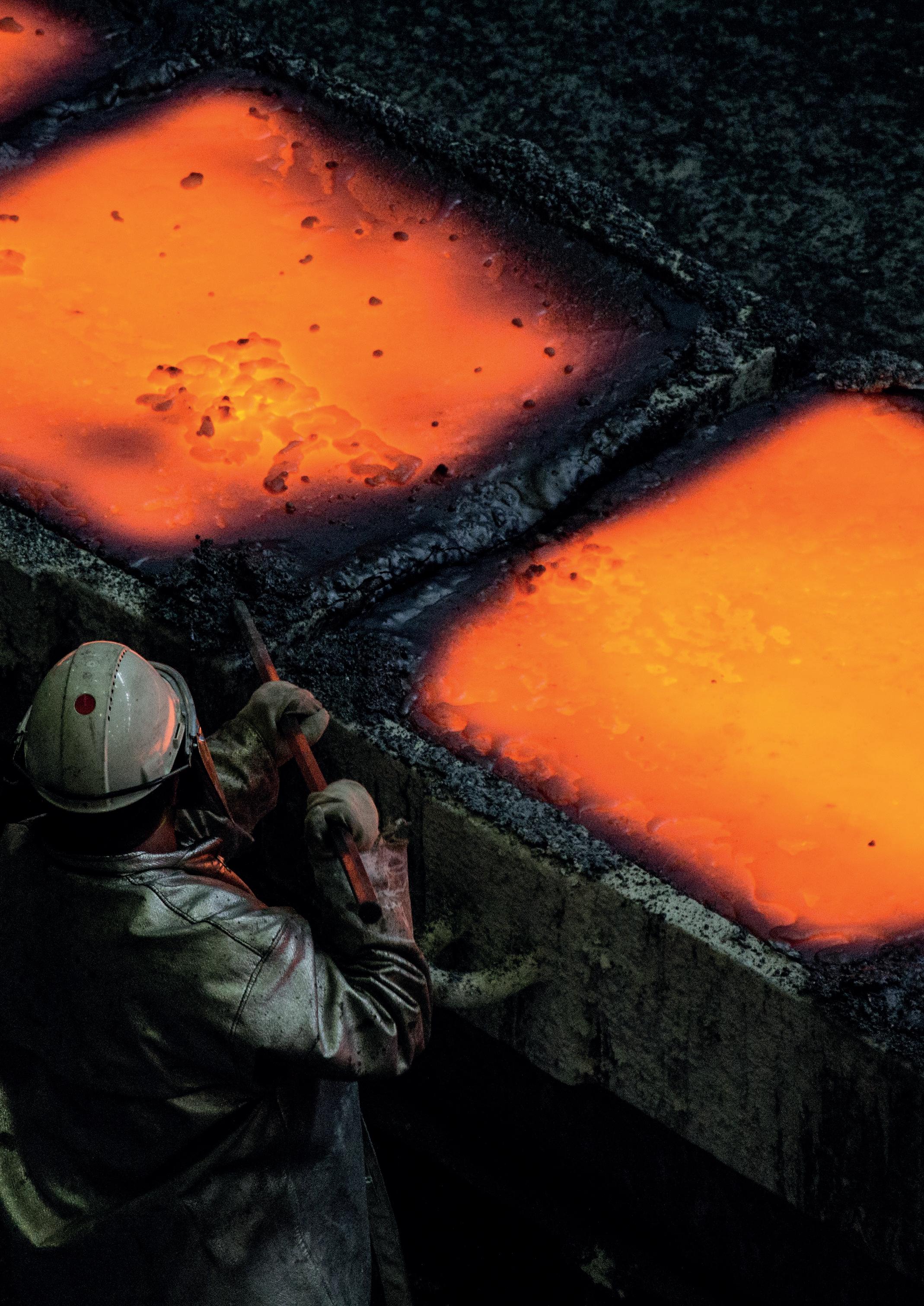
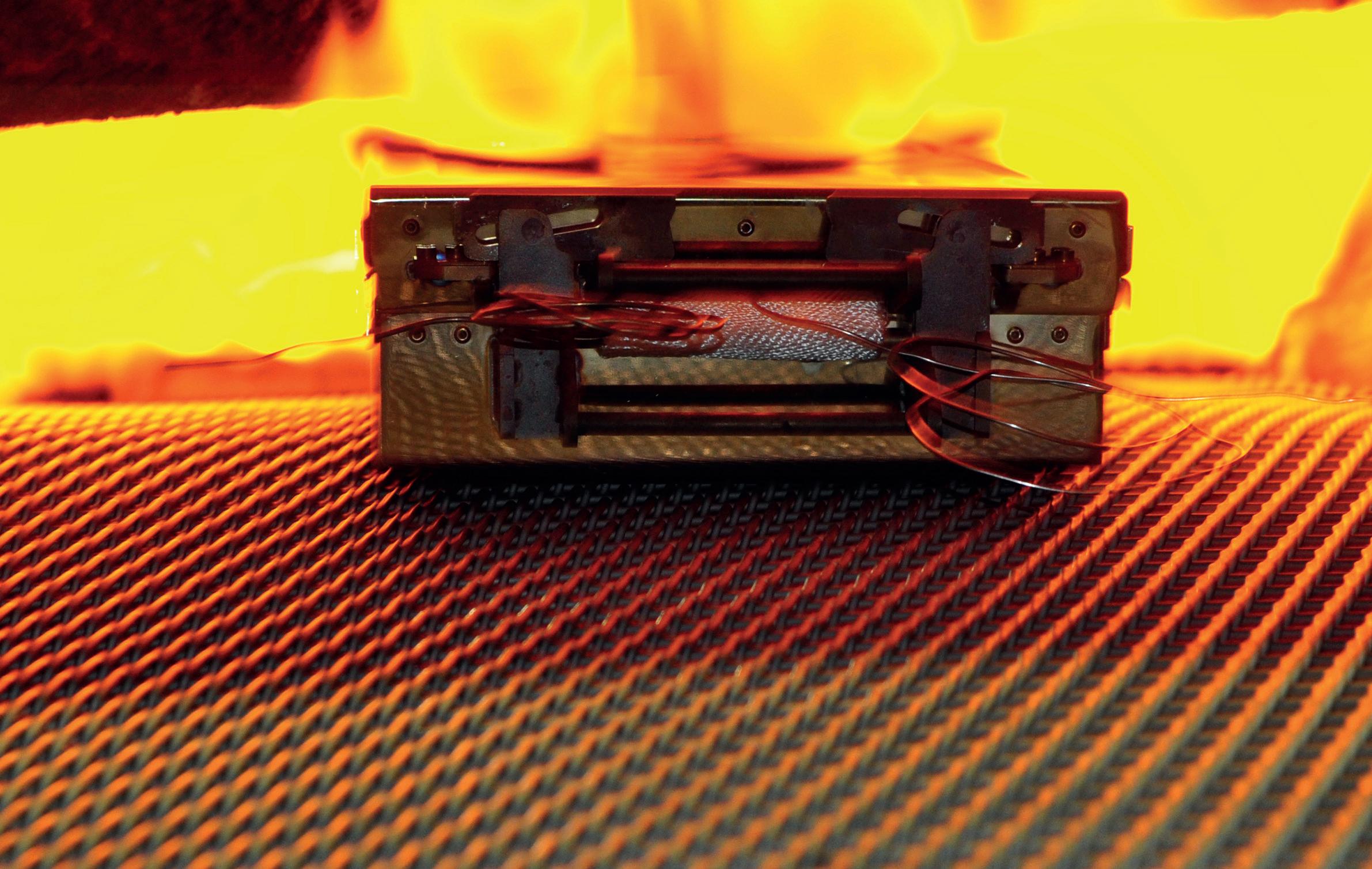
As you can see by the name chosen for the company the vision of PhoenixTM was to bring back new life to an important industrial technology. It seemed also fitting as the image of the phoenix rising from the flames/ashes is comparable to the PhoenixTM system emerging from the flames of a heat treat


GLOBAL FURNACES 6
Furnaces International March 2023 www.furnaces-international.com
furnace.
The company prides itself on a strong ethos to innovate and provide added value in terms of performance, and extended application suitability. We offer a value solution with informed market knowledge and quick efficient responsive service and support globally. Small enough to care, yet large enough to support the customer base. We strive to exceed customer expectations, offering that personal touch that makes a difference, often missing from larger corporate operations. As our tag line states……..where experience counts!


2. What is the technical principle of Thru-process temperature monitoring solutions offered by PhoenixTM and how do they benefit over traditional methodology?


In any thermal processing there is a need to monitor the temperature of the product being processed in the furnace. The product temperature is often critical to important metallurgical transitions to give material specific properties essential for its intended use. Traditional temperature monitoring methods don’t always give the desired information.
Furnace control Thermocouples provide only a snapshot of the furnace temperature at a specific location but not the product temperature. IR sensors or cameras are generally fixed point also, need line of sight, and only offer approximate average
GLOBAL FURNACES 7 Furnaces International March 2023 www.furnaces-international.com
surface temperature measurement. Trailing thermocouples can give product temperature measurement continuously through a furnace but use is difficult, if not impossible, and unsafe in many applications. The method is not feasible if the heat treat process is modular and generally impossible during production flow.
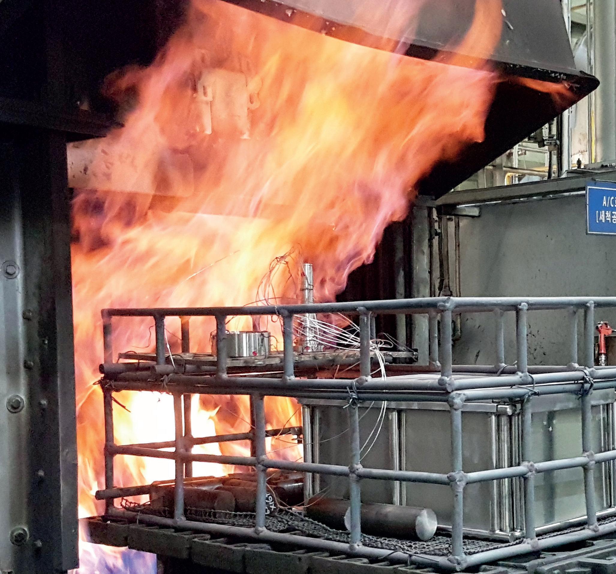
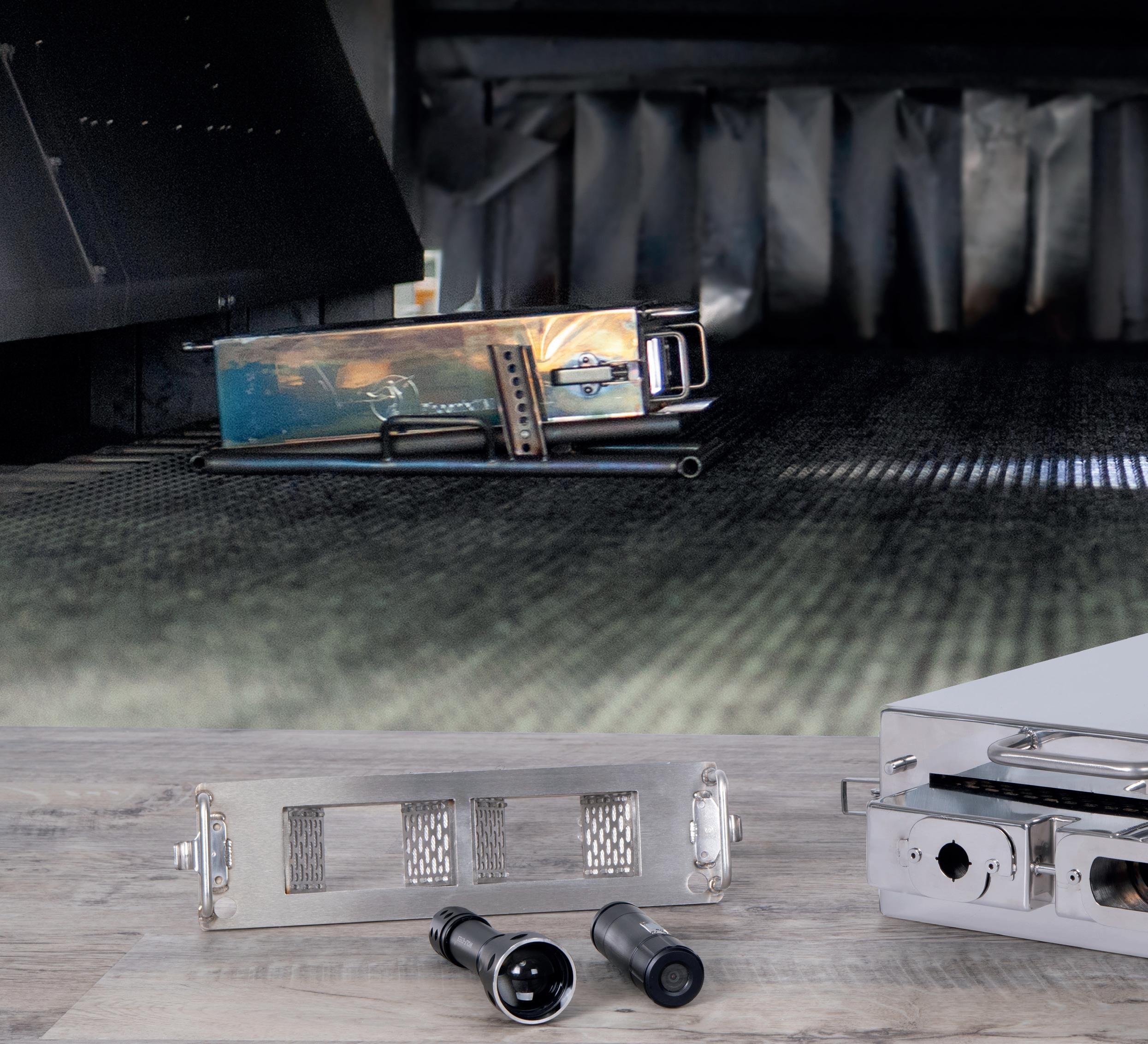
Thru-process temperature profiling is a simple concept but gives you product temperature information through the complete furnace with efficiency and safety. The data logger measuring product and or environment temperature is sent through the entire furnace process measuring temperature continuously during the journey. The data logger is protected from the potentially harmful process conditions (Heat, Gases, Pressure, Water Quench, Oil Quench) with a process specific thermal barrier design. The shape, form , material and protection technology is matched to the specific application challenges.
At the end of the process a temperature profile is obtained which is basically a thermal fingerprint of what temperature
GLOBAL FURNACES 8 Furnaces International March 2023 www.furnaces-international.com
Data Logger


GLASS SERVICE Tying Technology Together Help the planet existing chnology educe CO2 with: l Boost l More boost l Electric forehearth l Superboost l Hybrid ur naces ble future from Glass Service and FIC The World,s Number One in Fur nace Technology FIC (UK) Limited Long Rock Industrial Estate, Penzance, Cornwall TR20 8HX, United Kingdom www.fic-uk.com +44 (0) 1736 366 962
changes the product experienced during it’s processing. Such information allows full understanding of the process performance to guarantee quality, allow control and optimisation of the process and provide evidence to satisfy accreditation demands such as AMS2750 and CQI-9.
GLOBAL FURNACES 10 Furnaces International March 2023 www.furnaces-international.com
In the current global energy crisis optimisation of any thermal process is critical to manage energy usage costs and carbon emissions. The PhoenixTM system provides an accurate profile of the product temperature, allowing confident optimisation of the furnace program (Set-points and Line speed) to make a signifi-
GLOBAL FURNACES 11 Furnaces International March 2023 www.furnaces-international.com
Oil Quench
cant impact on the running costs of the production line without risk of compromising product quality. Consider the cost saving potential of reducing the furnace set-point by 10-20 °C over an entire annual production cycle.
3. Where is the PhoenixTM solution applied and what specific benefits does it bring to specific industries?
The PhoenixTM system is beneficial in any manufacturing process where the temperature of the process is critical to final properties of the product being processed. The scope and reach of the system is vast, crossing industry boundaries including heat treatment of primary raw metals and finished products, coating of products with thermally cured paint or powder coatings, kiln firing of ceramics and building products even processing of ready
GLOBAL FURNACES 12 Furnaces International March 2022 www.furnaces-international.com
Slab
Go efficiency.
Emerson’s combustion technology provides superior quality and flow performance, enabling you to meet the highest standards of safety and energy efficiency in your industrial burner application.
Learn more at Emerson.com/Combustion
Go Boldly-Go Efficiency_combustion ENGB_185x265mm.indd 1 2/20/2023 1:46:38 PM
to eat foods “cooking”.
The principle is the same but the solution may look very different in size design and complexity.
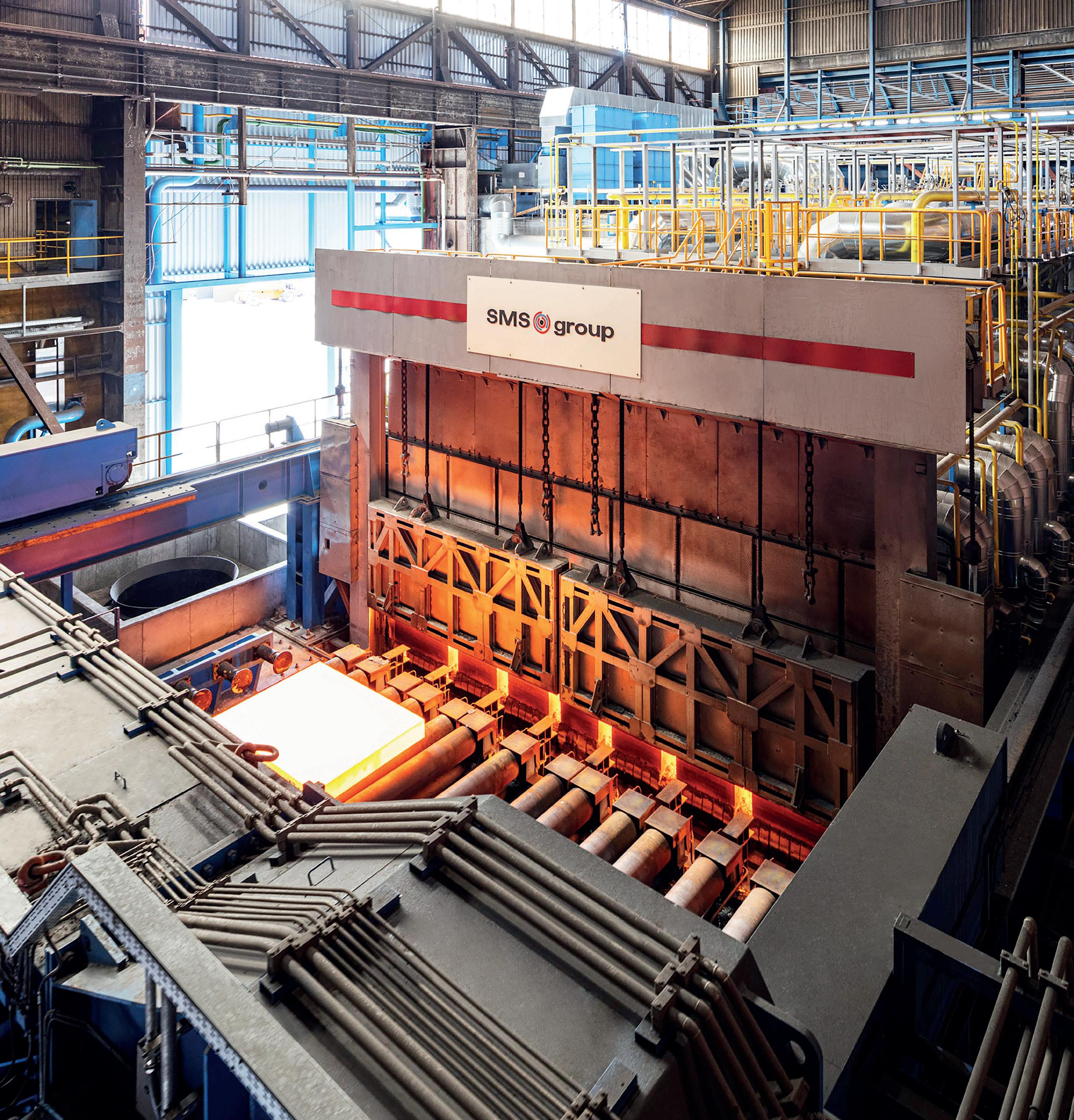
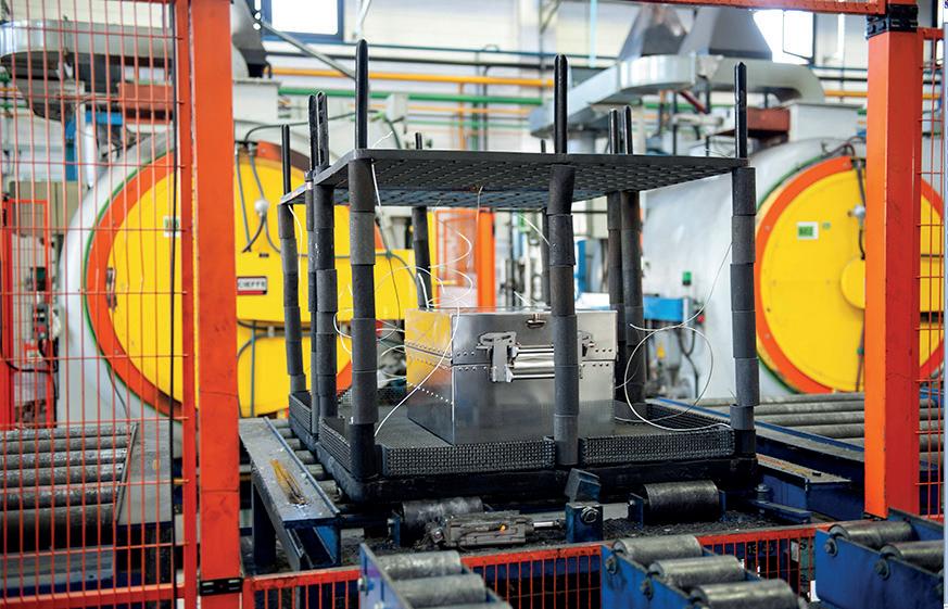
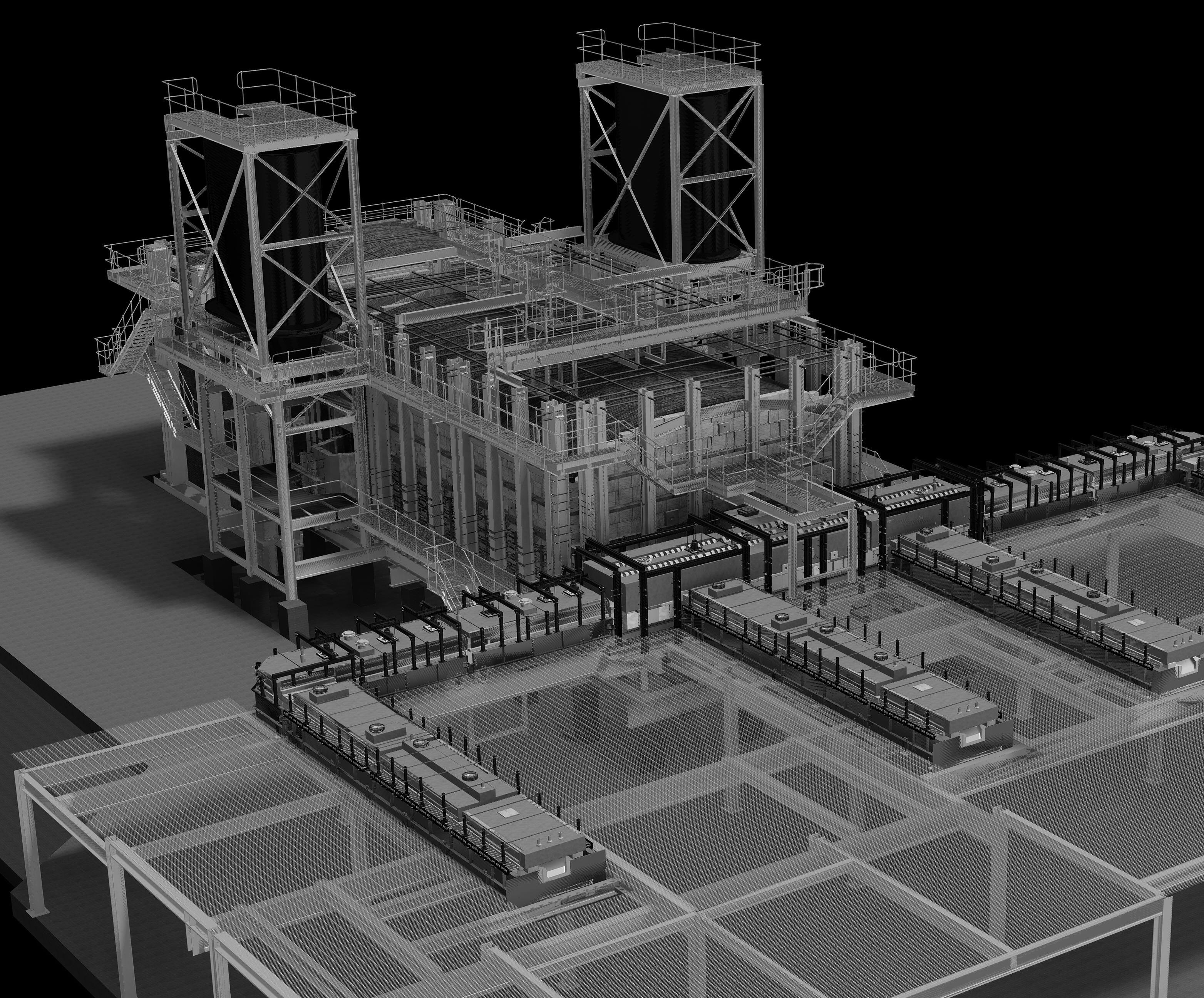
An excellent example of how thru-process monitoring can help optimise the operation of a process is that of the demanding reheat processing of Steel Slabs prior to rolling.
GLOBAL FURNACES 14 Furnaces International March 2023 www.furnaces-international.com
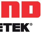
Steel Slab Reheat System
The PhoenixTM ‘thru-process’ temperature profiling system has been designed specifically to allow comprehensive monitoring of the slab/ billet, through the entire furnace pre-heat and soak processes to validate mathematical models used to control the furnace programs.
GLOBAL FURNACES 15 Furnaces International March 2023 www.furnaces-international.com
Optic
The TS07 system allows temperature monitoring both along the slab length and at different core depths within the slab. The water filled phased evaporation thermal barrier provides protection at up to 1300°C, is mounted in a cut-out within the slab allowing heavy duty MI thermocouples to be run along the slab to where measurement is required.
By applying accurate profile data to mathematical models, targeted roughing mill exit temperatures can be set to obtain a desired furnace drop out temperature throughout the product thickness. Accurate control of such variables allows a successful rolling operation with minimal scale build up maximising mill yields, saving significant energy and maximising production throughput. By accurate optimisation and reduction of the furnace operating temperature, the furnace life can be extended. At the same time under temperature products can be prevented, further protecting down-stream processing machinery.
GLOBAL FURNACES 16 Furnaces International March 2023 www.furnaces-international.com
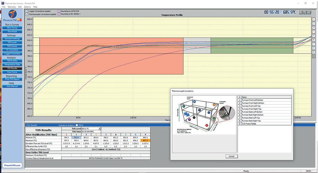
TUS
4. What are the major innovations introduced by PhoenixTM in Temperature profiling?
The following section describes innovations to improve the monitoring of very different heat treating applications.
Oil Quench system
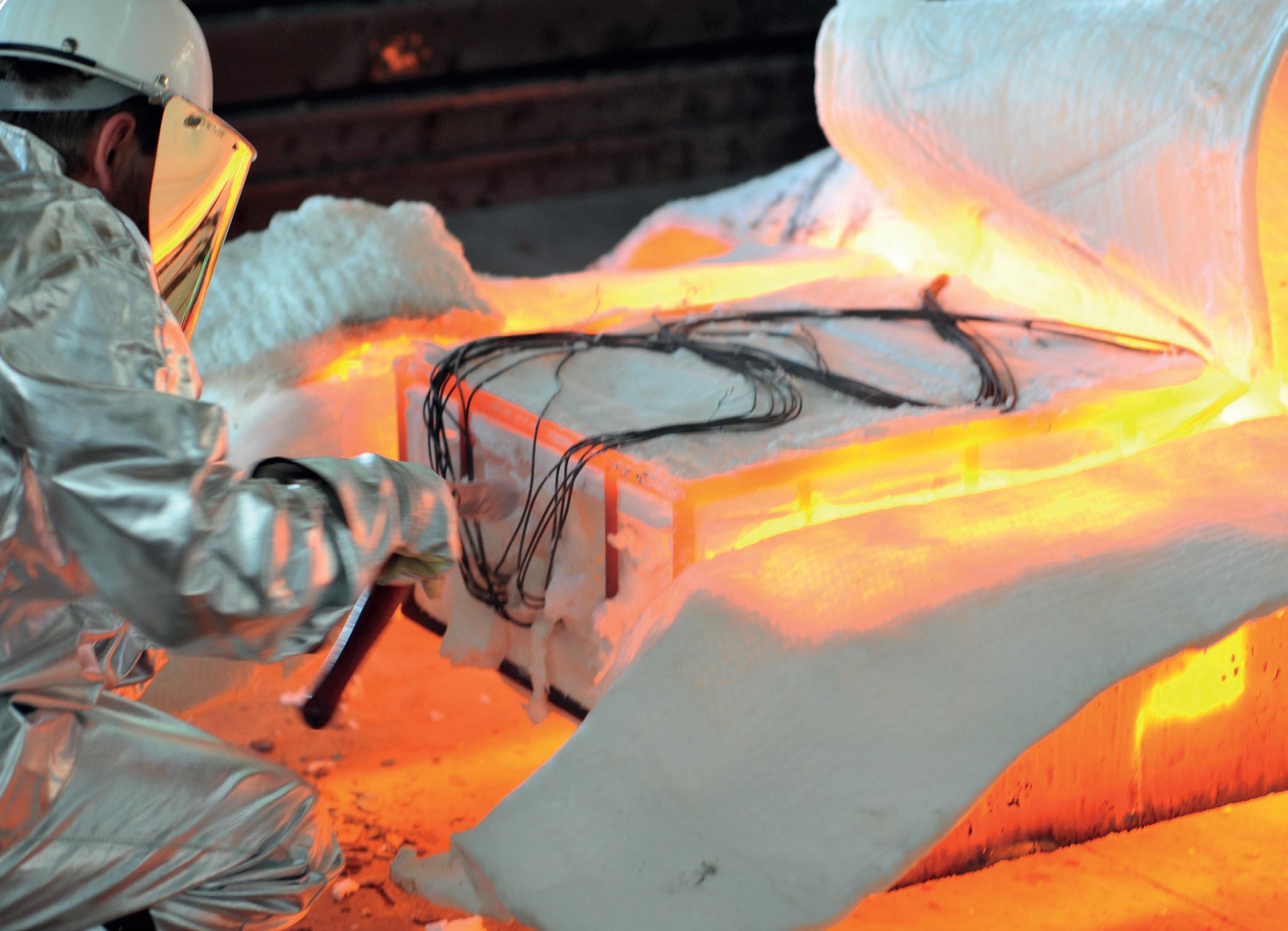
PhoenixTM are proud to have developed the first system, to not only allow monitoring of steel in a sealed gas carburizing furnace, but also allow safe monitoring of the critical integral oil quench and transfer through the final wash. The fully sealed thermal barrier is protected by an outer skin of sacrificial insulation blocks contained within a robust structural frame. Historically the monitoring system would need to bypass the oil quench completely which often created a physical and safety challenge retrieving the monitoring unit from the furnace exit where access may be very limited. Allowing passage through the oil quench allows monitoring of the product quench rate which is critical to not only the metallurgical phase transitions within the steel but identifying potential for part distortion / warpage and quench cracking.
Contamination free Controlled Atmosphere Brazing system
In Controlled Atmosphere Brazing, control of the product temperature is critical to achieve selective melting of the filler alloy
580°C -620°C to allow it to flow and fill the joints between the parent metal substrate without risk of melting the substrate itself.
Critical to the process is surface preparation and removal of any oxide layer with the use of a cleaning flux. The flux used is aggressive and can generate HF gas which is damaging to traditional glass cloth used in the construction of thermal barriers.
GLOBAL FURNACES 17 Furnaces International March 2023 www.furnaces-international.com
To eliminate the damage to barriers, extend operational life expectancy, and minimise process contamination outgassing of air (O2(g)) or moisture, PhoenixTM developed a unique TS08 thermal barrier specifically for the demands of Controlled Atmosphere Brazing.
The barrier design significantly reduces the amount of insulation cloth that is exposed to the aggressive flux. To eliminate outgassing contamination of the furnace environment prior to supply, the insulation block is preheated in a high vacuum and back flushed with nitrogen (N2(g)) to drive out any air trapped in the porous insulation structure. For processes where any air outgassing is a significant contamination risk, it is possible, with specific barrier configurations, for customers to purge the small barrier cavity of any remaining air with a supply of low-pressure Nitrogen (N2(g)).
GLOBAL FURNACES 18 Furnaces International March 2022 www.furnaces-international.com
TUS SW
Intrinsic safety ATEX system
With an ever increasing drive to improve health and safety on the processing floor, many areas are now classified as having an explosion risk, with a designated ATEX zone grading. In such areas instrumentation should be certified as ATEX approved to allow safe operation. To extend monitoring in such areas PhoenixTM complemented its data logger range with the PTM1500 Epsilon-x temperature data logger offering a unique intrinsically safe 10/20 channel profiling system. The PTM1500 data logger is certified against the ATEX European and cMETus USA standards as Group II category for safe operation in gaseous and dust environments (ATEX Zone 2 and 22 respectively).
5. What other areas of process monitoring is PhoenixTM looking to offer?
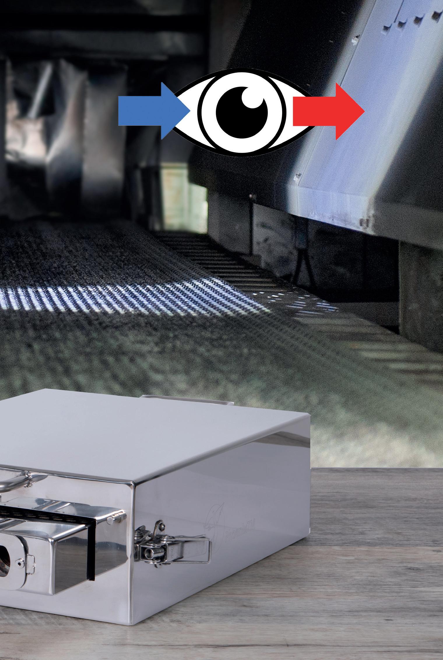
Optical profiling “Optic System”
Optical profiling is a new complementary technique to that of ‘thru-process’ temperature profiling. The new technology developed by PhoenixTM allows for the first-time process engineers to view the inner workings of the furnace under normal production conditions. Travelling through the furnace, with the products being processed, the Optic system gives a product’s eye view of the entire heat treatment journey. Employing similar thermal protection technology ‘thermal barrier’ used in temperature profiling, in place of the temperature data logger a compact video camera and Torch (flashlight) are used to record a video of what a product would see travelling through the furnace. The principle is just like your car’s dash cam, the only difference being that your journey is being performed in a furnace at up to 600 °C. The resulting video “Optical Furnace Profile” shows process engi-
GLOBAL FURNACES 19 Furnaces International March 2022 www.furnaces-international.com
neers so much about how their process is operating without any need to stop, cool and dismantle the furnace. This allows safe routine furnace inspection without any of the problems of costly lost production. The technique allows identification of the true root cause of furnace problems not only effecting the thermal processing of the product but also general furnace operation.
6. What future challenges do you see in temperature monitoring of Industrial heat treating market and how are you addressing them?
Industry is increasingly driven by pressures to comply with quality standards, to which they need accreditation to industry standards such as CQI-9 and AMS2750. Such standards and TUS monitoring requirements are constantly being updated with a need for customers to adapt their monitoring surveying SOPs,
GLOBAL FURNACES 20 Furnaces International March 2023 www.furnaces-international.com
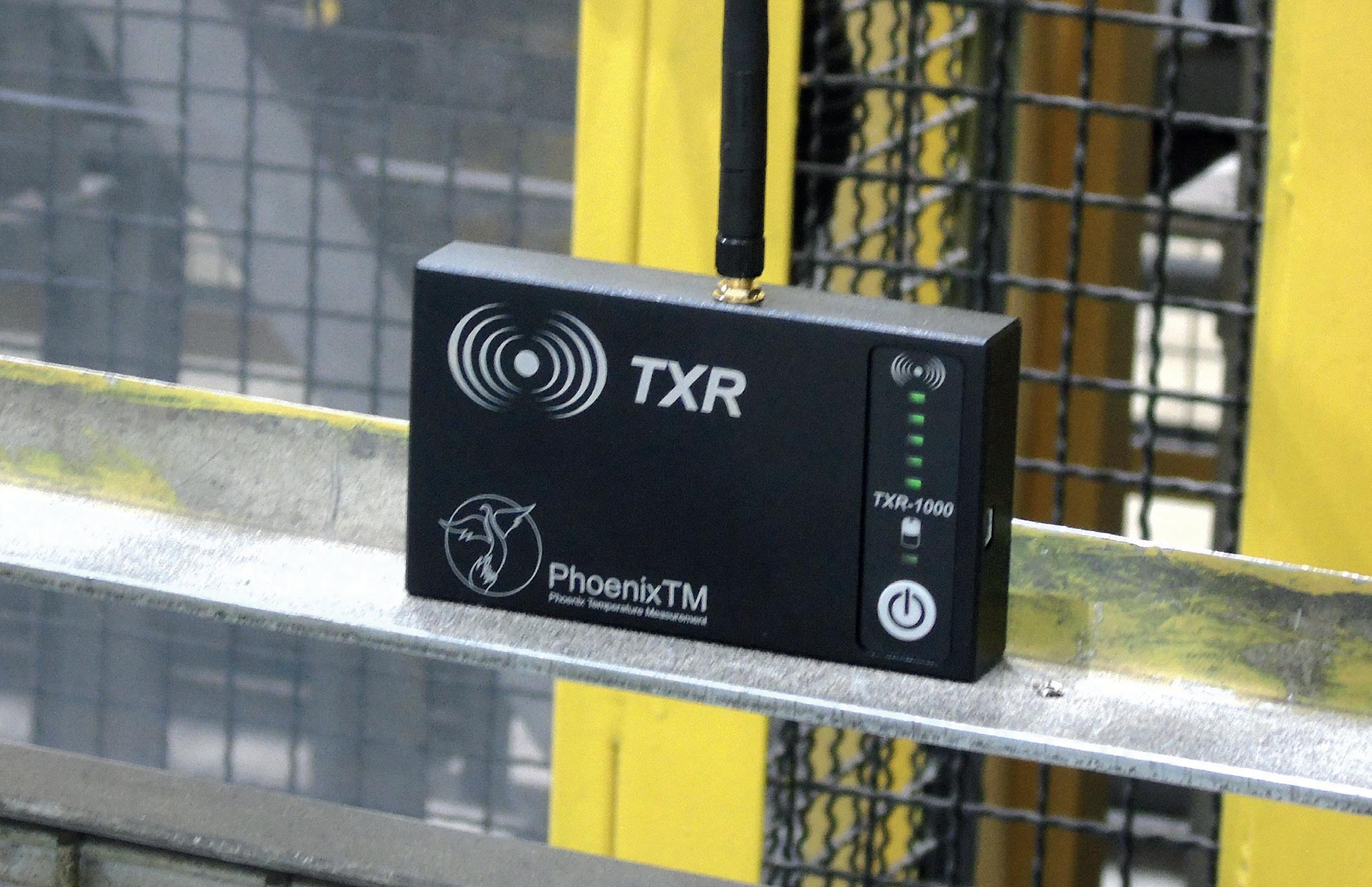
RF
reporting protocols and deliverables.
PhoenixTM works diligently to keep abreast of legislative changes and adapt the system solutions to match the exact requirements of pyrometry standards so that heat treaters can maintain accreditation without extensive inhouse complimentary processing and reporting. As a dynamic team we have the flexibility to address customer requirements whether it be a customised thermal barrier design to match processing criteria or addition of new software features to address new specific analysis or reporting demands.
As a testimony to this fact the following is a direct quote from Safran Landing Systems’ site in Mirabel, Quebec, using the PhoenixTM Thermal View Survey software.
“We can definitely say that by using the PhoenixTM Survey software to produce our TUS has improved the process. Before, we had to debug our VBA code a couple of time per year, not counting the headaches when an up-revision of the AMS2750 occurred. We now have the peace of mind that our TUS are backed by a software from a company which has the right level of expertise and that we will be supported in the future. Also, the ease of use of the software helps a lot.”
We at PhoenixTM are constantly working with customers to specifically adapt the operating software Thermal View particularly Thermal View Survey to comply fully to the demands of the pyrometry standards and allow accurate, quick, efficient and traceable TUS reporting both from a monitoring hardware and data review, calculation and reporting perspective.
In industry automation and a move to real time monitoring and control of processes is becoming a major desire. Although thru-process monitoring is a transient point in time operation,
GLOBAL FURNACES 21
Furnaces International March 2023 www.furnaces-international.com
significant steps have been made to enhance the efficiency and value of the technique. One such innovation is that of RF Telemetry, allowing live monitoring of product temperature during the processing run. Not continuous monitoring but the next step to possible 24/7 product temperature collection. Phoenix TM has a flexible two way system allowing live data transfer from the data logger in the furnace to a monitoring PC, also allowing communication and control of the data logger live in-process.
Portable RF receivers known as repeaters can be positioned/ moved to where they need to be to act as a virtual data chain transferring the RF signal from the data logger back to the monitoring PC with master RF receiver called the Coordinator. No external power supply is needed or cumbersome communication cable between receivers. The receivers can be located exactly where they need to be allowing transfer of temperature data over hundreds of meters. Such operation allows you to identify process problems when they happen allowing possible immediate corrective action , reducing risk of waste and excessive process downtime. �
In memory of David Plester one of the original founders of PhoenixTM.
ABOUT THE AUTHOR:
Dr Steve Offley aka “Dr O” is Product Marketing Manager at PhoenixTM

Joined April 2018
25 years experience in the industrial temperature profiling market Company Website: www.phoenixtm.com
GLOBAL FURNACES 22 Furnaces International March 2023 www.furnaces-international.com


WE ARE USING ALL OUR ENERGY DESIGNING YOUR FURNACE, SO YOU DON'T WASTE YOURS! INNOVATION AS STANDARD ® TOLEDO ENGINEERING / TECOGLAS / ZEDTEC / KTG ENGINEERING / KTG SYSTEMS / EAE TECH www.teco.com
Making the Furnace of the Future
By Zahra Awan*
With thanks to Glassman
Events by Glass International
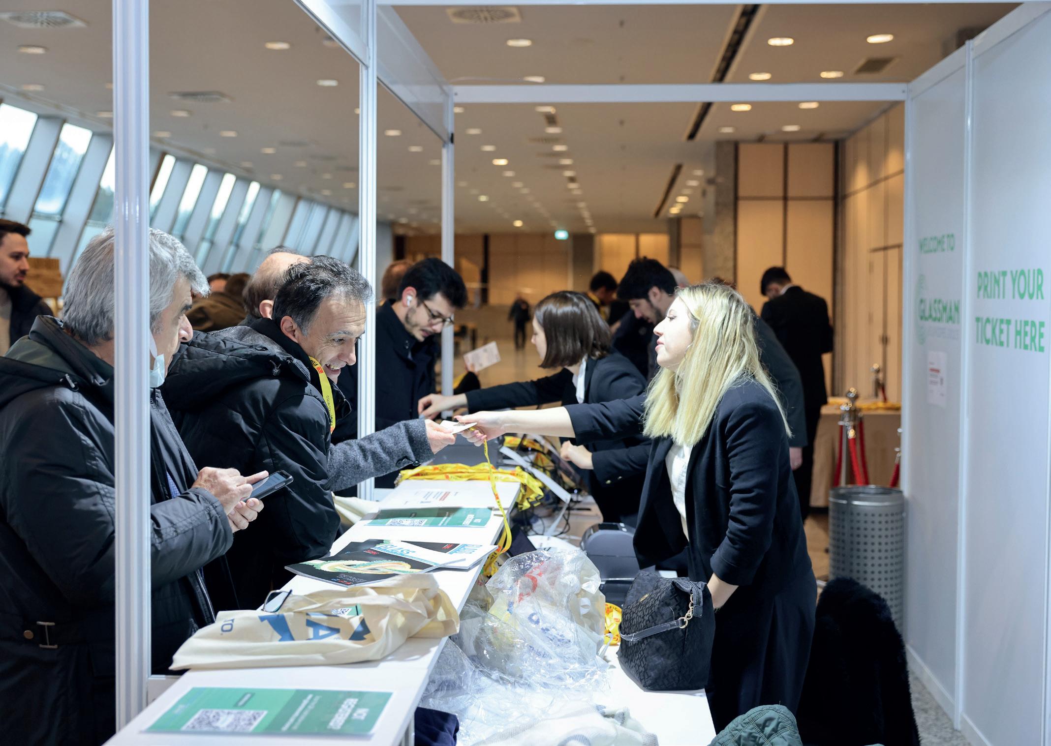
Furnaces International hosted a session on ‘Making the Sustainable Furnace of the Future’ at the Glassman Events Europe event.
 *Editorial Assistant, Furnaces International
On behalf of Quartz Business Media, Furnaces International, and Glass International, we would like to extend our sincerest condolences and best wishes to all those who have been affected by the Turkish earthquakes.
GLOBAL FURNACES 24 Furnaces International March 2023 www.furnaces-international.com
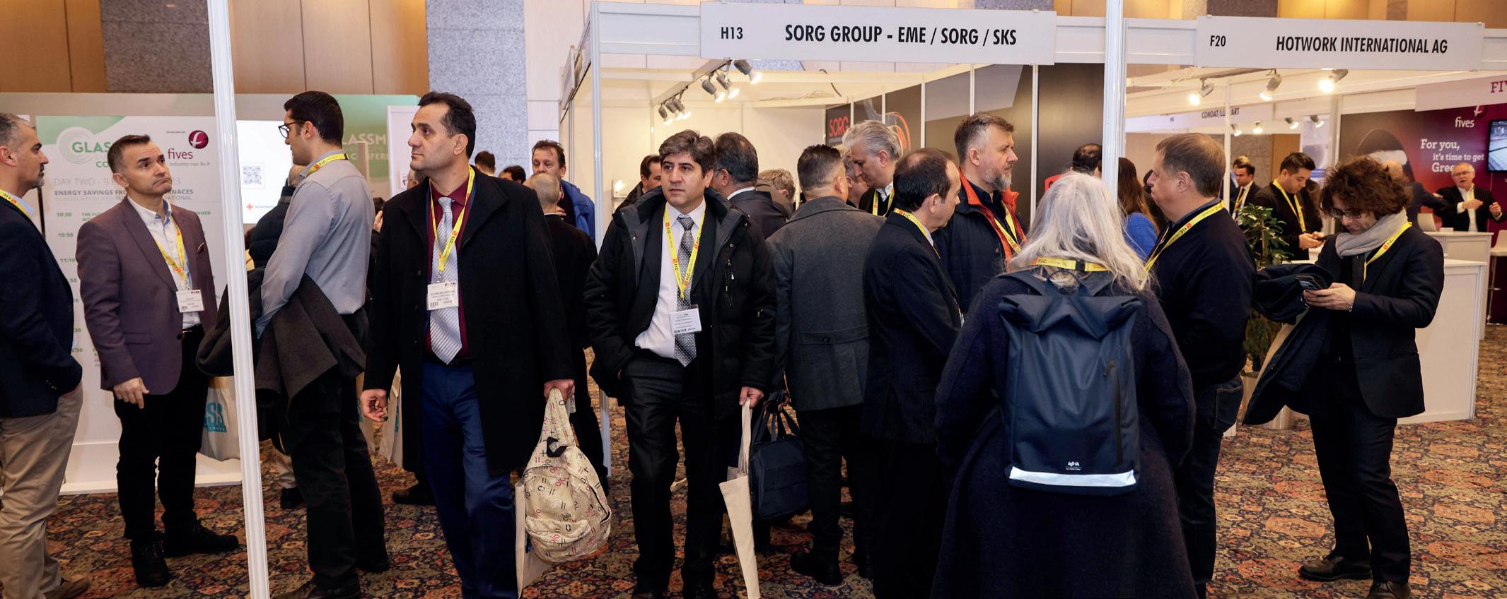
Furnaces and heat treatment is infamously demanding of energy; throughout the session, speakers from across Europe discussed the possible solutions that could tackle the issues faced in the industry. Taking place between the 8th – 9th February 2023 in Istanbul, the Glassman Europe event provided key players with the chance to connect, discuss and learn of the latest developments in the industry.
Following geopolitical tensions, the energy crisis has impacted almost, if not all, heavy industries. On top of this, we are facing the threats of recession with inflation. The push for industries to decarbonise by 2050 is one of our kinder tasks, and one that should be seen as opportunity rather than a challenge.
This being said, the challenge of decarbonising is a greater challenge for the Furnaces Industry, however, without furnaces, there is no glass.
The ‘Making the furnace of the future’ session, co-hosted by
GLOBAL FURNACES 25 Furnaces International March 2023 www.furnaces-international.com
Speaking next on behalf of Furnace International was Phillippe Kerbois, Global Industry Manager – Glass, AMETEK Land. In his presentation, ‘Combining IMAGEPro Glass with NIR-B-2K Thermal imaging to Improve Your Carbon Footprint and Reduce NOx Emissions in Glass Furnace Applications’ he continued on a similar theme to Mr Hakes. Mr Kerbois noted the importance of data collection in the name of technological advancement and development. He has elaborated on his presentation in a follow up editorial which can be read on page ….
Speaking next was Neil Simpson, Consultant and Managing Director, Simpson Combustion Ltd. Further elaborating on the importance of data measurements, his presentation ‘How much CO2 are glass furnaces producing and why you may want to measure?’ began with a short anecdote on “the cost of the analyser [in the 1990s, which] was the same price as a Vauxhall Astra!”. The message that “CO2 measurement [must be a] part of operation and decarbonisation strategy” was grounded from the beginning. Despite the challenges of 2023 namely the Ukrainian crisis, the energy crisis and living crisis (to name a few), the targets for decarbonising the glass furnaces industry by 2050 is still the goal. Claiming that the industry has somewhat regressed from the times where furnaces were fuelled on biofuels, i.e., wood, he notes his hope for biofuels or hybrid furnaces. Closing his presentation, Mr Simpson concluded that “Only when you know where you really are can you plan efficient path for decarbonisation. Only by measuring and recording CO2 will you make operators and stakeholders aware.”
Closing the day and session were CelSian speakers, Andries Habraken, Segment Leader Process Optimisation and Oscar Verheijen, Segment Leader R&D and GlassTrend Chairman. List-
GLOBAL FURNACES 26
Furnaces International March 2023 www.furnaces-international.com
Greg Morris. Editor Glass International
Furnaces International, aimed to target new innovations, challenge opinions and theorise solutions. Below is a summery of the Furnaces International Sessions.
Opening the session was Stuart Hakes, Chief Executive, F.I.C. In his presentation on ‘The Future of Glass Furnaces in a Decarbonised World’, he discussed the dilemmas faced with alternative fuel sources. Optimism in the face of realism only becomes a hindrance; this is highlighted by Mr Hakes. One reality check given by Stuart Hakes was on the positive outlook on biofuels. Usually praised as a carbon neutral alternative to fossil fuels, it is easy to dismiss the reality that it can “take a tree over 40 years to grow, therefore 40 years to replace the fuel we have just taken… can this be considered as sustainable?” Hydrogen and electric alternative fuels were also placed under interrogation as it came to light that the industry simply does not have the knowledge and means for the ideal furnace of the future. Maintaining the trend of ‘realism’, Hakes went onto state “the industry should consider the benefits of investing in a cheaper furnace, designed to last 10 years, in comparison to an expensive furnace that only lasts 20 years [and whose technology is outdated].” As the industry is rapidly changing, technology in 20 years will be vastly outdated. Therefore, a cheaper, short-term investment makes way for a second investment in a more efficient and technologically advanced machine, designed to last long term.
Short Term Solutions
• Boosting share increase
• Improve process efficiency
• Increased use of recycling glass
• Use of alternative raw materials
• Advanced process control (APC)
• Batch and/or cullet preheating
• Heat recovery systems
Mid-Long-Term Solutions
• Fuel switching (hydrogen, biogas)
• New furnace concepts
• Carbon capture technologies
• Alternative glass compositions
GLOBAL FURNACES 27 Furnaces International March 2023 www.furnaces-international.com
ing the mid-long- and short-term CO2 emission strategies, it is apparent that although there are options for the industry, we are restricted in options:
Once again, investing in research and data is the key to progress. The speakers provided us with CeSian’s “Stepwise approach to reduce energy and CO2,” which fell in line with what previous speakers had already noted:
� Evaluate furnaces in the energy benchmark database
� Full on-site energy and CO2 audit
� Generation of energy balance, visualising all energy flows
� Overview of technological options
� Select the best option
� Detailed simulation to analyse the impact of the chosen option(s) on glass quality, furnace lifetime, and emissions
� Final decision on the action(s)
The overall conclusion to the event was the importance of data collection and monitoring of current technology. It is also important to note that the industry is now in a place where investments on technology must be considered in ways that we would not have done so in the past. The benefits of short and long term investments is now its own challenge, with this, we all look forward to seeing how the furnaces industry will develop in 2023. �
GLOBAL FURNACES 28


ST. LOUIS, MISSOURI, USA 800 325 7075 | www.gillespiepowers.com | 314 423 9460 ✓SINGLE CHAMBER / MULTI CHAMBER FURNACES ✓SCRAP DECOATING SYSTEMS ✓TILTING ROTARY MELTING FURNACES ✓SCRAP CHARGING MACHINES ✓LAUNDER SYSTEMS ✓CASTING / HOLDING FURNACES ✓HOMOGENIZING OVENS ✓COOLERS ✓SOW PRE-HEATERS ✓REPAIR & ALTERATIONS
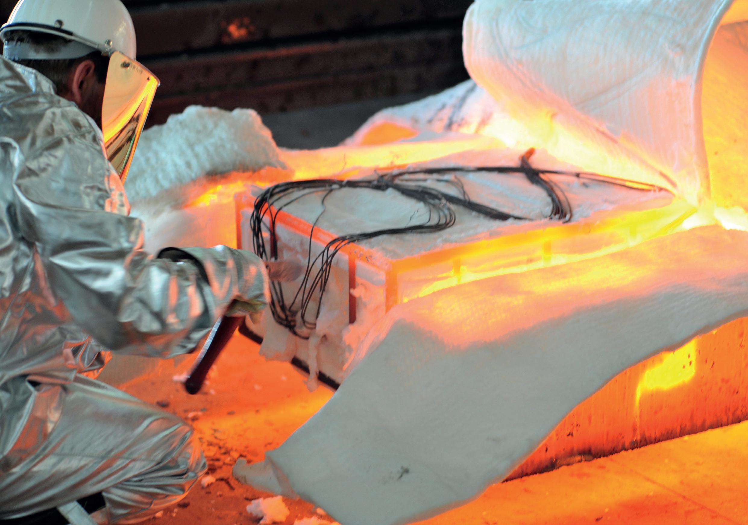
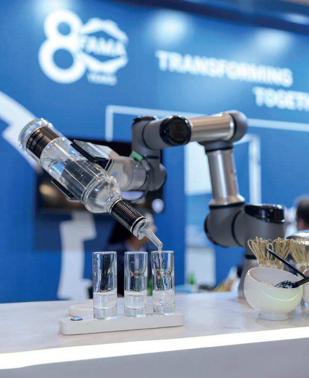
Glass manufacturing is an energy-intensive process. When I first joined AMETEK Land and began promoting high-temperature instruments in 2014, the NIR-B camera in particular, I was always surprised to see the number of furnace operation teams, using TCs and handheld pyrometers, such as Cyclops to build up the thermal profiles and hot spots of glass furnaces. This was the standard for decades, but it was clear to all that a process for optimization needed to be put into place.
In 2016, I started promoting thermal surveys, based on transportable NIR-B. At first, it was to provide a demonstration or just to gauge interest. From this, we were able to ascertain many case studies, which were presented at conferences such as GPC and DGG together with Neil Simpson, of Simpson Combustion and Energy Ltd. The glass market then decided to consider the value of NIR-B as a tool to start decarbonisation which pushed to ensure compliance with air pollution emissions regulations.
Optimising the combustion conditions is essential to minimise energy costs and combining AMETEK Land’s golden four – the NIR-B-2K, IMAGEPro-Glass Software, Cyclops, and our gas analyser, the Lancom 4, became the way to go.


The first requirement for combustion optimisation is to set the correct fuel:air ratio. In general, the requirement is to minimize the amount of excess air whilst still allowing complete combustion of the fuel. This requires a knowledge of the oxygen (O2) and carbon monoxide (CO) concentrations in the flue gases. A high oxygen concentration is an indication that heat is being wasted by venting hot air through the stack, whereas excess carbon monoxide is an indication of incomplete combustion. In most cases, the CO concentration is below 100 ppm but, on furnaces with failing regenerators, CO values more than 70,000ppm
How combining
How combining
2K thermal carbon footprint
2K thermal carbon footprint
Image
By Philippe Kerbois*
GLOBAL FURNACES: GLASSMAN 30 Furnaces International March 2023 www.furnaces-international.com
NIR-B-2K
combining IMAGEPro Glass with NIR-Bimaging and Lancom 4 can improve footprint and reduce emissions
combining IMAGEPro Glass with NIR-Bimaging and Lancom 4 can improve footprint and reduce emissions
* Global Industry Manager
Glass – AMETEK Land
are possible, so wide measurement ranges are essential. The Lancom 4 can accommodate both a low and a high-range CO sensor. Where the CO concentration exceeds the maximum range of the low CO sensor, the sensor is automatically purged with ambient air, and the instrument switches to the high-range sensor.
The next requirement is to minimise emissions of oxides of nitrogen (NOx). There is a direct correlation between peak flame intensity and the formation of NOx. Any parts of a flame that are
GLOBAL FURNACES: GLASSMAN 31 Furnaces International March 2023 www.furnaces-international.com
above 1600 °C will form thermal NOx.
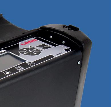
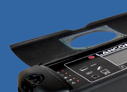
AMETEK Land’s Lancom 4 is a portable flue gas analyser that is integrated into a compact battery-powered unit and can measure up to eight gases simultaneously with nine separate sensors (high and low CO).

Simple to set up and easy to operate, Lancom
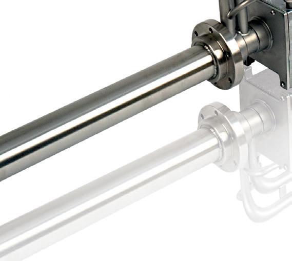
4 enables highly accurate spot and semi-continuous gas testing. It wide variety of applications compliance with safety and emissions requirements. Cus- tomisable to specific gas measurements and process stream conditions, a resilient stainless steel probe extracts the gas sample, while advanced real-time processing techniques produce the highly accurate combustion and emissions calculations needed. A ceramic probe is available for high-temperature applications such as those in the glass industry.
Generally, the higher the temperature, the greater the risk of dissociating oxygen and forming thermal NOx, which is dominant in glass-melting furnaces. While a flue gas analyser such as AMETEK Land’s Lancom 4 can show which exhaust ports have the highest NOx, it may not indicate which of the burners is generating the most NOx.
This is where the use of thermal imaging NIR-B-2K cameras, to see the flames based on fixed locations and reinforced with portable AMETEK Land NIR-B infrared borescope imagers come in handy.
Since the indicated temperatures when the burners are firing are not real, we do not know the emissivity of the flames, but the application of relative isotherms within the image offers the
GLOBAL FURNACES: GLASSMAN 32
Furnaces International March 2023 www.furnaces-international.com
Lancom 4
ability to see which flames are typically hotter and give an indication of the flame length.
Additionally, the NIR-B-2K can support the batch line determination and location (batch coverage function) and build the hot spot locations on thermal profiles.
The tool provides much more value with the new IPV2 software, where ROIs can be measured, and accurate and repeatable measurements of refractories and glass surfaces.
This way, the hottest port can be determined easily when producing the most emissions and particularly NOx.
When working on an oxy-fuel furnace, it is important to consider that at stoichiometric conditions, there is, in theory, 66% water. The reality is that it will be less than this but still a significant potential to literally flood the instrument. When measuring the emissions from an oxy furnace, getting as close to the furnace as possible is key since there can be strange flows in the flue system, specifically when more than one port is used. The benefit of oxy-fuel is that conditions are typically steady state and there is no need to wait for a full firing cycle on a regener ative furnace. The exhaust port is typically under negative pres sure, so you should always seal the probe with fibre to reduce parasitic air ingress.
On an end-fired furnace, the port neck is the best location to test, from an emissions perspective but is likely more difficult from a health and safety perspec tive. The target wall is often used since there is almost always access platforms available. This point is close the potential location of a Lambda or sensor. It is important to remember that an in-situ oxygen sen-
sor measures on a wet basis, because of the sample conditioning, and the oxygen in a Lancom 4 is a percentage on a dry basis.
In conclusion, combining these three technologies, gaining a comprehensive understanding of the glass melting process and make targeted improvements to reduce energy consumption and emissions becomes possible. This can help to improve the sustainability of industrial processes and reduce their impact on the environment. �
GLOBAL FURNACES: GLASSMAN 33 Furnaces International March 2023 www.furnaces-international.com
NIR-Borescope
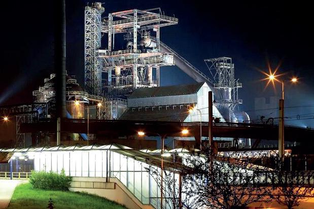
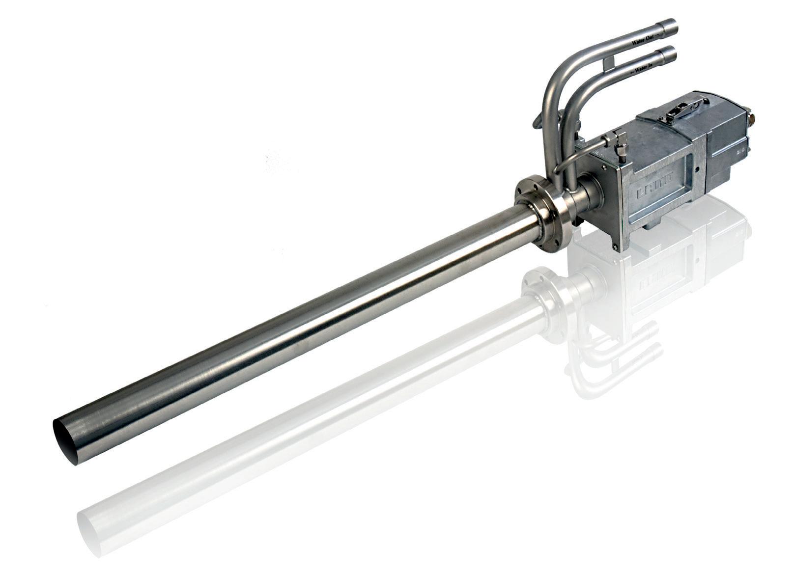
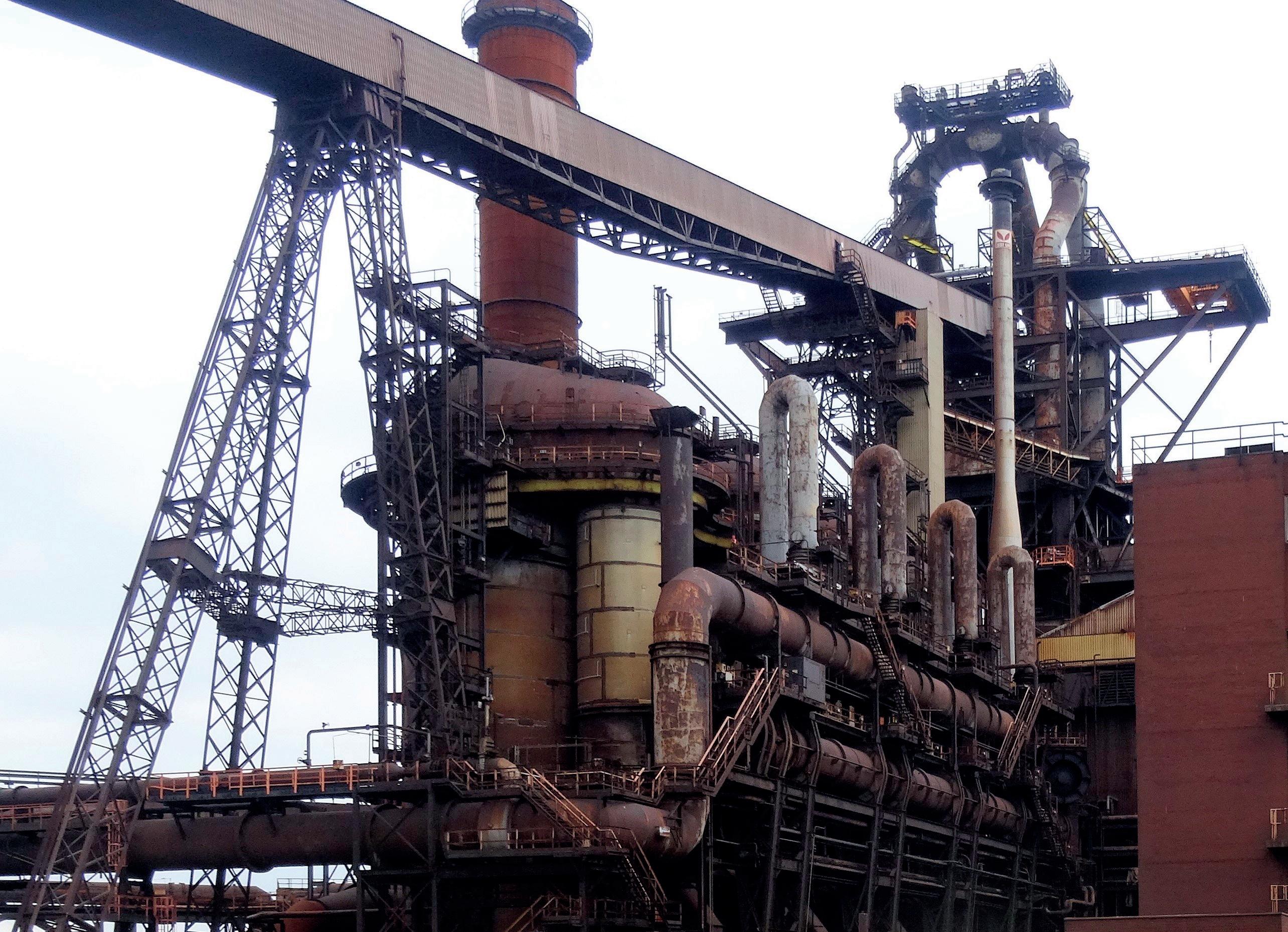
Thyssenkrupp Steel’s Black Giant blast furnace turns 50!
A blast furnace in operation at thyssenkrupp Steel’s Schwelgern steel mill in Germany, turned 50 years old on 6 February.
Known officially as Schwelgern 1 – the Black Giant – the blast furnace is 110 metres in height and has a daily capacity of 10kt of pig iron; it is regarded as one of the biggest blast furnaces in the western world.
Back in February 1973, a team of over 50 chemists and designers worked towards the goal of a ‘blue sky over Hamborn’ – proving that even 50 years ago, the German steel giant was conscious of environmental protection. Since then, of course, there have been massive investments, claims thyssenkrupp Steel, in environmental protection
measures, especially dust removal.
Today thyssenkrupp Steel claims it is well on the way to climate-neutral steel production. Coal-based pig iron production in the blast furnace is being replaced by direct reduction plants which can operate in a climate-friendly way using hydrogen. Eventually, the “black giant” will be retired.
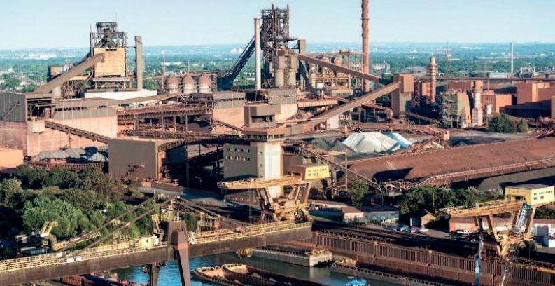
Verallia relights French furnace
Verallia France relit furnace number three at its Chalon-sur-Saône site.
After 49 days of work, furnace number three was relit at the Verallia Group’s ‘most important site’ during a traditional match ceremony.
The furnace, which has been operating continuously since 2016, will be relit for the next seven years.
The oven is dedicated to the production of glass in the ‘dead leaf’ green colour traditionally associated with the wine bottles produced in Burgundy.
During the 49 days of repair, optimisations were made to the furnace improve its performance.
As per Verallia’s tradition, the godmother and godfather had the honour of
NEWS LIFE OF A FURNACE 34 Furnaces International March 2023 www.furnaces-international.com
restarting the oven in the match ceremony.
Godmother of the oven was site employee Myriam Allaoui, and godfather was Guillaume Valdenaire, Purchasing Director of Boisset.
New Tenova EAF for Valbruna ASW Inc.
Italian plant builder Tenova, a Techint company and a prominent force in sustainable solutions for the green transition of the metals industry, recently completed the successful start-up of a new 70t EAF at the Valbruna ASW Inc at a plant in Welland, Ontario, Canada.
Valbruna is a specialty steel producer that manufacturers high quality steel and stainless steel.

Tenova’s latest generation EAF unit has replaced an older EAF. The spout shape of the new furnace, says the company, will provide an increase in melt shop productivity as well as an improvement in production reliability.
The scope of supply included associated auxiliary equipment, the TDRH 4.0 (Tenova Digital Regulator and Harmonics) electrode regulation system, the KT (Koester Technologies) chemical injection system, a ladle-charging material handling system and complete EAF automation.
“It is through our important and long-term relationship with the Valbruna Group that this project was made possible. We have increased the plant’s production, sustainability and safety.”
Aldo Savioli, project manager operations at Tenova Upstream. The KT chemical injection system, says Tenova, is designed to fit the wide range of process needs, balancing energy distribution and increasing the efficiency and
productivity. The automation system is claimed to offer several advantages designed to increase plant efficiency. The system will guarantee the correct execution of the working cycle in relation to the production of different steel grades, while optimizing the parameters and storage of production data. The system is also designed to comply with all safety standards.
“We are proud of the innovative and state-of-the-art EAF design achieved for Valbruna ASW. It is through our important and long-term relationship with the Valbruna Group that this project was made possible. We have increased the plant’s production, sustainability and safety. We expect the plant to become a landmark for the production of high quality steel and stainless steel in the North American market”, said Aldo Savioli, project manager operations at Tenova Upstream.
NEWS LIFE OF A FURNACE 35 Furnaces International March 2023 www.furnaces-international.com
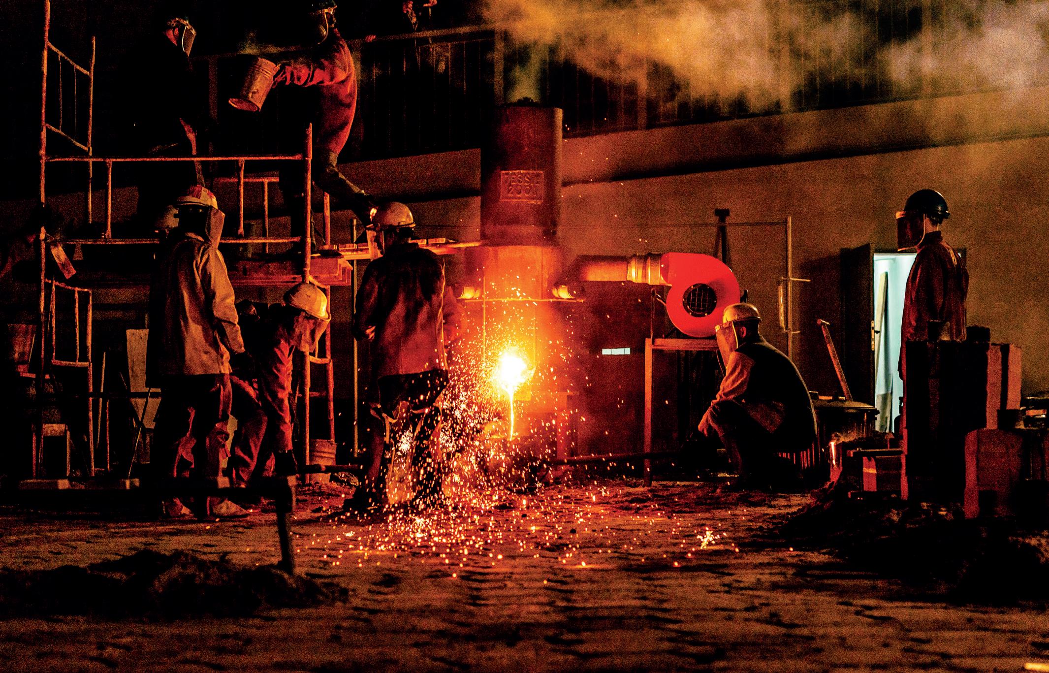
H
EAT REAT
There are many radiant tube options on the market, so which one is best for your furnace and your budget? In this column that compares radiant tubes in carburizing and continuous annealing furnaces, discover how two major types of radiant tubes stack up.
LIFE OF A FURNACE 36 Furnaces International March 2023 www.furnaces-international.com
ODAY
T T
Radiant Tubes: Exploring Your Options
By Marc Glasser*
Introduction
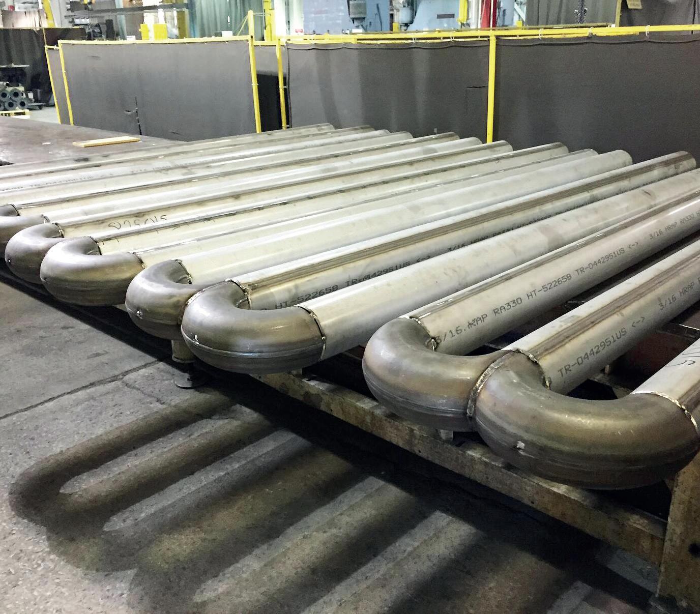
Radiant tubes are used in many types of heat treating furnaces from carburizing furnaces to continuous annealing of steel strip. Generally, a heat treater has three options for radiant tubes: cast tubes, wrought tubes, and ceramic silicon carbide tubes. Silicon carbide tubes are rarely used by heat treaters, so this article will not delve too deeply into this option. Suffice it to say, ceramic materials can often handle much higher temperatures at the expense of ductility; ceramics are more brittle than metals, making them prone to failure from the small impacts, so metal cages are sometimes fabricated to protect them. Most of the tubes being used today are cast radiant tubes. With new casting technology — primarily centrifugal casting — thinner tubes are being cast at a lower cost, which then results in a shorter life.
The primary factors for choosing radiant tube material are tube temperature and carbon potential of the furnace atmosphere. Cost-benefit analysis should also be considered. There are multiple applications for radiant tubes, including carburizing furnaces, continuous annealing furnaces for steel sheet galvanising, steel reheat furnaces, and aluminum heat treating. This article will explore two of the aforementioned radiant tube options, specifically for carburizing and continuous annealing furnaces.
 * Director of Metallurgical Services, Rolled Alloys
LIFE OF A FURNACE 37
Furnaces International March 2023 www.furnaces-international.com
Radiant Tubes for Carburizing Furnaces
Gas carburization is traditionally performed between 1650°F and 1700°F at a carbon potential of 0.8% approximating the eutectoid composition. In today’s competitive environment, more heat treaters are increasing temperatures to 1750°F and pushing carbon potentials as high as 1.6% to get faster diffusion of carbon while spending less time at temperature. INCONEL® HX (66% Ni, 17% Cr) has been a common cast alloy seen in carburizing furnaces. This alloy is regularly selected for its resistance to oxidation and carburization up to 2100°F. Super 22H is more heavily alloyed than HX and is seeing more use as carbon potentials increase but at a premium price. With advances in centrifugal castings, cast tube wall thicknesses have decreased from 3/8-inch to 1/4-inch. Some heat treaters have shared that this decrease in wall thickness has also led to shorter tube life.
Fabricated and welded radiant tubes in alloys 601 and RA 602 CA® have been tested in industry. When tested, these wrought alloys were fabricated to have a wall thickness of 1/8 inch. At the extremes, tubes fabricated from 601 only lasted 50% as long as cast HX. Historically, HX tubes have been approximately 33%
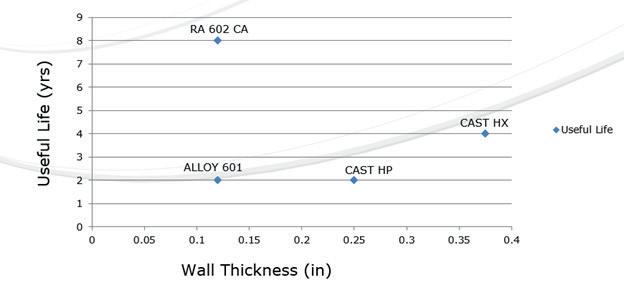
LIFE OF A FURNACE 38 Furnaces International March 2023 www.furnaces-international.com
Figure 1
higher in cost than that of 601 and utilise heavier 3/8-inch walls. A little-known fact is that by switching to a thinner wall cast tube, the life drops by 50%. By switching to 1/8 -wall RA 602 CA, tube life has been extended to eight years or more, while running at 1750°F and up to 1.6% carbon potential, at just a 33% premium over cast HX.
Life cycle data are presented in Figure 1
Radiant Tubes for Continuous Annealing Furnaces
In the area of continuous annealing, the cast alloy of choice is HP/HT (35% Ni, 17% Cr, 1.7% Si, 0.5% C). Here again, this casting has been compared to 601 and RA 602 CA, with the same results. The total life data from these trials are also incorporated into Figure 1. During the collection of this data, there has been no effort to measure the actual tube temperature, so the effect of tube temperature is not clearly defined. In these continuous annealing furnaces, it has been reported that the tubes at the entry end are subject to more heat absorption as burners are firing more due to the continuous introduction of cold material; but in trials, the operators have not kept adequate documentation of specific tubes, making justification more difficult.
Justification for the higher cost wrought alloy needs to take into consideration initial fabricated tube cost, actual tube life, AND the lost production of each anticipated downtime cycle as these downtime costs are often much more than material costs. Only individual fabricators can determine these costs.

LIFE OF A FURNACE 39 Furnaces International March 2023 www.furnaces-international.com
LIFE OF A FURNACE 40 Furnaces International March 2023 www.furnaces-international.com
“
Cost-benefit analysis should also be considered.”
The Economics
Table 1 shows the economics of metal alloy choice. To properly interpret, understand that the costs are not actual, but rather relative to 601, so a round number of 1000 was used. With a 30% greater cost of cast tubes, that translates to a relative cost of $1300. The annual cost is the amortised cost over the life of the tube. The total eight-year cost is the relative cost times the number of tubes that would have to be purchased to obtain the life cycle of one tube of the longest-lasting material over its full life cycle.
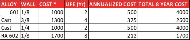
Missing in this analysis is the additional cost of downtime and lost production. For the replacement of radiant tubes in a carburizing furnace, this typically entails a full week to turn a furnace off, allow it to cool, replace the tubes, and then heat it up again. Many heat treaters do not consider this, and therefore it is a hidden cost. Even without the downtime being considered, by examining the total cost of materials (including replacements) compared to the longest-lasting tube, it turns out that the most expensive tube is the cheapest tube. The obstacle to overcome is whether the heat treater is willing to wait eight years to realise these cost savings.
There can be additional factors to consider. With improvements in the efficiency of casting, the actual costs of the thinner wall casting may be somewhat less, but to match the overall cost of the longest-life material, it would have to be less than half the
LIFE OF A FURNACE 41 Furnaces International March 2023 www.furnaces-international.com
Table 1
expected cost. As better, more expensive cast alloys become accepted and actual life data becomes available, these more costly alloys can be added to this table for comparative analysis, too. This same method of analysis can be applied to radiant tubes for continuous annealing furnaces, but more details will need to be added including furnace position. Different alloy candidates will have to be put to the test in actual operations, carefully document what alloy is in what position or location, and when it gets changed out. This becomes quite cumbersome when annealing furnaces (depending on design and manufacture) can have over 200 radiant tubes.
Conclusion
Currently, cast alloy tubes dominate the market. The concept of total life cycle cost has been introduced as a means of more accurately justifying one’s choice of radiant tube. This comes into play more as processes are pushed beyond traditional process conditions. Cost-benefit analysis must be balanced over acceptable amortisation time, of course. However, performing the full analysis as well as the costs saved from downtime may lead some heat treaters to some alternate materials. �
ABOUT THE AUTHOR:
Marc Glasser is the director of Metallurgical Services at Rolled Alloys and is an expert in process metallurgy, heat treatment, materials of construction, and materials science and testing.
Marc received his bachelor’s degree in materials engineering from Rensselaer Polytechnic Institute and a Master of Science in material science from Polytechnic University, now known as the NYU School of Engineering.
For more information: Contact mglasser@rolledalloys.com.
LIFE OF A FURNACE 42 Furnaces International March 2023 www.furnaces-international.com


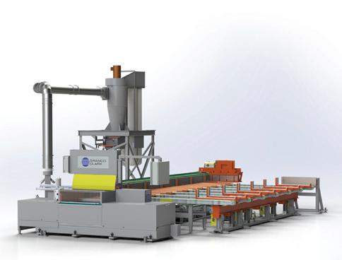

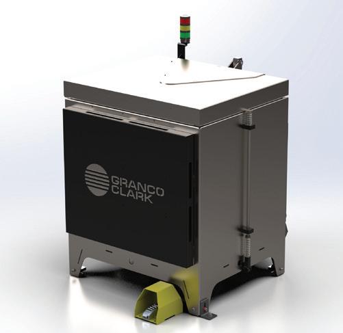
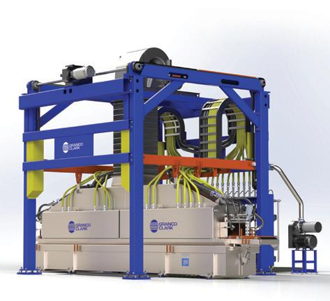
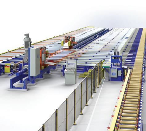
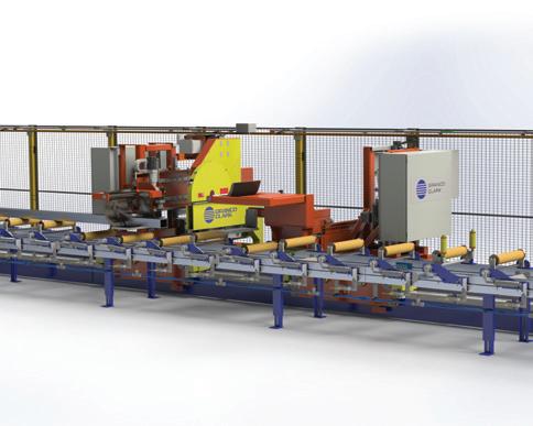


Scan: Impact quench data Engineering. Manufacturing. Global Support. Excellence is our standard. Precision Saw System The industries most productive offline-saw Infrared Die Oven Heat the die, not the air High Impact Spray Quench The leading profile quench in the industry Profile Handling System Fully automatic profile handling system Flying
The industries best
system Hot-Jet
Furnace The industries most energy efficient, flameimpingement log/billet furnace Performance Driven We engineer and manufacture high-performance heating, handling, and quenching systems. We service and support the globe. Contact us to discuss your next project. +1-800-918-2600 | gcinfo@grancoclark.com We are 100% employee-owned www.grancoclark.com
Cut Double Puller
puller
Log/Billet
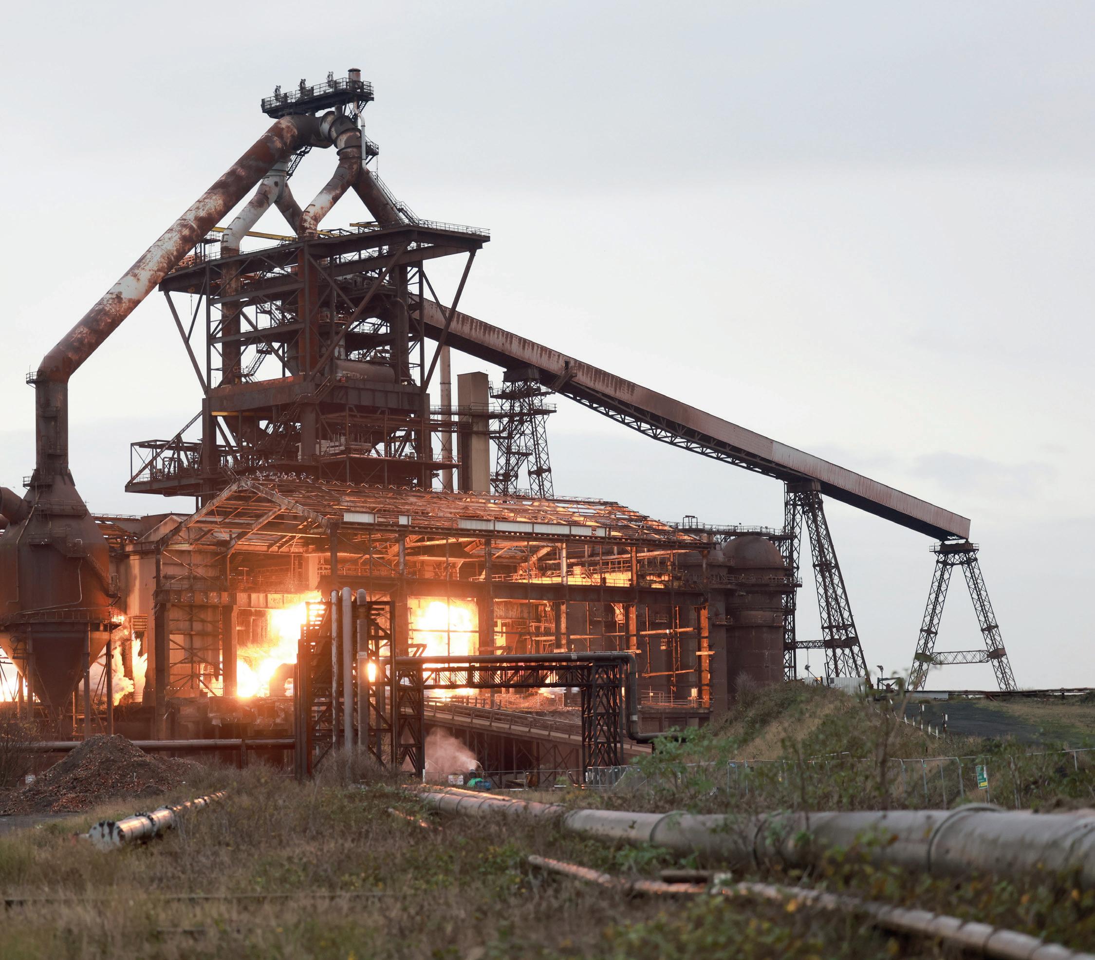
The rise and fall of a blast furnace
Tim Smith* chronicles the history of an iconic UK landmark, Redcar furnace, which after close to five decades of service, was demolished in late 2022.
AT 9am, local time, on Wednesday 23 November 2022, the most significant destruction of the iron industry of Teesside, Middlesborough, North Yorkshire, UK, took place with the demolition of the Redcar blast furnace. Demolition specialists, Thompsons of Prudhoe based in Northumberland, UK, used 175 tonnes of explosives to bring down the largest blast furnace in the British Isles and once, the second largest in Europe. The BOS shop had already been demolished by them in October along with much of the former works infrastructure to make way for a £113m regeneration of the 600 acre (243 hectare) site, at the mouth of the River Tees, as a ‘Freeport’.
The blast furnace was commissioned in 1979 under the ownership of the then nationalised British Steel Corporation as part of a £400m investment, with a further £100m to upgrade the nearby Lackenby steelmaking complex.
The new blast furnace had a design capacity of 10kt/day (3.25Mt/yr) and, at the time, was planned as one of two identical furnaces to be built on the site to accommodate an annual output close to 6.5Mt. In the event, the second furnace was never built.

Open hearth furnaces
Furnaces were first built at Redcar in 1874 by Robson, Maynard
*Consulting editor, Steel Times International and a member of the Historical Metallurgy Society
LIFE OF A FURNACE 44
Furnaces International March 2023 www.furnaces-international.com
& Co which become Walker, Maynard & Co nine years later when four furnaces were in blast. Dorman Long & Co Ltd took over the site in 1915 when assets included two furnaces in operation and an ironstone mine at nearby Kilton. Dorman Long had earned a reputation for bridge building, ship plate manufacture and steel construction activities, at home and abroad. Steelmaking was by basic open hearth furnaces. In 1929, they acquired the one-time world’s largest ironworks, Bolckow-Vaughan & Co, which itself had taken over the Clay Lane ironworks at Eston, Redcar in 1900. The number of furnaces peaked at 40 in 1929 but had fallen to just two by 1957, both located at the Clay Lane works. In 1958, Dorman Long commissioned a Universal Beam
LIFE OF A FURNACE 45 Furnaces International March 2023 www.furnaces-international.com
The moment of demolition the Redcar blast furnace was demolished Picture courtesy Teesside Live Reach PLC)
mill 4km to the south-west of Redcar at Lackenby.
In 1967, the company became part of British Steel and Tube Ltd – a consortium including the steelmakers, Stewarts and Lloyd’s at Corby, Northants, and South Durham Steel & Iron, Middlesbrough. However, this merger was short lived as the UK government nationalised the UK’s steel industry in July of that year, with the works becoming part of British Steel Northern and Tubes Group.
In 1974, under the management of the British Steel Corporation, plans were put into action to build a new modern iron and steel plant at South Gare, Redcar which saw the opening of Britain’s largest ironmaking complex on 12 October 1979; the furnace being lit with fire from Clay Lane’s BF No 1.
In 1988, Britain’s iron and steel industry was once again privatised, and the Teesside complex became part of privatised British Steel. In 1999, British Steel merged with Dutch steelmaker, Koninklijke Hoogovens to form the Corus Group. Corus was sold to Tata Steel of India in 2007 but retained the Corus name and logo on Teesside until September 2010. With sufficient steel capacity supplied by Port Talbot and Scunthorpe works, the Redcar complex sought to supply steel to external customers. However, a 10-year agreement with Marcegaglia of Italy ended prematurely and, with no alternative demand, the furnace was blown out in December 2009 and mothballed. A short reprieve occurred in 2011 when the Thai Steel company, Sahaviriya Steel Industries (SSI) bought the iron and steel works to supply slab to its rolling mill in Thailand. Modernisation of the furnace was completed and it was re-lit in April 2012. In 2015 SSI UK went into liquidation and the furnace was blown out once again, never to be reprieved.
LIFE OF A FURNACE 46 Furnaces International March 2023 www.furnaces-international.com
The Redcar 14m hearth diameter blast furnace had a working volume of 4246m3 a PCI rate of 240kg/t and reached an output of 11kt/day of iron
(Picture copyright J Aylen)
A heritage task force was established to document the 170year history of iron and steel on Teesside with the aim of recording the cultural and economic industrial heritage of the area. From a public response of just 200 people, of which only one third commented on the blast furnace, just over half called for its demolition. Consequently, the task force recommendation was not to preserve the furnace as a public attraction but rather to retain various artifacts from it to be put on display near the entrance to the site and also to enhance existing nearby industrial heritage resources including the ‘Steel Stories’ exhibition at Kirkleatham Museum, Teesside Archives British Steel Collection and the Cleveland Ironstone Mining Museum in Skinningrove, which has undergone capital development.
LIFE OF A FURNACE 47 Furnaces International March 2023 www.furnaces-international.com
They did recommend considering preservation of the Dorman Long Tower, originally a coal bunker, and finding a new use for it. However, this was demolished in September 2021.
Lack of preservation
Sadly the destruction of the UK’s 20th century heritage is all too common and contrasts with that found elsewhere. Only the Magna Science Adventure Centre in Rotherham, the former Templeborough open hearth steel shop, later converted to electric arc steelmaking, has been preserved. Here, one of the electric arc furnaces has been retained, its light and sound reproduced periodically.
In Europe, the European Route of Industrial Heritage (ERIH) lists numerous preserved sites country by country. If one selects the ‘Iron & Steel’ filter details of iron related sites, including those with preserved furnaces, are revealed: https://www.erih.net/. Germany is particularly rich in sites including one of two blast furnaces at Neunkirchen decommissioned in 1982. This was the first blast furnace worldwide to be actively refurbished for the purpose of opening to the public. More recently, BF No 5 of Thyssen Krupp, Duisburg has been preserved in-situ within what is now the Duisburg Landscape Park. Further afield, we have the Carrie Furnaces in Homestead, Pennsylvania USA (decommissioned in 1978) open for special occasions and in Japan, the Yahata Steel Works in Yahatahigashi-ku, Kitakyushu, decommissioned in 1972.
Future of the site
In addition to becoming the UK’s largest Freeport, the site is already earmarked for the Net Zero Teesside Power carbon
LIFE OF A FURNACE 48 Furnaces International March 2023 www.furnaces-international.com
capture, utilisation and storage, power plant, and GE Renewable
Energy’s mammoth wind turbine blade manufacturing facility. Development of the site will be Europe’s largest brownfield undertaking, planned to create 18,000 jobs over the next five years. � On the internet
1) Demolition videos
https://news.sky.com/video/teessides-iconic-redcar-steelworks-blast-furnace-demolished-12754292
(Source: Sky News)
https://www.youtube.com/watch?v=_mmxJtvStWo
(Source: Thompsons of Prudhoe)
https://www.youtube.com/watch?v=8zZ02VSwyc8
(Source: Fat Egg Media)
2) Teesworks Heritage Task Force
https://www.teesworks.co.uk/about/teesworks-heritage-task-force
3) Kirkleatham Museum Steel Stories
https://redcarcleveland.co.uk/enjoy/steel-stories-2/
4) Cleveland Ironstone Mining Museum
https://landofiron.org.uk/
5) Teesside Archives British Steel Collection
https://teessidearchives.wordpress.com/tag/british-steel/
LIFE OF A FURNACE 49 Furnaces International March 2023 www.furnaces-international.com
AGC and Saint-Gobain partner for decarbonised
Borosil Renewables starts third solar glass production
India’s Borosil Renewables has started trial production of its third solar glass furnace, which has increased its capacity in India to 1,000 tons per day.
This is the equivalent to 6GW solar module production a year.
The company’s other two furnaces in India have production capacities of 240 tons per day and 210 tons per day.
The manufacturer now has a total solar glass capacity of 1,300 tons per day in India and Germany.
Its capacity includes includes 300 tons per day in Germany after it acquired Europe’s largest solar glass manufacturer, Interfloat Group.
NEWS GREENER FURNACES 50 Furnaces International March 2023 www.furnaces-international.com
decarbonised flat glass line
AGC and Saint-Gobain will collaborate on the design of a pilot flat glass line that is expected to reduce the companies’ direct CO2 emissions. AGC’s patterned glass production line in Barevka, Czech Republic, will be entirely refurbished into a high performing and modernised line. The line aims to be 50% electrified and 50% fired by a combination of oxygen and gas.
This is a technical breakthrough compared to current technology used in flat glass furnaces fired by natural gas.

It will be the most sustainable flat glass line design contributing to both companies’ paths towards carbon neutrality and to the necessary acceleration of the flat glass industry decarbonisation.
This development could pave the way for the conversion of industrial flat glass lines that are mainly powered by low carbon electricity, more efficient than any gas solution, and have reduced carbon emissions for the customers’ benefit.
The technology is expected to be implemented on the patterned glass line for operational success by the second half of 2024.
Davide Cappellino, President Architectural Glass Europe & Americas of AGC, said: “This hybrid design melter is another important milestone in our Net Zero Trajectory to become carbon neutral as a company by 2050.
“The breakthrough design will be done jointly with Saint-Gobain, combining the best technology knowledge of both companies.”
Joana Arreguy, Industrial Director Glass, Saint-Gobain, said: “We are delighted to co-develop with AGC [the] new, most advanced technology for flat glass production in the world.”
The news comes a few months after Saint-Gobain became the first company in the world to achieve zero carbon production of flat glass last May.
NEWS GREENER FURNACES 51 Furnaces International March 2023 www.furnaces-international.com
production furnace
Glass Futures: sustainable fuels could reduce glassmaking carbon emissions by 80%
While the results of less commercially available and technically unproven options like biofuels and hydrogen were positive, the report concludes that options to decarbonise the industry won’t be restricted to one single solution due to geographic drivers such as localised hydrogen networks and electrical grid capacity.
It found that no single low-carbon route will be suitable for the 21 largest glass manufacturing sites in the UK.
A report suggests sustainable fuels in the use of glass manufacturing could reduce carbon emissions by up to 80%
UK research organisation Glass Futures published its report for the Department of Business, Energy and Industrial Strategy (BEIS) which answers some of the fundamental questions surrounding low carbon fuels within the UK glass industry, with learnings applicable to the global industry.
Glass Futures is building a £54 million 165,000ft2 Global Centre of Glass Excellence in St Helens, UK. It is due for completion in 2023 to pioneer research into decarbonising glass and other industries, has established:
Biofuels: The use of 100% liquid sustainable biofuels resulted in carbon savings of between 70-80% when compared with high carbon natural gas.
Hydrogen: The potential for replacing natural gas with hydrogen has been demonstrated on an industrial scale and appears promising but the solution varied across the different sub sectors (float, container, etc). Further research is required to understand the effects of hydrogen combustion on glass melting and forming processes, glass quality, Nitrogen Oxide (NOx) emissions and refractory corrosion.
Electric melting: Some manufacturers are using increasing amounts of electric ‘boost’, with electricity supplying around 20-40% of melting energy. Increasing beyond this amount of boost requires significant changes to furnace design and other barriers exist including uncertainty around the rising cost of energy.
Economic modelling: Alongside a series of pilot scale tests, economic modelling and research into hybrid solutions from present day to 2100 found that payback on net zero investment is possible by 2060, based on retrofitting solutions and given a positive policy framework co-created by industry and government.
Dr Palma González García, Combustion Technical Lead at Glass Futures said: “Our research indicates that future investigation is warranted and that options to decarbonise the glass industry won’t be restricted to a single solution... A complex landscape exists around the many fuel switching solutions, and a number of key technical questions still remain regarding the long-term impacts of fuel switching choices.”
She added: “It’s clear there must be additional research to de-risk alternative technologies to enable the transition required.”
The BEIS IFS project has attracted critical global acclaim and it’s hoped the outputs of the report will provide a platform for discussions by policymakers as a blueprint to enable the uptake of key fuel switching options.
NEWS GREENER FURNACES 52 Furnaces International March 2023 www.furnaces-international.com
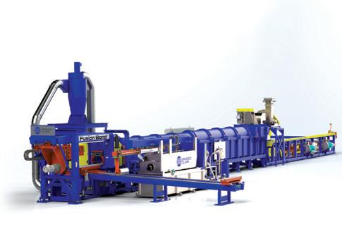
THE HYDROGEN HYBRID SOLUTION
Safe. Flexible. Clean. Efficient. Plug’n’play. What else? A European loyal customer has been the first to trust into our eco-breathly solution for a new mill project to be installed in 2023.
Do you wanna be the next partner adopting SMSZEROFLAMEHY2 solution?

We continue on our pathway of innovation for delivering excellent performances to our customers for the years to come! We start to breathe again.
Our expertise covers:


> From 100% natural gas to 100% hydrogen H2

> Down to 40 ppm @ 3% O2 NOx emissions.
> Up to +5% emissivity compared to a traditional natural gas burner.

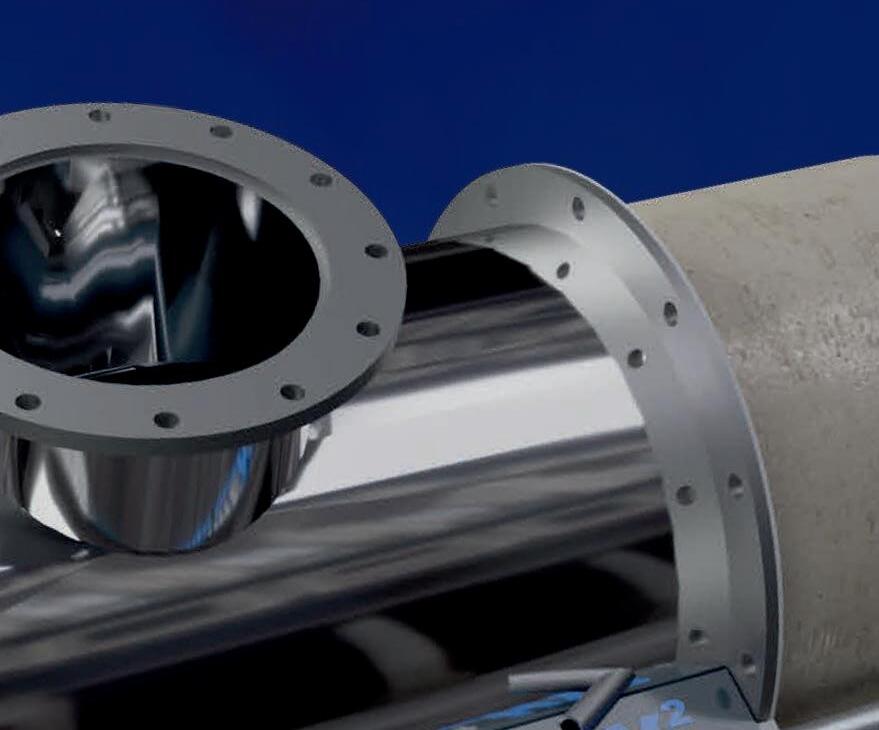

> Substantial CO2 reduction compared to a traditional natural gas burner.
> From 500 kW to 3,500 kW power size availability.
> Overboost mode (extra power in quasi-flameless combustion).
www.sms-group.com
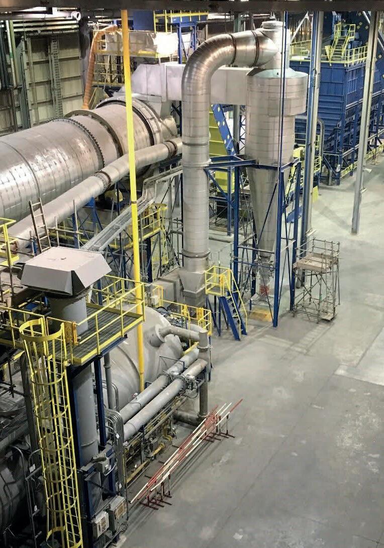
GREENER FURNACE 54 Furnaces International March 2023 www.furnaces-international.com Decarbonising
Ernesto Cattaneo* and Annick Lachance Nyiringango** investigate how operating conditions affect the amount of CO2 emitted by a regenerative glass furnace, while observing operating costs.
*Head of Innovation Department,
**R&D engineer for SGRPRO, a Stara Glass affiliate, Stara Glass, Genova, Italy

https://www.staraglass.it/
Decarbonising regenerative glass furnaces
The glass industry contributes significantly to CO2 emissions - 5% of European production according to European Union Emissions Trading System (EU ETS). Therefore, the industry is committed to participating in the global initiative to reduce them.
ecarbonising Furnaces
CO2 emissions during glass production originate from two sources and only a small portion comes from batch chemical reactions. The remainder, easily more than 80%, is caused by fossil fuels. They are burned to heat furnaces, due to the high temperatures
GREENER FURNACE
Furnaces International March 2023 www.furnaces-international.com 55
D
required to melt the raw materials used to make glass.
Though, in the process of designing a glass furnace, there are many unchangeable boundaries set by production needs which deeply affect the furnace performance, the designer has few but powerful operative leverages.
Several years ago, Stara Glass published an article describing how the process parameters impact the furnace consumption. In the light of the decarbonisation movement, we propose a similar evaluation, focused on the CO2 emission.
In this article, we will explore the influence of operating parameters on the CO2 emissions, consumption, and operating costs. The parameters will be measured through FurnaceMaster, a software designed by Stara Glass. It allows the designer to precisely define all computing input and collect all the significant output.
GREENER FURNACE 56
Furnaces International March 2023 www.furnaces-international.com
Input
Parameter Driver Notes
Pull [t/day] Set by the glassmaker based on production needs. The more stable it is, the more efficient the furnace will be.
O2 excess at the port [%] Environment, materials, consumption, and quality. It is used for balancing undesired productions of CO and NOx.
Boosting [kW] Investment
It is always useful for quality and capacity but it also increases the production cost
Cullet % Production and colour. Remarkably impacts consumption.
Mix humidity % Production, geographical position, storage method. Remarkably impacts consumption.
Preheated air temperature [°C] Available space / design The higher, the better.
Output
Parameter Notes
CO2 Emission [Ton/Year] It increases with energy consumption.
Gas consumption [Sm3] It increases with the pull.
Specific consumption [kcal/kg] It decreases when the pull increases and with the usage of electrical power.
Production cost [€] It decreases with a larger utilisation of electrical boosting.
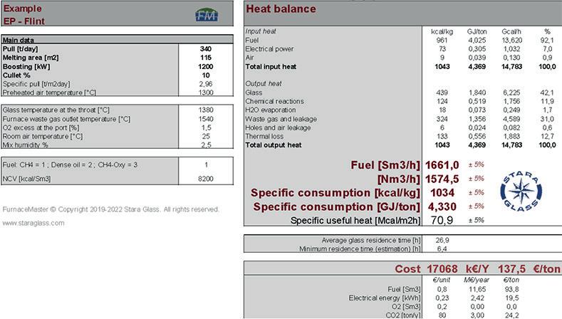
Assumptions
For our study, the following consumption costs are assumed:
Fuel cost [€/Sm3] 0.8 Electric energy cost [€/kWh] 0.23 CO2 [€/ton] 80 GREENER FURNACE 57 Furnaces International March 2023 www.furnaces-international.com
Figure 1. Inputted nominal data in FurnaceMaster from a regenerative furnace producing container glass.
Table 1
Table 2
Nominal data
Figure 1 shows inputted nominal data in FurnaceMaster, given a state-of-the-art regenerative furnace producing container glass. Since the glass is white, the cullet is considered to be 10 to 60%.
Studied Parameters
The parameters below (table 1) will be individually varied in the analysis; their impact on CO2 emissions will be evaluated. We will also look at the fuel consumption, specific consumption, and production cost in table 2
Results
Pull
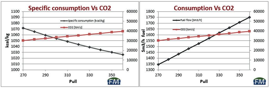
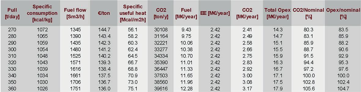
Figures 2 and 3 have been obtained by changing the pull while keeping the rest of the input parameters constant. We assumed the nominal point at 340 tpd and, for the purpose of this article, we did not change the electrical energy utilisation. Such param-
GREENER FURNACE 58 Furnaces International March 2023 www.furnaces-international.com
Figure 2. The table shows what happens to the parameters when the pull is changed.
Figure 3. Results in the graph show that the more the pull increases, the more CO2 is emitted.
eters would have been changed in common furnace operational practice.
Results show that the more the pull increases, the more CO2 is emitted and the more the consumption and operating costs are. Though, at the same time, specific consumption decreases together with quality expectations, which is connected to the minimum residence time rather than to the average, which is steadily defined by pull and furnace geometry.
We therefore observe that, to limit specific CO2 emissions, we need to use large furnaces at their highest pull.
GREENER FURNACE 59 Furnaces International March 2023 www.furnaces-international.com
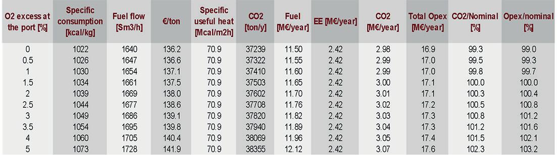
Figure 4. The table shows that the higher the oxygen excess at the port, the higher the CO2 emitted.
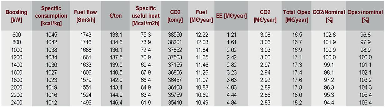
Figure 5. The table shows that increasing boosting corresponds to decreasing CO2 emissions.
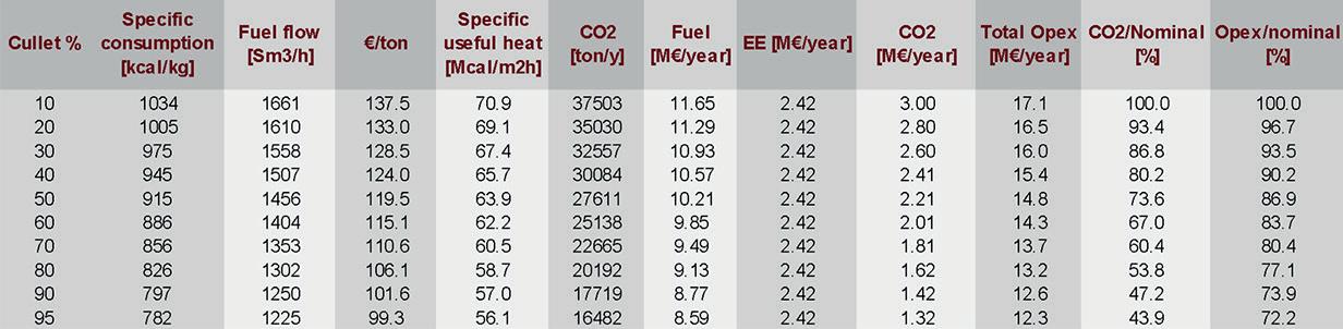
Figure 6. The results show that using glass cullet reduces CO2 emissions significantly.
TEMPERATURE AND HUMIDITY
Oxygen content
Figure 4 considers the oxygen content in waste gas at the port. It shows that the higher the oxygen excess at the port, the higher the CO2 emitted. Higher oxygen excess also means more consumption and operating costs.
However, the theoretical curve does not consider the following:
� At very low O2 level, combustion is not complete, and a certain quantity of CO is formed.
� Different levels of O2 correspond to different waste gas and air volumes.
� The higher the volumes are in the chambers, the higher the heat efficiency will be, but the lower the temperature efficiency of the chambers.
Nowadays this parameter is more under the spotlight for its connection with NOx and CO production rather than for its energy implications, but energy implications are important as well. To contain consumption and CO2 emission, we have to burn as stoichiometric as possible.
Boosting
Figure 5 shows the effect of increasing boosting from 600 to 2000 kW on the parameters.
The heat coming from the boosting is directly transferred to the glass heating it up with a better efficiency. Therefore, increasing boosting corresponds to decreasing the specific consumption, fuel consumption, and CO2 emissions.
Some barrier boosting is usually beneficial for the right formation of two opposing convective cells in the glass batch. Nevertheless, overuse of boosting may compromise the correct thermal profile of the superstructure and production itself. Also, an
GREENER FURNACE 60 Furnaces International March 2023 www.furnaces-international.com
increase in boosting means extra production costs.
While a high boosting decreases a furnace’s CO2 emissions, it has to be kept in account that the average fuel efficiency of a regenerative furnace is about 65%, while an average fossil power plant is 45%. Therefore, unless the electricity used in the furnace comes from renewable sources, more boosting means more CO2 in the environment.
Cullet
Using glass cullet reduces CO2 emissions as it reduces furnace consumption considerably. Cullet represents a portion of the glass mix that does not require the heat needed to transform raw materials into glass.
According to Fig 6, using 90% cullet reduces CO2 emissions by more than half. Less CO2 is emitted because melting cullet requires less energy.
However, external cullet utilisation is not an option for high quality extra-white glass.
GREENER FURNACE 61 Furnaces International March 2023 www.furnaces-international.com
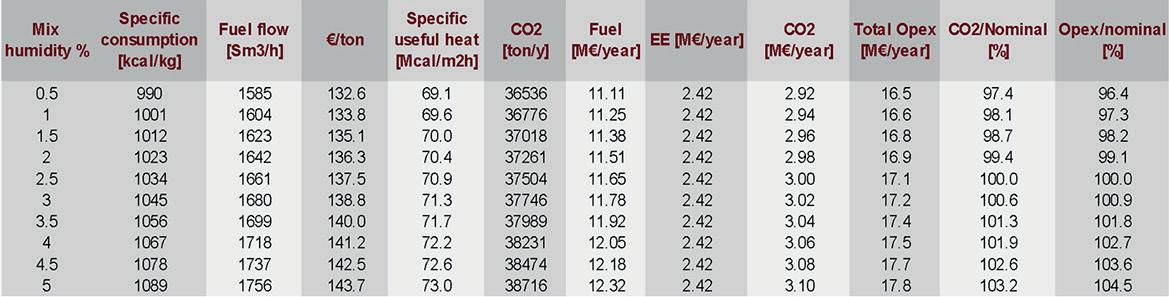
Figure 7. The table shows that increasing mix humidity increases CO2 emissions.
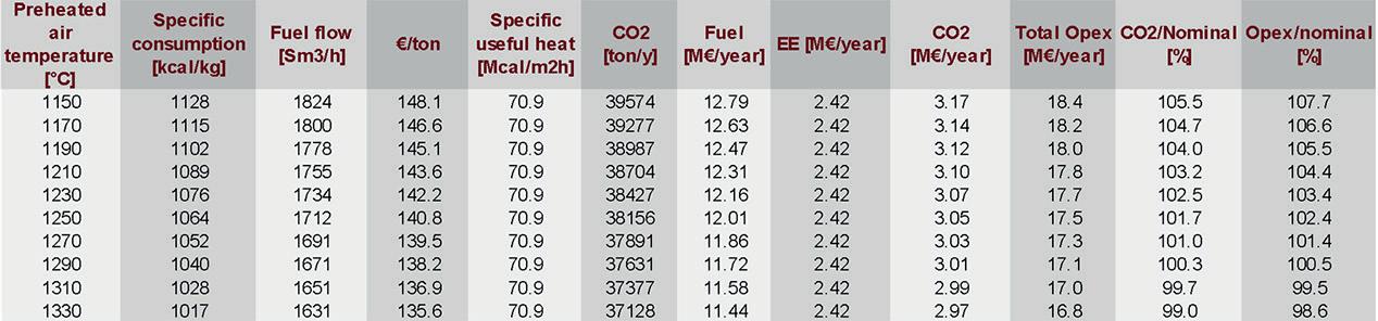
Figure 8. The results show that an increase in air temperature reduces CO2 emissions.
Overall, the higher the cullet, the lower the CO2 emission.
Mix Humidity
Figure 7 shows the effect of increasing mix humidity from 1.5 to 5% on the parameters.
Increasing mix humidity increases CO2 emissions caused by increased furnace consumption. This is because the batch mix water absorbs heat to become steam and reach waste gas temperature.
In fact, a covered storage area for raw materials can be a very beneficial investment. A low mix humidity, on the other hand, frequently promotes carry over problems.
Air Temperature
Fig 8 shows the effect of increasing air temperature from 1150 to 1350°C on the parameters.
An increase in air temperature means the reduction of consumption and CO2. This temperature can be increased at the highest level possible to increase furnace efficiency.
A contemporary melting glass furnace needs a performing heat recovery system.
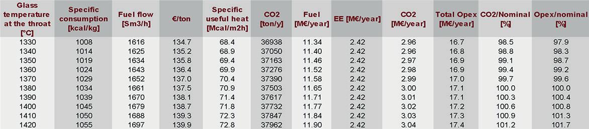
Glass Temperature
Figure 9 shows the effect of increasing glass temperature at the throat from 1340-1420°C on the parameters.
Increasing glass temperature obviously means more consump-
GREENER FURNACE 62 Furnaces International March 2023 www.furnaces-international.com
Figure 9. The table shows that increasing glass temperature increases CO2 emissions.
tion and consequently more CO2 emissions.
To reduce the CO2 emitted, this parameter can be maintained at the lowest level possible depending on the type of production and glass colour desired.
Conclusions
Glass furnaces are complex systems. Their performance in terms of energy, environmental performance, and glass quality is dependent on a range of characteristics.
However, there is still room for the designer to affect the reduction of CO2 they emit. For this transformation to be effective, it is critical to examine the desired glass quality as well as the cost of production.
To achieve decarbonisation, less energy should be consumed. Among all the parameters that reduce energy consumption,
cullet stands out as a parameter that can have a significant impact on the amount of CO2 released by the furnace; the more glass that is recycled and used in the furnace, the more efficient the furnace is, and less CO2 is emitted.
In fact, we have a message for glass producers: as humans, we surely prefer to drink our spirits and buy our perfumes in slightly green containers than to aggravate the climate emergency. �
Modernization and Transformation

INDUCTION MELTING AND THERMOPROCESSING PLANTS
See how new and existing, energyintensive industrial furnaces become part of a green market economy.
www.otto-junker.com
GREENER FURNACE 63 Furnaces International March 2023 www.furnaces-international.com
MELTING HOLDING POURING HEAT TREATMENT HEAT STORAGE RECYCLING AND MORE Experience our solutions at GIFA / THERMPROCESS June 12-16, 23 · Düsseldorf · Hall 10, Booth 10F57
Decarbonisation of secondary aluminium melting
Oxy-Fuel Combustion and Low-Carbon Intensity Fuels
By Anand
Makwana, Xiaoyi He, Russell Hewertson, and Martin Lawrence
This article was first published in the October 2022 issue of Light Metal Age
Introduction
Reverb or secondary melting furnaces are an effective way to achieve a global circular economy for aluminium supply. The recycling of aluminium uses up to 95% less energy compared to the primary production route, and global production of secondary aluminium has increased by 86% from 2000 to 2015.¹ In 2015, the total amount of secondary aluminium produced accounted for about 22% of the total global aluminium production.¹ This increasing trend in secondary aluminium production will continue to grow in the future as more aluminium becomes available through old scrap metal and aluminium manufacturers are pushed to reduce their carbon footprint to move towards net-zero goals. The increase in the secondary aluminium market size, along with the global effort towards decarbonisation, creates pressure on producers to find innovative ways to decarbonise their operations.
The need for decarbonisation of high temperature melting furnaces has bolstered interest in the use of oxy-fuel combustion systems and low-carbon intensity fuels. Both options provide a pathway to decrease the carbon footprint of new and existing furnaces, as they are suitable for retrofit. The use of oxy-fuel combustion helps to increase the overall thermal efficiency and production rate of a furnace.² This increase in efficiency helps to reduce the specific fuel consumption and, hence, helps to lower
GREENER FURNACE 64
Furnaces International March 2023 www.furnaces-international.com
the carbon footprint of the furnace operation. Additionally, use of low- or zero-carbon intensity fuels like hydrogen is another route to reduce carbon dioxide (CO2) emissions from furnace operations. It is important that the hydrogen is produced from a source that has a low-carbon intensity. The next generation of burners needs to be flexible so that they can operate using traditional fuels (e.g., natural gas) and mixtures of traditional and low-carbon intensity fuels (e.g., hydrogen, ammonia, etc.).
This paper focuses on the performance of the patent pending Horizontal Transient Heating Burner (HTHB) technology developed by Air Products. It discusses using oxy-fuel burner performance using conventional fossil fuels and mixtures of conventional and low-carbon intensity fuels in an industrial scale combustion furnace. Additionally, this paper presents results from computational fluid dynamics (CFD) simulations, demonstrating how the use of oxy-fuel combustion and the use of hydrogen as a fuel impacts the melting performance of a furnace. Theoretical and experimental data on CO2 savings and the impact of furnace atmosphere composition on refractory, performance, and aluminium quality using oxy-fuel systems (commercial installation results) and low-carbon intensity fuels (with CFD results) are also presented to enable manufacturers to choose the optimal solution to move towards decarbonisation for secondary melting furnaces.
Laboratory Test Results
The new generation HTHB technology is a double-staged transient heating burner that enables automatic control of energy into different locations of the furnace, based on feedback from
GREENER FURNACE Furnaces International March 2023 www.furnaces-international.com 65
strategically positioned sensors.3-4 The burner is designed to direct heat to cold areas of the furnace to increase thermal efficiency. For example, when the left-side flame is operating in active mode (delivering 70-90% of total burner heating capacity), energy is transferred to left side of the furnace (Figure 1a). When the right-side flame is operating in active mode, energy is transferred to the right side of the furnace (Figure 1b).
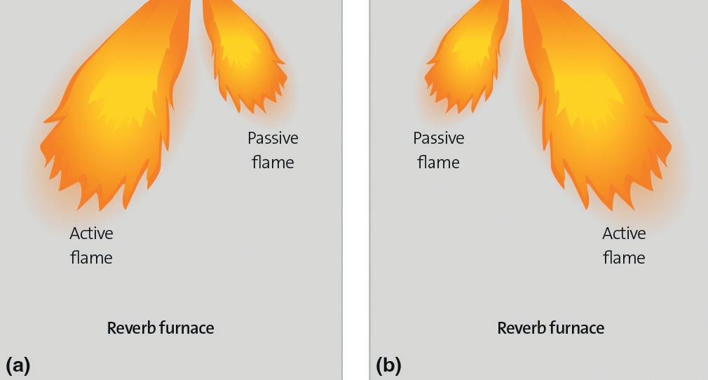
The HTHB technology is also configured for both fuel and oxidizer staging. The double staging achieves low nitrogen oxide (NOx) generation, which can be up to 40% lower than conventional oxy-fuel burners. The oxidizer staging of the burner also helps to reduce the oxygen near the bath surface, which can help avoid metal oxidation. In addition, the burner is fuel-flexible and can operate with traditional fuels (e.g., natural gas) and low carbon intensity fuels (e.g., hydrogen) and/or mixtures of different fuels.
The burner technology can be used in current air-fuel reverb furnaces as a retrofit burner. This burner can be used in conjunction with other air-fuel or oxy-fuel burners or as an independent oxy-fuel burner in melting furnaces for improved furnace
GREENER FURNACE 66 Furnaces International March 2023 www.furnaces-international.com
Figure 1
operation that can provide faster melt times, increased energy efficiency, fuel savings, and production increases. Additionally, the burner can be roof- or wall-mounted, where the two configurations can be used together in the same furnace to improve performance.
The HTHB oxy-fuel technology was tested in an industrial scale laboratory furnace at a firing rate of 5 million Btu/hr. The burner was tested in oxy-fuel mode using natural gas, hydrogen, and natural gas/hydrogen blends. Figure 2 presents photographs of flames during burner operation for different fuel types and operating modes. Figures 2a-b illustrate burner operation using natural gas with two fuel nozzles, with the left and right fuel nozzles active, respectively. The fuel-rich active flame promotes
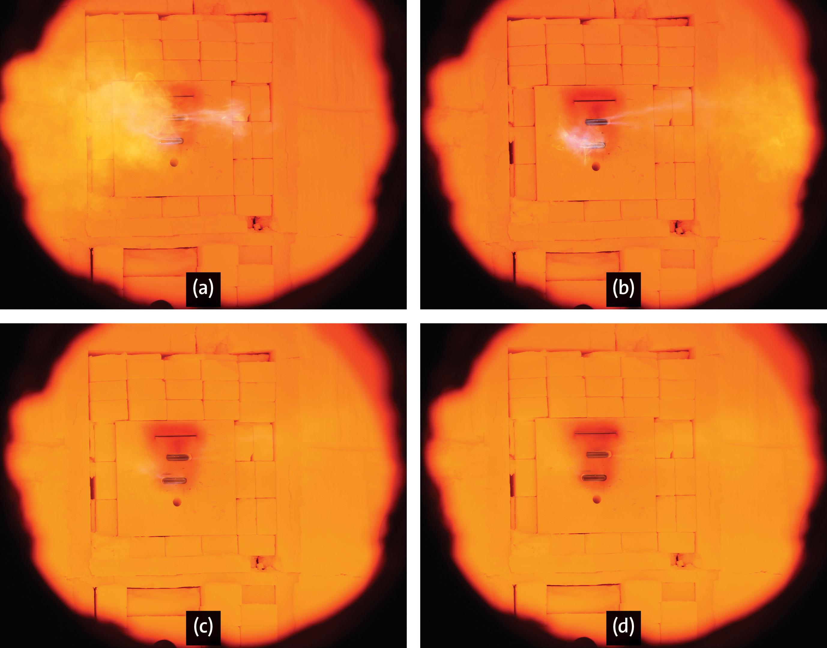
GREENER FURNACE 67 Furnaces International March 2023 www.furnaces-international.com
Figure 2
soot formation, thereby increasing the flame radiation and producing a local reducing atmosphere above the bath surface. By providing the flexibility for the burner to operate under dual operating modes (with one fuel nozzle being active while the other is passive or with both of the nozzles equally active), the secondary aluminium plant is able to adjust to their operating needs and adjust for changes in the fuel composition.
With the ability to operate with different fuels (natural gas, hydrogen, or mixtures of natural gas and hydrogen), the burner can be tuned to meet individual furnace requirements. Figures 2c-d show burner operation using a natural gas/hydrogen blend at two different compositions: 60% NG/40% H2 by heating value and 10% NG/90% H2 by heating value. When comparing Figures 2a-b to Figures 2c-d, the visible radiation of the flame can be seen to significantly decrease as natural gas is replaced with hydrogen, which can be attributed to the lower carbon content of the fuel.
Impact on NOx Emissions: In reverb furnaces, air leaks into the furnace during normal operation. This is because the furnace operates at slightly negative or neutral pressure compared to the external atmospheric pressure and is not airtight. This air influx results in nitrogen entering the furnace atmosphere. Additionally, in furnaces that use both air-fuel and oxy-fuel burners (e.g., in boost applications), nitrogen is introduced in the furnace from the air-fuel burner. This nitrogen interacts with the oxy-fuel flame, which forms thermal NOx.
The dual stage nature of the HTHB technology lowers the peak flame temperatures by operating away from the stoichiometric point, which reduces the NOx formation tendency of the burner.
GREENER FURNACE 68 Furnaces International March 2023 www.furnaces-international.com
Figure 3 shows a comparison of the normalized NOx emissions
(lbs/million Btu) between a conventional oxy-fuel burner and the HTHB technology, as a function of percent air leakage into the furnace. The HTHB results are presented for two cases with two different types of fuels: one with natural gas and another using a 70% natural gas/30% hydrogen mixture (by heating value).
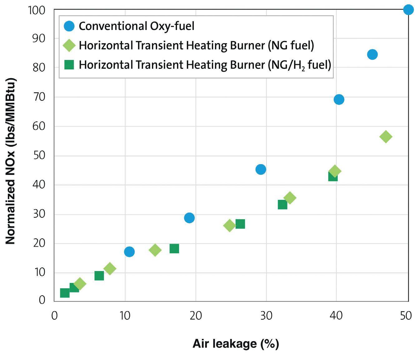
The HTHB technology is shown to generate lower total NOx emissions by as much as 40% compared to the conventional oxy-fuel burner. The total NOx emissions from the HTHB technology are similar when operated with natural gas or a mixture of natural gas-hydrogen fuel mixtures (taking into account measurement uncertainty and furnace operating factors). In addition, the CO2 emissions were below 15 ppm for all operating modes.
Results from Retrofitting Existing Reverb Furnaces
Existing reverb furnaces can be retrofitted with oxy-fuel burners to replace a portion of energy coming from air-fuel burners. This mode of furnace operation can be called a boost/hybrid furnace
GREENER FURNACE 69 Furnaces International March 2023 www.furnaces-international.com
Figure 3
CFD SIMULATIONS
operation where a furnace has both air-fuel and oxy-fuel burners. The use of oxy-fuel burners can help in two important ways: to increase the production rate of the furnace and to decrease the specific fuel consumption. For hybrid/boost applications, the location of air-fuel and oxy-fuel burners in the furnace is critical to provide optimal benefits. CFD simulations are generally used to identify the ideal locations of these burners to optimise the heat input to the melt and minimise the oxygen concentration near the bath surface, thereby improving metal yield.
CFD simulations were carried out to investigate the performance of a 62,000 lb capacity, natural gas-fired, aluminium remelting furnace for the purpose of increasing the production rate and reducing carbon dioxide (CO2) emissions. These simulations helped to understand how the replacement of an air-fuel burner with an oxy-fuel burner changes the thermal performance, exhaust gases, and key aspects near the bath surface (oxygen, water vapor). Additionally, it showed how changing the fuel from natural gas to natural gas/hydrogen mixtures and to hydrogen impacts these key parameters.
The simulations included four scenarios, which compared the standard air-fuel design with hybrid cases; firing natural gas, 30% hydrogen blended with natural gas, and 100% hydrogen. The CFD simulation results are shown in Table I
The furnace design for the base case scenario (using a standard air-fuel burner) had two sets of 10 million Btu/hr regenerative-type burners, firing a total of 20 million Btu/hr into the furnace. The melting time was 4.1 hours, with a specific fuel consumption of 1,328 Btu/lb of material charged into the furnace.
The remaining three hybrid/boost cases replaced one set of regenerative burners with the dual-staged HTHB oxy-fuel tech-
GREENER FURNACE 70 Furnaces International March 2023 www.furnaces-international.com


GLASS SERVICE Are you looking to the future for CO2 reduction? Then look no further than FIC... Tying Technology Together The eventual solution is hybrid fur naces operating at up to 80% electricity BUT small steps increase electric boost to reduce the CO2 then superboost. GS and FIC are THE companies to supply CFD modelling of your flexible future fur naces. FIC ...the pathway to a cleaner future www.fic-uk.com +44 (0) 1736 366 962 The World,s Number One in Fur nace Technology FIC (UK) Limited Long Rock Industrial Estate, Penzance, Cornwall TR20 8HX, United Kingdom
nology. The HTHB was sized to fire at 11.6 million Btu/hr to target a production increase of 25%, with a total firing rate of 21.6 million Btu/hr. The simulation showed that oxy-fuel combustion provided a significant improvement in melt rate.
In the first hybrid case, the HTHB utilised natural gas as the fuel. The use of the burner was found to reduce the melting time from 4.1 to 3.0 hours (compared to the base case), which provided a production increase of about 25%. Further, the oxy-fuel burner also provided a significant reduction in specific fuel consumption from 1,328 to 1,053 Btu/lb, a 20.7% savings versus the standard air-fuel case. The fuel consumption was directly related to CO2 emissions, whereby for every million Btu of natural gas burned, 116 lbs of CO2 are released into the atmosphere.5 The specific fuel consumption savings of 20.7% correspond to a reduction in CO2 emissions from 0.193 to 0.153 lbs CO2e/lb of aluminium charged. This shows that oxy-fuel combustion can be used to increase productivity, save fuel and reduce CO2 emissions.
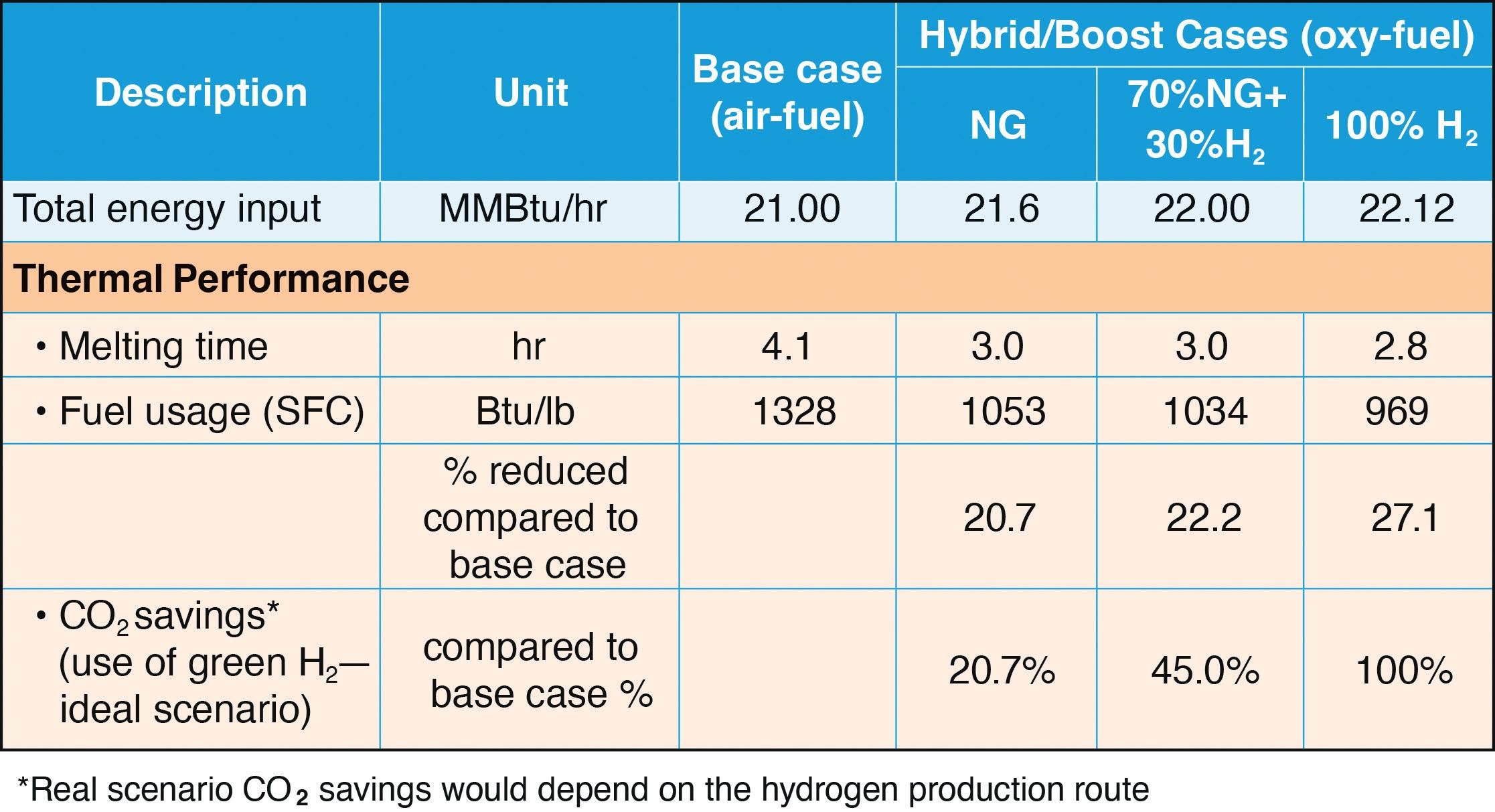
GREENER FURNACE 72 Furnaces International March 2023 www.furnaces-international.com
1
Table
In the second hybrid case, the oxy-fuel HTHB utilised natural gas blended with 30% hydrogen by calorific value as the fuel (70% NG/30% H2). The remaining set of air-fuel regenerative burners also used natural gas blended with 30% hydrogen by calorific value as the fuel. The hybrid system was able to maintain its productivity performance using the natural gas-hydrogen blend with a melting time of 3.0 hours (Table I). The specific fuel consumption slightly improved over the first hybrid case, reducing it to 1,034 Btu/lb, with a total of 22.2% savings compared to the base case. This can be attributed to the improved efficiency of the combustion of hydrogen as a fuel compared to natural gas. The addition of low-carbon hydrogen as a fuel significantly improved CO2 emissions savings, which can be reduced by as much as 45% versus the base case. This would be for an ideal case, where the carbon intensity of hydrogen production would be zero (0 lbs CO2/million Btu of hydrogen) and the resulting CO2 emissions would reduce from 0.193 to 0.105 lbs CO2e/lb of aluminium charged. However, for a real-life scenario, even the production of low-carbon hydrogen will result in CO2 emissions.
In the final hybrid case, the HTHB utilised 100% hydrogen as the fuel. The remaining set of air-fuel regenerative burners in this case also used 100% hydrogen as the fuel. The 100% hydrogen hybrid system was able to further reduce the melting time to 2.8
GREENER FURNACE 73 Furnaces International March 2023 www.furnaces-international.com
“
The increase in the secondary aluminium market size, along with the global effort towards decarbonisation, creates pressure on producers to find innovative ways to decarbonise their operations. ”
hours (Table I), corresponding to an increase in the production rate of 30%. The specific fuel consumption improved considerably more than the previous two hybrid cases, reducing to 969 Btu/lb, with a total of 27.1% savings from the base case, showing that hydrogen combustion can improve efficiency versus natural gas. In an ideal case, using 100% low-carbon hydrogen can eliminate CO2 emissions. However, as with the second hybrid case, the reduction in CO2 emissions is dependent on the conditions for producing low-carbon hydrogen.
For hydrogen to be considered low carbon, it must be produced by emitting less than a certain limit of CO2e/MJ of hydrogen. In Europe, this limit can be as low as 20 g CO2e/MJ of hydrogen (46.5 lbs CO2e/million Btu).6 There are several ways that the end user can receive hydrogen, including on-site generation, bulk deliveries, and pipeline. Bulk deliveries are typically unsuitable for delivering the quantities of hydrogen required for combustion in industrial furnaces, as significant quantities of either liquid or very high-pressure gaseous hydrogen would be needed. There is also the possibility of storing low-carbon or green ammonia on-site and cracking it into hydrogen prior to combustion, which would require liquid ammonia to be stored on-site and ammonia-cracking equipment to be installed. If the foundry is in the vicinity of a large hydrogen production facility, then it is possible to connect a pipeline directly to the site. Assuming these two options emit 20 g CO2e/MJ of hydrogen, both would result in a reduction in CO2 emissions of at least 37.9%, when comparing the base case to the 30% hydrogen hybrid case, from 0.193 to 0.12 lbs CO2e/lb of aluminium charged. It is recommended that data regarding the actual CO2 emitted during hydrogen production is collected from the hydrogen supplier to
GREENER FURNACE 74 Furnaces International March 2023 www.furnaces-international.com
calculate actual reduction in CO2 emissions.
When considering the options for on-site generation of hydrogen, electrolysis is the leading choice for low carbon hydrogen. If the foundry can take advantage of local wind or solar power, then it is likely that an on-site electrolyzer could make use of 8090% renewable energy to produce hydrogen, depending on local weather conditions. The remaining power can be drawn from the grid. In the case of an electrolyzer, the carbon intensity of the regional grid should be used to calculate the savings in CO2 emissions.
Additional Furnace Results: The simulation results also illustrated how the implementation of the HTHB and the various fuel types could impact the refractory wall temperature, oxygen mole percentage near the bath surface, and water vapor mole percentage near the bath surface using CFD simulations. The contours of wall temperature (Figures 4a-d) illustrate that the wall temperature increases in the boost cases as compared to the air-fuel
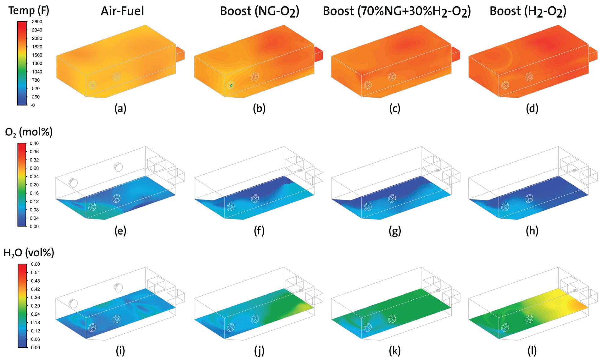
GREENER FURNACE 75 Furnaces International March 2023 www.furnaces-international.com
Figure 4
case, primarily due to higher peak flame temperature of oxy-fuel flame compared to the air-fuel flame.
Oxygen concentration near the bath surface is an important parameter to control, as stray oxygen can result in bath oxidation, thereby decreasing the metal yield. Comparison of the oxygen mole percentage (O2 mol%) contour near the bath surface in Figures 4e-h shows that the oxygen concentration stays relatively the same (~4-5% by mol%) between the air-fuel and the oxy-fuel boost cases. The transient nature, along with the dual-staged burner operation, helps to maintain the oxygen concentration to the base air-fuel case and hence, would not impact the bath oxidation adversely due to the use of oxy-fuel burners.
The water vapor concentration in the furnace is expected to change as an operation moves from air-fuel to oxy-fuel combustion, due to a decrease in nitrogen. This would further increase as the operation moves towards hydrogen-oxygen combustion due to the increase in water vapor (H2O) production from hydrogen combustion. Figures 4i-j illustrate that in the transition from air-fuel to oxy-fuel combustion using natural gas, the maximum water vapor concentration increases from about 20% to 30-35%. The transition of fuel from natural gas to hydrogen (Figures 4j-l) demonstrates that the maximum local water vapor concentration can increase to as much as 60%. It is possible that high water vapor concentration in the furnace atmosphere can be detrimental to product quality and yield and may influence the choice of furnace refractory material. This is an ongoing area of research when considering hydrogen as a fuel, and some operational and design constraints may be implemented to mitigate any risks once the problem is better understood.
A roof-mounted version of the HTHB was installed in boost
GREENER FURNACE 76 Furnaces International March 2023 www.furnaces-international.com
applications in multiple reverb furnaces globally.4,7 These installations were carried out using natural gas as the fuel, comparable to the boost case (NG-O2) shown in Figure 4. The results from these installations indicated that the change in water vapor concentration didn’t impact the melt quality, and the customers achieved productivity increases of up to 35%, up to 20% lower metal losses, and fuel consumption decreased by 45%.4,7 These real-world examples of using oxy-natural gas combustion illustrate that the secondary aluminium industry is ready to continue the further implementation of next generation oxy-fuel burners to improve performance and reduce CO2 emissions.
Conclusion
The use of oxy-fuel combustion systems and low-carbon intensity fuels, like hydrogen, provide a practical path to decarbonize and reduce the carbon footprint of secondary aluminium production. The lab-scale results demonstrate that the HTHB burner can operate with natural gas, hydrogen, and natural gas/hydrogen blends, while offering lower NOx performance (as much as 40%) when compared to conventional oxy-fuel burners. The flexibility of the burner technology can provide additional means to reduce the CO2 footprint by the use of low-carbon hydrogen. The actual CO2 reduction potential will depend on the hydrogen production route, which would in turn depend on the local geographic conditions (electricity mix, hydrogen availability, etc.).
The CFD results demonstrate that oxy-fuel technology provides significant efficiency improvements when shifting to hybrid operation compared to air-fuel burner systems. Additionally, the transition to oxy-fuel combustion maintains the oxygen concentration near the bath surface for all fuel types, indicating that the
GREENER FURNACE 77 Furnaces International March 2023 www.furnaces-international.com
use of oxygen and hydrogen may not reduce aluminium yield. Future field testing of the technology will include using hydrogen fuel blends to better understand the impact of higher moisture concentration on the metal quality and furnace refractory, if any.�
This article was first published in the October 2022 issue of Light Metal Age
References
1. “Non-Ferrous Metals,” Bureau of International Recycling (BIR), www.bir.org/the-industry/ non-ferrous-metals (accessed in August 2022).
2. Baukal, C.E., Oxygen-Enhanced Combustion, 2nd Edition, CRC Press, 2013.
3. Lawrence, M., et al., “Digital Twin Methodology Improves Performance and Yield in an Aluminium Tilt Rotary Furnace,” Light Metal Age, August 2020.
4. Sane, A., et al., “Secondary Aluminium News & Technology: Effective Use of Oxy-Fuel Combustion in Aluminium Reverberatory Furnaces,“ Light Metal Age, August 2018.
5. “UK Low Carbon Hydrogen Standard: emissions reporting and sustainability criteria,” U.K. Government, www.gov.uk/government/publications/uk-low-carbon-hy drogen-standard-emissions-reporting-and-sustainability-criteria (accessed in September 2022).
6. Gangoli, S., et al. “Oxy-Fuel Technologies and Strategies for Secondary Aluminium Melting Operations,” Light Metal Age, August 2017.
7. “Carbon Dioxide Emissions Coefficients,” U.S. Energy Information Administration, www.eia.gov/ environment/emissions/co2_vol_mass.php (accessed in September 2022).
GREENER FURNACE 78 Furnaces International March 2023 www.furnaces-international.com
THE LATEST FURNACE TECHNOLOGY NEWS

Furnaces International is an English language journal dedicated to the production of furnaces. Circulated each quarter in March, June, September and December to our database of over 20,000 readers across the Aluminium, Glass, Furnaces and Steel industries, Furnaces International contains a digest of global news, events, and statistics as well as more detailed technical articles, company and country profiles, and regular regional economic briefings.
Aluminium International

Today (AIT) is the leading bi-monthly English language journal dedicated to all sectors and regions of the international aluminium manufacturing and processing industry.
Subscribe to the free weekly newsletter at aluminiumtoday.com
Glass International o ers readers the latest news from across the hollow, container, flat, and speciality glassmaking industry and is the o icial media partner for Glassman events. In addition to 10 English language issues per year, it is also published in French and Spanish.
Subscribe to the free weekly newsletter at glass-international.com
PUBLISHED BY OFFICIAL PUBLICATION FOR


www.furnaces-international.com


Steel Times International is an English language magazine containing a digest of global news, events and statistics, as well as detailed technical articles, company and country profiles, conference reports and regular regional economic briefings.
Subscribe to the free weekly newsletter at steeltimesint.com
Sign up now to receive your FREE weekly Furnaces newsletter
ALUMINIUM FORUM DIGITAL