













03. Editor's comment
05. Pipeline news
Contract news and updates on CO2 transport agreements, Hydrogen Core Network funding and the Mountain Valley Pipeline startup.
KEYNOTE: SAFETY AND RISK MANAGEMENT
08. In the Red Zone
Alan Finlay, Chief Executive Officer, Salunda, explains how digitised Red Zone monitoring technology can improve personnel safety across the oil and gas industry.

HDD
15. The trenchless evolution
Stuart Stephens, Specialist Projects Director, Stockton Drilling, UK.
21. HDD Q&A
World Pipelines interviews Marvin Klein, Vermeer, USA; Meinolf Rameil and Lea Freise, TRACTO Technik, Germany; and Jeff Davis, Ditch Witch, USA.
COMPRESSORS, ENGINES AND TURBINES
28. A natural gas destination
Olivier Pellerin, Federica Furcas and Raman Hanjra, Baker Hughes.
COVER STORY
32. Total integration for flow assurance
Adam Murray and Kassie Stockton, Weldfit, USA.
SYSTEMS AND SOFTWARE
39. A profitable path to emissions reduction Dr. Jennifer Worthen, Emerson.
PIPELINE PIGGING
45. Beyond the bend Ross Dow, Propipe Limited, UK.
49. Focus on pigging: T.D. Williamson
COATINGS AND CORROSION
51. Coatings question time World Pipelines speaks to David Hunter, Segment Development Manager for CUI/High Heat & Insulation, Hempel.
PIPELINE STEELS: FABRICATION
53. Choosing a defence Philip Roscoe, N’GENIUS Materials Technology.


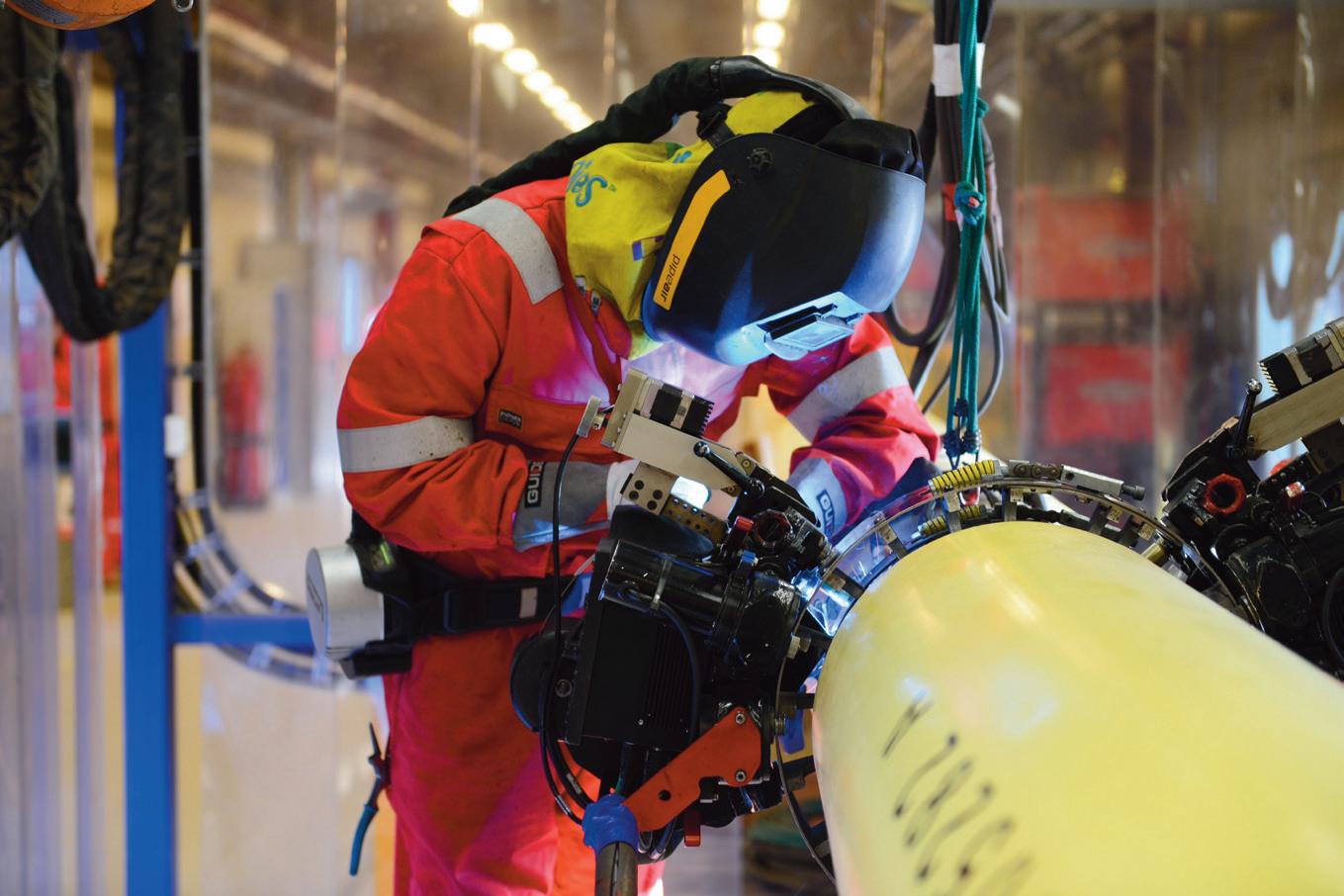
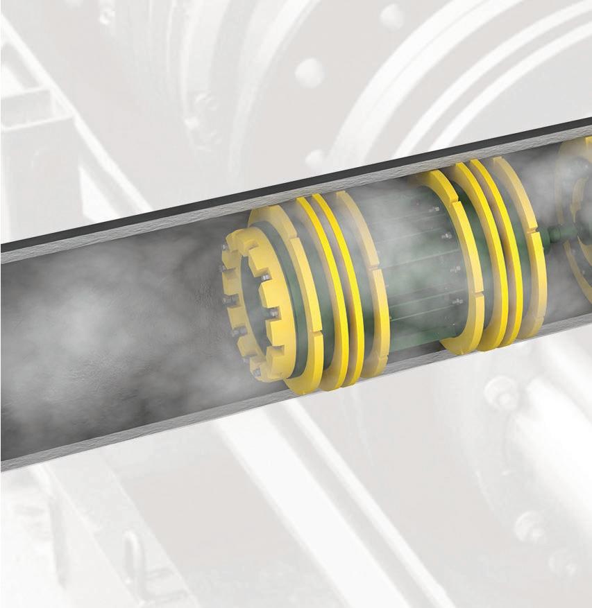
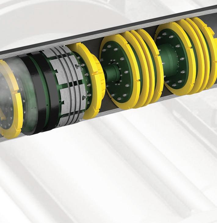
With a deep expertise and understanding of pipeline pigging and slug catchers, WeldFit introduces TOTAL INTEGRATION. This state-of-the-art solution brings together the functionality of the SureLaunch® multi-pig launching system and liquid slug management. This integration optimises and protects gas plant operations through automated, frequent pigging that reduces liquid slug size. WeldFit uses CFD modelling to reduce the required footprint of the slug catcher for operational efficiencies and cost savings.


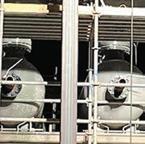
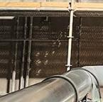
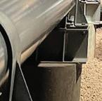










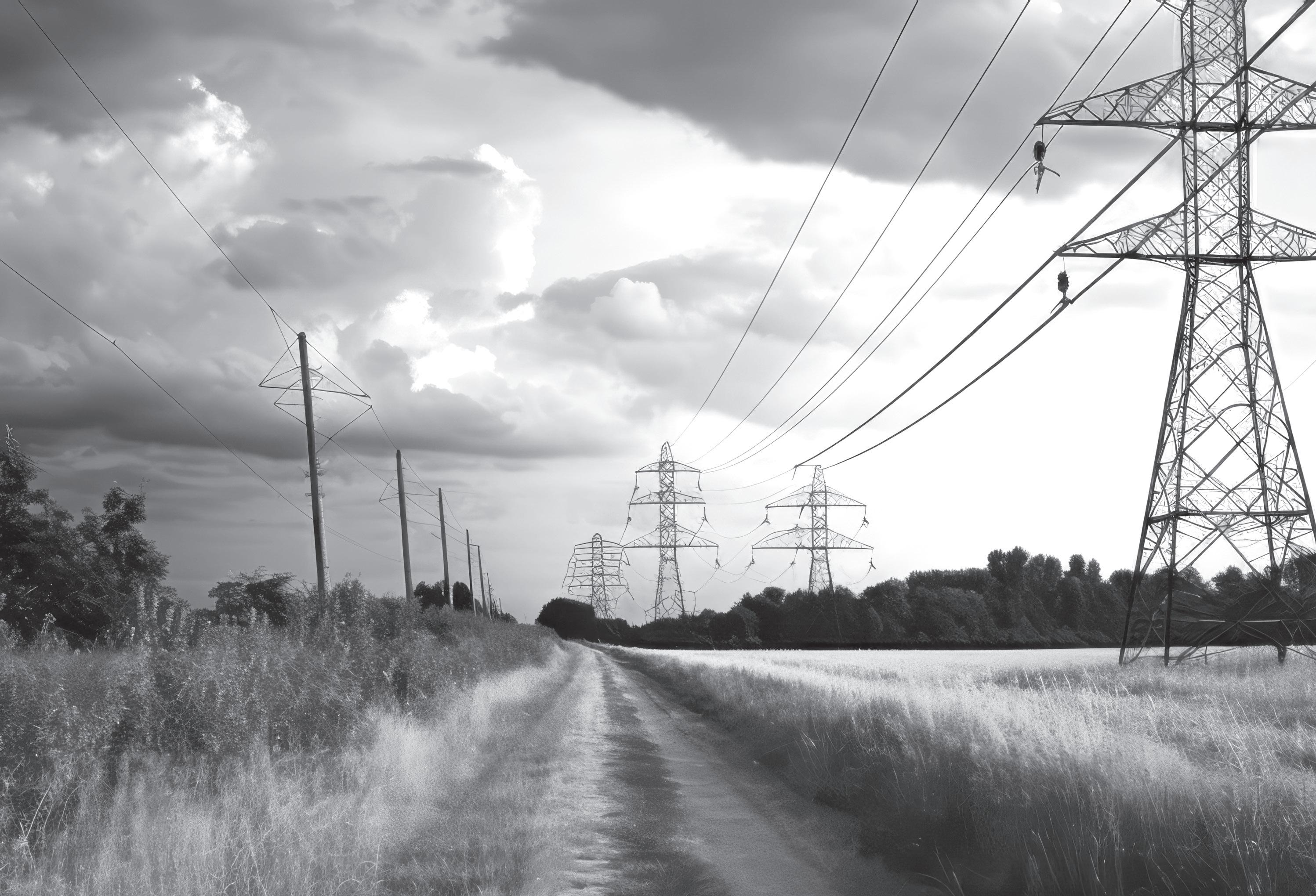
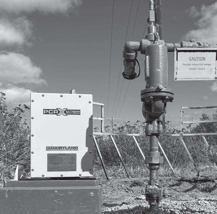
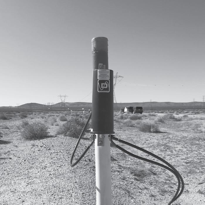
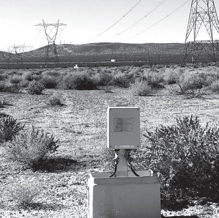
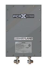
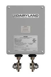
When your pipeline shares a right of way with high-voltage power lines, the electromagnetic field on the power lines can induce unwanted vol tage onto the pipeline, creating a safety hazard for personnel and contributi ng to AC corrosion problems. Dairyland decouplers provide an effective grounding path that mitigates induced AC, while simultaneously maintaining DC isolation to optimize your CP system. With a Dairyland decoupler, your CP system will continue to work efficiently, and the pipeline and personnel will be safe from AC interference.



MANAGING EDITOR
James Little james.little@palladianpublications.com
EDITORIAL ASSISTANT
Isabel Stagg isabel.stagg@palladianpublications.com
SALES DIRECTOR
Rod Hardy rod.hardy@palladianpublications.com
SALES MANAGER
Chris Lethbridge chris.lethbridge@palladianpublications.com
SALES EXECUTIVE
Daniel Farr daniel.farr@palladianpublications.com
PRODUCTION DESIGNER
Amy Babington amy.babington@palladianpublications.com
HEAD OF EVENTS
Louise Cameron louise.cameron@palladianpublications.com
DIGITAL EVENTS COORDINATOR
Merili Jurivete merili.jurivete@palladianpublications.com
DIGITAL CONTENT ASSISTANT
Kristian Ilasko kristian.ilasko@palladianpublications.com
DIGITAL ADMINISTRATOR
Nicole Harman-Smith nicole.harman-smith@palladianpublications.com
ADMINISTRATION MANAGER
Laura White laura.white@palladianpublications.com
Palladian Publications Ltd, 15 South Street, Farnham, Surrey, GU9 7QU, UK
Tel: +44 (0) 1252 718 999 Website: www.worldpipelines.com Email: enquiries@worldpipelines.com
Annual subscription £60 UK including postage/£75 overseas (postage airmail). Special two year discounted rate: £96 UK including postage/£120 overseas (postage airmail). Claims for non receipt of issues must be made within three months of publication of the issue or they will not be honoured without charge.
Applicable only to USA & Canada: World Pipelines (ISSN No: 1472-7390, USPS No: 020-988) is published monthly by Palladian Publications Ltd, GBR and distributed in the USA by Asendia USA, 701C Ashland Avenue, Folcroft, PA 19032. Periodicals postage paid at Philadelphia, PA & additional mailing offices. POSTMASTER: send address changes to World Pipelines, 701C Ashland Avenue, Folcroft, PA 19032

On 18 July, the Lifting Equipment Engineers Association (LEEA) will celebrate Global Lifting Awareness Day (search for #GLAD2024). The vision for this annual awareness day is that manufacturers, suppliers, and end users across all industry come together to share materials that promote safe and high-quality load lifting. World Pipelines has been happy to support GLAD for the last couple of years, as we appreciate their spirit of proactivity when it comes to educating personnel to lift safely, and we recognise GLAD’s work in sharing best practice that highlights how different sectors lift safely.
Safety is obviously at the forefront of everything our oil and gas pipeline community does. Lifting heavy sections of pipeline and steel tubes, with precision and care, is imperative in the pipeyard, when loading and offloading from machinery, and in the field.
On 18 July we’ll be posting on social media our top ten lifting-related articles as published in World Pipelines. We’ll be putting safety on show as we highlight pipeline companies using technology and systems to protect the working space and lift with accuracy. We’ll also be showcasing lifting technologies: one of these being vacuum lifting.
I recently had the pleasure of interviewing Bill Solomon, CEO at Vacuworx, about developments in pipeline lifting. We talked about the changing landscape for pipeline construction and associated project requirements, what we need to know about vacuum lifting technology and its place in the pipeline construction sector, and how the technology can adapt to the requirements of different types of pipeline builds. Bill was candid on how customer feedback leads to the development of technology and machinery. You can watch the interview by scanning the QR code on this page.
Here’s some recent lifting news:
) In May, Shanghai Zhenhua Heavy Industry (ZPMC) launched its JSD6000 deepwater lift pipelay vessel, equipped with a 5000 t fully rotating crane, for both J-Lay and S-Lay pipelaying systems.
) Next month, Mammoet will launch the world’s strongest land-based crane, the SK6000, capable of lifting up to 220 m and 6000 t. Huge cranes like this are used for things such as lifting offshore production modules onto FPSOs, and handling giant-sized equipment for the construction of offshore wind farms. High lifting capacity is crucial for the development of renewable energies.
) A new Liebherr Ram Luffing crane is now servicing Unity, an unmanned platform on the Forties Pipeline system and is specified with new fully electric handling and lifting solutions.
We’ll continue to shine a light on lifting hazards, safe lifting practices, regulations and standards, and more, in the pages of World Pipelines. In next month’s issue we focus on construction safety and project management, to coincide with the annual IPLOCA convention.

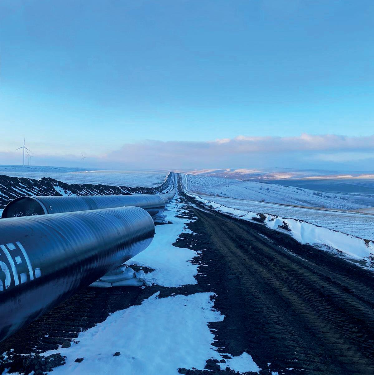
Founded in 1933, we cut our teeth in onshore and offshore pipeline construction. Now we are evolving our leading welding and coating solutions for today’s global energy and wider infrastructure sectors.
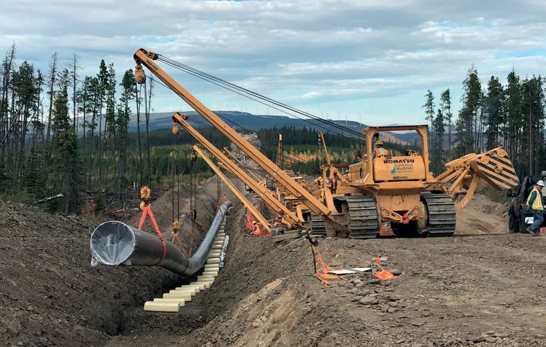
Mountain Valley Pipeline begins operation
Equitrans Midstream Corp. has put onstream a 303 mile pipeline from West Virginia to southern Virginia offering 2 billion ft3/d of natural gas transport capacity
On 11 June 2024, the Federal Energy Regulatory Commission (FERC) authorised the Mountain Valley Pipeline (MVP) to begin operations.
MVP, 303 miles long, can move up to 2 billion ft3/d of natural gas from Wetzel County, West Virginia (USA), to an interconnection with Transcontinental Gas Pipeline’s (Transco) compressor station 165 in Pittsylvania County, Virginia. Transco delivers natural gas through a 10 000 mile interstate transmission pipeline system extending from South Texas to New York.
MVP has signed long-term agreements with multiple shippers for the full capacity of the pipeline for at least 20 years from the in-service date. MVP will enable its shippers to access markets in
the Northeast, mid-Atlantic, and Southeast United States.
The project has faced legal battles over safety and environmental concerns and right of way disputes, which caused delays and inflated costs.
The 42 in. underground interstate conduit targets gas produced in the Marcellus and Utica shale plays, which sit in the United States’ top gas producing region of Appalachia. Equitrans said it hopes to capitalise on growing power demand in the midAtlantic and the Southeast regions through the pipeline.
In March 2024, EQT Corporation (EQT) announced the acquisition of Equitrans Midstream Corporation, operator of MVP, which will create a vertically integrated natural gas business in the Appalachian Basin with investments in natural gas production and transportation when the acquisition is complete. The transaction is expected to close during 4Q24.
The development will consist of a network of onshore CO2 pipelines, to be developed by GRTGaz, which will connect France’s Dunkirk industrial area to Equinor’s CO2 Highway Europe, a large-scale CO2 pipeline being planned by Equinor also connecting Zeebrugge, Belgium to a portfolio of storage sites under the seabed offshore Norway.
The project under the PDA aims to help decarbonise the Dunkirk industrial area which accounts for around 20% of France’s industrial CO2 emissions.
Specifically, GRTgaz will develop a 30 km onshore pipeline network in the Dunkirk region, a compressor station in Dunkirk sending the CO2 into the offshore pipeline connecting to the CO2 Highway Europe.
The capacity in the initial phase will be 3 - 5.5 million tpy of CO2, and the capacity can be expanded to also accommodate CO2 captured at other industrial clusters in France.
“For industries that cannot decarbonise directly through clean power, Carbon Capture and Storage (CCS) offers a viable solution. By building CO2 transport and storage solutions at an industrial scale together with GRTgaz we can help carbonintensive industries in France to continue developing and securing jobs and value creation in a sustainable future. The
collaboration also strengthens the viability of the CO2 Highway Europe project as the French connection will further strengthen economies of scale », says Grete Tveit, Senior Vice President Low carbon solutions, Equinor.
“GRTgaz is developing dedicated transmission networks contributing to transport CO2 from the French industrial sites where it is captured to storage and utilisation sites in France and Europe. Indeed, the capture, storage and utilisation of CO2 will play a major role in decarbonising the national and European economy, and infrastructure is an essential element in this CO2 value chain. We are proud to sign this partnership with Equinor and to share our respective and complementary expertise in order to provide France with an effective and competitive decarbonisation solution”, says Sandrine Meunier, Chief Executive Officer of GRTgaz.
Equinor and GRTgaz, with their complementary skills, will cooperate in the development of their CO2 transmission and storage infrastructures and associated services: network planning, technical design and industrial safety, interoperability, regulatory aspects and institutional relations. Feasibility studies are currently under way, with the aim of launching basic engineering studies at the end of 2024 and commissioning in 2029.
The European Commission has signed off on about €3 billion (US$3.2 billion) of planned German state aid for building a system of hydrogen pipelines known as the Hydrogen Core Network (HCN), reports Reuters.
Berlin plans to give financial guarantees to allow companies that build and run the €20 billion network to obtain more favourable loans to cover initial losses during the ramp-up phase from 2025.
Encouraging the uptake of hydrogen outweighs any distortion to EU competition and trade from the scheme, the Commission said on Friday 21 June 2024.
Germany’s ruling coalition agreed in April on the financing mechanism and extended the construction deadline by five
years to 2037, also offering protection for investors in case of bankruptcy.
Many countries are looking to hydrogen, which can be generated from wind and solar power for a more storable form of green energy, to help them reach net-zero greenhouse gas emissions.
Hydrogen is widely viewed as the only practicable carbonfree energy source for many processes in heavy industry, including the steel, chemicals, refining, glass and ceramics sectors.
Germany is targeting more than 9700 km (6000 miles) of hydrogen pipelines, with existing natural gas transmission making up 60% of the network to power heavy industry sites that cannot switch to electricity.
Phillips 66 to sell 25% stake in Rockies Pipeline
26 - 29 August 2024
ONS 2024 Stavanger, Norway www.ons.no
9 - 13 September 2024 IPLOCA convention Sorrento, Italy
www.iploca.com/events/annual-convention
17 - 20 September 2024 Gastech 2024 Houston, USA www.gastechevent.com
24 - 26 September 2024
International Pipeline Conference & Expo (IPE) 2024 Calgary, Canada www.internationalpipelineexposition.com
23 - 24 October 2024
Hydrogen Technology Expo Europe 2024 Hamburg, Germany
www.hydrogen-worldexpo.com
23 - 24 October 2024
Carbon Capture Technology Expo Europe 2024 Hamburg, Germany
https://www.carboncapture-expo.com
23 - 24 October 2024
Subsea Pipeline Technology (SPT) 2024 London, UK https://sptcongress.com
4 - 7 November 2024
ADIPEC 2024
Abu Dhabi, UAE
www.adipec.com/visit/registration
20 November 2024
Global Hydrogen Conference 2024 ONLINE www.accelevents.com/e/ghc2024
US oil refiner Phillips 66 plans to sell its 25% stake in the Rockies Express Pipeline (REX) for about US$1.28 billion, including debt, to a subsidiary of Tallgrass Energy, reports Reuters.
“This sale is an important step in our commitment to deliver over US$3 billion in asset divestitures,” Phillips 66 CEO Mark Lashier said in a statement.
REX, a 1714 mile (2758.42 km) pipeline system, is one of the largest natural gas pipelines in the US and provides over 5 billion ft 3/d of bi-directional natural gas transportation service between the Rockies, Appalachia and the northeastern United States.
The sale will provide about US$685 million in after-tax proceeds, the company said. Privately owned Tallgrass Energy operates the pipeline and owns the remaining 75% stake.
Sinopec unit agrees to build gas pipelines for Saudi Aramco
A Sinopec service unit said on Thursday 6 June, 2024, it has signed a 7.956 billion yuan (US$1.10 billion) deal to build natural gas pipelines for Saudi state oil company Aramco, reports Reuters.
The contract is for Sinopec Oilfield Service Co. to procure and construct the third-phase of the Master Gas System in Saudi Arabia, the Chinese firm said.
Sinopec will build parts of the pipeline grid that includes trunk lines with a total length of 2630 km (1634.21 miles) and 1340 km of branch lines, part of Aramco’s plan to expand gas distributions across the kingdom.
Under the deal, Sinopec is expected to complete construction by end of May 2027, the company said.
Vallourec signs major contract for Petrobras
Vallourec has secured a contract to supply Petrobras with 1800 t of premium carbon steel tubes with Glass Reinforced Epoxy liners (GRE technology), together with the associated topof-the-range CRA accessories.
These products will be used in various offshore development wells, mainly off the Brazilian coastline in the Campos pre-salt basin. This contract is in addition to the three year long-term agreement with Petrobras for the supply of OCTG tubes announced in January 2023.
Blackline Safety secures
CAN$8.5 million contract
Blackline Safety Corp. a global leader in connected safety technology, has announced is largest contract to date – a CAN$8.5 million deal to protect 1025 workers at a major North American midstream company.
The contract expands the company’s original CAN$3.5 million deal with Blackline – announced in September 2023 – to protect more than 850 workers. Combined with the previous deal, Blackline devices now protect all of the company’s nearly 2000 field and site workers.
The midstream company purchased 1025 G7 wearable gas-detection and lone worker devices, along with monitoring services. It also purchased 753 G7 Bridges to keep workers connected in remote areas via satellite.
• SENCO invests €20 million in Strohm
• ONEOK completes acquisition of Gulf Coast NGL system
• Some Colonial Pipeline owners explore stake sales at US$10 billion
• EU approves €3 billion in German hydrogen pipeline support
• Penspen announces strategic partnership with pipelinelogic
• Blackline Safety secures contract at CAN$8.5 million
Follow us on LinkedIn to read more about the articles linkedin.com/showcase/worldpipelines









Alan Finlay, Chief Executive Officer, Salunda, explains how digitised Red Zone monitoring technology can improve personnel safety across the oil and gas industry.
afety and reliability will always be two of the top concerns for workers across every stage of oil and gas production. While upstream, midstream and downstream operations all come with their own unique challenges, ensuring personnel are protected from harm while on duty in this safety-critical industry remains a constant.
Many workers at each stage of the production process will be required to perform tasks in the presence of heavy machinery and hazardous processes, creating environments with a myriad of potential dangers.
Which is where Salunda’s patented digital Red Zone monitoring technology comes into play. Already effectively deployed throughout upstream applications, the potential for Salunda’s wireless sensor and camera technology to be applied further downstream is considerable, promising enhanced safety and operational efficiency in the transport, storage and processing of oil and gas.

While the dynamic nature of offshore environments, especially on the drill floor, is rightfully identified as the main theatre of operation for Red Zone monitoring equipment, we have been intrigued and encouraged by the interest shown in similar safety solutions for midstream facilities.
Enhancing safety with wireless monitoring technology
Safety in high-risk working areas, like upstream drilling worksites, is a key focus for operators. The highly dynamic nature of work carried out on the drill floor, for example, heightens risk so personnel must be able to feel as safe as possible while working.
To this end, procedures and processes exist that identify where a specific zone is and what the associated risks are, alongside which personnel should be present in the area, and for how long.
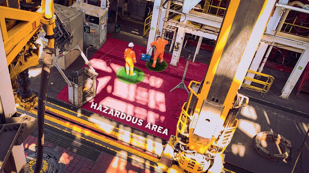
Monitoring technology, like Salunda’s ranging camera or wireless sensor solutions, helps increase situational awareness of when people are close to, or in, an active Red Zone.
If applied in a midstream setting, the wireless sensor technology can set up digital perimetres in any working environment around areas that pose the greatest risk to personnel and will review operations in real-time to ensure a worker is only in a Red Zone area for as long as they absolutely need to be.
If an individual were to enter a zone they are not authorised for, or they remain longer than they are scheduled to be there (for whatever reason), the monitoring technology will trigger an alarm that notifies both the individual’s personal locator and the area authority, allowing everyone to take the necessary corrective action. The same can be done with energised machinery, setting up a geofence that moves with the equipment, notifying the onsite worker if they enter one of these mobile zones. Making personnel aware of their own Red Zone violations, intentional or otherwise, can have a substantive positive effect on safety.
Salunda, having been established by a team from Oxford University in 2013, has worked with major oil companies and global drilling contractors to deploy in more than 60 upstream assets, and our inventions are protected by more than 100 patents.
Due to the specific materials handled and the processes involved in the transport and storage of oil and gas with pipelines, the midstream sector encounters distinct safety risks, which zone management can help to effectively address.
Personnel will likely be active in areas where they could be at risk of exposure to flammable gases, so it is clear that the number of workers operating within restricted areas should be kept to a minimum, and that exposure to these areas should be closely monitored.
With this in mind, it is imperative equipment used in these areas cannot be a spark or ignition risk. Salunda’s sensors, which are IECEx certified for use in flammable atmospheres, and DNV certified for use offshore, are made from polyether ether ketone (PEEK) plastics, a chemically inert material that doesn’t react to other substances. Clearly, this makes the technology an ideal fit for use in environments with exposure to pipelines and their contents. We have focused on inventing patented monitoring solutions that are simple to deploy and can be installed on a permanent or temporary deployment.
Red Zones in upstream worksites typically require a fixed monitoring system to be in place as these areas are strictly defined and are in constant use during operations. However, in midstream, while some tasks may require the












installation of a fixed digital monitoring system, it will likely be unnecessary for others.
Having a monitoring system enabled for the entire length of pipeline would be impractical, so having a flexible, ‘as needed’ solution is a better option. This is also the case when personnel could be exposed to hazards only for a short period of time when working, like when welding, cutting, lifting, bunkering or loading in an LNG terminal.
Portable systems can then be set up on a temporary basis, activating the geofence around the defined equipment or hazardous area for a specific amount of time. The sensors are also retrofittable with existing equipment within midstream facilities, reducing the installation time required.
There are several monitoring systems available to operators, some more complex than others. Many rely on GPS for location tracking data, which can determine the location of a person down to a 5 - 10 m radius. With Salunda’s patented HaloGuard LiDAR camera system, this accuracy can be up to 100 times greater. This isn’t overkill – by precisely locating personnel and work areas, it allows operators to have a much more accurate picture of what is happening on their asset.
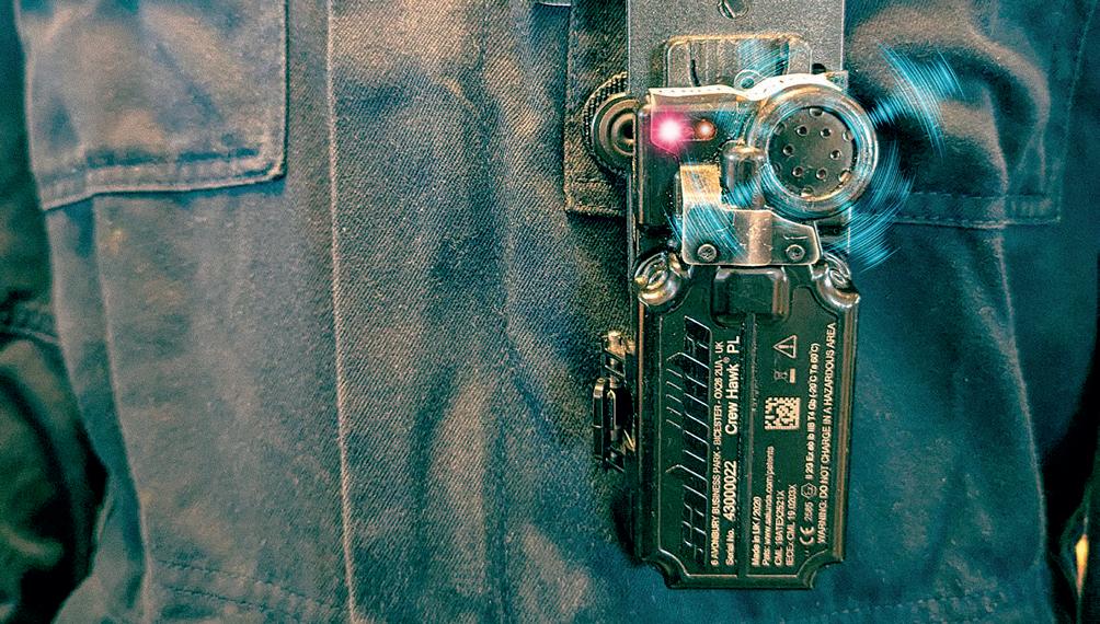
With wearable personnel locators (Salunda’s Crew Hawk system) and the 3D camera HaloGuard technology, systems can be set up and fully operational in hours. This is achieved using ranging sensors and structured data which triangulate the positioning of people and infrastructure in areas based on coordinates fed into the system, mapping out a 3D image. It can then calculate the distance between machinery, entrances/exits and personnel wearing locators in real-time.
Increases in precision can make all the difference if you are working in close quarters with others in a confined space and you want to avoid triggering an alarm accidentally, due to this lower margin of error.
With higher precision comes another important opportunity, the ability to remove human error from the equation while monitoring workers who could be in hazardous areas.
If an accident does occur, it’s easier to establish what really happened if we have a precise record that can help clarify a chain of events. We have demonstrated that HaloGuard cameras, when used in combination with Crew Hawk’s location tracking sensors, can provide and capture information that a human spotter may miss. The technology allows us to locate every individual in the work area and conduct a detailed analysis. It will track movements, identify roles within the team and confirm their authorisation.
Personnel can be pinpointed in real-time using cameras that identify a 3D set of coordinates, which is then compared with the information coming from the wearable sensors.
If a match is not found, it means there is an unauthorised person in the designated area. The system will then immediately notify the area authority and allow the necessary actions to be taken, ensuring that only the correct personnel are onsite.
We call it a ‘digital truth machine’, answering several essential questions – who, when, where, and what – all at once, without subjective experiences obscuring the facts.
The monitoring technology can also go beyond use for tracking personnel movements in Red Zones, becoming an Industrial Internet of Things (IIoT) solution that offers realtime oversight of safety-critical equipment.
Salunda’s proprietary wireless sensors can be fitted to safety barriers, gates, doorways, valves and hatch covers, among other use cases, to detect if the status of the designated equipment has been changed or moved, i.e. opened or closed.
When coupled with wearable personnel locators for workers, this can be used to set up Red Zones that will ensure workers are alerted if they enter an active hazardous area.
For example, if several personnel were operating in a confined space and there was no room for anyone further to enter, a system could be set up so that they are notified if the entrance to the space was opened. They can also be fitted to railings or walkways and enabled to send notifications if they become loose over time.
Salunda focuses on developing technology that is robust with an ultra-long battery life, meaning it can be activated and remain in place for several years without intervention, and is retrofittable for infinite applications across a midstream space.
Across all aspects of industrial infrastructure, particularly in the energy sector, digitising monitoring in Red Zones enables better communication and coordination in high-risk areas and can allow for the automation of processes for compliance and reporting, ultimately reducing the risk of accidents.
In addition to the lessened risk of incidents with systems for real-time monitoring and alerts in place, those operating in these challenging environments will also benefit from improved efficiencies in communications, data analysis and predictive capabilities. This means that learnings can be carried forward and shared across the industry to mitigate risks in the future.
As the role of IIoT and AI become ever more prevalent, the digitalisation of safety processes will advance incrementally. While we should never abdicate control or assume technology is a failsafe, it is clear there are significant benefits in deploying cost-effective solutions that augment the safety culture that is the number one priority for operators around the world. Its potential is undoubtedly promising.



Stuart Stephens, Specialist Projects Director, Stockton Drilling, UK, explores the progression of drilling and trenchless construction methods, outlining safety requirements, sustainable practices and case studies on Direct Pipe technology.
In the dynamic realm of trenchless and traditional construction techniques Stockton Drilling Ltd (SDL) has a rich and varied history dating back several decades. In this comprehensive article, we will delve into the roots, evolution and current standing of SDL and how the company has played a pivotal role in shaping the landscape of drilling and trenchless methods nationally and internationally.
One of the key factors that sets SDL apart, is its relentless pursuit of technological advancements, from the early days of drilling by the seat of your pants to the modern era of precision engineering, sensors and awareness of the environment, the company has consistently embraced innovation as a means to enhance efficiency and safety in drilling and wider company operations.
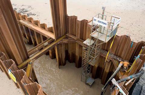
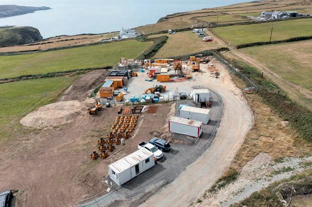
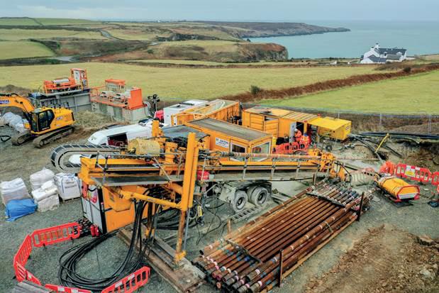
In the 2010s, SDL pioneered a novel use of the Herrenknecht Direct Pipe® system and the development of a remote subsea disconnect module: this allowed for the world’s first offshore wet recovery of a Direct Pipe tunnel boring machine. The technical leap not only increased the speed and viability of this and many other projects, but also significantly reduced environmental impacts, due to the ability of the system to be pushed onto the seabed for recovery and then the onshore clamping mechanism being able to retract the sleeve into the seabed. The ability removes the need for reception pits and associated works. The company’s commitment to sustainable practices was evident in its early endeavours, setting a precedent for responsible drilling and construction within the industry.
As the demand for energy resources grew globally, so did SDL. The growth has culminated in the formation of two internal divisions; the Civils division headed up by Geoff Morgan providing regional and national civil engineering services from design to completion and a Specialist Projects Division headed up by Stuart Stephens providing consultancy, design, and execution across trenchless and traditional construction with the ability for blue sky thinking and novel techniques.
The expansion into new territories has showcased SDL’s versatility and solidified its position as a go-to solution provider for a wide range of construction challenges with a notable focus on outfalls and landfalls.
The inherent risk profile of horizontal directional drilling and other trenchless operations necessitates a proactive approach to mitigating potential hazards. SDL’s safety protocols and stringent adherence to industry regulations have not only protected its workforce but have also set benchmarks for responsible drilling practices.
In addition to prioritising safety, SDL has consistently sought innovative solutions to minimise its environmental footprint including support to marine grass planting and donations to tree planting schemes, culminating in adherence with the Terra Carta mandate.
By embracing cleaner technologies and constantly refining its practices, the company has become a leader in promoting environmental responsibility within the oil and gas and energy industry.
At the heart of SDL’s success lies its skilled and dedicated workforce, many of which have been working there in excess of 15 years. The company places a strong emphasis on talent acquisition, investing in recruiting professionals with diverse expertise in engineering, geology, and environmental sciences. Continuous training programmes and staff retention ensure that the workforce remains at the forefront of industry developments and maintains the highest standards of proficiency.
to always deliver on my commitments, never underestimating the critical role that pipelines play as energy lifelines in fueling everyday life and unforgettable experiences.
It is who I am. I am a pipeliner.
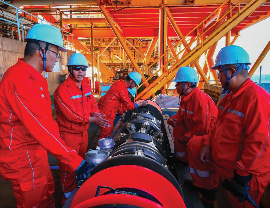
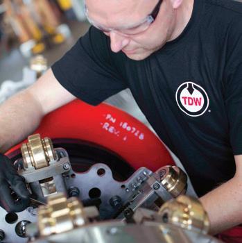

We are pipeliners too.
Keeping product in the pipe is a big job that’s critical to protecting the environment, especially when you’re offshore. TDW brings industry-leading application engineering teams, innovative solutions and world-class technicians to help you deliver on your goals. We remain committed to supporting you and the industry in moving toward a more sustainable energy future.
The world counts on you. You can count on us.
Case Study: Discover how our SmartPlug® tool enabled seamless riser replacement and topside modifications in the East China Sea.
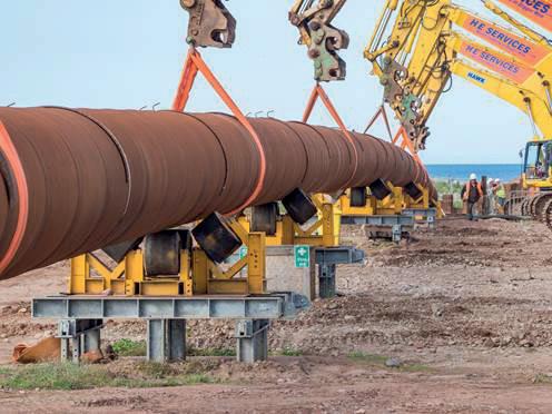
SDL has also been a pioneer in promoting diversity and inclusivity within its ranks. The company’s commitment to providing equal opportunities has resulted in a workforce that reflects a broad spectrum of backgrounds and perspectives. This diversity not only enriches the company culture but also enhances its problem-solving capabilities in the face of complex construction challenges.
The SDL team notably work best on groundbreaking schemes that push the boundaries. They have the engineering experience, expertise, judgement and communication skills to confidently interface with clients. This has resulted in long ongoing partnerships forming and with engineering judgement and experience to their clients have formed life long partnerships that will no doubt continue for decades to come.
Case studies: notable projects
) Robin Rig: Utilising its 250 t drilling rig SDL were able to drill 800 m through a layer of gravels near the entry point and a mixture of clay and sand under the beach and sabellaria reef. For the reaming phase a jack-up platform was installed offshore as a working platform, to contain the drill fluids a conductor casing was installed from the seabed and extended for 85 m at an angle of 9˚ complete with necessary temporary works supports.
) Beatrice: The Beatrice Offshore Wind Ltd. (BOWL) project was one of the largest private investments ever made in Scottish infrastructure and produces 584 MW from 84 turbines situated in the outer Moray Firth and powers approximately 450 000 homes at a cost of £2.6 billion to its investors SSE, Copenhagen Infrastructure and Red Rock Power. SDL completed the trenchless installation of two independent 48 in. x 450 m steel landfalls by utilising Herrenknecht’s Direct Pipe system (a world-first for this technology) and AVN1000 micro tunnelling machine.
) Tolmount: Contracted by Saipem to conduct the Onshore and intertidal Civil Works of the Tolmount Area Development Project. To facilitate the landfall of the new gas pipe over 20 000 m 3 of earth was dug and
stored to facilitate access to the beach, a cofferdam over 180 m long was constructed directly into the North Sea, a winch with a capacity of 550 t was set up to facilitate a direct pipe pull from the lay barge into the cofferdam, subsea tunnel and ultimately to the base of a 20 m deep vertical shaft
) Northern Endurance Partnership: For the UK to meet the net-zero goal of CO 2 emissions it is necessary to capture and sequestrate both Teesside and Humberside’s emissions offshore. Responsible for concept engineering and ultimately Front-End Engineering and Design of six separate landfalls utilising Direct Pipe, HDD and open cut depending on the installed product pipe/duct diameter.
As of 2024, SDL stands as an emerging global and European leader in drilling and trenchless services, with a diverse portfolio of projects spanning the entire spectrum of nuclear, oil, gas, water, and carbon capture. The company’s commitment to innovation, safety, and environmental responsibility continues to drive its success and shape the industry’s future.
Looking ahead, SDL is already capitalising on being the UKs only owner operator of the Direct Pipe system (in addition to its existing trenchless fleet) and on emerging technologies such as artificial intelligence, automation, and machine learning to further enhance drilling and tunnelling efficiency and reduce environmental impact. The company’s proactive approach positions it as a key player in the ongoing energy transition, where sustainability and technological innovation are paramount.
Conclusion
SDL was founded in 2000 by Fiona O’Connell, who had a background in offshore dredging, trenchless crossings, and linear infrastructure. During its initial years, SDL focused on providing drilling services for onshore oil and gas projects. The company quickly gained a reputation for its reliability, efficiency, and emphasis on safety. This solid foundation laid the groundwork for its expansion into more complex and challenging drilling environments across the UK and further afield operating and designing in places such as Egypt, Azerbaijan, Japan, Norway, and Senegal.
The story of SDL is one of ingenuity, adaptability, and a steadfast dedication to pushing the boundaries of what is possible in the pursuit of sustainable and responsible construction practices. Capabilities are now broader than ever before and continue to expand with the ability to design and deliver complex trenchless crossings and landfalls using HDD and Direct Pipe technology.
Finally, the UK (and further afield) has a contractor that will not attempt to steer a client to a particular construction technique. They will review and analyse each project for its strengths and weaknesses and select a technique that provides optimum engineering value, followed by a detail design based on actual experience.
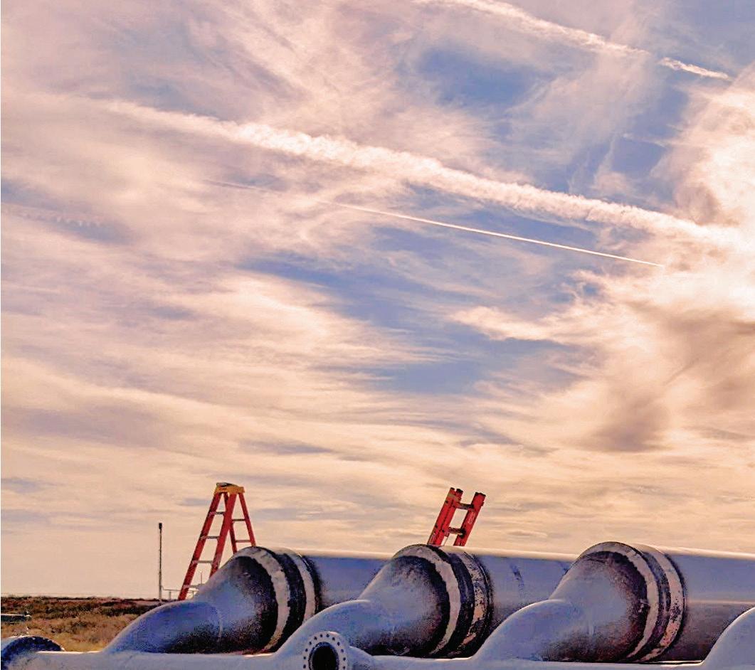


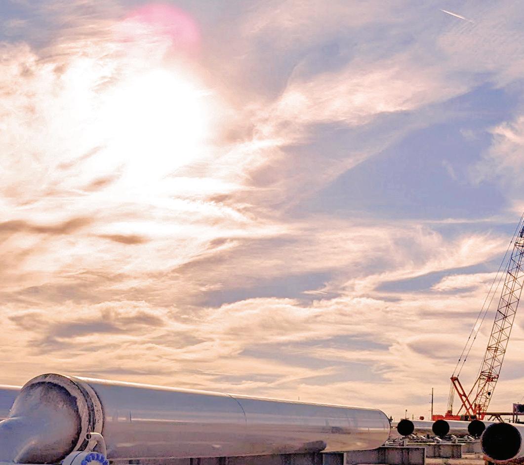


Considering that it takes pigs to move unwanted liquids through the pipeline to the slug catcher, pigging and liquids management have always gone hand-in-hand — even though pig launchers and slug catchers are usually miles apart.
The problem with this physical divide is that it’s easy to think one piece of equipment doesn’t have much to do with the other. This couldn’t be further from the truth.
By integrating its SureLaunch® Multi-Pig Launching System and harp-style slug catcher, WeldFit optimizes pipeline pigging and liquids handling for more control over risk, equipment costs, safety, and emission bringing you closer to your operational and financial goals. That‘s TOTAL INTEGRATION For more information, contact your WeldFit representative.




World Pipelines interviews some HDD experts about technological developments, the impact of environmental conditions and the future of HDD.
Marvin Klein, a dedicated member of the Vermeer Pipeline Commercialisation team, supports the Vermeer worldwide dealer network with sales and field support for the company’s trenchless product line-up. His focus is on the Vermeer line of maxi rig horizontal directional drills and related equipment. As an industry veteran, Klein also consistently shares his knowledge in promoting trenchless methods through many presentations and panel appearances. Before joining Vermeer in 1993, Klein worked as a drilling specialist and equipment coordinator for an underground utility company in Iowa.
Meinolf Rameil is CTO and Managing Director at TRACTO, and a renowned technical expert for underground pipeline installation and renewal. Lea Freise, a trained Mechanical & Welding Engineer, is Product Manager for HDD technology at the company.
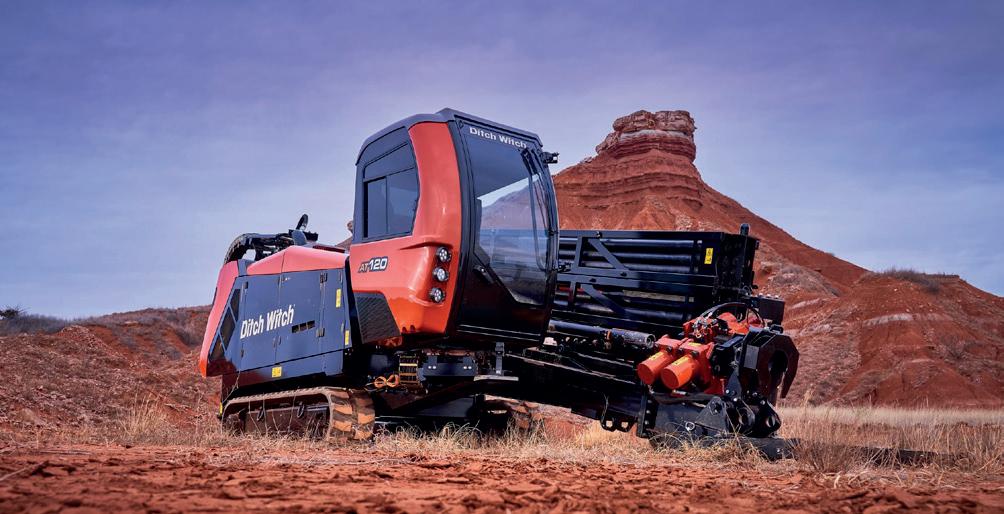
Serving multiple roles within the Ditch Witch organisation – from sales, to trenchless training instructor and product specialist, Jeff Davis has more than 25 years of valued customer experience and extensive underground construction knowledge. Currently the HDD Product Manager for Ditch Witch, Jeff is responsible for the management of the over 30 000 lb HDD lineup, to meet customer needs and provide solutions for underground construction professionals globally.
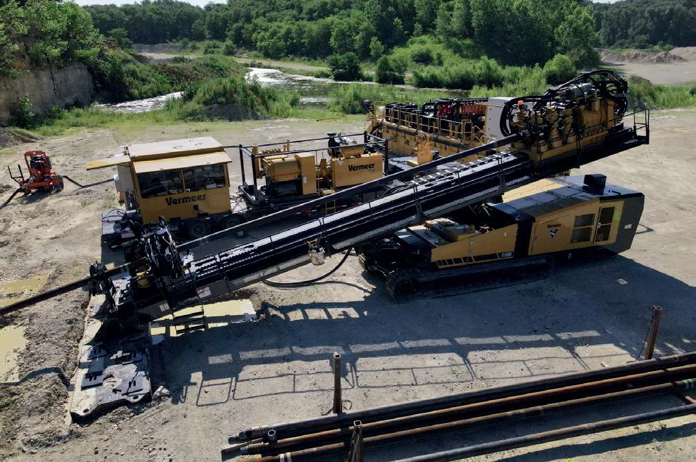
Discuss a recent HDD project for an oil/gas pipeline and describe why the HDD method was used. Marvin Klein, Vermeer: Vermeer horizontal directional drills are utilised globally for the installation of crude oil and natural gas pipelines, specifically in areas where open-cut methods are not allowed or desirable.
HDD is typically used in sensitive environments like wetlands, forests, rivers, and under roadways. This trenchless method minimises the need for restoration work after installation. The project owner makes the choice between open-cut or trenchless methods during the planning phase, and specialised companies execute the work.
Marvin Klein, Vermeer: The optimal conditions for HDD installation occur when the ground material is the same all along the path being drilled. When ground conditions are consistent, HDD crews can plan their drill tooling and fluid mix without making adjustments during drilling, helping drive project efficiency.
However, many long-distance projects do not have consistent soil conditions. Crews often encounter different layers of material as they go deeper or cover longer distances, which can create challenges in the boring process. As the bore profile changes crews may need to adjust their tooling and mud mixtures to match the materials they are working in.
Meinolf Rameil and Lea Freise, TRACTO: In principle, HDD can be carried out with modern drilling equipment in any type of soil, even in rock. It is important to choose the right size of drilling rig and drilling tools as well as an optimally adapted drilling fluid. In addition, it is fundamentally important to know the existing soil properties.
It is also mandatory to know whether and which pipes are in the vicinity of the drilling path. Contractors therefore have a duty to inspect the surrounding area for external pipes before
drilling. Finally, planning the drilling path is crucial. The path should avoid obstacles such as underground utilities and so forth. A well-planned drill path minimises the risks and enables smooth execution.
How have recent technological developments improved the HDD process?
Marvin Klein, Vermeer: Equipment manufacturers have started integrating advanced technology into their designs and machines to enhance drilling efficiency and productivity. The advancements are seen not only from an operator’s standpoint but also in the wireline or steering process used in larger HDD crossings.
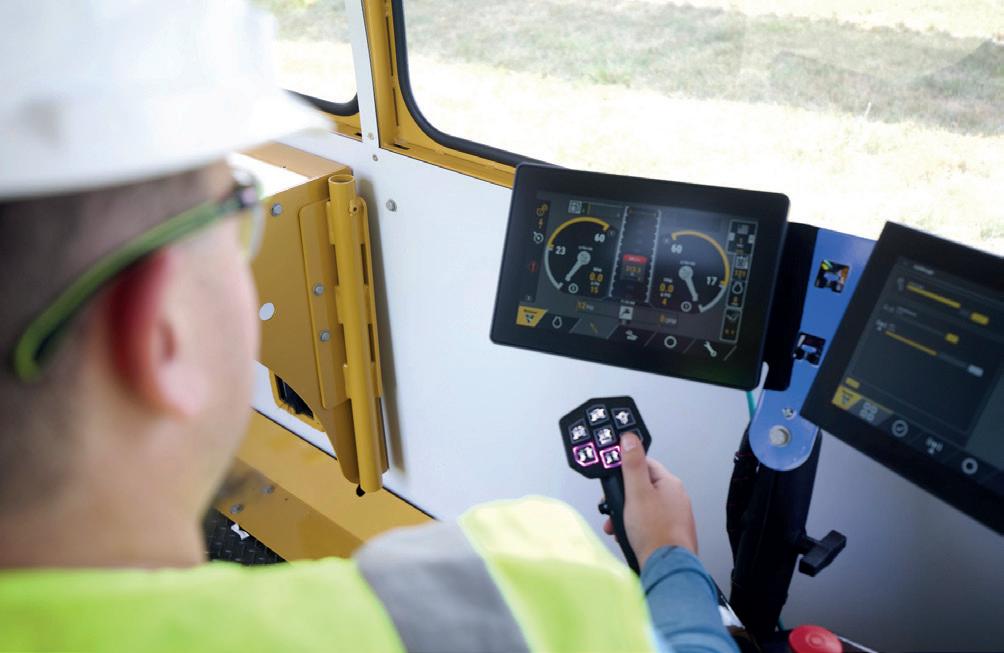
A key focus area has been the integration of technology into the machines, exemplified by the latest generation Vermeer maxi rig drills, the D550 HDD. The built-in software allows the drill to operate at its optimum capability. It offers three different auto-directional drilling modes – rotation, thrust, and speed – enabling operators to select the right mode for specific job requirements, further optimising productivity and simplifying the drilling process.
Another significant innovation is the D550 drill’s use of ultra-slow speed control technology. This technology enhances the drill’s performance in directional drilling in rock by providing precise control over thrust and optimising cutting action. It also helps to minimise equipment stalls, improve tooling life, and offers enhanced control to operators.
Meinolf Rameil and Lea Freise, TRACTO: HDD technology is becoming increasingly digitised with regards to planning, execution, monitoring, and documentation. TRACTO’s steerable drilling rigs already use a variety of support systems to make underground installation using the HDD method more efficient and safer, while at the same time collecting the necessary data on drilling and ground conditions for the client. Example: TRACTO has also developed the ORFEUS safe and effective obstacle detection system for horizontal drilling applications. ORFEUS is a drill head-based ground penetrating radar system that monitors the area around the drill head during the drilling process to prevent collisions and damage. This innovative tool will increase the safety and efficiency of drilling operations and is expected to reduce third-party damage to underground utilities significantly.
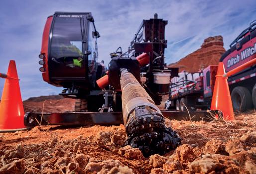
Jeff Davis, Ditch Witch: As demand for underground construction projects continues to increase, HDD operators are looking for ways to improve the efficiency, safety and profitability of the jobsite. However, the presence of hard rock often stymies the success of a variety of underground construction projects – until the advancement of HDD technology. To keep up with industry demand and increase jobsite performance, OEMs implemented key technological features to help contractors efficiently bore through tough terrain and improve efficiency and profitability. Jobsites that were once considered impossible due to the presence of rock were now possible with new HDD technology.
One key technology that changed the future of the HDD industry is dual-pipe drilling technology. Dual-pipe technology
can help operators reduce the risk of inadvertent returns, improve boring and steering through hard rock and provide a small footprint for compact jobsites. This means that mid-size drilling equipment now had the capability and power to push through rock.
However, no HDD installation can be made without the HDD tooling parts, such as downhole bits, drill pipe and backreamers. With the advancements of HDD technology, HDD tooling also evolved to provide better performance and functionality for contractors working in hard rock. For example, OEMs designed rock bits made with high-performance components to help extend bit life in hard rock conditions and technology that improved cutting structure and wear resistance. Contractors who understand the benefits of the enhanced tooling parts can be better prepared to implement them on the jobsite.
Discuss how HDD might impact the aboveground environment.
Marvin Klein, Vermeer: HDD is used to minimise the impact of construction work on the environment above. There are generally staging areas on each side of the bore for equipment and materials. In most situations, there should be minimal to no impact on the above-ground environment between these areas while boring. However, when working in inconsistent formations, mud management can be challenging, which can result in inadvertent returns of drilling fluids. When this happens, crews will often use vacuum excavators to clean up any drilling slurry
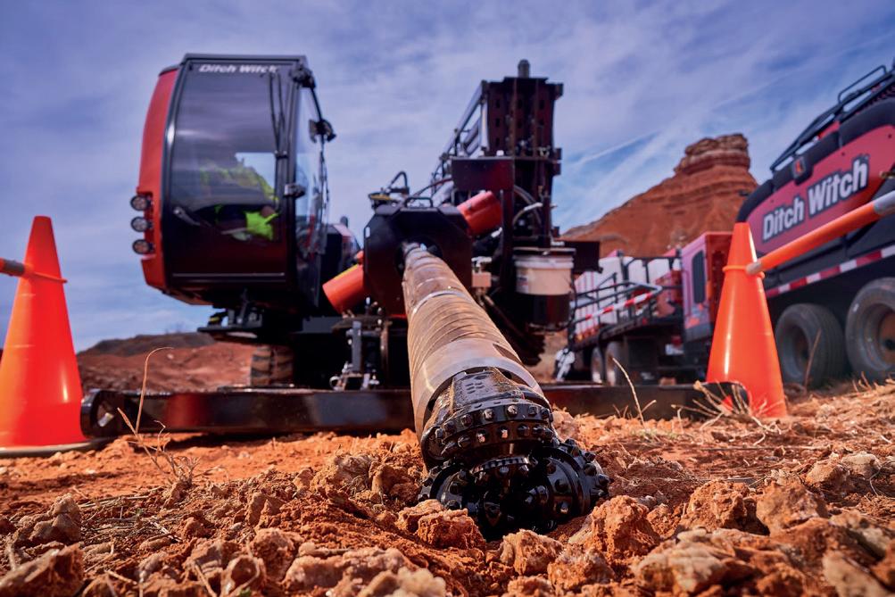


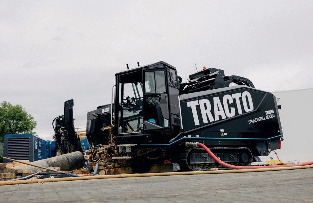
ATRACTO: The GRUNDODRILL ACS300 is the latest highly automated HDD rig from TRACTO with 300 kN thrust and pullback, enabling flexible pipe installation up to Æ 600 mm in all geologies, including solid rock.
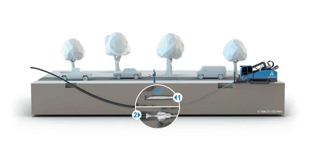
The
Meinolf Rameil and Lea Freise, TRACTO: In contrast to the open construction method, HDD is an environmentally friendly construction method. The surfaces between the start and end points of the borehole remain untouched and groundwater lowering is not necessary. Interventions in the ecological environment are reduced to a minimum. This is why HDD often is the method of choice in such areas. However, the method is also used in inner-city areas due to its low impact on traffic and residents compared to open construction, short construction times and low construction costs.
It can be assumed that approximately 70 - 80% of the construction costs of open trench construction are attributable to road and earthworks. Trenchless construction methods have great savings potential: depending on the project, the construction time can be up to 75% shorter, for example. Transportation for excavation and reinstallation of the soil can be reduced by over 90%. From an environmental point of view, it is particularly important that the consumption of valuable materials is kept to a minimum. In addition to the direct costs, it should not be forgotten that valuable surfaces are protected, residents experience significantly less stress due to noise and dust emissions and, as a rule, traffic can flow almost undisturbed on a trenchless construction site.
What challenges could occur during HDD installation? And how do you prepare for these?
Jeff Davis, Ditch Witch: As demand for underground construction projects continues to increase, getting the most from your equipment is vital to jobsite success. For HDD operators, drilling fluid plays a crucial role in efficient operations by removing
solids out of the borehole, lubricating downhole tooling, cooling electronics and stabilising the bore to prevent fluid surfacing out of the hole.
To assist HDD crews with their drilling fluid, manufacturers are utilising fluid cleaning systems. The goal of any fluid cleaning system is to remove as many solids from the drilling fluid as quickly and efficiently as possible. While these machines go by many names – drilling fluid cleaners, fluid cleaning systems, fluid recycling systems and mud cleaning systems – they provide many operational benefits. From minimising inadvertent returns and maximising downhole production to helping contractors reduce environmental impacts, fluid cleaning systems are the flux capacitor to the HDD jobsite.
Drilling fluids are a necessity to the HDD jobsite, but fluid cleaning systems are imperative to jobsite success. With the increase in environmental regulations and worker demand, fluid cleaning systems are not only helping solve contractors’ top fluid management pain points, but also increasing overall jobsite ROI. Adding a fluid cleaning system with a shaker screen can help contractors cut costs, minimise downtime caused by inadvertent return or haul-off trips and help improve overall jobsite productivity.
Marvin Klein, Vermeer: Drilling fluid plays a vital role during the boring process. It maintains bore path integrity, lubricates the path, and cools HDD tooling. So, the drill operator needs to monitor fluid pressure, while the crew keeps an eye on the volume of fluid returns. Excessive pressure can lead to inadvertent returns, and a sudden pressure drop may indicate fluid loss. Likewise, a low volume of fluid returns, relative to what’s being pumped down the hole, could suggest fluid loss during drilling. This scenario could potentially dry out the bore path, possibly leading to its collapse, the drill pipe seizing in the hole or damage to the product being installed.
On projects experiencing excessive fluid loss, crews must identify the cause and implement corrective measures. Often, they may need to modify their drilling fluid mixture. On many projects, crews will keep drill pipe in the ground after completing the pilot bore by running a tail string behind reamers and while swabbing the bore path. This strategy can help keep the hole open and provide crews access from both sides of the bore if the hole starts to tighten around the pipe.
Meinolf Rameil and Lea Freise, TRACTO: The biggest challenges when carrying out an HDD project can be the ground conditions and the number of existing pipes or cables in the immediate vicinity of the drill path. Therefore, well-trained, and experienced drilling personnel are required to avoid problems. As already mentioned, optimal information about the ground conditions and the existing installations is essential.
How do you see HDD developing in the future?
Marvin Klein, Vermeer: I anticipate ongoing advancements in equipment technology. Take, for example, the wireline systems frequently used in large scale HDD jobs. Recent developments have eliminated the time-consuming steps of having to feed and connect wirelines through every piece of drill pipe.
Onboard machine diagnostics is another important trend the industry is seeing right now. For instance, the Vermeer D550 HDD
incorporates this technology, providing drill operators and service technicians with easy access to vital diagnostic information. The onboard telematics allows for fast troubleshooting, ensuring that any issues that arise on the job site can be efficiently resolved. This advancement not only enhances productivity by reducing downtime but also simplifies the maintenance process, further contributing to the continued evolution of HDD methods and technologies.
Meinolf Rameil and Lea Freise, TRACTO: The long-term goal is fully autonomous respectively collaborative drilling to achieve more safety, more efficiency, more flexibility for companies, more sustainability and complete documentation.
Roughly speaking, the vision of autonomous drilling means that a horizontal drilling rig drills a hole completely independently in accordance with the planning specifications, documents it and settles accounts with the client. All components on the construction site are interconnected and communicate with each other. An ‘intelligent’ drilling rig of this kind can give advance warning of problems before they occur. The personnel will have monitoring tasks, whether directly on the construction site or via remote monitoring.
The path to autonomous drilling will lead via various intermediate goals, ranging from assisted drilling, which is currently being practiced, through partially autonomous drilling to fully autonomous and collaborative drilling enabling one operator to monitor several machines simultaneously from a control centre. At the end of the process, the vision is that only one operator will be needed, who will even be able to monitor several machines simultaneously from a control centre.
An important step towards greater safety in HDD, which is to be realised in the near future, is the aforementioned ORFEUS obstacle detection system, which will make it possible to use radar antennas to detect unexpected obstacles in the drilling process, such as incorrectly marked supply lines. The system evaluates the detected obstacles and triggers a warning or automatic interruption of the drilling process if necessary. The ORFEUS ground penetrating radar makes the HDD process even safer and is also a major step towards autonomous drilling; it will be ready for the market by Bauma 2025.
Jeff Davis, Ditch Witch: As advancements in HDD machines continue to improve, so does their tooling. But it’s not always easy to keep up with the latest developments in tooling as you work to meet tight project deadlines and deal with challenges like worker shortages.
AWhat’s more, even if you identify HDD tooling that’s a good fit for your machines, it can be difficult to justify the investment, especially if your existing tooling still works.
By understanding the advances that have been made in HDD tooling in recent years, and how they can improve both your jobsite performance and your bottom line, you can identify the best tooling for you and make a sound business case for buying it.
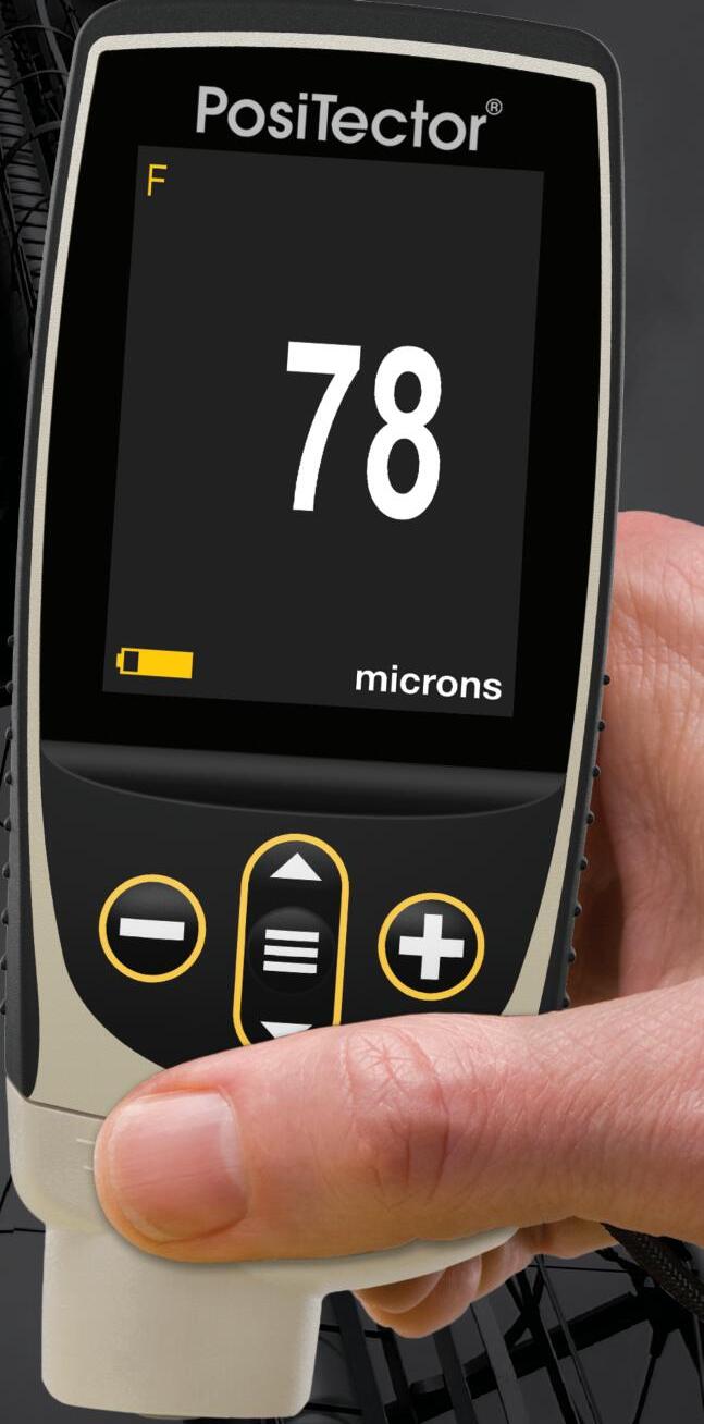
n Ready to measure—no adjustment required for most applications
n Fast measurement speed—60+ readings per minute
n Memory mode—Store measurement data, view live statistics, and analyze live graphs
n Included PosiSoft software—easily create professional inspection reports



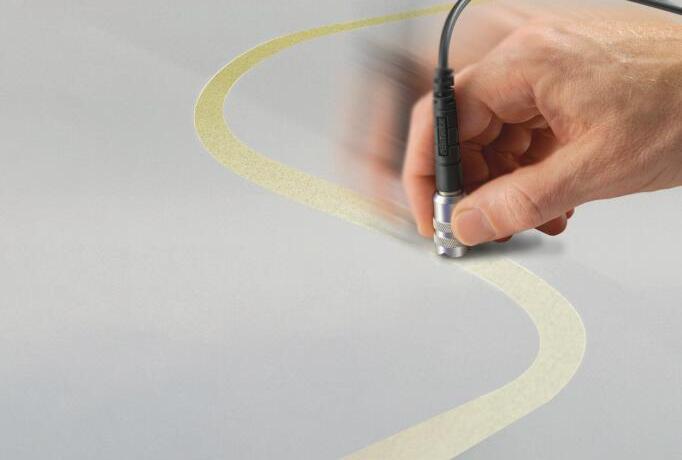


Advanced models feature 3 Scan modes to increase measurement speed to 180+ readings per minute
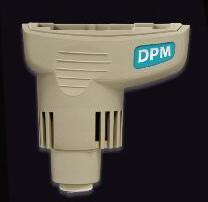
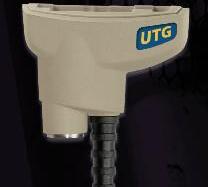
PosiTector gauge body accepts ALL coating thickness, surface profile, environmental, soluble salt, gloss, hardness, and ultrasonic wall thickness probes manufactured since 2012.


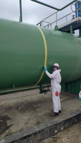
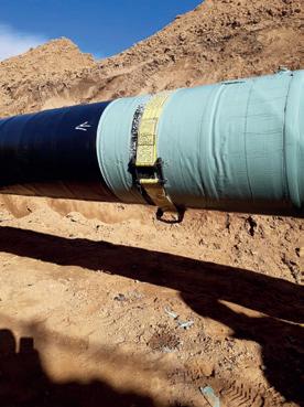
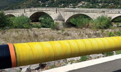
TANKi T®
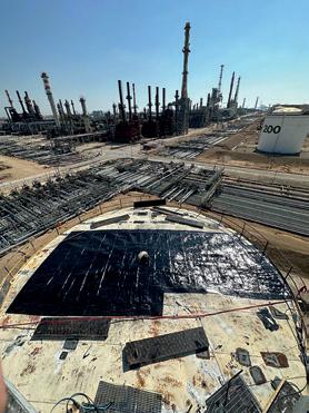
Emergency tank repair
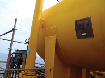
REINFORCEKi T® 4D
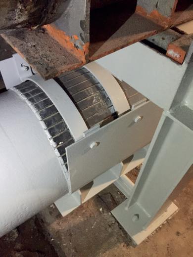
Pipe reinforcement
REINFORCEKi T® 4D
Riser reinforcement
REINFORCEKi T® 4D SUBSEA
Subsea pipe repair

REINFORCEKi T® STRUCTURE
Structural repair
STOPKi T® SUBSEA
Subsea leak sealing


Natural gas is not only key to the energy transition today but is a destination fuel for the future. The evidence today supports these long-term scenarios – global LNG demand is bullish, driven by significant growth in power usage.
However, providing secure supply for increasing demand is not the industry’s only challenge. We must provide energy in a sustainable and efficient manner to support the achievement of climate goals at a reasonable cost.
For the natural gas industry our primary challenge is methane emissions – the second largest contributor to global warming. Under the IEA’s Net Zero Scenario –which sees the global energy sector achieving net-zero emissions by mid-century, limiting the temperature rise to 1.5 °C – methane emissions from fossil fuel operations need to fall by around 75% by 2030.1
Policymakers and regulators have identified this challenge and taken steps to enforce change – the US introduced a tax on methane emissions, the Waste Emissions Charge, while the EU adopted earlier this year its Regulation on methane emissions reduction in the energy sector aimed to minimise leaks of methane by fossil energy companies operating in the EU.
Realising the IEA’s scenario and complying with new regulations will not be easy. Industry needs to identify how to meet increasing demand for natural gas, which, along with its infrastructure, is experiencing a new wave of expansion, whilst reducing major methane leaks at source along the natural gas supply chain.
Despite the scale of the challenge, our industry is more than capable of delivering. We have an obligation to act and we have the ability to do it. We need to demand more from energy, technology and ourselves. We already have the tools at our disposal. A proven portfolio of cost-effective technologies capable of cutting methane emissions exists today. One of these technologies is Integrated Compressor Lines (ICL).

Olivier Pellerin, Federica Furcas and Raman Hanjra, Baker Hughes, discuss reducing methane emissions across the natural gas value chain through Integrated Compressor Line (ICL) technology, drawing on a case study showcasing the ICLs in operation.
Integrated compression technology: simplicity to reduce venting and fugitive emissions
When we speak to our customers and partners about reducing methane emissions across the natural gas value chain, we are talking about opportunities unlocked by innovative technologies.
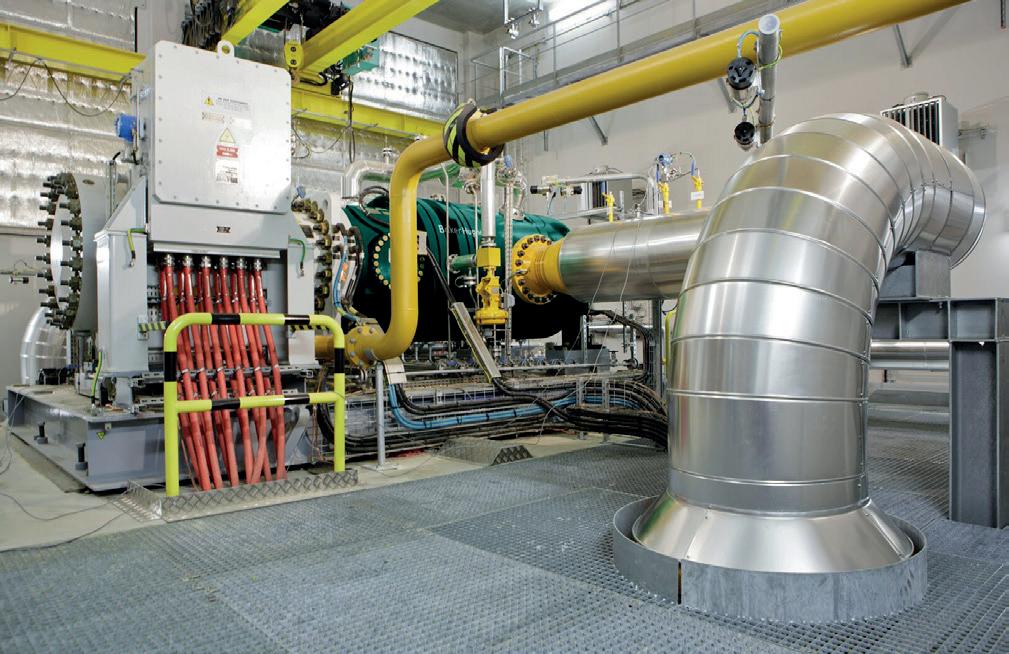
This includes ICLs, which reduce methane emissions while simplifying the compression stations operation by removing the risk of oil leaks and reducing fire hazard, increasing the safety of site staff, and minimising downtime.
Our 15+ years field proven ICL combines high-technology components in a simple, robust, and easy-to-operate system that eliminates the Dry Gas Seal (DGS) systems and their associated leakages. It is particularly advantageous for applications where high efficiency, small footprint, and low noise are important.
Let’s take a deeper look at how the Baker Hughes ICL technology works and what it delivers for our customers.
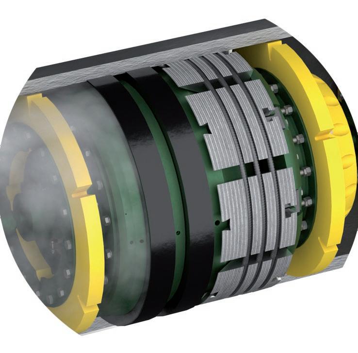
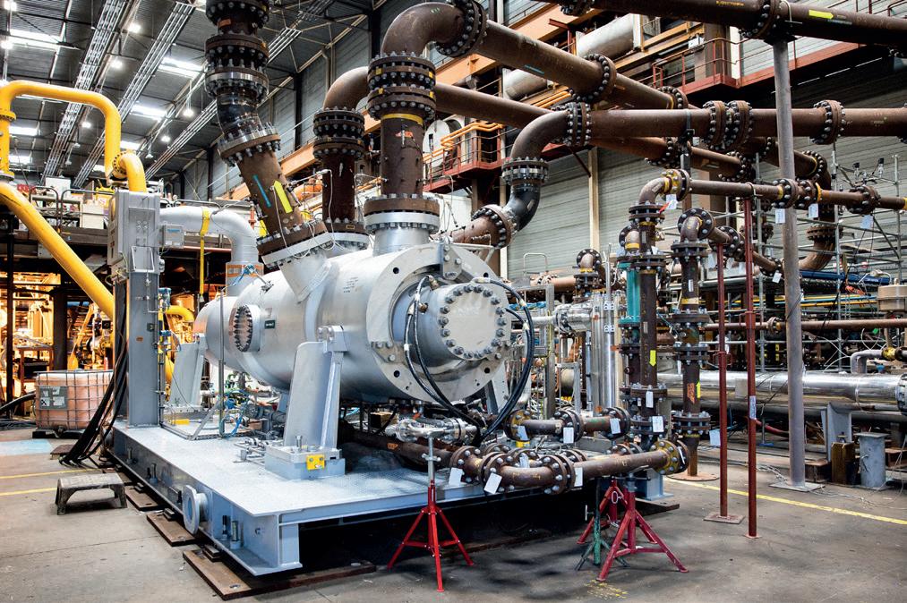
The ICL compressor is a centrifugal compressor driven by a high-speed motor installed together in a pressurised casing. The motor is cooled by the process gas inside the compressor, while the complete shaft line is levitated by active magnetic bearings, eliminating the need for a DGS system. This design mitigates leakage and enables unlimited pressure when the compressor is in standby, avoiding depressurisation in case of long machine stoppages and the resulting costly and polluting methane releases.
The gearless drive and magnetic-bearing shaft levitation combine to eliminate the need for lubrication – saving around 5000 l of oil every five years.
Thanks to the electronic Variable Frequency Drive which enables speed variation, the ICL guarantees smooth operation across a wide range of applications, covering speeds from 35% to 105% of nominal speed (almost double range compared to conventional compressor), which enables modulation of pressure ratio and inlet flow. On top of this, when in pressurised standby, ICL utility consumption is limited to minimal kilowatts of electricity (almost 10 times less than conventional), and it can go from standstill to full speed in less than five minutes, including warm-up time.
In addition, ICLs are significantly quieter than conventional compressors, as noise radiation is attenuated by the pressure vessel.
With a medium-voltage induction motor, ICLs can cover duties up to 20 MW. The machine is available in multiple architectures: one impeller overhung on the motor shaft, or multiple impellers in a single casing, arranged in one or two process sections (inline or in back-to-back). Eligible process gas is not limited to commercial natural gas, it can also process mild raw gas. The ‘full-size’ ICL is a compact configuration that is up to 50% smaller than conventional electric driven compression options.
The ICL range also includes a solution for power ranges below 1 MW with a low-voltage option, ICL-LV, that features industryproven, low-voltage, permanent-magnet motors. This is a smart, low-pressure solution ideal for flare-gas recovery, gas gathering, and micro-LNG applications. It’s particularly suitable for module integration with process and electrical equipment.
ICLs are also ideal for lifecycle cost optimisation. Its simplicity helps to reduce installation time and, with no wear parts or a critical auxiliary system, the compressor can go 10 years in cleangas applications without maintenance.
The design draws on more than 100 years of experience and innovation to deliver proven performance for clean gas and mild sour gas applications – in the upstream, midstream, and downstream segments. And over the past 15 years, we’ve been busy refining the opportunity and deliverables for our partners.
The impact of our ICL technology is not theoretical. We have worked with dozens of partners to improve efficiency and flexibility in their operations.
One example is Storengy, a subsidiary of the ENGIE Group, which is active in gas storage. Its aquifer storage site in Gournaysur-Aronde, France, used three compressors driven by gas turbines to store low-calorific-value (LCV) natural gas. During a transition period, Storengy will gradually provide less LCV gas, so the volume flow will decrease when the compressors will return to normal flow with 100% HCV gas.
To ensure a smooth transition and achieve its target for emissions reduction, Storengy wanted to replace one of Gournay’s largest turbine-driven compressors with a more flexible alternative. They selected Baker Hughes’ ICL technology powered by a 5.7 MW high-speed motor and its variable-frequency drive.
Without the need for lubrication, Storengy saves 5000 l of oil every five years, while the AMB enables operation at very low
speeds. Traditional compressor trains have an operating speed range of 70–105%, whereas ICL’s is 35 - 105% thus allowing the unit to operate at lower speed without recycling, nor wasting energy to laminate when operating low flow or low compression ratio. The VFD enables speed variation with top efficiencies over the entire range, which reduces power consumption. Thanks to this increased flexibility, Storengy can operate with both HCV and LCV gas without restaging the ICL.
The Gournay storage facility’s new ICL integrated motor compressor has better driver efficiency across a wider speed range than the previous turbine-driven compressor. Beyond process efficiency and performance, this project enables a strong step towards Storengy’s decarbonisation goals.
Even considering CO2 emissions from electricity production, and in part thanks to the low-carbon nature of the French electrical network, ICL will reduce Storengy’s CO2 emissions by more than 90% compared to the previous compressor unit. In the rest of Europe, replacing a gas-turbine-driven compressor with an ICL reduces CO2 emission by 60% on average.
ICL technology has been successfully deployed across a variety of applications including pipeline and offshore, with this Baker Hughes’ technology selected most recently by TotalEnergies in Aguada Pichana process plant located in the heart of Vaca Muerta, in Northern Patagonia, and by Società Gasdotti Italia for a pipeline application in Italy.
Of course, ICLs are only one technology in a portfolio of possible solutions for the decarbonisation of the natural gas supply chain, including for LNG.
Other technologies applied successfully in midstream, like ICLs, are also already in operation. For example, the Baker Hughes NovaLT™ gas turbine family, that are hydrogen ready, enable the use of existing gas pipelines to transport hydrogen-natural gas blends.
Conversions, modifications and upgrades also plays an important role. The proven ‘technology injections’ enable the reduction of carbon emissions while boosting asset performance from reducing operating costs to enhancing efficiency and plant output.
Finally, methane recovery system – a complete family of packaged single-lift solution – enables further emissions reductions by reducing gas venting and
flaring. It provides a flexible solution to our customers’ unique needs, as it can be either fixed or mobile (attached to a vehicle).
The success of our shared net-zero ambition depends on our ability to transport and store natural gas in the most efficient, decarbonised way.
The industry, through the deployment of readily available solutions, including Baker Hughes’ ICL technology, has the means to address the challenge.
References
1. https://www.iea.org/energy-system/fossil-fuels/methane-abatement

Adam Murray and Kassie Stockton, Weldfit, USA, describe taking the unique approach of combining multi-pig launching systems with slug catchers to improve the efficiency of pipeline operations.
eparating hydrocarbon liquids out of a natural gas pipeline serves multiple important purposes, including reducing impurities in the natural gas stream and preventing damage to costly downstream equipment.
Some pipeline operators use a slug catcher to manage the surges of liquid and gas, known as slugs, within pipeline systems and to separate condensate and other liquids collected as the gas moves from the production site to the processing facility. This means slug catchers are critical components in the oil and gas industry.
As such, there was nothing unusual about a midstream company active in the US Permian Basin looking to build a slug catcher at the terminal end of its 30 in. gathering pipeline. With a capacity of 10 000 bpd, the equipment would prevent the liquids flowing through one of its gathering pipeline systems from reaching critical equipment at the gas processing facility. What was different, however, was the WeldFit response.
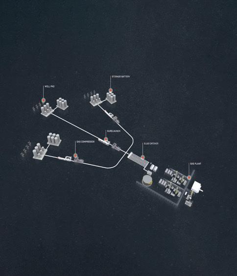
Traditionally, gas pipeline owners and operators have treated slug catchers and pigging systems as entirely separate from each other, partly due to their physical separation and partly due to the divide between midstream and downstream operations. Pigging systems were commonly described as ‘outside the fence’ – that is, treated as purely midstream infrastructure because they lacked direct connections to gas-processing facilities. By
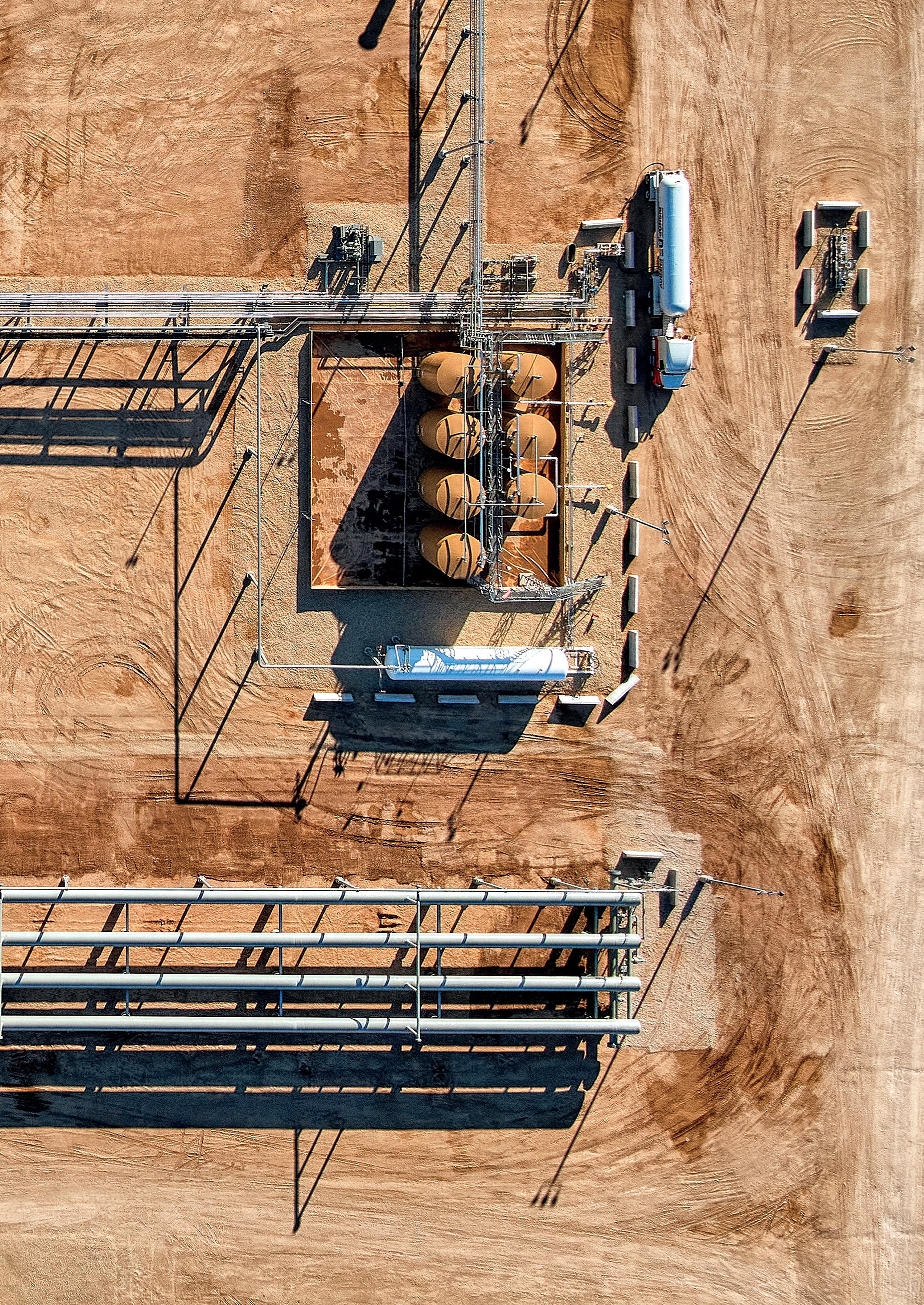
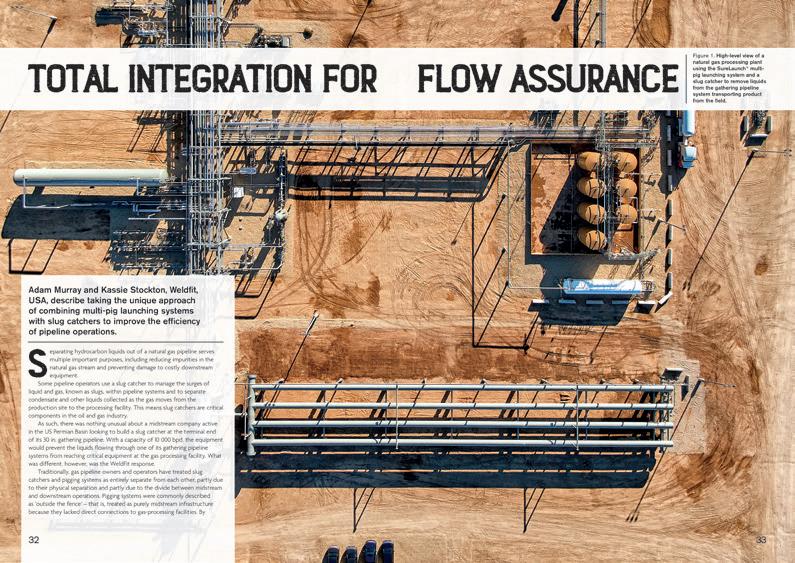
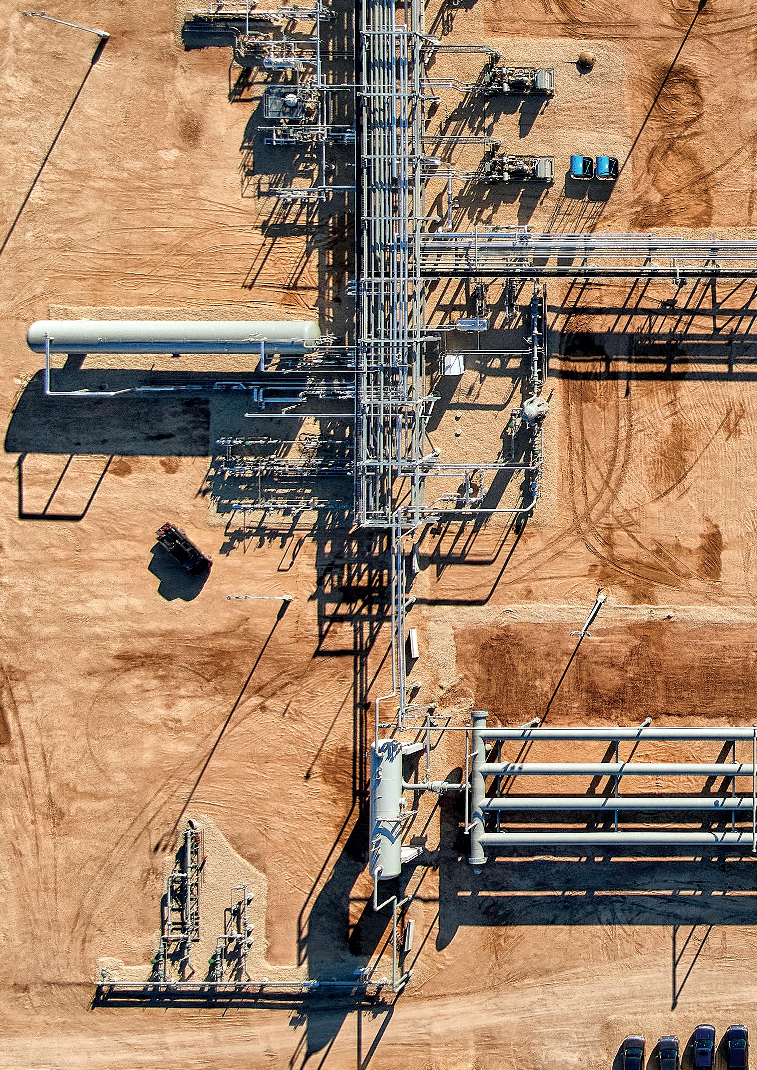
Figure 1. High-level view of a natural gas processing plant using the SureLaunch® multipig launching system and a slug catcher to remove liquids from the gathering pipeline system transporting product from the field.

contrast, slug catchers were said to be ‘inside the fence’ – that is, treated as a bridge between midstream and downstream operations, serving as a link between the pipeline and the processing unit and also as a gatekeeper that prevented liquids from the dry gas flows entering the processing unit.
In practice, then, work on facilities ‘inside the fence’ did not overlap with work on facilities ‘outside the fence.’ Design, procurement, planning, and execution processes for the two systems were handled by different teams, and these teams did not necessarily communicate or coordinate directly with each other.
new way of looking at things
To overcome this mindset, rather than simply outfitting the gathering system with a slug catcher, WeldFit proposed a unique plan that would boost productivity from the pipeline to the plant, something none of the other vendors the operator had contacted had even imagined.
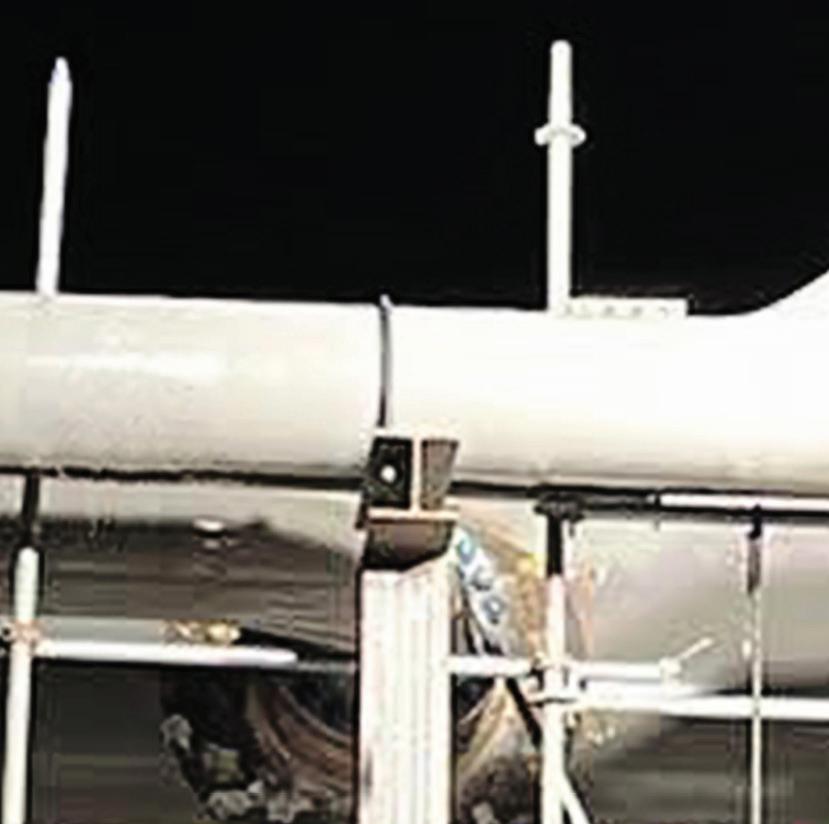
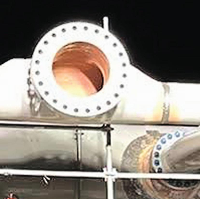
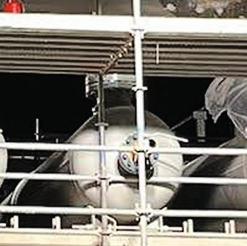
The solution centred around integrating three pieces of equipment: a repurposed storage tank, a new harp-style slug catcher with a 6000 bpd capacity, and a 30 in. SureLaunch® multi-pig launching system, which sets the industry standard for streamlined pigging through automation and would replace the operator’s manual pigging system. Combining multi-pig launching – the SureLaunch system houses and releases up to 10 pigs individually and at predetermined intervals to reduce slug volume – with slug catching operations that would meet the customer’s requirements while also improving the overall efficiency of the pipeline system. More specifically, it would: ) Avoid the potentially catastrophic results of pushing larger slugs through the pipeline, overwhelming downstream facilities.
) Reduce maintenance and operational costs.
) Improve safety and optimise personnel productivity by reducing trips to the launcher and limiting the number of times the launcher door is opened.
) Boost pipeline capacity.
) Reduce emissions by as much as 73%.
Two plans, best choice, right result
To ensure the integrated approach made both economic and practical sense, WeldFit examined two execution options. For each, WeldFit engineers relied on in-house computational fluid dynamics (CFD) modelling to ensure process and flow efficiency.
CFD modelling plays a crucial role in designing and optimising slug catchers by allowing WeldFit engineers to simulate and analyse the complex fluid flow dynamics within these systems.
Planning with clarity: computational fluid dynamics
) Enhances design accuracy: CFD provides a detailed visualisation of fluid flow, including velocity, pressure, and turbulence intensities within the slug catcher. This detailed insight helps engineers optimise designs to ensure efficient separation of gas and liquid phases, minimising the risk of carryover and ensuring the system operates within its intended parameters.
) Enables customisation and flexibility: Every pipeline system has unique characteristics and operational challenges. CFD software enables WeldFit to tailor slug catcher designs to specific operational conditions, accommodating varying slug volumes, flow rates, and pipeline configurations. This customisation ensures maximum performance and extends the equipment’s lifecycle.
) Supports process guarantee: WeldFit can validate the design under various operational scenarios before the slug catcher is even built by using CFD simulations. This prevalidation provides clients with a high level of confidence in the system’s performance and reliability, thus offering a robust process guarantee. It ensures that the equipment will perform as intended in real-world conditions, reducing the risk of operational downtime and maintenance costs.
) Promotes innovation and improvement: CFD allows WeldFit to iteratively refine slug catcher designs based on actual performance data and new research insights. This capability to innovate based on precise, simulation-driven feedback helps WeldFit stay at the forefront of technology in the industry.
The first option entailed installing a SureLaunch Multi-Pig Launching System and a single 6000 bpd new-build harp-style slug catcher. This would cost less from a capital expenditure (CAPEX) standpoint. The second option was more expensive initially but would cost less to operate in the long term. By installing the SureLaunch system with two side-by-side slug catchers, one new and one an existing 2000 bbl storage tank repurposed as a slug catcher at the terminus of the pipeline, would give the operator more flexibility for pigging variability, gas flow,




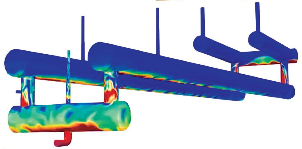
and liquid storage. It would also reduce construction costs: reducing the size of the new slug catcher from 10 000 bpd to 6000 bpd would cut the amount of steel piping required to build it by 400 ft. Best of all, with two slug catchers, the operator could take one down for maintenance or cleaning and still flow 100% gas at all times.
Altogether, with the pipeline being pigged twice a day, this option would result in a 76% reduction in monthly OPEX over five years. It also offered the advantage of bringing the time
needed to recoup capital expenditures – down from nearly 14 months to less than seven months.
With the operator agreeing to move forward with the second approach, WeldFit began planning the installation and implementation, which was completed on time and within budget.
The SureLaunch system enables operators to maintain a consistent and predictable pigging schedule. Its electric drive feed mechanism – controlled by a logic-driven, PLC-based control system – is designed to launch seven to 10 cleaning pigs automatically or one smart pig in manual mode for inline inspection (ILI). Internet based-remote control and solar power are available options. Quick-opening closure options and other design features make launching and receiving pipeline pigs safe and easy.
As for the harp-style slug catcher, its modular design enables streamlined field installation, including skid mounting and custom connections, and facilitates future expansion.
The impact of this project shows, however, that for WeldFit, innovation isn’t just about product design, but project design, as well. WeldFit’s installation of an integrated flow assurance solution combining a SureLaunch Multi-Pig Launching System and a harp-style slug catcher represents a genuinely new approach to the issues of pipeline pigging and liquids handling.
The company has taken the ground-breaking step of recognising that pipeline pigging and liquids handling are inextricably related. It has determined that since the pigs move unwanted liquids through the line to the slug catcher, where they can be diverted and kept separate from the dry gas that then moves further along to a processing facility, they ought

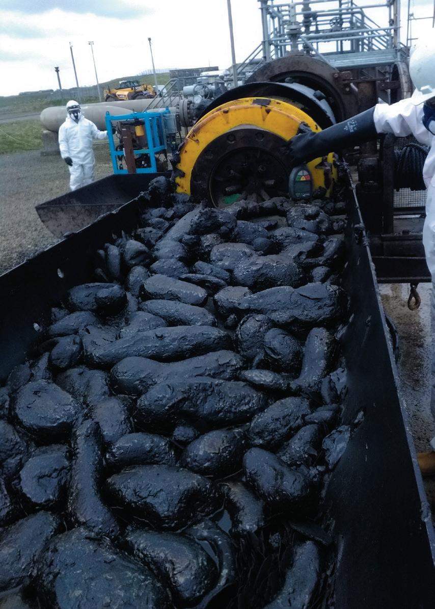
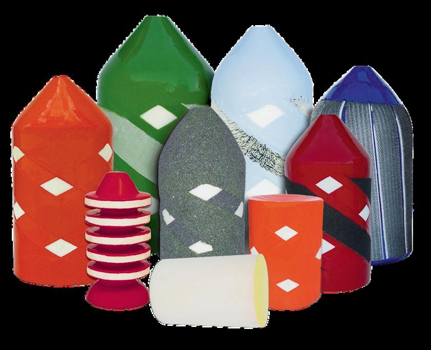
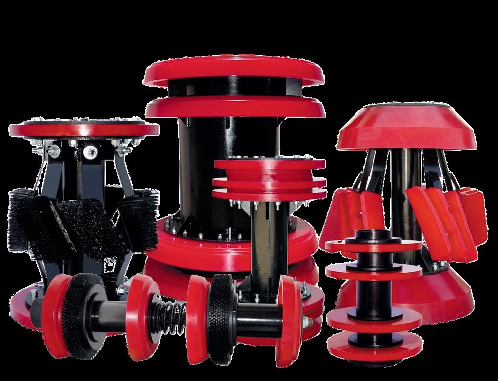
Once a pipeline is in production, debris within the system can be more extreme, with sand or scale or wax deposits. This can require more specialist pigs to be used, where designs are more focused and offer the ability to be adjusted as part of a progressive cleaning programme.
Propipe pigs are designed specifically for each pipeline and offer optimum performance to maintain maximum production pressures and flow.
Standard Pigs - No Bypass

Propipe Pigs with Bypass

Full testing facilities and the Trident pig tracking range are available.


to be used in concert. It also recognises that integrating these two systems will help optimise efficiency and cost by allowing customers to pig more frequently while also right sizing their slug catchers.
These advantages aren’t limited to this project alone.
For example, despite pigging its system six times a day, another Permian Basin natural gas pipeline operator was unable to keep liquids out of the gas volumes flowing to a process facility. By expanding their slug catcher and pairing it with a SureLaunch Multi-Pig Launching System, WeldFit boosted the volume of liquids that could be separated from gas flows from 500 bpd to 3000 bpd. With less liquid remaining in the pipeline, the operator increased the volume of gas flowing through the system.
WeldFit took a similar integrated approach when an operator in New Mexico wanted to build a 3000 bpd slug catcher to reduce the volume of liquids flowing through its natural gas gathering system. By installing a SureLaunch MultiPig Launching System that enabled more frequent pigging of the customer’s pipeline system, WeldFit was able to build a slug catcher with just 50% of the original projected capacity. Increased pigging led to a drop in the total volume of fluid and an increase in the total volume of gas moving through the system at any one time.
What this proves is that WeldFit’s total integration approach can be replicated and scaled to fit gas pipeline systems of different sizes. Making it a multi-purpose solution for multiple challenges.
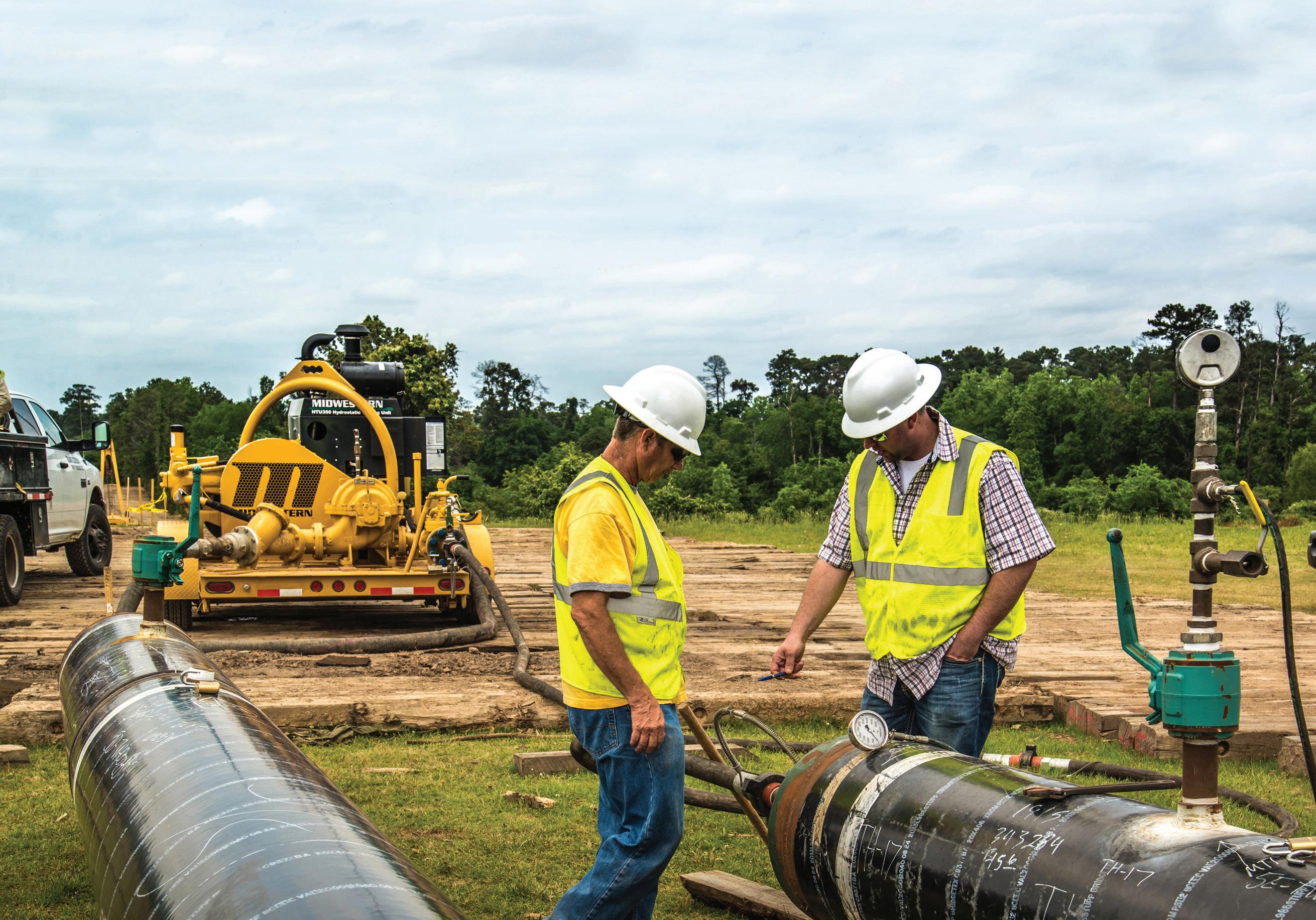
As the premier portable two-in-one Hydrostatic Testing Units in the pipeline industry, Midwestern’s HTU-350/500 automatically fill and test pipelines in one step. These units offer the fastest fill rate based on horsepower input with automatic switchover for filling pipe, pushing pigs and pressure testing.
That’s how Midwestern stands up to the pressure.

TDr. Jennifer Worthen, Emerson, outlines a new scope on emissions monitoring and optimisation for pipeline companies.
he energy industry’s trilemma requires a balanced approach to solving difficult and complex problems. The emphasis is on meeting demands for long-term energy security, equity among stakeholders, and environmental sustainability.
Pipeline operators are mitigating the effects of climate change by transforming systems to bolster safety, lower energy usage, and reduce operational costs or capital expenditures..
Decarbonisation, however, is not just a mandate to the energy industry. It is a shared responsibility across multiple industries. Large energy users are under enormous pressure to serve the needs of the market and investors by tracking and painting a complete, consistent, accurate, reliable, and transparent picture through identifying and quantifying their greenhouse gas emissions.
Pipeline companies have been following the needs related to voluntary reporting practices and their view of new emissions regulations, accelerating as a result of US SEC (Securities and Exchange Commission) Scope 1 and Scope 2 rulemaking and the recent adoption of Securities Act amendments.
The final SEC “Enhancement and Standardization of Climate-Related Disclosures for Investors” rule became effective in March 2024, mandating registrants to provide certain climate-related information in their registration statements and as part of annual reports.
Reducing energy consumption goes hand in hand with commonly shared goals of eliminating waste, cutting indirect Scope 2 emissions, and maximising
profitability. A trend has additionally been identified toward differentiating minimising cost (using a cost-based objective function) and minimising Scope 2 emissions (using an emissionsbased objective function).
Energy security is commonly defined in the context of a nation’s ability to satisfy contemporary energy demands, and maintain the resilience, safety and performance of its energy infrastructure. The tightening of regulatory environments isn’t limited only to what’s happening in the US and Europe. Additional and more comprehensive policy reforms are already being anticipated.
An energy system can align on environmental quality and comply with the regulations, ensuring Scope 2 emissions monitoring and reporting requirements can be met while being proactive about retaining organisational preferences for adaptation.
A practical approach when considering the use of emissions regulations, monitoring, and/or reporting software is to look through each of these lenses, considering the potential of simultaneously accessing and taking advantage of more than one option.
Electricity is a primary power source for the pumps used to propel products such as crude oil and LNG through pipelines and storage facilities. The pipe, pumps, and valves of a liquids pipeline themselves are not a primary Scope 2 factor as they emit hardly any fugitive or vented emissions.
Inventory guidance for the Scope 2 initiative is specifically set forth to standardise how corporations measure emissions from purchased or acquired electricity, steam, heat, and cooling. It covers indirect emissions from generation only, i.e. emissions physically occurring at the facility where energy is generated.
This accounts for emissions from generating energy that is purchased or otherwise brought into the organisational boundary, including from sources that the reporting company owns or controls, and emissions resulting from the generation of electricity the company purchases from a utility provider.
Pumps can be operated by devices such as electric motors powered by hydroelectric or solar, diesel power or gas turbines with station facilities usually constructed every 20 miles to 100 miles along a pipeline’s route, based on characteristics such as type of product being transported and terrain.
According to the GHG Protocol, nearly 40% of global greenhouse gas emissions can be traced to energy generation, and half of that energy is used by industrial or commercial entities. It is within this landscape that companies are being challenged to identify and understand the risks and opportunities associated with emissions from purchased and consumed electricity.
The novel SEC rules, while not seeking to prescribe any particular tools, strategies, or practices concerning climaterelated risks, instead establish a framework for providing material information to inform investors and public stakeholders’ understanding of impacts on a reporting company’s business, results of operations, or financial condition.
In brief, the entire carbon intensity supply chain and GHG management paradigm have been effectively boiled down to individual company’s responsibility to act, with the push toward net-zero emissions targets and carbon footprint reduction.
Pipeline companies are being asked to demonstrate their diligence and reduce energy consumption, and at the same time maintain profitable operations. Better emissions monitoring and reporting are being developed based on customer preferences for meeting all requirements.
Beyond the capital expenditure associated with new pump station development and required maintenance, electricity usage represents a significant price tag. Reducing it often comes to mind as a logical first step.
Developing the necessary infrastructure that can optimise the number and locations of pump stations along pipeline routes can go a long way toward cutting expenditures, as well as emissions. Optimising performance through equipment or control system changes in tandem with software implementation for monitoring or enhancing a pipeline’s overall capabilities is one approach to meeting all technical requirements, complying with laws, and maintaining profitable operations.
The new SEC rules build on reporting frameworks like the GHG Protocol, pointing to the imperativeness of disclosing key features of the contractual instruments that companies use to enable a clear understanding of the market context related to their energy purchases and a meaningful assessment of procurement strategy.
Enterprise engineering employs data analytics to promote peak operating performance, improve efficiency, and minimise this consumption. Cost savings and emissions reduction potential have been realised by turning off units and reducing the number of required pump stations.
One pipeline company reported using engineering software to make notable improvements, reducing electrical load by over 51 000 KWh through active management of a programme focused on avoiding using electricity during peak hours. The same company, with no compromise to product quality, was able to save 1.3 billion KWh of electricity – equivalent to avoiding 707 000 t CO2e – through decreased reliance on the energy usage required to operate pumps.

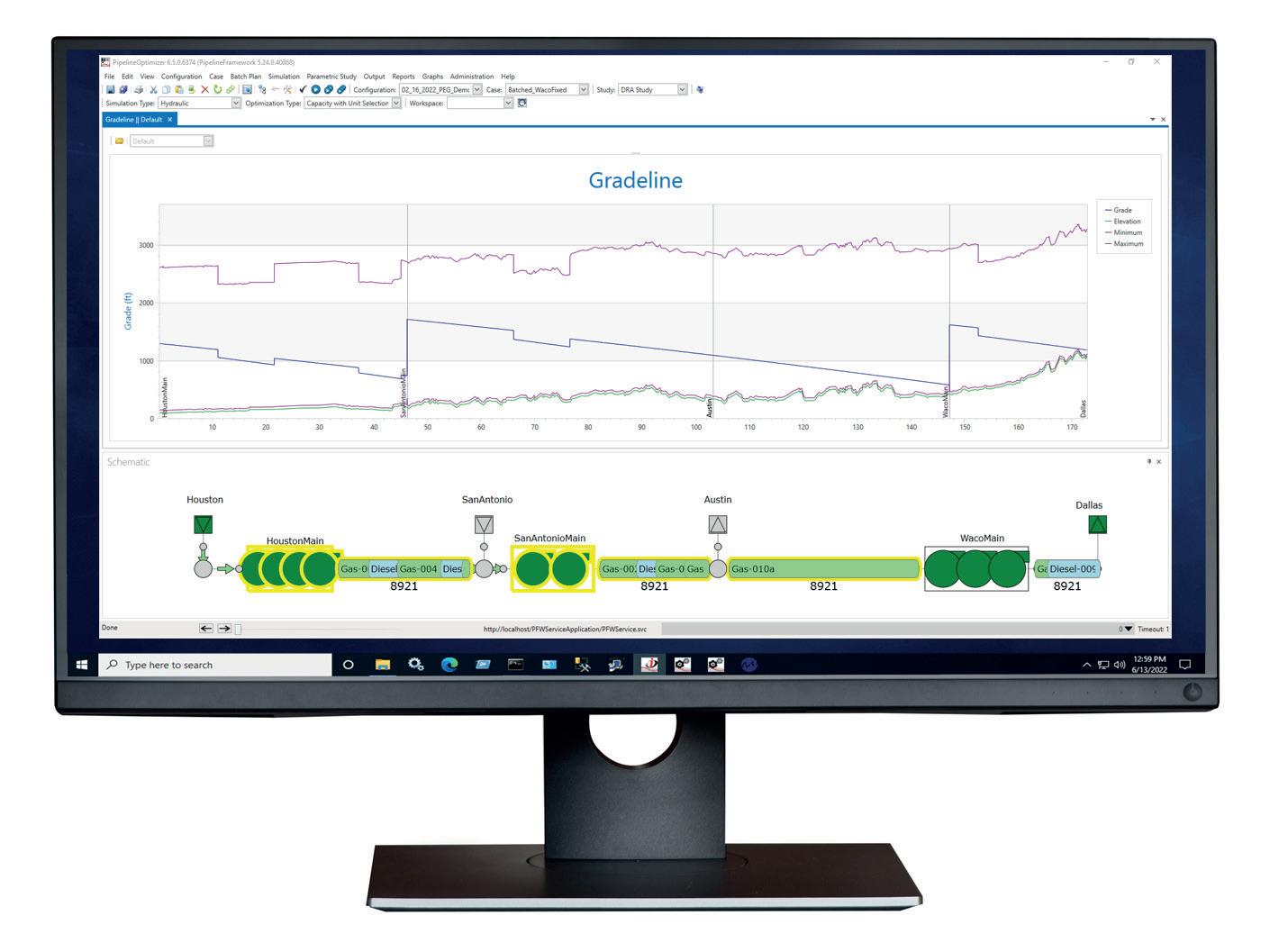
In other words, a direct link has been identified between lowering operational costs and reducing emissions along pipeline routes.
DRAs (drag-reducing agents) are expensive, an additional hard cost of running a pipeline. They are injected to ease the flow of crude oil or refined products, reducing the amount of operational pressure and energy usage required, increasing the throughput of the pipeline, or a combination of the two.
Companies that are making improvements to pump efficiency and optimising the use of DRA additives, are maximising the overall performance and effectiveness of pipeline systems.
Robust software aids in determining the optimal quantity of DRA needed to reduce operational overhead. This starts with looking closely at each pump station and how much energy each unit consumes.
Another pipeline company reported combining DRA technology and engineering software with process optimisation, resulting in optimised product movements, automated DRA and additive injections, and decreased power usage and costs.
The amount of energy consumed during the delivery of their products was reduced by 8%, on a volume basis, from 2018 to 2021. The Scope 2 emissions factor was also reduced by cutting energy usage, through DRA additives that decreased friction between petroleum products and their internal pipeline walls.
When optimising to meet an emission-based objective, more DRA will likely be used to moderate friction and improve the throughput and velocity of transporting products through a pipeline, while keeping movement costs as low as possible. However, this DRA increase is likely to be minimal overall.
The SEC has pegged its Scope 2 initiative, contextualising it as a continuous improvement process. External parties – including customers, investors, regulators, shareholders, and others – are increasingly interested in emissions reductions that are vetted and verifiable through documentation.
To calculate indirect emissions, the GHG Protocol cites the Corporate Standard recommendation, which involves multiplying activity data (MWhs of electricity consumption) by source and supplier-specific emission factors to arrive at the total GHG emissions impact of electricity use.
The US national weighted average CO2 marginal emission rate is used to convert electricity reductions into a measurement of avoided units of carbon dioxide emissions. Calculations are defined by the electricity consumed in kilowatt-hours.
Regulators are emphasising quality criteria for transparently disclosing information about energy purchases and obtaining reliable data sources for measuring emission factors from a market- or location-based metric perspective. To be considered a reliable data source, contractual instruments must meet Scope 2 quality criteria.
Various and different regulatory requirements and contracts, especially when crossing regional and state lines, make the ability to customise each pump to align with any given geographical area’s emissions factor imperative. Moreover, trends can change over time, based on factors outside of a pipeline company’s direct control.
Electricity supplier quotas for renewable energy, in addition to emission policies and regulations, and collective impacts of energy efficiency or voluntary demand for renewables, over time, may each come into play.
Multi-objective mathematics equations and optimisation is notoriously challenging. Flexible software with various modes allows users to toggle and choose between supporting a cost-based objective function or an emissions-based one.
These software enhancements facilitate the monitoring and minimisation of Scope 2 emissions resulting from the generation of electricity at each pump station.
Software data collection can assist with removing the guesswork. Integration of data-driven applications for monitoring and reporting, from a cost savings or emissions reduction point of view, or both, can be made simpler and more effective based on customer preferences.
It has been standard practice to minimise operational cost accumulated from the power usage, fuel-based or electrical, used at pump stations over a specified period of time on a pipeline.
Emerson’s optimisation software calculates an estimate for the carbon footprint of individual pump stations on a pipeline, for a specified period. This estimate allows for an objective study to see what the differences actually look like and provides insights on actual changes to overall energy costs.
It presents a configurable solution and unique resolution, allowing operators to monitor each station, aligning for the appropriate emissions factor based on how electricity is being sourced and used. A multiplier for each station can be set and customised based on how the energy used to operate the pump is generated.
It is noteworthy that meeting operational and business goals, and the potential to streamline objectives, is based largely on what pipeline companies are trying to minimise, keeping in mind both short-term targets and long-term goals.
Traditionally, only one function at a time has been set for optimisation. One imperative for approaching the new low carbon economy is assurances that advanced software solutions are
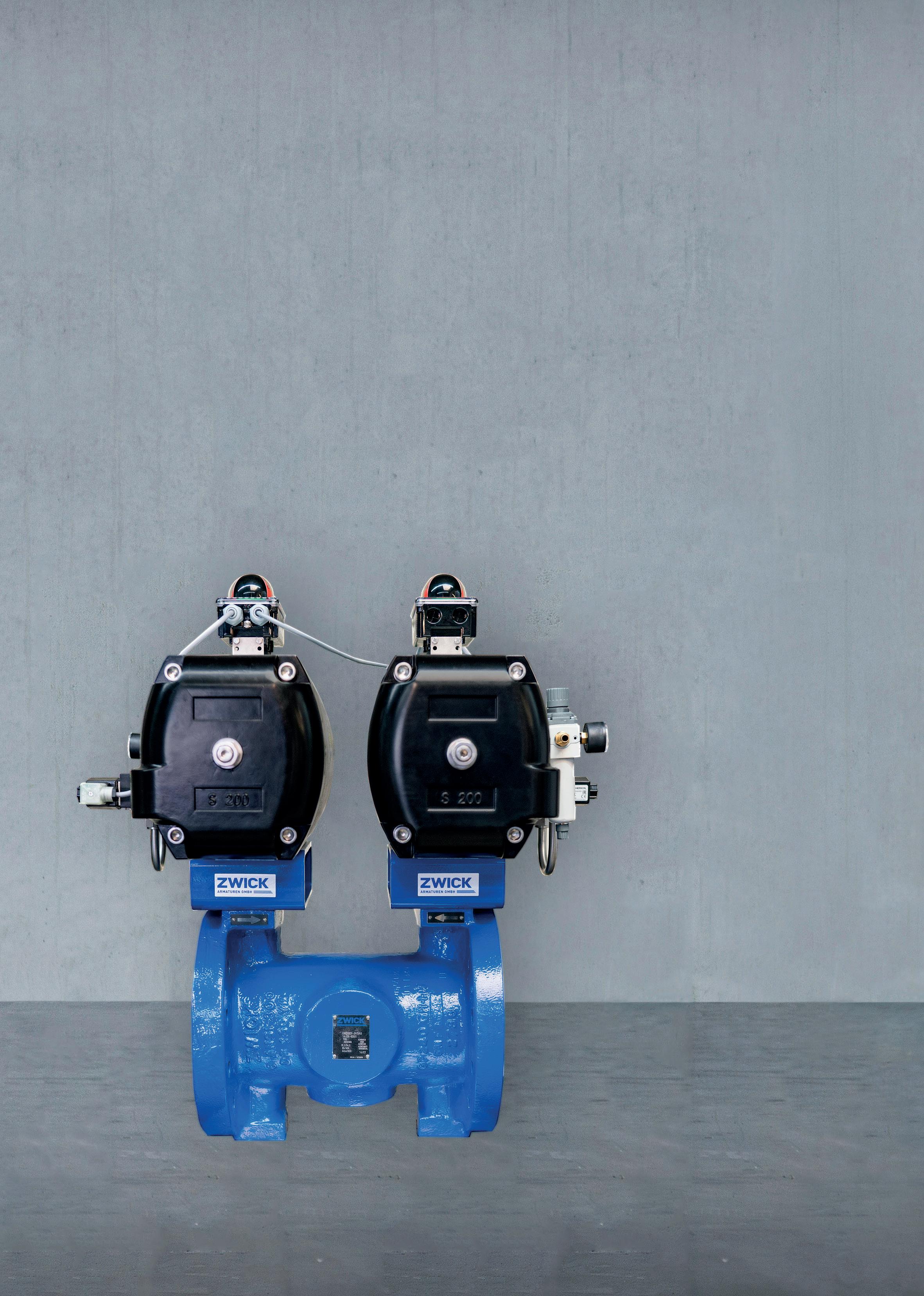
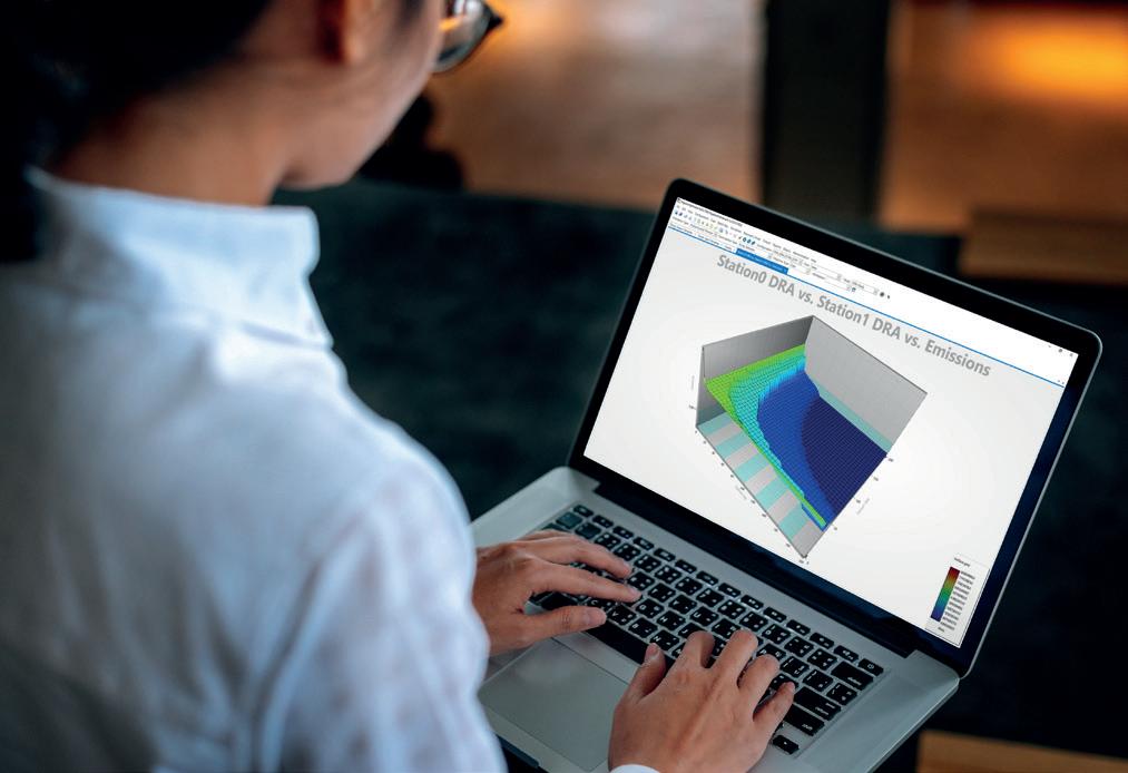
developed and can fully manage and model different scenarios, various compositions of fluids, and a wider mix of energy products, both now and in the future.
A system designed around preferences and integrability – for tasks ranging from leak and rupture detection to batch tracking, modelling and applications for improving flowrate – can be optimised for cost- and emissions-based objective function
duplexity. This may be suitable for satisfying certain regulatory requirements and meeting a range of alternate needs.
According to the GHG Protocol, from a risk and reputation management perspective, “transparent disclosure about a company’s energy procurement and its key attributes in the market-based method can help clarify a company’s strategy and rationale.”
Many pipeline companies that seek methods to clarify their strategy and rationale look into energy conservation and the ‘greening’ of operations, viewing cost savings and power usage energy reduction from a cleaner energy future perspective, discovering added value.
Optimisation is crucial for success in the oil and gas industry for determining risk preferences and uncovering benefits that have the potential to outweigh certain challenges. The ability to know ahead of time what the estimate of value for power costs is, to move additional volume over a specified time, helps decision makers more easily manoeuvre through these complexities.
A key indicator of fewer emissions is a reduction in operational costs. From a competitive standpoint, consistent emissions monitoring and transparent reporting enable more predictable and ongoing comparisons with industry peers.
Accurate monitoring and reporting have been deemed essential, demonstrating a best practice that can differentiate companies across an increasingly cost- and environmentally conscious marketplace.



Ross Dow, Propipe Limited, UK, discusses the critical role of pipeline pig verification testing.
It is now more than ever becoming a requirement to pretest operational pipeline pigs prior to deployment, as in today’s world of pipeline production, the geometric design of pipelines and their inclusive features are pushing pig designs to the limit. Couple this with operational procedures that offer limitations, and you could find yourself with a pigging campaign that is an industry first.
Throughout the lifecycle of a pipeline there are multiple requirements for pigging operations to occur. This can be for pipeline spooling, FCG, dewatering, maintenance/ operational pigging, welding operations and many more applications including bespoke unforeseen events. These operations must be closely assessed to decide if pig verification testing is required.
A pig is a tool utilised before, during and after a pipelines life cycle to prepare/ preserve a pipelines condition for service or future service.
The pipeline specification and operations will define the type of pipeline pig required to complete a scope of work, both of which are closely studied when
building a testing programme. There are multiple factors that come into contention when defining the design of a pig, some of which can be validated with a simple desktop study and some which require further validation through physical trials. Let’s take a dual diameter pig as an example. It is fairly easy now to make a pig that is capable of traversing several changes in diameter, however, designing them to do so whilst maintaining the highest level of performance is not the easiest task without visually seeing the pig perform during trials.
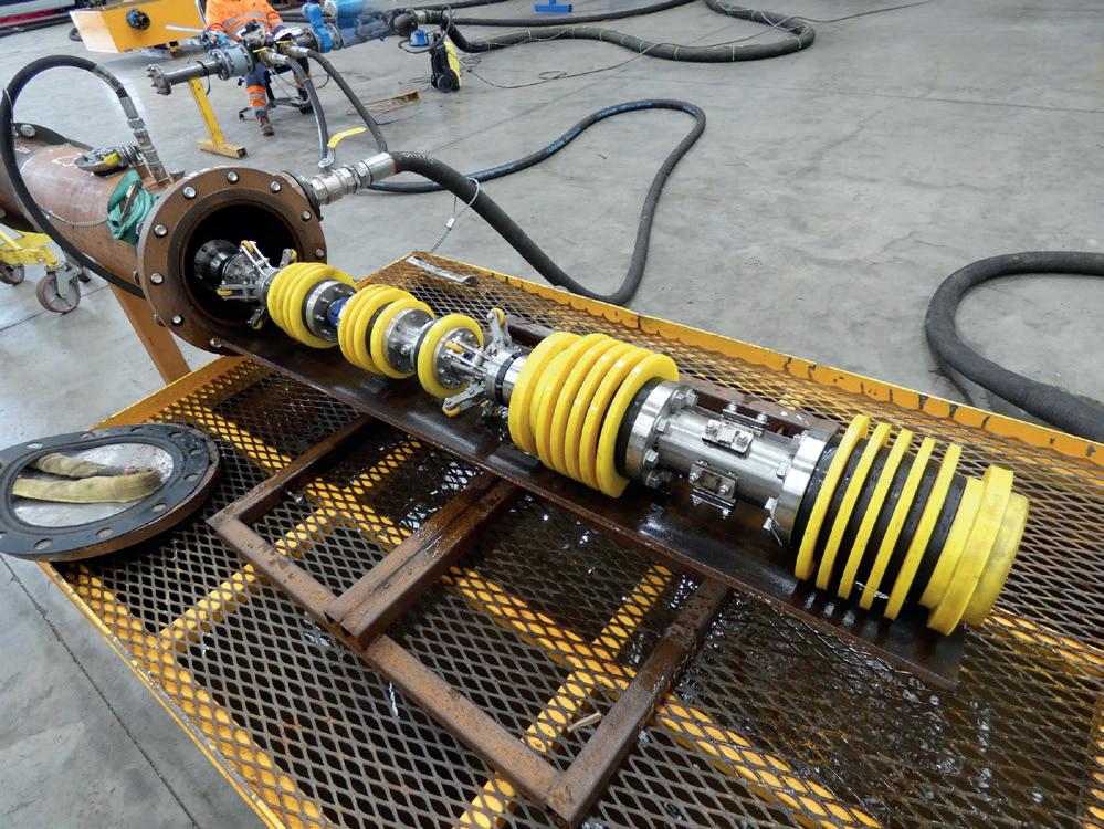
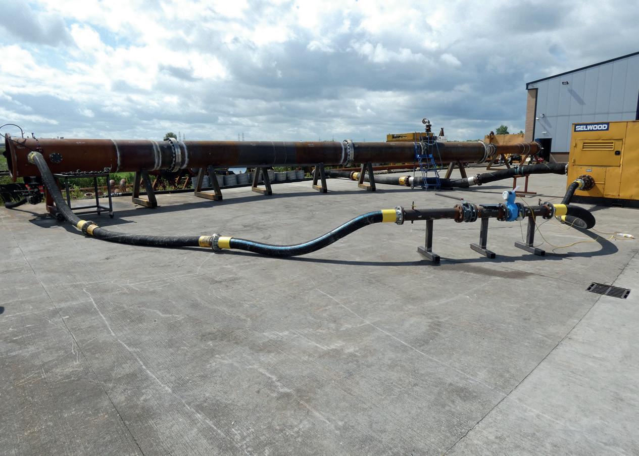
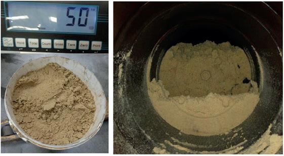
There are many reasons why you would opt to test pipeline pigs before use, some being obvious, is the equipment safe for use? Is it fit for purpose? Some also being inconspicuous, an example of this would be foam pig dynamics through large reductions or expansions. Validation of this provides piece of mind for the operations.
Due to technological advancements in all sectors, pipeline schematics are becoming more common with the inclusion of multiple diameters and a mixture of features that directly affect how the pig reacts throughout a pig run. Confirmation of safe passage and also correct pig design needs to be demonstrated for these circumstances. Pig design can only be taken so far through a desktop study until physical trials need to play a part, as there are many cases where a pig design can look correct within modelling software, but when subject to running conditions, we learn that there is some fine tuning to be done to maximise the pigs efficiency.
Examples of potential risks of running an untested pig: ) Stuck pig within pipeline features.
) Lack of sealing element for a dewatering campaign.
) High running pressures within reduced bore multi diameter pipelines.
) Lack of seal capacity when a pig is required to push another pig.
Large costs can occur if a pig becomes stalled or stuck within a pipeline, depending on the scale of scope, the downtime of a stuck pig could become a multimilliondollar issue, think about vessel downtime, demobilisation/ remobilisation costs etc. These unforeseen circumstances could potentially be avoided for a fraction of the cost if proper pig testing is carried out prior to the operation.
One recent case study was a proving factor to this. Propipe was approached by a client who had to recover an articulated pig from a flexible joint as the pig lost seal, the reason for which was unknown. The pig was required to navigate three different internal diameters within the pipeline structure ranging from 150 mm ID – 165 mm ID, the respective range of diameter being upon entry and exit of the flexible joint feature.
Propipe was awarded the scope to construct a test phase and test rig to understand the failure mode and provide a workable solution. It was found that as the articulated pig spanned the angled flex joint, a number of seals were redundant as they were laying across the ‘windows’ within the flex joint, this meant that all drive pressure was acting on the rear seal and front seal which had no support along with little capacity to drive the pig past the feature. In a scenario where sealing discs lose capacity; the disc flips and flow bypasses the seal. It was by carrying out physical trials that this was uncovered and resolved, giving the customer a workable solution to complete their pigging campaign.
There are multiple factors that need to be considered when designing pig trials, and each one carries its own importance. If there is a major piece of information missed, then it could completely invalidate the trials carried out. The requirements and specifications must be closely studied to both build the correct test rig and test pig.
The pipeline features and pipeline IDs that affect the pig the most need to be replicated as accurately as possible, this can determine how sealing and support elements of the pig transitions throughout the pipeline. It is important to understand that small changes in pipeline specification can affect how a pig will perform.
Test rig materials: using carbon steel constructed test rigs for the majority of applications is suitable to obtain valid results. For the majority of applications, it will provide ‘worst case’ differential pressure data for running the pig and the sealing discs will be subject to higher wear.
There are cases where pipeline material should be matched to offshore specifications. If you are looking at running high friction pigs for spooling purposes, then the pipeline specification and materials used during testing must match the offshore construction. If you are to run a high friction pig within a carbon steel pipe, but operationally it will be running in a stainless lined pipe, two entirely different
Test phases for high friction spooling pigs are unlike any other, as the pig is required to withhold a specific head pressure at the very end of the pigging operation. This means that the full pipeline spooling distance is required to be pigged during testing prior to carrying out the final pressure test. Seal wear, pigging pressure, and hold pressures are monitored throughout the testing to ensure the campaign is
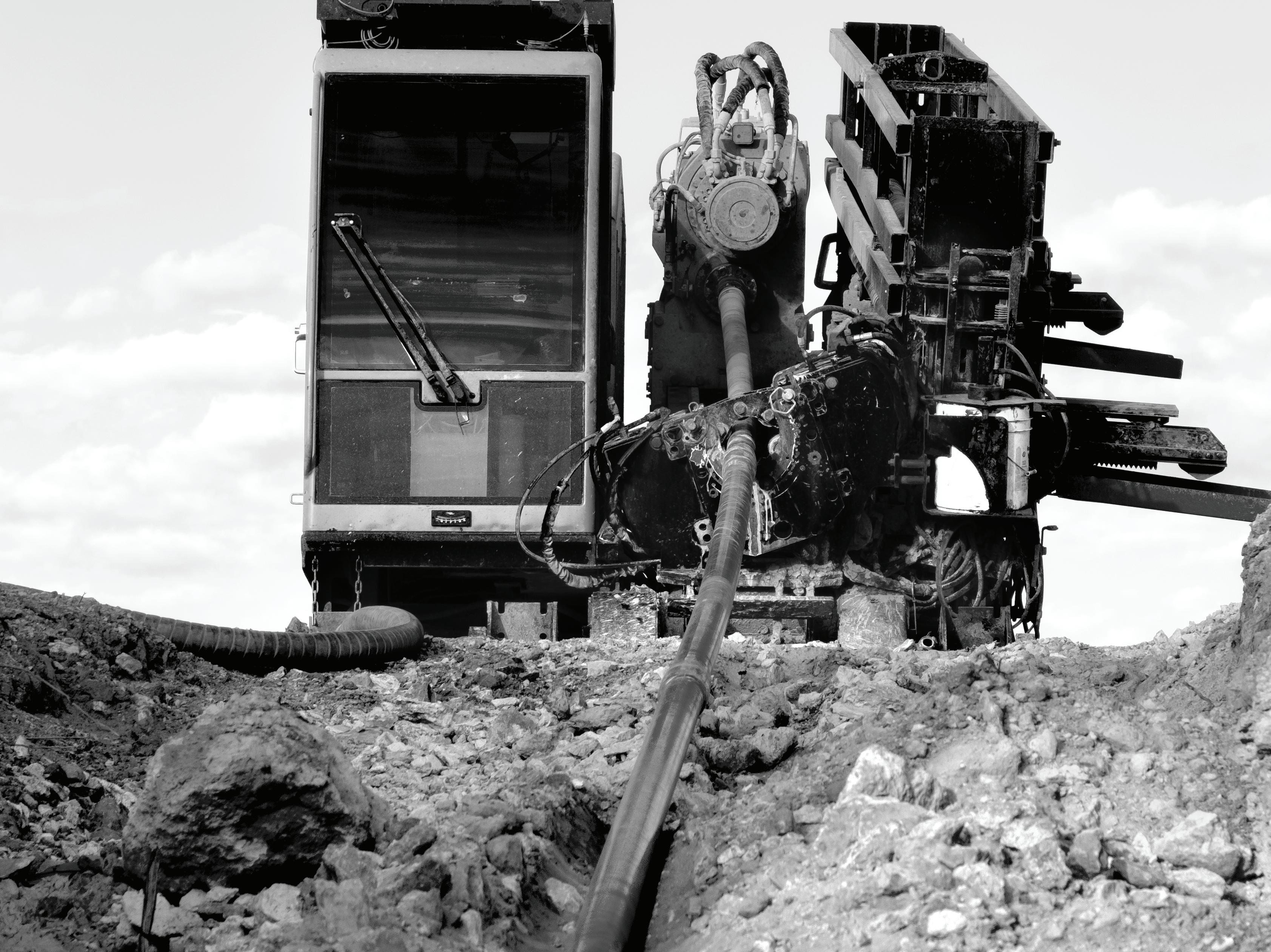
“ See why the D100x140 S3 HDD is still the one crews rely on.
I’ve run that machine for about five years. To me, it’s the most versatile machine there is. It can fit into some pretty tight places and, man, it’s a strong machine. Absolute monster of a machine. It’ll do anything we ever ask it to. Anything from 3,000-ft shots to short 80-ft shots. It’s the one for the job for sure.” – Michael Contreras | West Texas Boring
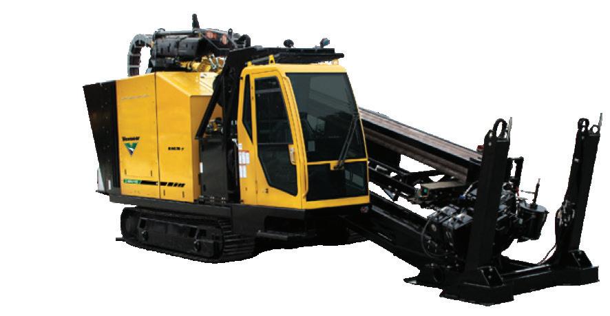



Depending on offshore pigging requirements, testing spools can also be coated with wax, oil and filled with sand/ debris to best simulate offshore conditions.
Propipe recently performed a maintenance pigging test programme where the client wanted a maintenance pig capable of sand removal. The pig had to navigate a small change in internal diameter whilst being able to safely pass 5D bends, an equal wye piece and open check valve. The client also required the maximum pigging pressure to be below a set pressure to ensure their pumping spread didn’t need to be increased in capacity. During the trials multiple PIG
configurations were tested with the inclusion of 50 kg of sand being inserted into the test rig launcher. The pig configuration that could safely pass all features, under the required flow/ pressure limitations, and maintain a high level of performance was qualified for pipeline maintenance Pigging procedure for the following 25 years, with the pig recovering 49 kg of the deposited sand (Figures 3 - 5). The efficiency of a pig can only be demonstrated through physical testing, results obtained would have never been possible through desktop studies or simulation.
Conducting and learning from physical trials
As stated previously, it is important to conduct trials with bespoke and accurate test rigs to gain a valid test result. Trials also need to be as effective as possible by using advanced logging equipment to gain as much data as possible in the time used, this data can then be assessed to understand the flow rates and pressures involved when evaluating the pig’s performance.
A piece of example data can be seen in Figure 6. During this pig run, Propipe carried out a stop start test format to ensure the pig could stall and restart again within all pipeline features. This may be required due to pump shutdowns or any other circumstance that may affect pumping. The data obtained during this test allows for a judgement on successful piggability to be made and also provides significant flow and pressure figures to the customer for the size of spread that may be required for offshore operations.
As well as data recorded through transducers, due to advancements in camera equipment we can also add video cameras to the pigs to get ‘in the pipe’ visuals if closed spool testing is occurring, or there are multiple bends involved. This allows for visuals of bypass to be located.
Having correct data and the ability to evaluate it accurately allows you to have a reactive response to any actions that need carrying out. Utilising the trial results gives you the best opportunity to improve the pig design and functionality if required. This reactivity is what allows for successful test campaigns as detailed in the previous case studies described.
Regular testing yields valuable data that can be used to enhance pig design in the future. Engineers in our field can use the data to identify areas for improvement in future projects. Here at Propipe we also include our trident tracking equipment into testing scopes, so it doesn’t only provide valuable pig data, but also allows us to optimise the capabilities of our detection software and hardware. Pig testing for us is a continuous feedback process that drives innovation and allows the exploration of new technologies.
As old and new heads collaborate in the pipeline industry, testing advances knowledge sharing between operators and engineers from across the industry. Collaborative efforts allow for industry knowledge to be passed on to the next generation of pipeline engineers, and will hopefully allow for the boundaries to be pushed and explored with pigging in focus.

At T.D. Williamson (TDW), we’ve been perfecting pipeline pigging for decades, helping businesses boost production, keep assets running longer, and cut down on operational risks. TDW aims to make things more cost-effective and efficient for operators. Our Quick-Ship Pigs programme in the Western Hemisphere offers next-day shipping for pigging solutions that cover over 80% of field applications, with a primary focus on progressive pigging products.
Our D2000 quick-actuating closure is a standout in the industry. It’s designed to ensure technician safety, while drastically reducing emissions and safeguarding the environment. Plus, with our ProSeries™ Advantage, the D2000 isn’t just meeting more specs and industry standards – it’s also available faster than ever, ensuring you get top-notch reliability and speed when operators need it most. TDW Pigging remains committed to supporting operators on the journey to optimise their pipelines and ensure continuous product flow.
The recent expansion of a 145 km (90 miles) multi-phase pipeline system presented several challenges when the operator added three new sections to the main pipeline and two branches along the gathering route. This expansion increased the total length of the pipeline system to 354 km (220 miles). Initial pigging operations aimed to manage the load, displace liquids, and recover condensates from the original segment, but they were not optimised for the increased production of liquids, back pressure,
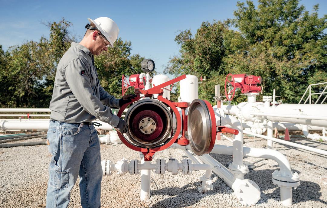
1. The D2000 quick-actuating closure combines operator safety with ease of operation. Fewer parts than other closures make it easy to clean, easy to maintain, and reduce the risk of failure. It’s standardised to fit a wider range of sizes, applications, technical specifications and requirements to help assure safe, compliant performance.
or the capacity of the receiving equipment. These oversight issues led to recurring two day shutdowns at downstream plants and system-wide disruptions, flooding at plants and increased wellhead pressure to 76 bar (1100 psig), thereby reducing well delivery capabilities.
To address these operational setbacks, the operator enlisted the expertise of TDW. TDW tailored a conservative pigging strategy combined with an automated pigging operation, all executable with the existing workforce.
The revised approach, implemented over a 30 day period, yielded significant improvements. The pipeline system operated at full potential with no unscheduled halts, maintained stable flow conditions, reduced liquid buildup and back pressure, and decreased wellhead pressure to 72 bar (1050 psig), boosting gas production by 5 million ft3/d from the wellheads. Additionally, condensate recovery rose from 1800 bpd to over 2100 bpd without incurring extra production costs. The operation of receiving equipment became more predictable, corrosion potential was minimised, and the system was kept primed for smart tool inspections with minimal cleaning.
Furthermore, traps were maintained in optimal condition, and regular maintenance was applied as needed. A proper pig inventory was upheld alongside predictable pigging data collection. As the pipeline system evolves and field conditions vary, continued enhancements in maintenance pigging will be crucial for maintaining efficiency, preserving operational value, and minimising long-term complications such as corrosion.
2. With decades of experience cleaning pipelines all over the world, TDW can recommend the optimal pigging equipment and schedule for your specific pipeline – including progressive pigging programmes to overcome reduced flow and maximise throughput.
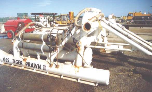
World’s
Above and below - Indonesian Buaya Besar Barge 1.2 m to 20 m depth.
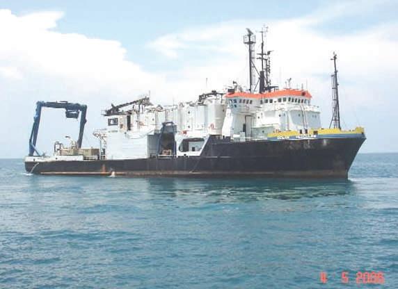
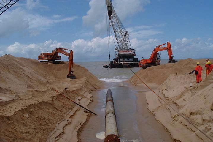
Post Trenching in rough swells off Brazil.
Above and below—Ultra shallow water system 0.6 m to 3 m depth.
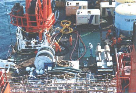
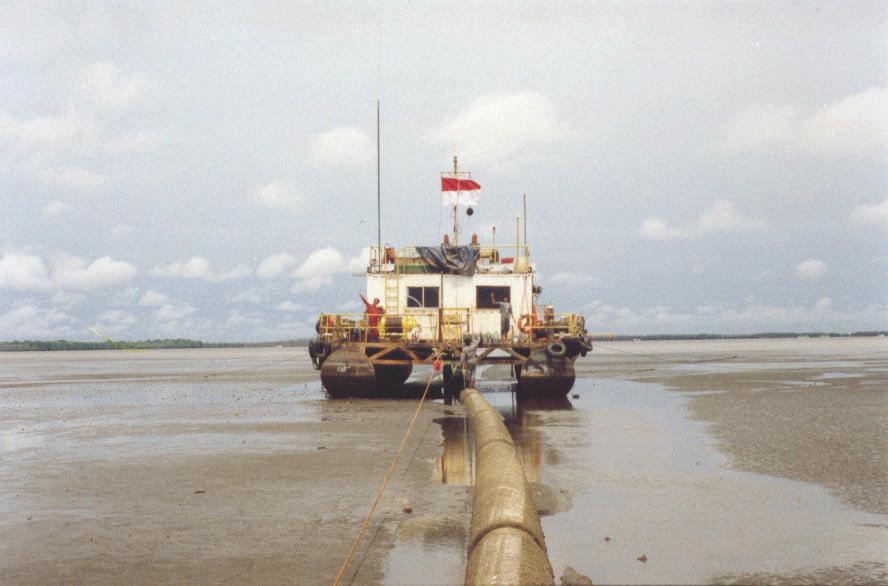
Post Trenching in rough swells off Brazil.
Post Trenching in rough swells off Brazil.
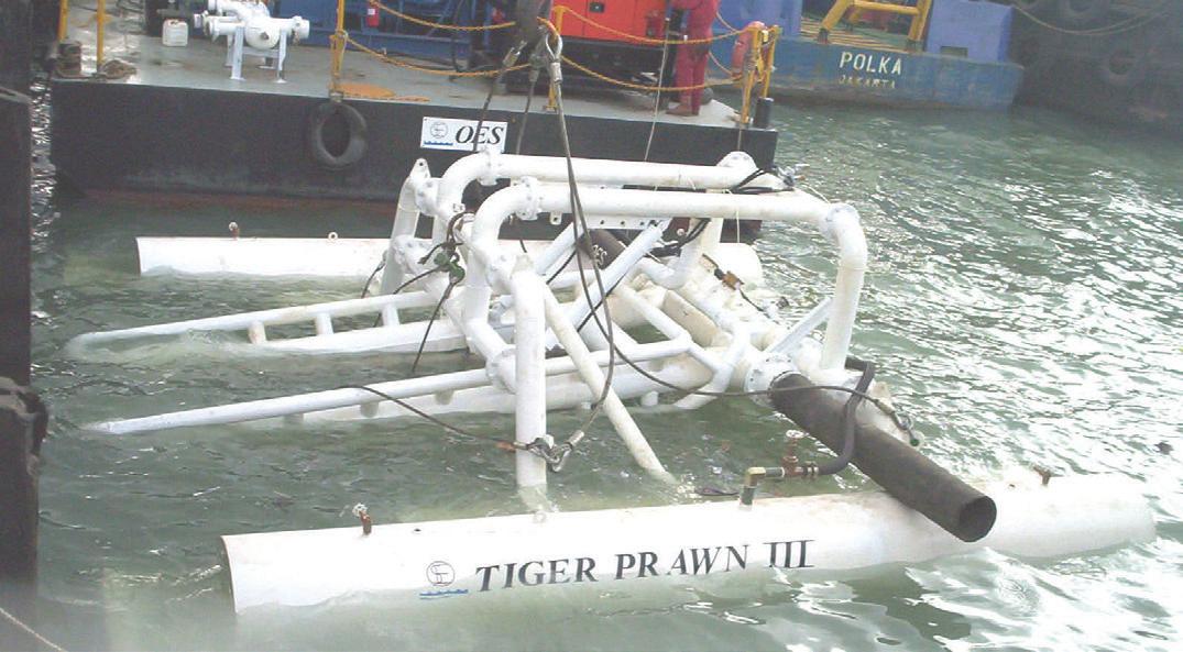
Above and below - Indonesian Buaya Besar Barge 1.2 m to 20 m depth.
Above and below—Ultra shallow water system 0.6 m to 3 m depth.

Above and below - Indonesian Buaya Besar Above and below—Ultra shal system 0.6 m to 3 m depth.
Above and below - Indonesian Buaya Besar Above and below—Ultra shallow water system 0.6 m to 3 m depth.
Above and below - Indonesian Buaya Besar Above and below—Ultra shal system 0.6 m to 3 m depth. Diverless Systems
OES World Leader in Subsea Pipeline Trenching Is For Sale (all assets tangible and proprietary intangible) Track Record since 1992 includes the successful trenching of over 250 pipelines and cables including the following world’s firsts:
• Largest Pipeline 54 inch 1995 India
DP vessels
First Trenching by Dynamic Positioned Vessel 1992 New Zealand
• Trenching in largest Seas 28 ft 1992 New Zealand
Trenching Hardest Soils with proprietary high pressure system 150 kpa shear strength Thailand 1993
working off DP vessels
vessels
• First and only Post Rock Trencher ‘Tiger Shark’ 1994 to 2008
Key Largo, USA
Trenching Deepest Pipelines 400 meters 1999 Bass Strait
working off DP vessels
Trenching Deepest trench 7 meters 2000 Indonesia
• Trenching in strongest water current 11 knots China 2004
Trenching Stress Relieving of Directional drilled pipelines by others Australia 2004
• Trenching Live Gas Pipelines Indonesia 2006
Busan, Korea Singapore
Trenching roughest shore approach with pumps on beach Ghana, Africa 2018
Rio De Janeiro, Brazil
Seychelles Islands .
Balikpapan, Indonesia
• Also laid 7 kilometers of 150 NS 110,000 Volt cables including directional drilling shore approach through rock cliffs
• Salvaged six projects where pre dredging, directional drilling and jet sleds failed
Melbourne, Australia Corporate Headquarters
Equipment Includes: 45 20 ft sea freight containers with 8 x 1600 hp 350 psi pumps, 2 x 1000 psi booster pumps, 3 hydraulic hose reels with 90 to 120 meters of 4 x 4 inch hose, interconnecting piping and suction strainers, 6 x subsea pipeline lead keel type jet machines for 6 inch to 52 inch pipelines, Arabian Leopard, White Jaquar, Bengal Tiger, Tasmanian Tiger, and Sumantran Tiger, 1 Tiger Shark cuts 600 mm deep trench per pass x 1200 mm wide in 30 mpa ucs rock, 2 cable trenchers that simultaneously backfill to 1.5/3 meters cover. An eight point mooring system 20 tonne, 20 tonne heave compensator, 3 Hydraulic power packs including 1 300 HP for tiger Shark, 1 Tiger Shark Hose reel with 2 x 500 meters of 5000 psi hydraulic hose and a 10 tonne clump weight and deployment system. A 10 tonne hydraulic cable tensioner.

Company Value 1995 to 2014 $100 million. Sell now $5 million or best offer. Ask for photos, specs, container lists and completed project references.
World Pipelines speaks with David Hunter, Segment Development Manager for CUI/ High Heat & Insulation, Hempel, about the paint and coatings company’s entrance to the insulation coatings market, discussing new insulation solutions that prevent Corrosion Under Insulation (CUI).

World Pipelines: Could you start out by telling us a little bit about the inspiration and innovation behind Hempatherm?
David Hunter: Absolutely. Insulation coatings are not new. In fact, variations have been on the market for over 25 years. Thermal Insulation Coatings’ (TICs) ability to
mitigate CUI, their thermal performance stability, and long, maintenance-free service lives are well understood. These features are even recognised by API. The challenge with the technology is that the majority of the competing TICs cannot be applied thickly enough to rival the performance of conventional mechanical insulation
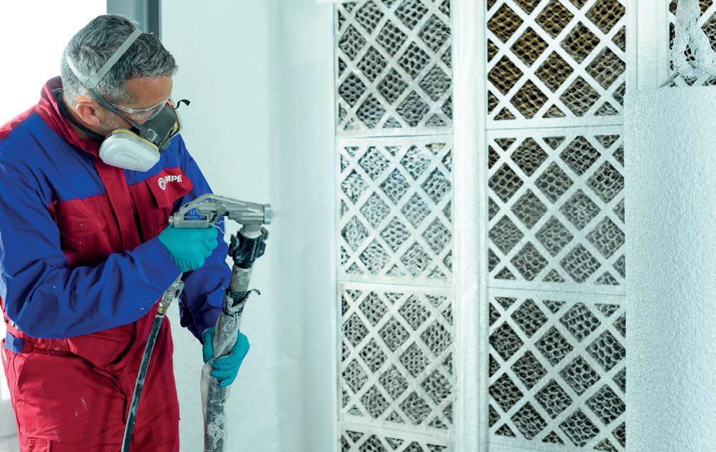
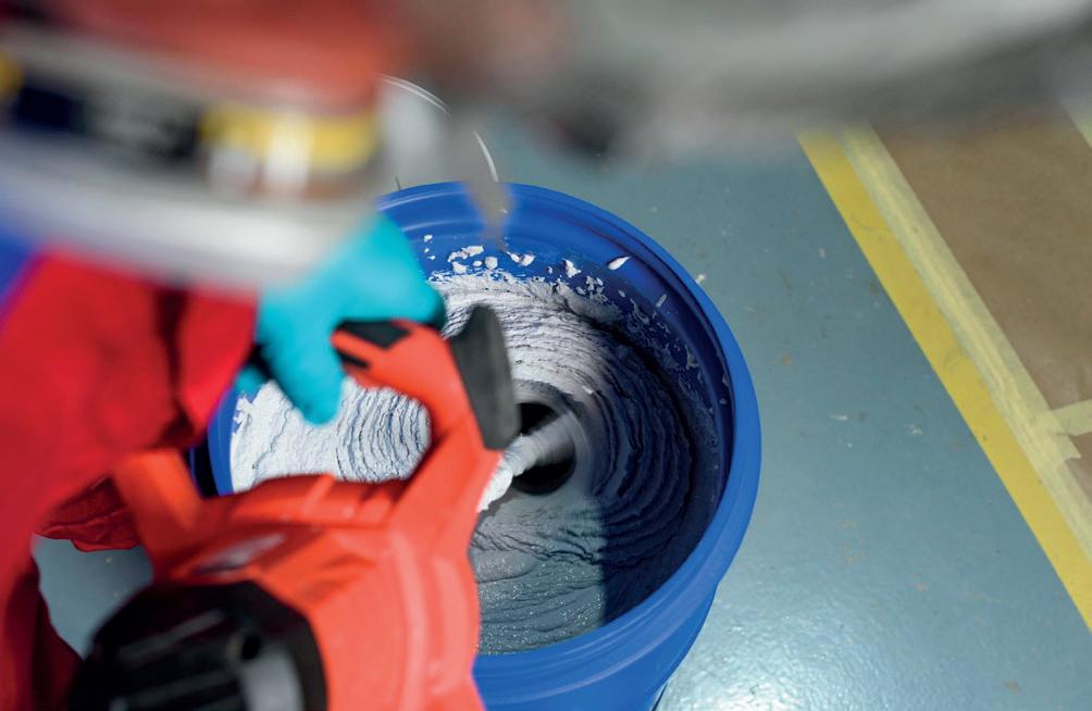
alternatives. Hempatherm addresses that problem, making the addressable market much larger for TICs - and Hempatherm in particular.
The second part is that we listened to our customers, who are all interested in more sustainable operations. A typical process for monitoring CUI at facilities is to remove (and dispose of) existing mechanical insulation, inspect the surfaces, and then replace them. This obviously creates a lot of waste that goes straight to landfill, and this amount of waste has been identified as a top contributor to the overall waste stream of a facility. TICs can help in solving this problem.
Hempatherm offers a comprehensive suite of features, designed to meet the diverse needs of our customers, but also of our applicators working in the field. Notably, it provides high film build per coat, which reduces application labour costs. The products are non-hazardous, and zero VOC, which minimises worker exposure to hazardous solvents and chemicals. The Hempatherm system is non-flammable, which means that it can be applied on hot surfaces up to 150°C (300°F), without shutting down operations.
When it comes to CUI, Hempatherm’s operation range almost exactly covers the temperature range that is characterised by CUI, from -25°C up to 177°C (350°F). Additionally, the system can be used for
personal protection from burns, while also effectively preventing solar heat gain, thereby contributing to energy conservation.
World Pipelines: What sets Hempatherm apart from traditional mechanical insulation systems?
David Hunter: Great question. What truly distinguishes Hempatherm are two things: Hempatherm’s ability to stop CUI and its long-term durability. All traditional mechanical insulation systems have seams that allow water to enter, thereby reducing the insulation’s effectiveness and thermal performance – and even if the traditional insulation is hydrophobic, water can still get behind it. Hempatherm is seamless, hydrophobic, and bonded directly to the substrate, which means that the thermal performance stays constant for Hempatherm’s service life, while simultaneously preventing CUI.
Secondly, traditional mechanical insulation uses a jacket as its primary weather barrier. The jacket is most often made out of thin metal, which is not very impact resistant. It cannot be stepped or walked on, and damage to the jacketing is often characterised as a primary reason for water ingress. The Hempatherm system has a very high impact resistance and a 15 year weathering durability testing, with no water ingress, even if the primer is damaged during installation. The product is designed for atmospheric service, but was also shown to handle intermittent immersion in water.
World Pipelines: You also mention how the Hempatherm system contributes to energy conservation and operational efficiency. Can you tell us more about that?
David Hunter: Yes, that’s true; Hempatherm is engineered with energy conservation in mind. The system is powered by aerogel technology, which gives it a low thermal conductivity, making it a good insulator, coupled with a low permeability acrylic resin. Hempatherm does not hold water to any significant degree, so the thermal conductivity is not compromised, even in intermittent immersion. If you stop water ingress, you can stop CUI, and thereby improve the safe operation of any facility, and any costs of dealing with leaks. Ultimately, this promotes energy efficiency and enhances overall operational performance.
World Pipelines: What do you envision for the future of insulation coatings technology?
David Hunter: As industries continue to prioritise efficiency and sustainability, the demand for advanced insulation solutions will only grow. We foresee insulation coatings technology playing a pivotal role in this evolution, offering not only enhanced performance, but also greater cost competitiveness and environmental sustainability. With innovations like Hempatherm leading the way, the future of insulation coatings technology looks promising indeed.

Philip Roscoe, N’GENIUS Materials Technology, compares the materials, namely nickel alloys and stainless steel, best used to ensure corrosion resistance, cost-effectiveness and mechanical strength of pipes.
educing carbon emissions is the only way to meet the UK’s 2050 net-zero target and renewable energy sources are fundamental for achieving it. The country’s energy production from wind, solar and hydro increased by more than 2% in 2023. But to date these renewable technologies still contribute less primary energy than fossil fuels and government forecasts suggest that – at least for the time being –oil and gas will remain an important part of our energy mix as we transition to become climate-neutral.
However, despite UK oil and gas resources remaining at a significant level, further production in the future will present major challenges. As more and more oil and gas reserves in regions such as the North Sea reach maturity, exploration companies are forced to drill deeper and in harsher conditions. And as oil well depths become deeper, the temperature of the process media and the pressure required to extract it increase accordingly. In many instances, that temperature can reach more than 150°C.
High-pressure, high-temperature (HPHT) wells often contain contaminants including chlorides, hydrogen sulphide (H2S), CO2

and other constituents. Add the presence of seawater and you have some of most challenging conditions in oil and gas exploration.
These subsea environments pose serious technical questions to engineers especially when it comes to material selection. When faced with these extreme scenarios, engineering designers would typically specify nickel alloys such as Alloy 625.
Originally developed in the 1950s as a solution for steam-line piping, this year marks the 60th anniversary of Alloy 625 being patented – a UK patent in April 1964 was followed by a US patent granted in December of that year. Now it is often the default choice of material for oil and gas applications which are exposed to extremely corrosive conditions.
In addition to its corrosion resistance, other properties such as strength, toughness and performance at elevated temperatures make Alloy 625 suitable for a variety of applications within the oil and gas industry including piping, tubing and other components.
Such is its versatility, the grade has also been widely adopted across a diverse range of other sectors including petrochemicals

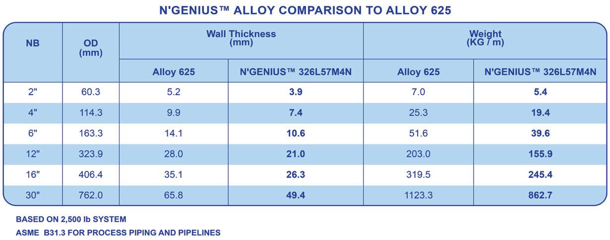
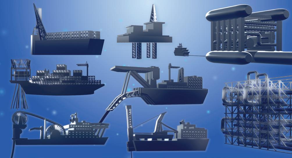
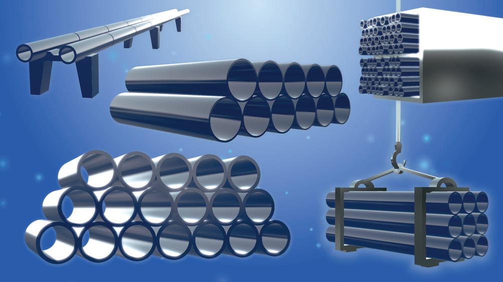
and aerospace, to solve a variety of design and application problems. It’s creep resistance properties make the material particularly suitable for use in jet engine components.
With aerospace firms in the US procuring large volumes of the material, this high demand can inadvertently cause supply chain issues and long lead times in other critical industries including oil and gas. Then there’s the elephant in the room – the price.
With a nickel content of more than 58% and molybdenum at around 9%, Alloy 625 is a grade which is both costly to produce and specify on a project. The high alloy content also makes it particularly susceptible to price volatility and alloy surcharge.
Despite this higher upfront cost, nickel alloys can still be seen as a strategic investment for oil and gas projects. Whilst the initial expenditure would be significantly higher compared to super duplex or a conventional 6Mo stainless steel, its superior corrosion resistance could reduce the amount of maintenance and downtime required over time, contributing to overall cost savings throughout the lifespan of the project.
Nickel alloys have become a popular choice in the industry over many decades. Although just as the demand for high-performance materials such as Alloy 625 has increased, so has the pressure on engineers to reduce capital expenditure. Sudden changes in the price of these materials can have a severe impact on the CapEx of a project, encouraging the adoption of alternative materials which can perform as good, if not better than Alloy 625 but at a more stable and cost-effective price.
These are just some of the advantages that the N’GENIUS Series of High Strength Austenitic Stainless Steels provides.
It is a complete ‘family’ of patented materials designed to significantly outperform conventional austenitic stainless steels from the 300 Series and offer a better value alternative compared to many of the more expensive nickel alloys and high-alloy stainless steels.
With exceptional strength and corrosion resistance combined with excellent toughness and ductility at ambient, sub-zero and cryogenic temperatures, the N’GENIUS Series represents the ideal solution for many of the issues encountered during the material selection process in pipeline, piping systems and the many different components in the oil and gas industry.
One grade from the N’GENIUS Series that is particularly suited to this challenge is 326L57M4N. With a minimum nickel content of 19% and molybdenum of typically 6% and more than 0.4% nitrogen, it’s a material which provides economic and strategic advantages over Alloy 625. Not only is it less expensive to produce, the significantly lower alloy content in N’GENIUS 326L57M4N ensures the cost will remain more stable when the price of alloying elements change, presenting an attractive option for a project finance team. But most importantly, its mechanical properties and corrosion resistance are even greater, providing a high quality material for engineers to design with and specify.
As previously highlighted, for decades the oil and gas industry has utilised Alloy 625 for its resistance to the corrosive effects of seawater, sour gas and other corrosive process media. Its performance against crevice corrosion, pitting corrosion and stress corrosion cracking makes it a suitable material for pipes and tubing. Although the benefits of this grade come at a high price.
By comparison, N’GENIUS 326L57M4N possesses a significantly reduced alloy content but has superior corrosion resistance, giving equipment an even longer service-life than Alloy 625, only in a more cost-effective way.
With oil and gas systems needing to become more durable and contain high pressure, the demand for new high-performance

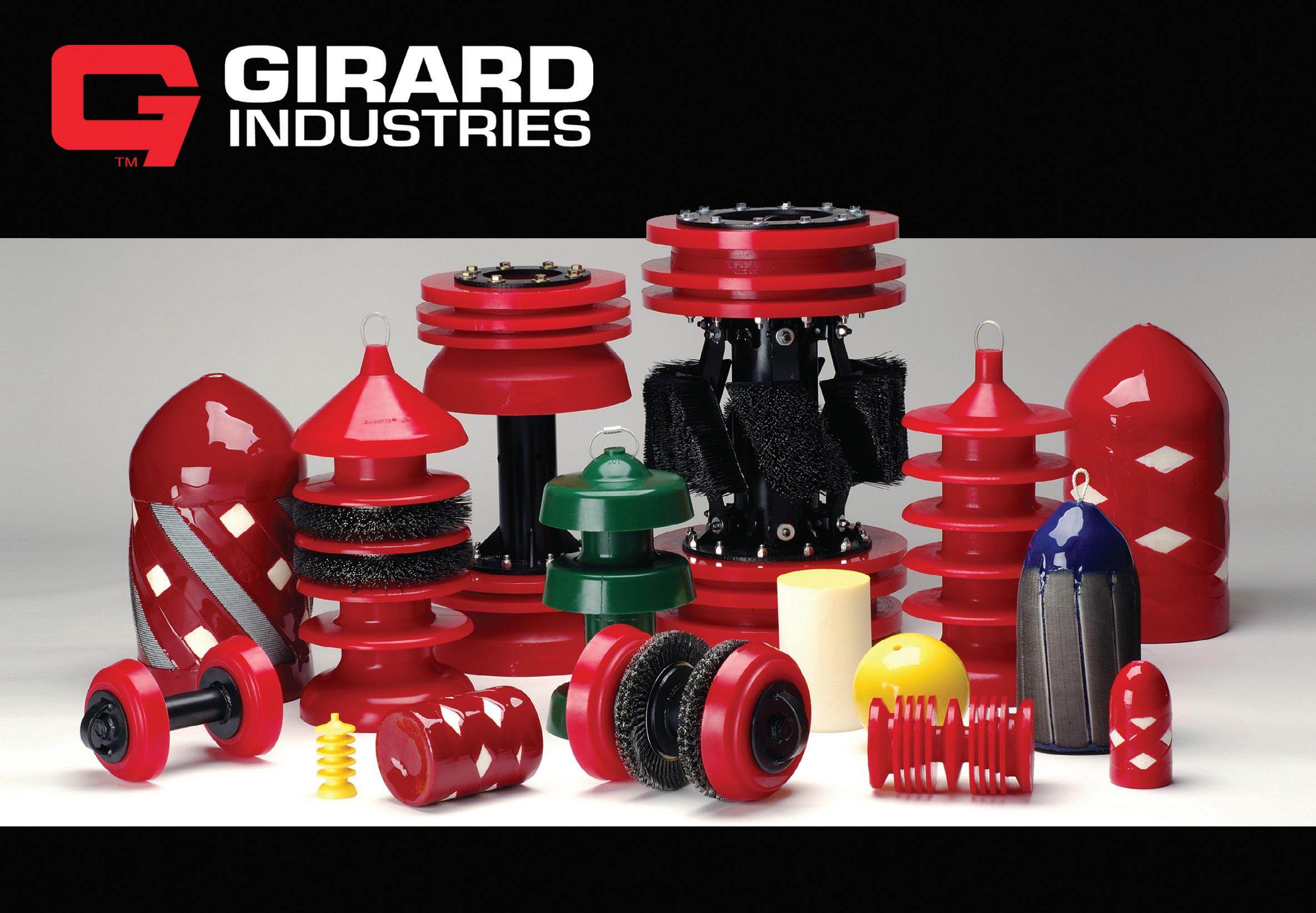

pipeline and piping materials continues to grow. Stainless steels with high strength can provide distinct advantages over nickel alloys and N’GENIUS 326L57M4N is a prime candidate to meet this requirement, possessing even higher mechanical strength properties than Alloy 625.
Combined with its excellent ductility and toughness, the mechanical strength of N’GENIUS 326L57M4N allows offshore pipelines to be installed using various installation methods including S-lay, J-lay, Reel-lay and subsea Bundles installation techniques.
Another benefit of its improved mechanical properties is that products made using N’GENIUS 326L57M4N can be designed with a reduced wall thickness compared to Alloy 625, giving engineers the opportunity to make significant weight savings of more than 23% on projects. For example, when using the design code AMSE B31.3 for Process Piping on a 10 km long, 30 in. diameter, 2500 lbs class pipeline system, N’GENIUS 326L57M4N could deliver a weight saving of approximately 740 t compared to the same system if it was specified in Alloy 625. That weight saving becomes even more significant with larger diameter pipes. A 10 km, 30 in. diameter, 2500 lbs class pipeline system could save approximatley 2600 t if N’GENIUS 326L57M4N was utilised instead of Alloy 625.
These weight savings will be particularly beneficial for subsea and offshore structures, where systems have a tendency to be heavy and difficult to handle. By specifying products in N’GENIUS 326L57M4N, oil and gas systems would require less material and overall structures could become lighter, making the transportation, lifting and installation easier. This would also further reduce construction and project costs and contribute to lowering carbon emissions.
The N’GENIUS Series, which is patented in 30 countries globally, can be manufactured in a vast array of wrought and cast products and equipment for oil and gas production systems. Perfectly suited to seamless and welded line pipe and Oil Country Tubular Goods (OCTG) casing and tubing, N’GENIUS will address the need for a wider selection of corrosion resistant alloys for all types of onshore and offshore projects including those in shallow, deep and ultradeep water environments.
European-based stainless steel producers are conducting Manufacturing Procedure Qualification Tests with a view to providing grades from the N’GENIUS Series, including 326L57M4N in various product forms.
N’GENIUS Materials Technology has also recently signed a sales and distribution agreement with UK-based stainless steel manufacturer and stockist, Project Pipeline Supply (PPS), which provides pipes, fittings, flanges, components and specialist equipment to industries including the offshore oil and gas, process and renewables. This agreement allows PPS to offer customers total packages of products made from the N’GENIUS Series, fulfilling a key stage in the supply chain for major oil and
projects around the world.
The industry is a stronghold for nickel alloys but the superior corrosion resistance, higher mechanical strength and costeffectiveness of N’GENIUS 326L57M4N gives Alloy 625 a new challenger to contend with.
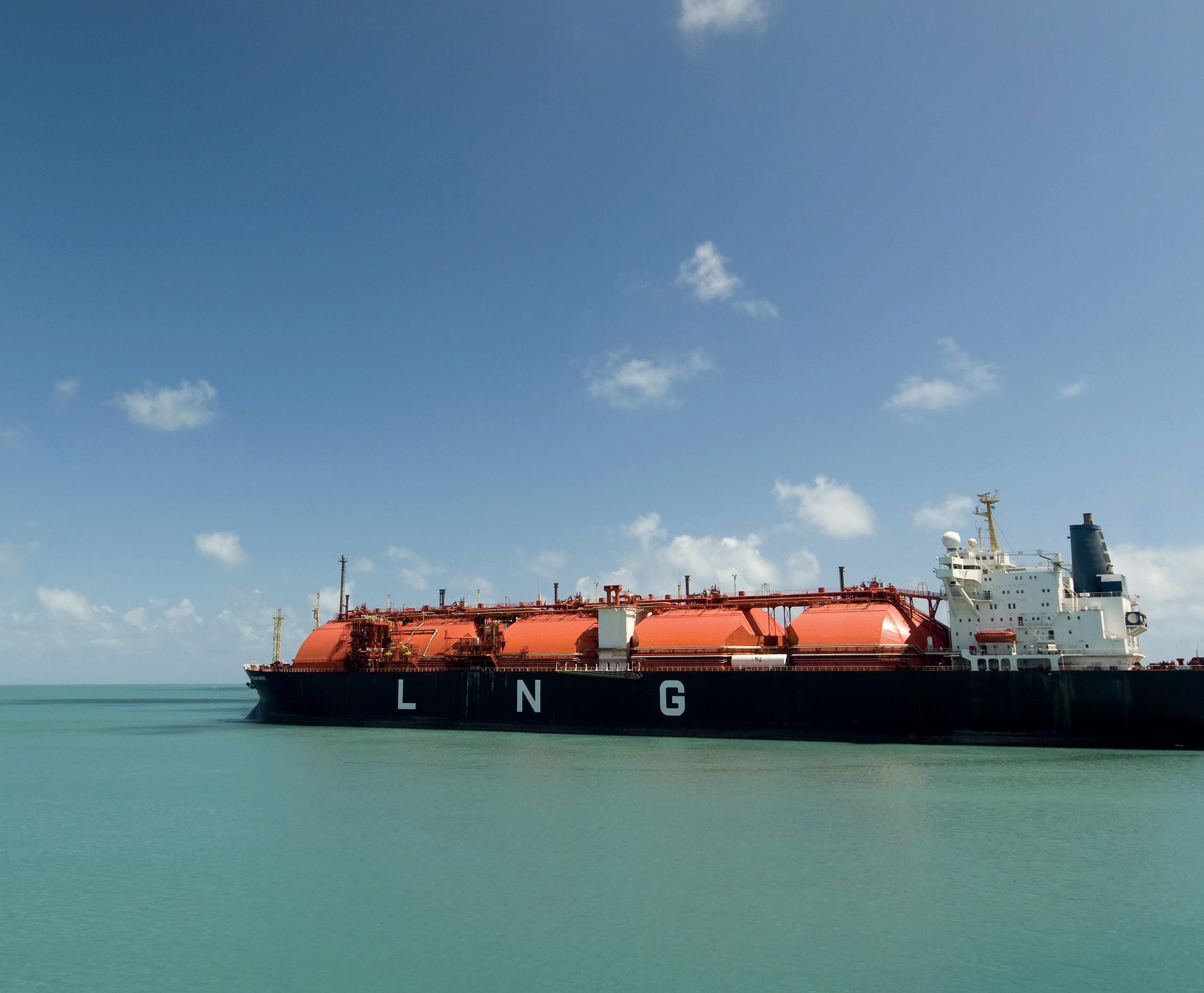
Subscribe online at: www.lngindustry.com/subscribe
Together, we create the most distinctive and integrated welding solutions for the construction of reliable and sustainable pipelines.
In everything we do, we maintain the highest standards. Or as we call it: The Qapqa promise.
• Increase productivity
• Increase quality
• Lower repair rates
• High level of support
www.qapqa.com

