


REGIONAL REPORT: NORTH AMERICA
16 C.C.U.S.A.
Dr. Elizabeth Moore, a research scientist at MIT’s Concrete Sustainability Hub, sat down for an interview with Rick Bohan, the Portland Cement Association’s Sr. Vice President of Cement, to discuss her work and the ongoing drive for decarbonisation in the US cement industry.
COVER STORY
22 Industry 4.0 – Are We There Yet?
Anders Noe Dam, FLSmidth Cement, explores why the cement sector lags in embracing Industry 4.0 technologies and highlights key opportunities to accelerate the digital transformation of cement plants.
AIR CANNONS & SILO CLEAN-OUT
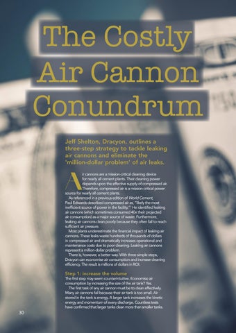
30 The Costly Air Cannon Conundrum
Jeff Shelton, Dracyon, outlines a three-step strategy to tackle leaking air cannons and eliminate the ‘million-dollar problem’ of air leaks.
36 Can You Handle Alternatives?
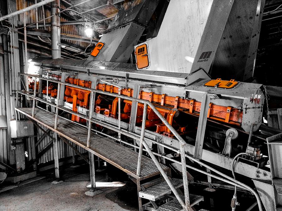
Alan Highton, Martin Engineering, examines challenges and raises solutions for handling alternative feedstocks in cement plants.
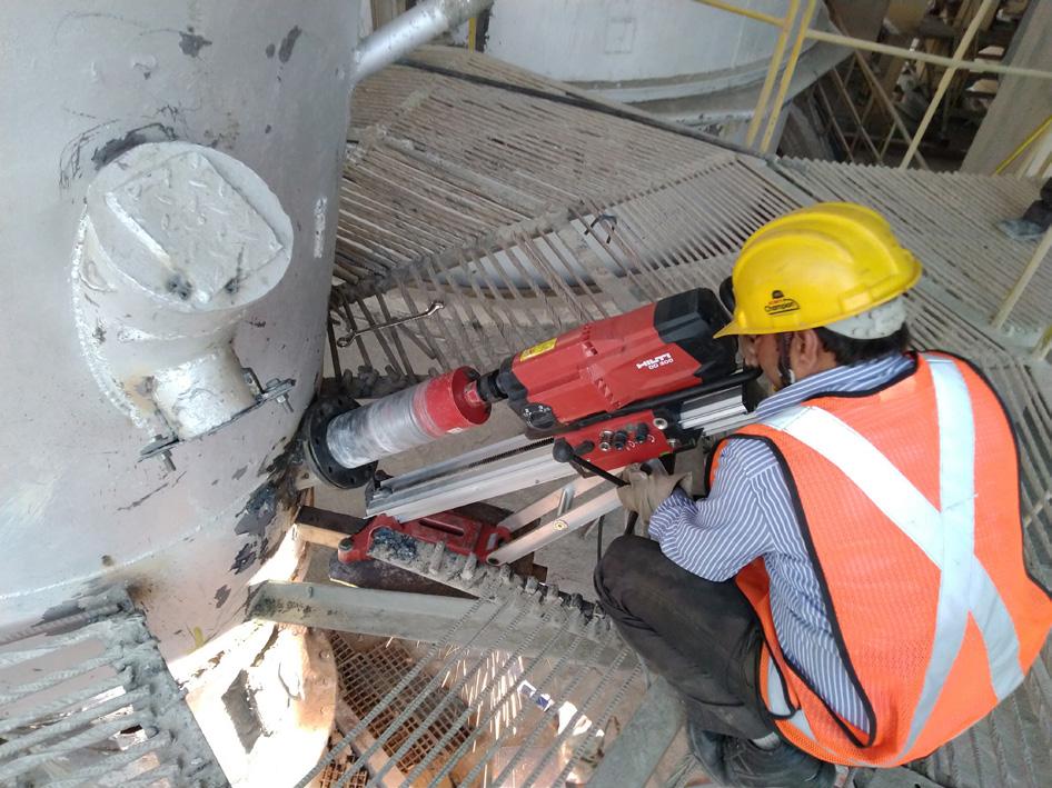
44 Successful Silo Solutions
Kearsten Huffman, Mole•Master Services Corporation, highlights the importance of proactive cement silo cleanout and inspection to prevent costly downtime, improve storage capacity, and ensure operational safety.
RAW MATERIAL PROCESSING
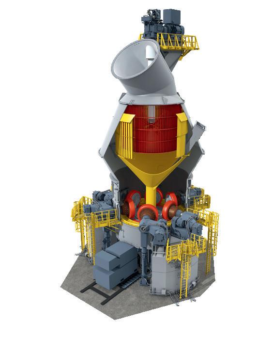
49 Crushing The Limits
Manuel Mühlbacher, Christian Pfeiffer, highlights innovations in roller press technology, focusing on enhanced reliability, simplified maintenance, and greater efficiency for raw material processing.
FLSmidth Cement is a technology and service supplier with a passion to help our customers produce cement efficiently. With over 140+ years of pioneering new innovations including over 50 years of developing and delivering advanced process control systems, we have been at the forefront of helping our industry benefit from digital technologies. Industry 4.0 promises a step change in efficiency, reduced waste, improved quality and cost savings. However, we are seeing many producers struggle to implement these technologies at scale. Our Cover Story, ‘Industry 4.0 – are we there yet?’ (pg 22), explores why the cement industry seems to be struggling to implement the latest digital technologies at speed and what can be done about it.


ADDITIVES & GRINDING AIDS
52 Stronger Blends, Greener Ends
Mike Stanzel & Oliver Sohn, Chryso North America, present a multilayered approach to maximising blended cement performance for use in concrete.
61 Great Gains With Grinding Aids
Gopala Rao Dhoopadahalli and Sheo Pujan Pandey, UNISOL CHEMTECH LIMITED, examine the role of grinding aids in enhancing the productivity, efficiency, and sustainability of cement production.
PYROPROCESS OPTIMISATION
71 Pushing Preheater Potential
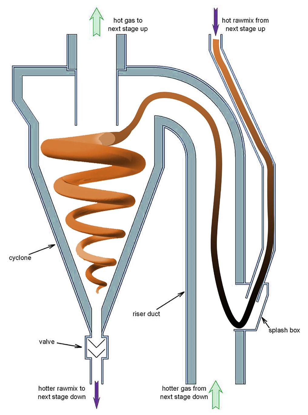
Lars Andersen, HASLE Refractories, explores the critical role of dip tubes in preheater cyclones and highlights how the latest generation of vortex finders is delivering extended lifetimes and improved process stability.
79 Marvels of MI-CFD Mechanics
M. Akritopoulos and T. Abbas, Cinar, explore the advantages of mineral interactive computational fluid dynamics (MI-CFD) in enhancing combustion efficiency, optimising alternative fuel use, and addressing challenges in the cement industry.
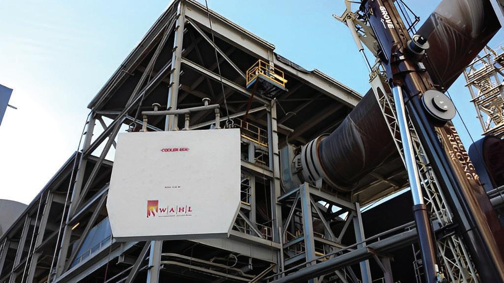
86 A Once In A Decade Chance
Katie Grube, a writer for the refractory, cement, packing, and lime industry, explains how a custom-engineered suspended platform revolutionised furnace refractory reinstallation, improving safety and efficiency during a shutdown project.
AIR POLLUTION CONTROL
92 24 Hour Baghouse Boost
Steve Klein, IAC, outlines how targeted interventions can optimise baghouse performance in just 24 labour hours.
101 Optimising HCL and SO2 Abatement
Ian Saratovsky, Gerald Hunt, and Travis Reynolds, Lhoist North America, explore key strategies for optimising HCl and SO2 abatement in cement production.
GEARS, DRIVES & MOTORS
111 Gear Up For Success
Mohamed Rezk, MAAG Gear Middle East and Sub-Sahara Africa, highlights a gearbox replacement project in Iraq that increased production and reduced energy consumption.
Powering Production With Predictive Maintenance
Andy Turner, SEW-EURODRIVE UK, discusses the benefits of using predictive maintenance software to reduce downtime in the cement industry.
DECARBONISATION
120 Turning Tyres Into Tomorrow Molins demonstrates how an end-of-life tyre recycling project is advancing decarbonisation efforts in the cement industry.
DIGITALISATION
124 Digitalising Cement Manufacturing Ighnatios Maatouk, ES Processing, explains how AI and machine learning are driving the digital transformation of cement manufacturing processes.
129 The Future Is Digital Ashutosh Dave, Schneider Electric, explores how digitalisation is key to tackling the challenges facing the cement industry, from improving competitiveness to addressing sustainability goals.
PLANT DESIGN
132 Tailored Foundations thyssenkrupp Polysius reveal why prioritising proven equipment and adaptive workflows is key to rapid plant ramp-up and sustained profitability.


An industry-leading performance spectrum coupled with exceptionally low energy consumption and other technological advantages ensure that Pfeiffer mills and machines keep your CO2 footprint smaller than that of others. Ask us about it!
Sustainability going forward – Getting it done!


ALFIE LLOYD-PERKS, EDITORIAL ASSISTANT

Erod.hardy@palladianpublications.com
Sales Manager: Ian Lewis ian.lewis@palladianpublications.com
Sales Executive: Sophie Birss sophie.birss@palladianpublications.com
Head of Events: Louise Cameron louise.cameron@palladianpublications.com
Event Coordinator: Chloe Lelliott chloe.lelliott@palladianpublications.com
Digital Events Coordinator: Merili Jurivete merili.jurivete@palladianpublications.com
Digital Content Coordinator: Kristian Ilasko kristian.ilasko@palladianpublications.com
Junior Video Assistant: Amélie Meury-Cashman amelie.meury-cashman@palladianpublications.com
Digital Administrator: Nicole Harman-Smith nicole.harman-smith@palladianpublications.com
Administration Manager: Laura White laura.white@palladianpublications.com
Reprints reprints@worldcement.com

xactly one year ago, this column showcased the US cement industry’s unprecedented leap toward decarbonisation, propelled by US$1.2 billion in federal funding under the Bipartisan Infrastructure Law and Inflation Reduction Act. For an industry long seen as a climate laggard, it was a moment of reinvention – proof that cutting emissions could align with economic ambition. Today, that progress is undeniably caught in the crossfire of shifting trade dynamics. The Trump Administration’s proposed 25% tariffs on cement imports from Canada and Mexico – suppliers of nearly a third of US cement demand – have thrust the sector into a paradox: can domestic manufacturing ambitions coexist with the global supply chains underpinning America’s infrastructure and clean energy boom?
Mike Ireland, PCA President and CEO, framed the dilemma starkly: “the industry believes 25% tariffs on cement imported from Canada and Mexico could adversely affect energy and national security while delaying infrastructure projects and raising their costs.”His warning cuts to the heart of the industry’s dual mandate – accelerating decarbonisation while navigating protectionist headwinds. Yet even as these tensions persist, the cement industry is responding with solutions that bridge competing priorities. Beyond tariffs and trade debates, the sector is forging partnerships that sidestep polarisation, as seen in three ground breaking projects.
CBP019982
Annual subscription (published monthly): £160 UK including postage/£175 (€245) overseas (postage airmail)/US$280 USA/Canada (postage airmail). Two year subscription (published monthly): £256 UK including postage/£280 (€392) overseas (postage airmail)/US$448 USA/Canada (postage airmail). Claims for non receipt of issues must be made within 4 months of publication of the issue or they will not be honoured without charge.
Applicable only to USA and Canada: WORLD CEMENT (ISSN No: 0263-6050, USPS No: 020-996) is published monthly by Palladian Publications, GBR and is distributed in the USA by Asendia USA, 17B S Middlesex Ave, Monroe NJ 08831.
Periodicals postage paid at Philadelphia, PA and additional mailing offices. POSTMASTER: send address changes to World Cement, 701C Ashland Ave, Folcroft PA 19032
Copyright © Palladian Publications Ltd 2025. All rights reserved. No part of this publication may be reproduced, stored in a retrieval system, or transmitted in any form or by any means, electronic, mechanical, photocopying, recording or otherwise, without the prior permission of the copyright owner. All views expressed in this journal are those of the respective contributors and are not necessarily the opinions of the publisher, neither do the publishers endorse any of the claims made in the articles or the advertisements. Uncaptioned images courtesy of Adobe Stock. Printed in the UK.
Palladian Publications Ltd
15 South Street, Farnham, Surrey GU9 7QU, UK
Tel +44 (0)1252 718999
Email: mail@worldcement.com Website: www.worldcement.com
Consider National Cement’s ‘Lebec Net Zero’ project in California. Funded by a US$500 million DOE grant and developed with Carbon TerraVault, this initiative blends carbon capture, biomass fuels, and limestone calcined clay cement (LC3) to eliminate 1 million tpy of CO2 by 2031. CEO Eric Holard sees it as a blueprint for reindustrialisation: “We are making a significant investment because we believe in creating a cleaner future and bringing innovation to domestic manufacturing.” The project’s reliance on locally sourced biomass and agricultural partnerships reduces the reliance on volatile supply chains by anchoring production within regional ecosystems.
Meanwhile, Terra CO2’s OPUS technology – a low-carbon cement substitute – offers a masterclass in pragmatic innovation. Backed by a US$52.6 million DOE grant and investors including JustClimate, its new Texas plant produces carbon-cutting cement without retrofitting existing infrastructure. In an era of trade volatility, such adaptable solutions buffer the industry against supply chain shocks.
Cemex’s Knoxville Test Center, supported by a US$101 million DOE initiative, exemplifies academia-industry collaboration. Partnering with the University of Illinois, the facility trials next-generation carbon capture technologies under real-world conditions. “Through collaboration and continuous innovation with the University of Illinois and industry peers, Cemex is committed to advancing decarbonisation solutions,” says Cemex US President Jaime Muguiro.
These projects share a common thread: they leverage collaboration to turn political and economic pressures into catalysts for innovation. This ethos reached its zenith at March’s EnviroTech 2025 conference in Athens, where 300+ industry leaders transformed ancient Greece into a modern agora of climate solutions. Against debates over tariffs and trade, the event served as a potent reminder – decarbonisation thrives not in isolation, but through alliances that transcend borders and boardrooms. Don’t forget to mark your calendars: EnviroTech returns in 2026 to explore the next frontier of industrial sustainability.

future,” said Ireneusz Kulka, Country Lead of EDP in Poland.
Cemex has signed an agreement with EDP Energia Poland to build solar installations at several Cemex plants in Poland, with a total capacity of over 14 MWp. This investment is part of Cemex’s global ‘Future in Action’ strategy to combat climate change.
Currently, Cemex has one solar farm at its ready-mix concrete plant in Pruszków. New solar installations will be added to cement plants in Chelm, Rudniki, and Gdynia, as well as concrete plants in Myslowice, Warsaw Annopol, Lublin, Szczecin, and Gdansk. These installations will start operating in the second quarter of 2025 for the concrete plants. For the cement plants, the schedule assumes PV generation will begin in the first quarter of 2026
The project will be carried out in collaboration with EDP Energia Polska, under a 15-year agreement where EDP will install and manage the solar installations, providing clean energy to Cemex facilities.
“Cemex sets ambitious decarbonisation goals, and investing in renewable energy is an important step towards reducing emissions. The concluded agreement is important in this context because it will guarantee us access to green energy in the long term. Additionally, the mentioned contract will enable the diversification of energy sources powering our plants,” said Michal Weglorz, Regional Energy Negotiator at Cemex Poland.
“We are glad that Cemex Poland, as a leader in its industry, has chosen photovoltaic solutions from EDP to implement its ambitious decarbonisation goals. This cooperation is part of our mission to support the energy transition and provide clean energy for every type of industry. We are convinced that Cemex’s investments in renewable energy will contribute to building a sustainable future and will become an inspiration for other companies from the energy-intensive sector. At EDP, we make every effort to be a reliable partner for our clients and, together with them, implement projects that have a real impact on reducing emissions and protecting the climate. In Poland, we have installed nearly 270 MWp of power in various facilities, thus supporting businesses in building a sustainable
Carbon TerraVault and National Cement sign MOU for California’s first net zero cement facility
California Resources Corporation and its carbon management business, Carbon TerraVault (CTV), announced the signing of a Memorandum of Understanding (MOU) with National Cement Company of California Inc. (National Cement) to provide carbon management services for the ‘Lebec Net Zero’ – a first-of-its-kind initiative to produce carbon-neutral cement at National Cement’s facility in California.
CTV plans to develop transportation and sequestration solutions for up to 1 million metric tpy of CO2 emissions captured from National Cement’s plant in Lebec, Kern County, California.
Captured CO2 is expected to be safely transported and securely stored in CTV’s underground storage reservoirs, contributing to California’s industrial decarbonisation efforts.
The project is expected to be California’s first net-zero cement facility, integrating carbon capture technology, utilising locally sourced biomass fuel from agricultural byproducts, and producing limestone calcined clay cement (LC3).
This effort aligns with Kern County’s Carbon Management vision, promoting economic growth, job creation, and tax benefits for local communities.
The project was one of 33 selected by the US Department of Energy (DOE) for funding under the Industrial Demonstrations Programme as a public-private partnership, with the DOE committing up to US$500 million in matching funds to accelerate its development.
Pending customary approvals, operations are expected to start in 2031.
Francisco Leon, President and Chief Executive Officer of CRC, emphasised the significance of this partnership: “This MOU with National Cement underscores the increasing demand for innovative decarbonisation solutions within California’s industrial sector. Achieving carbon neutrality in the cement industry requires bold action, and this partnership is a critical step in developing the state’s first carbon capture, transport, and storage project for this essential sector. We have a proven
bauma 2025
07 - 13 April, 2025
Munich, Germany bauma.de/en/trade-fair
IEEE-IAS/PCA Cement Conference
04 – 08 May, 2025 Birmingham, AL., USA www.cementconference.org
CEMENTTECH 2025
15 – 17 May, 2025
Hefei, China www.cementtech.org
FICEM TECHNICAL CONGRESS
08 – 11 September, 2025
Peru www.ficem.org
POWTECH
23 – 25 September, 2025 Nürnberg, Germany www.powtechtechnopharm.com
AUCBM AICCE28
11 – 13 November, 2025 Dubai, UAE www.aucbm.net
carbon management expertise and strategically located CO2 storage assets, allowing us to deliver innovative, reliable, and economically viable energy transition solutions.”
Eric Holard, Chief Executive Officer of National Cement, commented: “This is an exciting and transformative project for the cement industry. We are making a significant investment because we believe in creating a cleaner future and bringing innovation to domestic manufacturing. CTV’s leadership in safe and responsible carbon management, combined with our strategic and operational alignment, provides a clear pathway for this project being successful.”
Including this MOU with National Cement, CTV’s total carbon capture and sequestration (CCS) projects under consideration now stand at nearly 9 million tpy of CO2 emissions, reinforcing its domestic leadership in industrial decarbonisation and carbon storage solutions.
Hoffmann Green strengthens its partnership with Trecobat
Hoffmann Green Cement Technologies have announced the extension of its partnership with Groupe Trecobat, France’s 3rd largest builder of single-family homes. From March 2025, Hoffmann Green 0% clinker cements will be widely deployed on more than 100 Trecobat homes in the west of France. Founded in 1972, the Trecobat Group is a leading player in the construction of single-family homes, with sales of €203 million in 2023 and a strong territorial presence covering all the Grand Ouest region. Since January 2024, the partnership with Hoffmann Green has enabled Trecobat to accelerate its transition to sustainable construction by using 0% clinker cements for its Trecobat Green and Trecobois homes, which combine comfort and environmental performance.
After a successful first phase of trials and tests in 2024, Trecobat was convinced by the quality of Hoffmann Green’s decarbonised cements.
From March 2025, Trecobat confirms its commitment by deploying these solutions on more than 100 Trecobat Green and Trecobois homes in the West of France. This milestone represents a key step in the industrialisation of low-carbon cements for residential construction.
This deployment is based on a technical synergy between Hoffmann Green’s H-UKR cement and prefabricated floor systems from Fimurex Planchers, a specialist in the conception of reinforced concrete elements for single-family homes. This innovation enables decarbonated floors to be integrated into Trecobat Green and Trecobois wood-frame houses.
Thanks to the combination of the three partners’ cutting-edge technologies, the requirements of the 2031 threshold of the RE2020 environmental regulation are already anticipated, demonstrating their determination to accelerate the ecological transition and reduce the carbon impact of the building sector. The ATEx obtained in November 2024 for this application validates the relevance of this approach and paves the way for its wider implementation.
• BELT CLEANERS
• IDLERS
• IMPACT BEDS & LOAD ZONES
SUPPORT SYSTEMS
• POINT CLOUD SCANNING
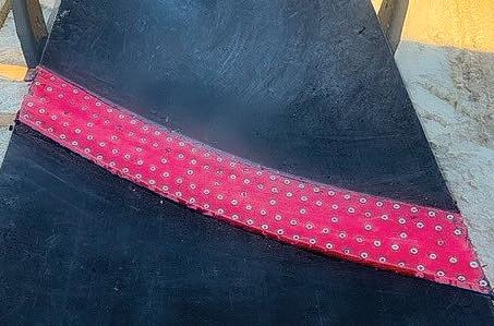
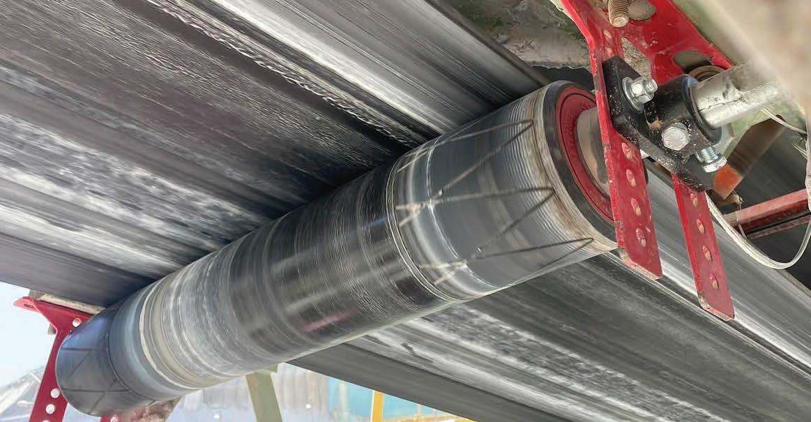
• PULLEY LAGGING
• SAFETY EQUIPMENT & GUARDING
• SKIRTBOARD & SKIRTING SYSTEMS
• CONVEYOR TRANSFER CHUTES (DESIGN & FABRICATION)
• VULCANIZING EQUIPMENT & MECHANICAL FASTERNERS
• WEAR LINERS
• CUSTOM URETHANE PRODUCTS
Hoffmann Green relies on a vast network of partners with ready-mix concrete plants to deliver its products to Trecobat construction sites in Western France. This optimised territorial network guarantees an efficient supply of Hoffmann Green’s decarbonised concrete to all single-family home building sites.
The intensification of this partnership with volume commitments enables Hoffmann Green to pursue its diversification strategy and accelerate its sales momentum on the French market. This strategic step testifies to the growing acceptance of decarbonised solutions by key players in the construction industry, consolidating Hoffmann Green’s position as an innovation leader in the sustainable construction sector.
Julien Blanchard and David Hoffmann, Co-founders of Hoffmann Green Cement Technologies, say: “We are delighted to be taking this new step with Groupe Trecobat to build more than 100 single-family homes from March 2025 in Western France. This new development will enable us to consolidate our presence in the single-family home market and reinforce our impact in eco-responsible construction.”
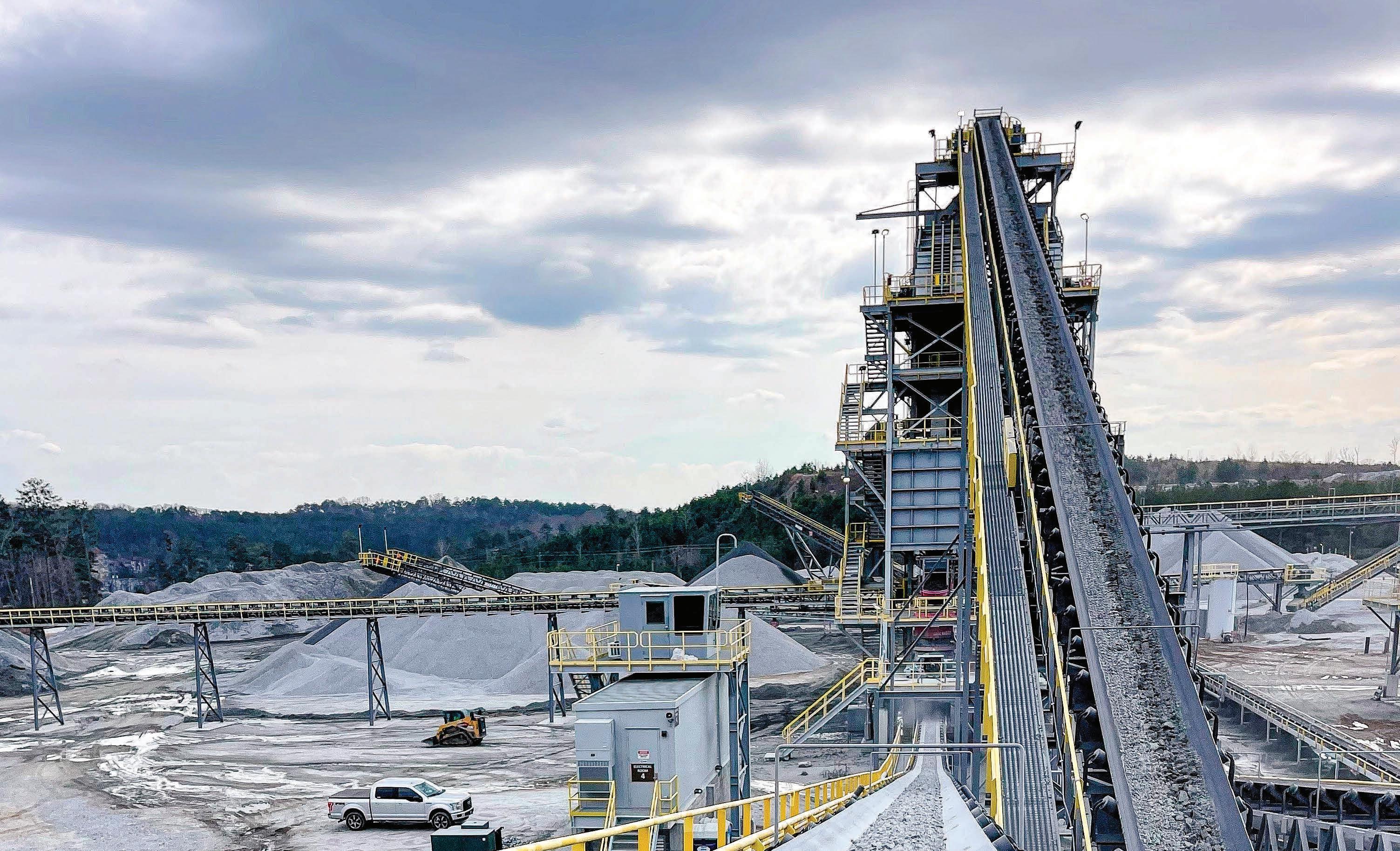
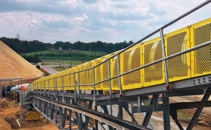
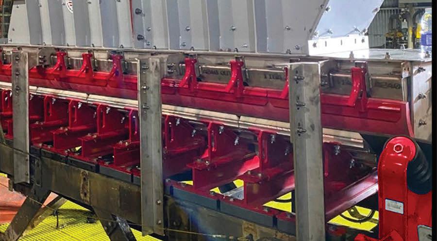
Breedon Group’s Hope Cement Works is located near to the village of Hope in Derbyshire, England. It is recognised as the UK’s largest cement plant and is integral to Breedon’s cement manufacturing capabilities. In order to sustain the processing of quarried limestone required for cement manufacturing, Breedon recently executed a major project to replace its 1940’s Fuller Traylor primary gyratory crusher with a new 1250 tph primary gyratory crusher, supplied by FLSmidth. Quarry Manufacturing and Supplies Ltd (QMS) were the lead partner in the installation, with the overall project being managed by the Projects Team at Hope, alongside a team of trusted contract partners.
Hope’s cement manufacturing process starts in its quarries, which at Hope comprises of two sources of limestone: high silica limestone and low silica limestone. The quarry’s upper beds have more of the high silica limestone due to their high chert content. Further down in the quarry is where the
lower silica limestone is located. There are currently 13 operational benches in total in the limestone quarry. In addition to the limestone material, shale is also used from an adjacent quarry on site, both the limestone and shale quarrying operations are integral to the cement manufacturing plant.
More than half the cement that is made at Hope Works is transported in bulk via rail to depots in the Southeast (Dagenham and Theale), West Midlands (Walsall) and North of England (Dewsbury), ensuring the final product is delivered as sustainably as possible. Additionally, Breedon has import terminals to supply its customers in Northern England (Blyth and Runcorn), and in Scotland (Leith).
In order to sustain operations, Breedon installed a new gyratory primary crusher in September 2024. The site had operated and maintained the previous Fuller Traylor crusher since its installation in 1952, with the body of the machine being completely original since its installation. Due to advancements in primary crusher technology, and a desire by the business to improve the maintainability of the crusher, plans for the replacement of the original crusher were put in place in 2022.
The project involved the installation of a single, new primary crusher and associated equipment which was installed on the limestone crushing line. The limestone crushing line further consists of a twin line secondary and tertiary crushing stage, comprising of state-of-the-art QMS B6 cone crushers. The task of pre-assembling the new FLSmidth crusher, demolishing and removing the old Traylor crusher, and finally installing the new FLSmidth crusher, was given to QMS who worked in close partnership with the Breedon team at Hope, their contract partners and equipment suppliers FLSmidth.
George Close, UK sales director at QMS, explains: “Working closely with FLSmidth, we had to first build up the new gyratory crusher. This was a time consuming and exacting process, as we were working to tight deadlines and the crusher had to be assembled on site. This site assembly was the first time all the crusher parts had been together, as the components were delivered by FLSmidth from all over the world. This took approximately five weeks. The second stage was to remove the old primary Traylor gyratory crusher; this utilised QMS’ expertise and experience gained on working
with gyratory crushers throughout the world. This took two weeks, working 24/7, and was finally completed in mid-August (2024).
“The third and final stage of the project was the actual installation of the new crusher, this again further necessitated working round the clock, night and day, taking over five weeks to complete. In addition, the new crusher has a QMS manufactured, bespoke stainless steel lubrication system which is now integral to the crusher’s operation. We further assisted through commissioning of the crusher, alongside the Breedon and FLSmidth teams, thereby ensuring that it was fully operational.”
Alcemy reaches new milestone and continues its global expansion
Alcemy GmbH reaches new milestone with global expansion and organisational changes.
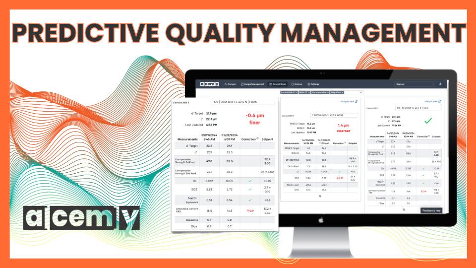
Alcemy GmbH proudly announces its latest achievements in the pursuit of helping customers optimise cement and concrete quality through cutting-edge artificial intelligence software. Since its inception in 2018, Alcemy has been revolutionising the construction industry and has now reached an extraordinary milestone: its advanced AI-based software is utilised in 30 cement plants worldwide, optimising the production of over 30 million tpy of cement. This significant achievement not only underscores the effectiveness of the technology but also highlights the trust and confidence that customers – the true decarbonisation heroes – place in Alcemy’s solutions.
Alcemy’s global footprint has expanded remarkably, now present in 12 countries and working with 15 unique customers, including global cement production leaders. To further bolster its capabilities and prepare for the next phase of growth, Alcemy has
implemented strategic organisational adjustments that align with its vision for the future. Alcemy is pleased to announce that Oliver Kanders, who has been with Alcemy since 2023 and previously served as Head of Revenue, will now assume the role of General Manager for the Cement Product Line. Oliver’s extensive experience and deep understanding of the industry will be instrumental in steering the product line to new heights of success. Additionally, Alejandro Espejel, who has been with Alcemy since 2024 and formerly held the position of Business Development for the Americas, will now take on the role of Head of Global Sales. These organisational changes are designed to streamline operations and enhance Alcemy’s focus on delivering exceptional value to its customers.
Alcemy’s ‘Software as a Service’ is rapidly becoming the go-to solution for cement producers seeking tighter quality control through predictive and prescriptive analytics. These capabilities enable cement producers to improve the performance of their products, optimise costs, and reduce their environmental footprint.
Alcemy will be actively participating in all major industry conferences throughout 2025. Notably, Alcemy will be present at the IEE/PCA Conference in Birmingham this May, followed by FICEM’s Sustainability Congress in Ecuador later the same month. This presence underscores Alcemy’s commitment to staying at the forefront of industry developments and sustainability initiatives.
Aggregate Industries has rebranded to Holcim UK as part of a strategic shift to provide the construction industry with seamless access to the latest sustainable building solutions.
With over 200 sites and 4000 employees across the UK, Aggregate Industries’ 25 brands are uniting under Holcim UK to drive this growth. Building on trusted partnerships, the move is also set to provide customers with access to more seamless, enhanced services and sustainable solutions.
Holcim UK’s strategic focus centres around leading the mission to make sustainable construction a reality, focusing on decarbonisation, nature, circularity, and innovation. Its aim is


PSCL’s Raw Mix Control System combines them better than anything else out there.
Minimise variability in raw mix proportions. Reduce thermal stress on your preheater and kiln. Lower fuel consumption.
Achieve higher kiln alternative fuel substitution rates and stricter control over your emissions without jeopardising the quality of your clinker.
And as an ongoing subscription, it’s kind to your cashflow.
to achieve this through both its commitment to reducing its own impact on communities and the planet, in addition to driving positive change for the industry and customers through its expert teams and sustainable solutions.
The consolidation comes as the construction sector faces increasing pressure to deliver more homes and buildings in line with emissions reduction and environmental policy, amid predicted growth of up to 10% by 2026.
Alongside a target to accelerate green growth, Holcim UK is committed to expanding the uptake of sustainable building materials in the UK. Currently a third of its turnover comes from sustainable products and it is aiming to continue to increase this in the next five years.
Key to this will be circular product innovation through construction demolition materials (CDM), targeting an increase of CDM used in products from 2 million t to more than 5 million t by 2030.
Following 20 years as a UK-based subsidiary of Holcim Group, the new direction sees Aggregate Industries align more closely with its Swiss-based parent company, which operates across 70 countries and employs over 60 000 people worldwide. Holcim UK will leverage global insights, innovation, and expertise in sustainable solutions from Holcim Group to enhance Aggregate Industries’ existing rich UK heritage and its understanding of the local market.
This presence in the UK market has already seen the launch of product ranges such as ECOPact low carbon readymix concrete, ECOPlanet range of low carbon cement, and its ECOCycle range of products, which are made from at least 10% recycled materials.
This focus on circularity is underpinned by continued investment, including recent acquisitions of CDM specialist companies Land Recovery and Sivyer, in addition to innovations such as neustark – the technology which permanently locks carbon removed from the atmosphere into processed demolished concrete for new products.
To support customers further, Aggregate Industries will also continue its focus on knowledge sharing and best practice through its trusted partnerships. This includes initiatives such as the Holcim Sustainable Construction Academy, which offers free CPD-certified courses on low-carbon, circular and regenerative design concepts, developed with top global institutions and architecture firms.
Speaking on the direction, Lee Sleight, CEO of Holcim UK, said: “Our evolution from Aggregate Industries to Holcim UK is much more than a rebrand. It represents a commitment to leading the sector towards a more sustainable future through a commitment to innovation and collaboration.”
“By uniting under one coherent brand, we can focus on driving sustainable growth for our business and many customers and suppliers we have formed strong partnerships with over the years. With such growth, we can continue to invest in the people and solutions capable of making a positive difference to customers and communities. Key to this will be our ongoing prioritisation of people, purpose and performance to achieve our ambitious revenue and sustainability growth targets.
“Through taking on the global brand, we can leverage Holcim Group’s global presence and the innovative solutions it has brought to a variety of different markets. With our renewed strategic direction, we will not only be able to reduce our environmental impact and make positive change as a business, but be a trusted partner to our customers as they aim to do the same.”
To mark the establishment of its new brand, Holcim UK has launched two initiatives to drive awareness for sustainability in construction and its strategic direction for making it a reality.
The first is the creation of its ‘Sustaina-billboard’, an environmentally-friendly billboard containing pollinating flowers, plants and seeds to support local wildlife, and a surrounding frame made from low carbon concrete and recycled aggregate materials.
Demonstrating its commitment to nature and biodiversity, the creation is designed to feed wildlife and insects around its Greenwich site, as well as highlighting the brand’s nature strategy, which will see it creating dedicated spaces for nature across more than 200 sites by the end of the year.
Holcim UK has also identified the specific areas where the construction sector needs to focus its efforts to overcome pressing sustainability challenges in its new report Making Sustainable Construction a Reality. Exploring the areas of decarbonisation, circular economy and waste reduction, smart construction, people and communities, and nature and biodiversity, Holcim UK is aiming to provide the wider industry with a series of steps that should be taken to progress towards making sustainable construction a reality.


Dr. Elizabeth Moore, a research scientist at MIT’s Concrete Sustainability Hub, sat down for an interview with Rick Bohan, the Portland Cement Association’s Sr. Vice President of Cement, to discuss her work and the ongoing drive for decarbonisation in the US cement industry.
Dr. Elizabeth Moore, a research scientist at MIT’s Concrete Sustainability Hub, thinks there should be more huddles among scientists, industry professionals, and US policymakers, as too often, these groups ‘stay in their bubbles’, which creates gaps in valuable communications that would help accelerate them toward their common goal: decarbonising the American cement and concrete industry.
Last Autumn, Dr. Moore closed in on one of the gaps, boarding the train from Boston, MA to the nation’s capital, to connect face to face with policymakers, which made for enlightening conversation.
Rick Bohan, the Portland Cement Association’s Sr. Vice President of Cement, spoke with Dr. Moore about her work, her Capitol Hill visits, and why it was so worthwhile to head to Washington.
Rick Bohan: What is the goal of this research you’re working on for the cement and concrete industry?
Dr Moore: "Our goal was to understand the real-world deployment costs for carbon capture technologies. When we began comparing some of the results in the literature, we realised that many studies were simply not capturing all of the costs associated with integrating a carbon capture system on site at a cement plant. Our goal was to really understand what was missing from those cost estimates – where are the gaps – and how we can provide more detail
in the overall analysis. We hoped that better information would give policymakers estimates they could use to design future incentives. After reviewing some of the policies around carbon capture and sequestration (CCS) such as the 45Q tax credit, we found that they weren't enough for many industries to actually adopt carbon capture. And so, through more detailed modelling, our hope was to find and add those missing pieces so we could have a full picture of overall costs.”
Rick Bohan: So – I know you went to Capitol Hill a short time ago. Can you tell me a little about that?
Dr. Moore: “Yes. I did go to the Hill last October, with the director of the MIT Concrete Hub, Dr. Randolph Kirchain, and with Portland Cement Association’s Senior Vice President of Government Affairs, Sean O’Neill.
We met with key decision-makers and policy stakeholders working to develop impactful strategies for their communities. When we sat down with them, we explained our key research areas at the MIT Concrete Sustainability Hub, and how we think our research can inform policies and future decision making for these leaders in regions with cement plants.
For example, we talked about different technologies and strategies that could help reduce their greenhouse gas emissions at cement plants in their area. A big part of the discussion was about what it would take to make these solutions work – like the need for new infrastructure, which could mean building in people’s backyards or using more land for infrastructure such as pipelines or storage sites. But we also highlighted the benefits: cleaner air, new jobs, and ensuring the long-term sustainability and resilience of local industries.
We hoped these conversations would highlight a range of cost-effective solutions for decarbonisation, while also bringing benefits to communities, helping them to understand the portfolio of solutions available to cement plants in their regions, and how we can demonstrate with research which policy and technology tools will be most successful to help them.”
Rick Bohan: How has what you’ve seen on the policy side informed what you’re looking at for future research?
Dr. Moore: “It was my first time going to D.C., going to the Hill, and I think that’s been a big missing piece for researchers. A lot of researchers, including myself, are in our bubbles. Our modelling and lab work are largely informed by existing literature and gaps in that literature and don’t always consider real-time industry developments.
So, going to D.C. was a very eye-opening experience to meet with the policymakers who are making these decisions and making a difference for communities in the US, both in the cement industry and beyond.
To be able to sit down and chat one-on-one, to understand some of their pain points and hear about the realistic barriers they’re running up against helps us in our research. For example, understanding the barriers helps us to reevaluate our modelling approach and refine the inputs we use, ensuring our models more accurately reflect real-world conditions.
I think it’s an invaluable experience to meet the people who are using academic research to make their decisions. More researchers should have the opportunity to engage in this way.”
Rick Bohan: How do you approach it from the standpoint of cement industry research, and how do you expand beyond cement applications? Imagine going to the Hill a second time, aiming to broaden your presentation to all industries because some lawmakers don’t have cement plants in their districts or are interested in concrete.
Dr. Moore: “That’s what makes some of the decarbonisation technologies so fascinating – they extend their impact beyond a single industry, impacting a broader range of stakeholders. Carbon capture, for example, or alternative fuels… these are potential strategies that will impact many industries and many communities.
I think looking at carbon capture and how it might impact the power grid is one example. I’ve done a lot of work in other industries, including the mining industry, where we’ve been looking at what the power portfolio of the future will look like, and wondering which technologies will be a part of this? What will be the mix of renewable energy technologies? Which energy storage technologies will support the grid?
For example, we may have renewable energy technologies, but there will be times when the sun isn’t shining and the wind isn't blowing, requiring reliable backup power sources. Beyond its role in decarbonising the cement industry and other hard-to-abate sectors, carbon capture is also being explored as a transitional technology – helping to shift away from fossil fuels and toward a cleaner, more resilient energy portfolio for the future.
I believe discussions with policymakers about carbon capture more in general, across industries is really helpful, and can help to identify some of the challenges that may arise
within their communities from these technologies coming on board.”
Rick Bohan: Considering the power portfolio, what do you as a researcher want the policy people to know, and what do you think the policy people want you as a researcher to know?
Dr. Moore: “From a research perspective, there are different optimisation models that look at costs, emission reductions, some of the regional constraints for deploying these different types of technologies, etc.
For example, in regions like New York, where hydropower is abundant, that resource may be a natural choice. However, in other areas, we assess factors like solar and wind patterns to determine the best energy solutions based on local constraints. By considering the unique resource availability of each location, we can recommend the most suitable technologies for sustainable and efficient decarbonisation. However, these recommendations don’t always account for other constraints, such as community pushback, land use concerns, or policy and regulatory challenges. And I think a policymaker would like me to understand that building these optimisation models is great to show an ideal picture, but in reality, the permitting, the land procurement – there are a lot of elements that go into decision making that researchers are not always thinking about, yet these factors also need to be considered in modelling for the future.
I think what I’d like policymakers to understand is that there are a lot of pieces to this puzzle. And the optimisation results can give us a starting point and a place to start a conversation about which technologies may be best for them to consider for their individual region. We can then work together to iterate on different potential scenarios based on how they see the future rolling out.
I think there’s an opportunity to work together more frequently where historically, that hasn’t always happened on a consistent basis. We should look at ways we can use both our knowledge and our tools for good.“
Rick Bohan: Given this disconnect between policy and research, how can academia address that so you’re working in parallel?
Dr. Moore: “At the CSHub, the research team has been working to connect with policymakers at all levels – from local to international – to share research that can inform better decision-making. We share our research through user-friendly tools, research briefs, and op-eds. Additionally, at MIT, the MIT Policy Lab helps researchers translate their findings into actionable policy insights, while the
new MIT Climate Policy Centre supports efforts to bridge the gap between climate science and real-world policy solutions.
I think more frequent communications with policymakers and researchers can create a dynamic exchange of ideas, allowing policymakers to quickly incorporate the latest research into decisions, while researchers gain valuable insights into practical, real-world challenges.”
Rick Bohan: Any closing thoughts about the work you’re doing now and how you’d like to see things progress in the future?
Dr. Moore: “When I first started with the Hub, I would listen to presentations about cement and concrete, and think, ‘this can’t be that interesting!’ I had an expectation that it was not going to be an interesting research area, and boy – have I been put in my place! This is one of the most fascinating research areas!
I think there is so much opportunity here to build stronger and safer infrastructure in a way that will reduce the environmental impact in the long run.
It’s funny. My family and friends now call me whenever there’s a natural hazard going on and say, ‘Well, how are we going to make sure we’re going to build more concrete structures?” That’s what happened with the California wildfires. My mom called and said, “Elizabeth, do you see that the only structure left standing was the concrete one? Did you tell them?” And I said, “They know, Mom!” And I think this is just an underrated area of research.
In the future, I hope more researchers go into this area with an open mind and see the benefits that concrete can really provide in a community. I’ve been lucky enough to have been with the research from the cement level all the way to the concrete level. I think it’s a fascinating space, and I think there’s a lot of opportunity for growth, and I’m really excited to see the cement industry hit its roadmap targets because – I think they will.”
Rick Bohan, the Senior Vice President of Cement at Portland Cement Association (PCA), has been at the forefront of research and technology throughout his career as a licensed professional engineer. As PCA’s lead on the development and now the implementation of its roadmap to carbon neutrality, Rick is passionate about engaging the industry as the solution to society’s grand challenge of global warming.
About Dr. Elizabeth Moore
Elizabeth Moore is a research scientist and programme manager at MIT’s Concrete Sustainability Hub (CSHub).
With the launch of the ECS/ControlCenter 9.1, we maintain our place at the cutting-edge of industrial process control and provide the foundation for further digital innovation.
Why upgrade?
ECS web app – Real-time data, anytime, anywhere
Seamless integration – Connect plant data via MQTT
AI-powered insights – Optimise with Python-based analytics
Future-ready – Scalable, secure, and hardware-agnostic

– are we there yet?
Anders Noe Dam, FLSmidth Cement, explores why the cement sector lags in embracing Industry 4.0 technologies and highlights key opportunities to accelerate the digital transformation of cement plants.
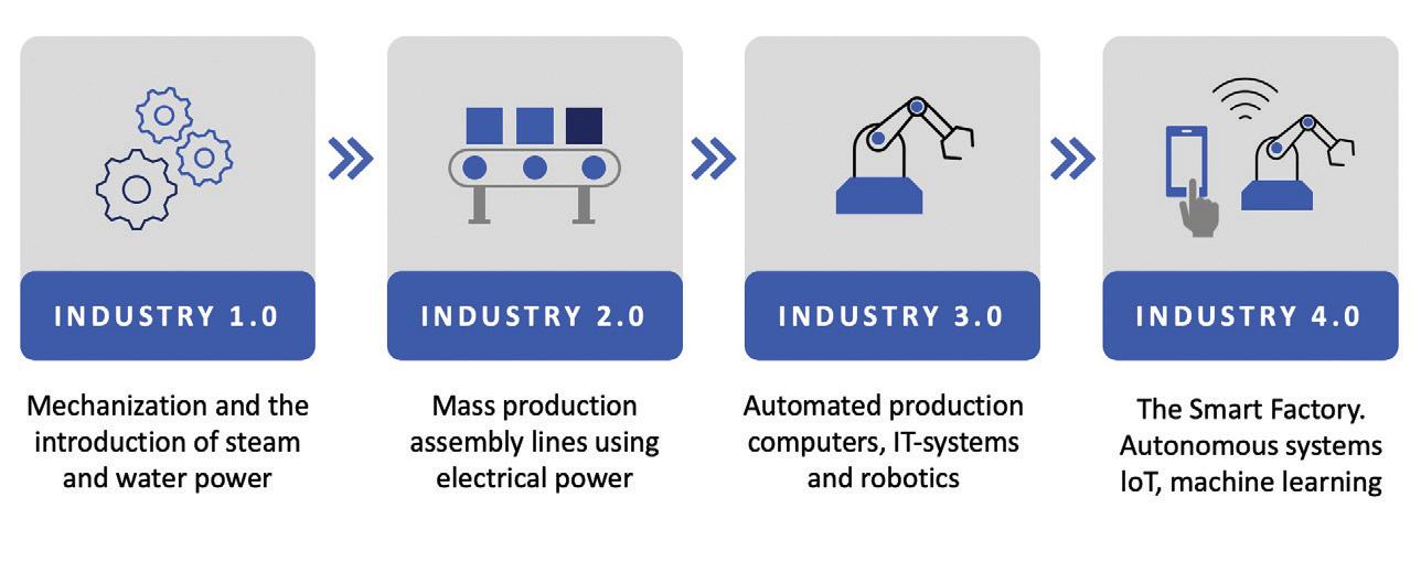
The world is currently experiencing the fourth industrial revolution – or Industry 4.0. This is an era of digital transformation characterised by the introduction of AI and machine learning, connectivity (the internet of things (IoT)), and big data – all of which are powered by cloud computing. To put it another way, there is much more computing power and much more storage. And, combined together, this is providing data analytics at an entirely new level. These are transformative times, with examples evident in nearly all aspects of life.
The pioneering cement producers who have integrated Industry 4.0 report remarkable benefits. Plants utilising smart sensors, IoT
devices, and real-time data analytics have experienced up to a 20% increase in overall production efficiency, 15% reduction in energy consumption, and a 10% decrease in raw material wastage.1 The tangible benefits of AI-driven tools are many:
f Lower environmental impact – greater efficiency reduces fuel and power use per tonne of cement while optimising clinker quality, enabling a reduced clinker factor.
f Enhanced quality – real-time process adjustments optimise blending, fuel/raw material feeds, and pyro stability for more consistent output.
f Carbon capture readiness – stabilised flue gas composition increases CO2 concentration which simplifies carbon capture implementation – and makes it much more cost effective.
f Increased uptime – continuous monitoring and stability reduce the frequency of issues and prevents minor issues from escalating into major failures.
It is hard to imagine any other investment having a more attractive ROI. One would assume that virtually all plants would be embracing Industry 4.0 immediately, and many are, particularly for applications regarding condition monitoring and proactive maintenance. But, from the perspective of advanced process control, the cement industry is not quite there. That is the inspiration for this article. This is not intended to be an in-depth technical piece, nor is this for the purpose to promote a specific offering. Rather, the objective is to explore why the cement industry seems to be struggling to implement the latest digital technologies at speed and what can be done about it.
The latest estimates suggest that just 30% of cement plants worldwide have begun implementing Industry 4.0 technologies in various stages of the process. That may sound
somewhat respectable, but that figure gives no indication of how far the plants have actually progressed with implementation, or even if the plant intends to rollout Industry 4.0 across the entire flow sheet rather than just isolated applications. So, what is going on here? Well, in short, it is not easy to move to 4.0 unless the plant has fully implemented 3.0 in a way that provides a solid foundation.
Let’s take a step back. Industry 3.0, also known as the digital revolution, initialised the automation and digitisation of manufacturing systems through solutions such as programmable logic controllers (PLCs).
Process control focused on the automation of linear tasks, reducing manual intervention and increasing the precision and speed of processes, resulting in a marked improvement in process efficiency and an easier path to a high-quality end product.
The scope of the solutions was either specific applications such as the pyro process or perhaps even multiple applications at a site. But, with few exceptions, the solutions always stayed within the gates of the plant. Understandably, the cement industry was focused on squeezing out as much value as possible, as soon as possible, and was largely successful. But, at the same time, much less effort was given to laying the groundwork necessary to support easy adoption of 4.0.
What are the barriers of implementing Industry 4.0 at scale?
Given the capabilities of the latest APC solutions, why is it that so many plants are lagging on the adoption of smart technologies?
f Lack of awareness – some in leadership may not appreciate how important it is or have the full perspective of their plant’s situations.
f Change management – embracing advanced process control software is a culture change for some operators. Without reinforcement such as periodic refresher training, there can be a risk of reverting to former practices.
f Trust – between cybersecurity concerns and the range of new solutions on the market, there is a lack of trust around which solution can deliver without risk.
f Immature technology – though there is a lot of potential out there, real impact will only be achieved when APC solutions are mature
enough and designed to be rapidly deployed from site to site, a capability many start-ups lack the experience to deliver.
f Cost – the lack of technical maturity also makes it harder to calculate an accurate ROI as few benchmarks or past examples are available to support estimates for the actual opportunity costs and future benefits.
f Data is not usable at scale – there is a lack of structured, high resolution data – often missing crucial metadata (such as calibration details and process changes) – which is essential for training robust algorithms.
First, plants as well as suppliers must deliberately put Industry 4.0 at the forefront of their automation strategies and make sure the proper foundation is in place. For example, at FLSmidth Cement, R&D roadmaps for each product are designed to capture the benefits of evolving AI solutions or other technologies. This includes the need to support the creation of usable data sets, mobility, and cloud computing so that AI solutions can be most effective.
Data quality and accessibility is the most prevalent and challenging obstacle that cement plants battle. Industry 4.0 solutions – especially AI-driven ones – require more than just sporadic historical records. A robust metadata foundation is essential, including calibration dates, process changes, and measurement precision. For some applications, having a time series of one year at a 10 second resolution is necessary. Without this level of detail, even well-collected data can be difficult for AI to interpret, limiting its ability to predict process behaviour and optimise operations.
To fully unlock AI’s potential, companies must strengthen their data foundations. Start by auditing current automation systems (OT architecture) to identify gaps in data collection and metadata. Ensure sensors are calibrated for and control systems ready for continuous, high-resolution data capture. Standardised, centralised data storage simplifies AI analysis. Next, structure metadata management by documenting process changes, calibrations, and measurement precision. Break down departmental silos and integrate data across systems. Partner with
experienced providers to build a scalable, future-proof architecture.
Sample data is an area of special concern as many plants still operate manual labs, but that data and the surrounding meta data is essential. The lack of such will severely strain efforts for clinker substitution. A sampling and lab audit will reveal a clear view of data quality, accessibility, and consistency, and help identify gaps that could undermine AI-driven optimisation. By tackling these areas early, plants can establish a strong foundation for a smooth and effective digital transformation. This will enable full scale implementation of data driven AI Process optimisation solution as they mature over the coming years.
free from vendor lock-in
In Industry 3.0, proprietary automation solutions were standard, and while not ideal, they were manageable. However, this lack of flexibility is causing frustration in today's digital landscape. Many plants now find themselves locked into vendor-specific systems that hinder integration, delay digital transformation, and drive-up costs. Companies struggle to adapt to new innovations and align with long-term operational goals without the freedom to evolve their technology stack.
It does not have to be this way.
Supplier-agnostic pathways are available to offer an alternative to vendor lock-in. One such pathway is the Open Process Automation Standard (O-PAS) from The Open Group. O-PAS provides comprehensive guidance for developing Industry 4.0 automation systems that are independent of proprietary technologies. It enables seamless integration across diverse systems, giving companies the freedom to create cost-effective, scalable, and interoperable digital transformation roadmaps. Open standards have accelerated innovation outside of cement; the industry must also fully embrace this practice. Is
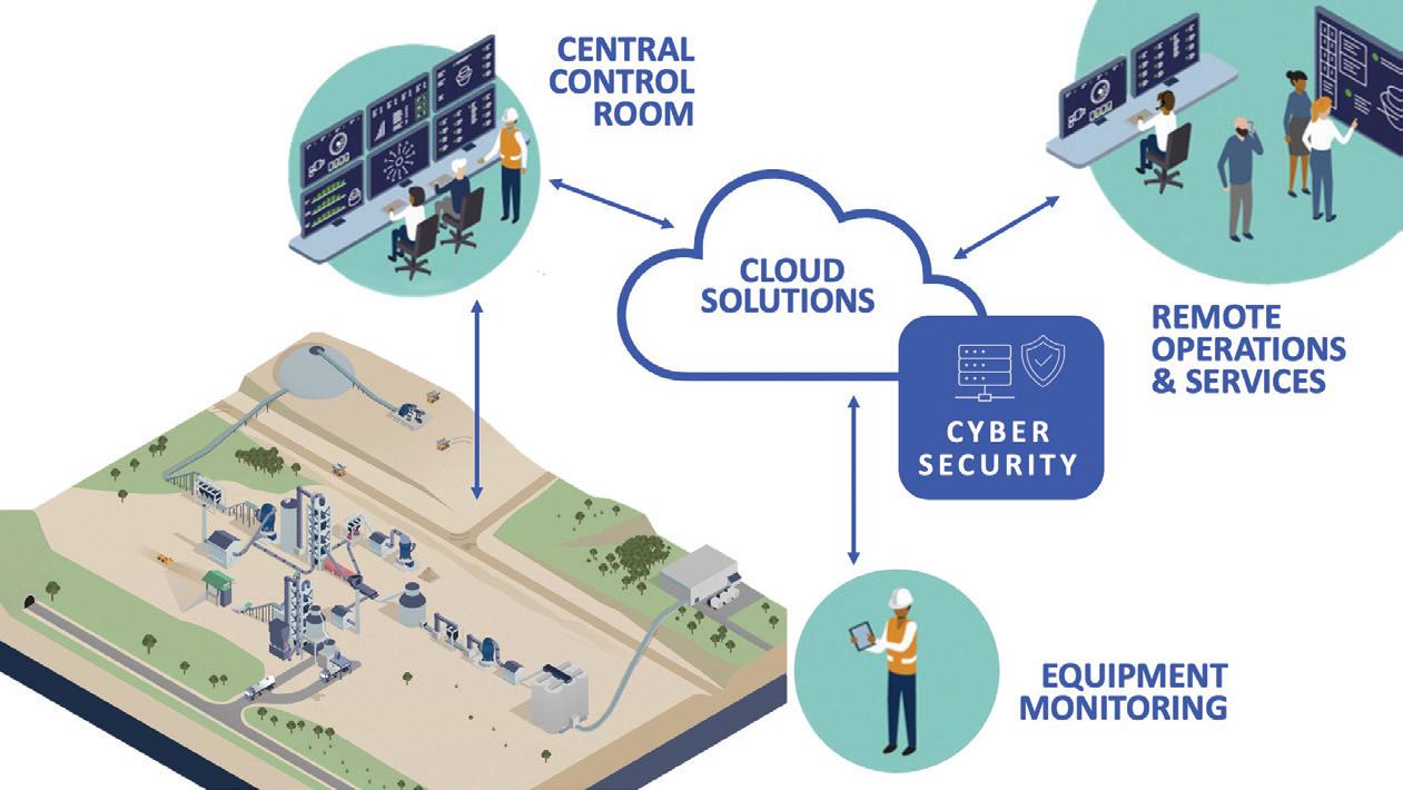
Many industrial automation systems are typically older, unpatched, and thus more vulnerable to cyberattacks, which was perhaps okay when they worked in isolation. However, advancing digitalisation and connectivity are exposing these systems to greater risks. Industry 4.0 is built on cloud computing. Typically, many AI providers structure and execute their solutions in the cloud. They run their algorithms and then send the outcome (set points and predictions) back to the plant. The IT and OT systems from Industry 3.0 were simply not designed for this as there was much less need for data exchange, which kept the risk of cyberattacks much lower.
Certainly, plants can open up the flow of data, but this is an extra step that tends to act as a speed bump. Although some have matured the ability to send data to the cloud, very few have the systems to take data back at the required speed and scale. Partnering with an experienced supplier who can design a secure architecture and implement best practices is key. FLSmidth Cement is confident of this need as it has been getting frequent requests for assistance from their customers. In fact, there were so many enquiries that FLSmidth Cement was inspired to launch a specific service package for cybersecurity assessments.
To fully harness the potential of next-generation optimisation solutions, all KPIs must be aligned so that the optimisation systems and algorithms are configured to give plants what they really want. However, in working with plants, FLSmidth Cement often uncovers competing priorities which can make everything more complicated and impede the best overall outcome.
What is the right trade between maximising alternative fuels in order to save money, versus getting better clinker quality such that more substitutions can be used to reduce CO2, versus getting a stable and ideal flue gas to enable carbon capture? It is unlikely that one can get them all perfectly achieved at the same time, but which should be prioritised over the others? And who decides?
For a given project, FLSmidth Cement usually have a primary contact at their customer. Sometimes that person will guide FLSmidth Cement to design a system that will achieve their own KPIs without full consideration for the greater good of the entire plant. It is not intentional or self-serving. Rather, FLSmidth Cement believes it is just organisational growing pains – because Industry 4.0 and plant-wide optimisation thinking is not yet fully part of the cultures. Consequently, at times, FLSmidth Cement has found itself playing the role of a detective to get the clarity and alignment
needed so that it can deliver the best overall solution.
In Industry 3.0, the normal go-to market strategy consisted of selling software with a perpetual licence. This model was widely accepted as a best practice by everyone involved. FLSmidth Cement’s customers owned the software outright, and in turn, received full payment upfront. FLSmidth Cement’s competitors did similar. However, updates were not automatic and plants often found themselves running with somewhat outdated versions.
To stay competitive, cement producers no longer have the luxury of waiting for a major upgrade to adopt new features – things are moving too fast. Consequently, FLSmidth Cement has transitioned to offering its optimisation software as a subscription-based service as opposed to a one-time purchase. In other words, rather than owning software, a plant receives optimising services that includes software and proactive monitoring of performance. This concept has been well-received by plants, however many have had the extra administrative hurdle of adapting their approach to budgets and purchasing KPIs. Furthermore, in the same spirit of delivering continuous performance, FLSmidth Cement has seen an uptick in enthusiasm for their PlantLine™ Service Agreements which include secure, trouble-free support with 24/7 coverage and customisable modules for cybersecurity, remote technologies, lifecycle management, and proactive maintenance.
Plants that fully adopt Industry 4.0 will have a powerful competitive advantage, accelerating efforts regarding productivity, decarbonisation, quality cost savings. Much of the technology is already available. And, with the right strategy in place, the obstacles can certainly be overcome. Begin by assessing the current digital maturity of the plant, with particular focus on the OT systems. Conduct audits on data, cybersecurity, and sampling and laboratory processes. Then, collaborate with industry experts to implement the next generation of advanced process control. The sooner action is taken, the sooner efficiency gains and sustainability improvements can be realised. The future of cement production is digital; delay may result in falling behind.
References
1. 'Pioneering the global cement industry', World Cement, 2024 – https://www.worldcement. com/indian-subcontinent/18032024/pioneeringthe-global-cement-industry/
Connect with Regal Rexnord at the 2025 IEEE PCA Cement Conference! Our broad portfolio of dependable products for the cement industry can provide the best solution for your conveyors, crushers, shaker screens, bucket elevators, industrial fan/cooling systems, and other critical applications. We create long-lasting solutions that are designed to withstand extreme temperatures and harsh environments for years of optimal performance.
Explore how Regal Rexnord’s power transmission solutions can help keep your systems running in the toughest cement applications.

Learn more at rrx.link/CementSolutions Visit us at BOOTH
• Plunger prevents blockages at sample gas entrance
• Large filter surface for dust-free gas sample
• Gas sample above water dew point temperature
• Suitable for hot/wet or cold/dry flue gas analysis
Probe gas entrance inside rotary kiln
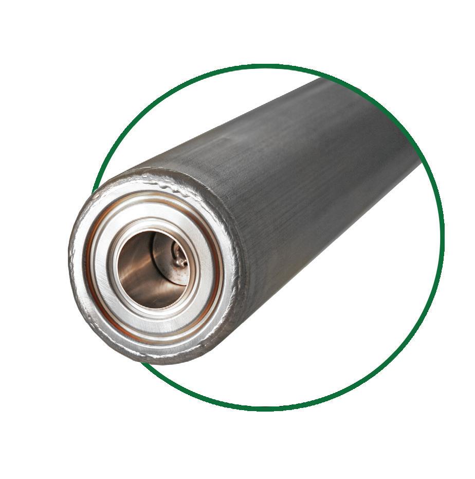
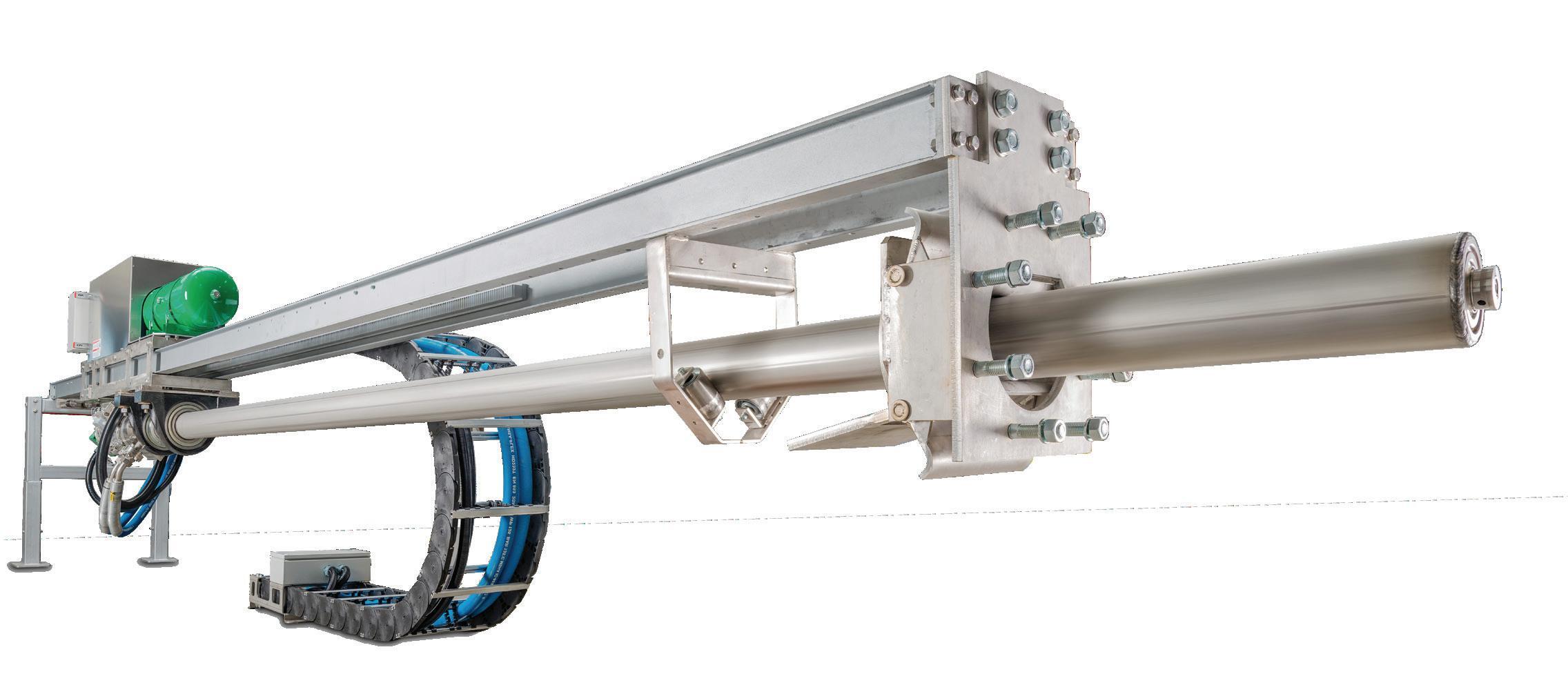


• Cyclic plunger movement with 7000 N
• Probe insertion/retraction force 20000 N
• Cyclic anti-stick probe rotation with 700 Nm


Jeff Shelton, Dracyon, outlines a three-step strategy to tackle leaking air cannons and eliminate the 'million-dollar problem' of air leaks.
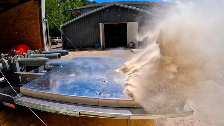
Air cannons are a mission-critical cleaning device for nearly all cement plants. Their cleaning power depends upon the effective supply of compressed air. Therefore, compressed air is a mission-critical power source for nearly all cement plants.
As referenced in a previous edition of WorldCement, Paul Edwards described compressed air as, “likely the most inefficient source of power in the facility.”1 He identified leaking air cannons (which sometimes consumed 40x their projected air consumption) as a major source of waste. Furthermore, leaking air cannons clean poorly because they often fail to reach sufficient air pressure.
Most plants underestimate the financial impact of leaking air cannons. These leaks waste hundreds of thousands of dollars in compressed air and dramatically increases operational and maintenance costs due to poor cleaning. Leaking air cannons represent a million-dollar problem.
There is, however, a better way. With three simple steps, Dracyon can economise air consumption and increase cleaning efficiency. The result is millions of dollars in ROI.
Step 1: increase the volume
The first step may seem counterintuitive. Economise air consumption by increasing the size of the air tank? Yes.
The first task of any air cannon must be to clean effectively. Many air cannons fail because their air tank is too small. Air stored in the tank is energy. A larger tank increases the kinetic energy and momentum of every discharge. Countless tests have confirmed that larger tanks clean more than smaller tanks.

Before considering how to reduce air leakage, plants must ensure they have enough air in the tank! Larger tanks do not increase air leakage. Therefore, they do not increase wasted air. There is, however,
more to consider. Since larger tanks apply more energy to every discharge, they increase cleaning without increasing air consumption. In fact, they use compressed air more efficiently for the following reasons:
f Increased cleaning energy means fewer discharges are needed. The more powerful blast often reduces the total number of discharge points by as much as 50%. In the article, Edwards claimed that one leaking air cannon consumed as much air as 40.1 20 leaking air cannons would consume as much air as 800!
f Improved technology requires fewer air tanks. Dracyon’s multiplier system supplies air to multiple discharge points with only one tank. With fewer tanks to maintain, maintenance personnel are less likely to leave leaking cannons unaddressed.
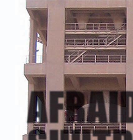
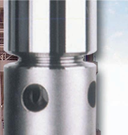
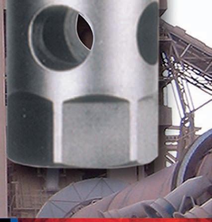
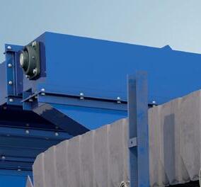
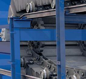
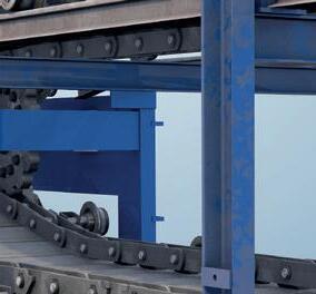
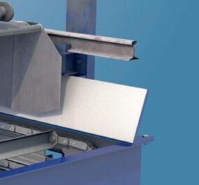
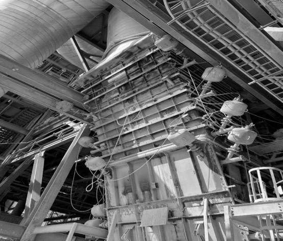
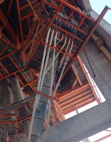
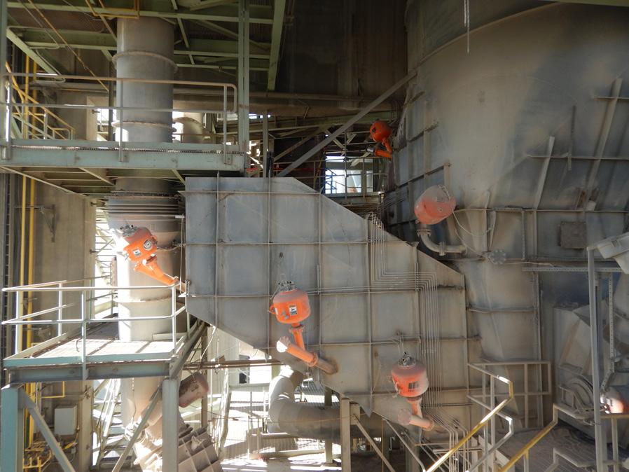
f Increased tank size enables superior installation practices. Smaller tanks must be installed very close to the discharge point because long pipe runs reduce their cleaning power. They are often installed in places that are inaccessible for safe and regular maintenance, as shown in Figure 3. If any of those tanks were leaking, it would be difficult to apply online maintenance. Larger tanks, by contrast, can clean effectively with long pipe runs, enabling plants to install them in easily accessible areas. Cleaning efficiency is directly correlated to reliability. When air cannons are easily accessible for regular maintenance, they are more reliable and, therefore, more effective. It does not matter how effective an air cannon is if it does not work!
Though it may seem counterintuitive, larger tanks are the first step to economising air consumption and increasing cleaning efficiency. It all starts with the increase in cleaning energy. This enables plants to clean with fewer discharges, extended pipe runs, and superior installation practices, all while dramatically increasing material movement.
Step one may have been a bit counterintuitive, but step two is just common sense. The prevailing practice in the cement industry is to refill the air cannon immediately after its discharge. This practice stores air and maximises wasted air through leaks. It is irresponsible due to safety concerns and financial waste:
f It is a legitimate safety concern. As a pressurised vessel, air cannons do pose the risk of propelling themselves off the mounting hardware, striking someone, and causing a fatal injury (this has occurred). Given the risk, pressurising the air cannon for the longest time possible is irresponsible.
f It is a financial drain. Filling up a leaky air cannon is akin to pouring water into a holey bucket.


No wonder one leaky air cannon uses as much air as forty! Given the waste of compressed air, pressurising the air cannon for the longest time possible is irresponsible.
The common sense solution to this problem is simple. Instead of filling the tank immediately after discharge, fill it immediately before discharge. Fill and fire. It solves both problems mentioned above:
f It is a safer practice. A non-pressurised air cannon poses no risk propelling itself off the mounting hardware. By filling just before discharge, the possibility of when that could happen is minimised. If an air cannon discharges
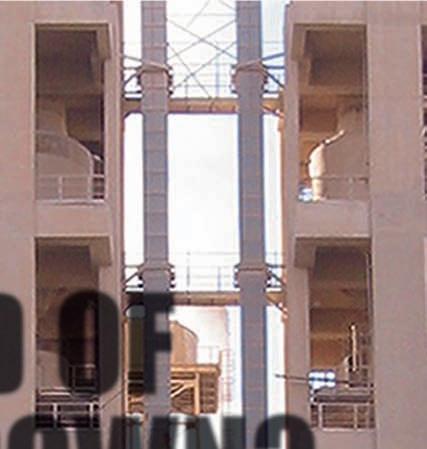
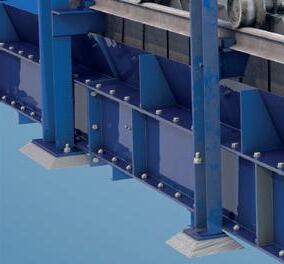
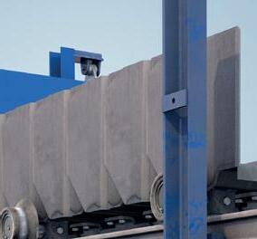
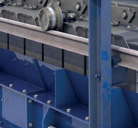
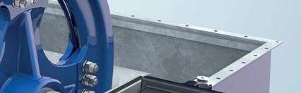
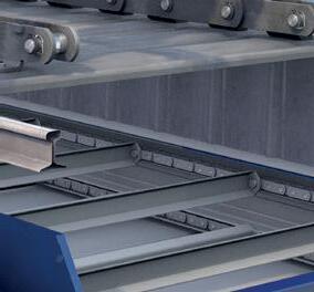
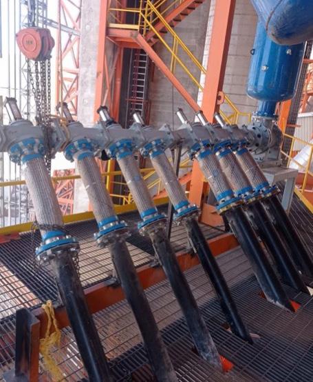
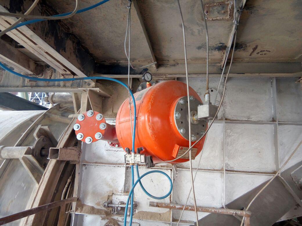
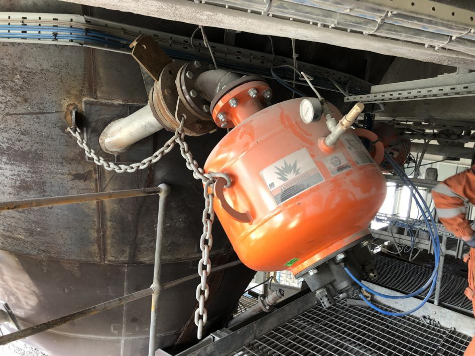
4. Despite the long pipe run, this installation cleaned more effectively than previous air cannons. It did so with far fewer reservoir tanks, all of which were easily accessible to maintenance personnel.
every 15 min. and takes 15 sec. to fill, the safety implications of the two practices are as follows:
» Prevailing practice: the air cannon is pressurised for 14 minutes and 45 seconds.
» Fill and fire: the air cannon is pressurised for about 15 seconds.
f It is a shrewd financial practice. Even if an air cannon is leaking, filling and firing reduces the wasted air to nearly zero. Leaking air cannons consume far more air than what is required for a discharge. On a fill and fire system, it would be impossible for one air cannon to use as much air as forty.
It is not a matter of if the air cannon will leak, but when it will leak. All air cannons will leak. The fill and fire technique recognises that reality and minimises safety risk and financial loss in light of it. The result is a safer plant and more economic use of compressed air.
The final step toward economising air consumption and increasing cleaning is to customise the blast. For many years air cannons came with a universal recommendation. Install a fan jet nozzle to discharge every five to ten minutes. That worked for some applications but not all. Each installation should have a customised nozzle recommendation and discharge cycle.
Many plants employ outdated nozzle technology that is unable to meet today’s challenges. Modern nozzles are more effective, more durable, and more affordable. The improvements are so drastic that Dracyon offers a 10-year warranty on its air cannon system, including a 3-year guarantee on the life of the nozzle.
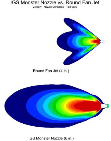
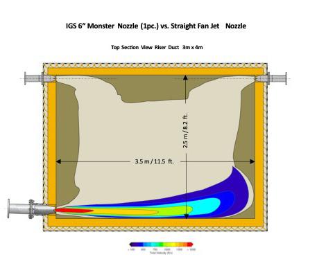
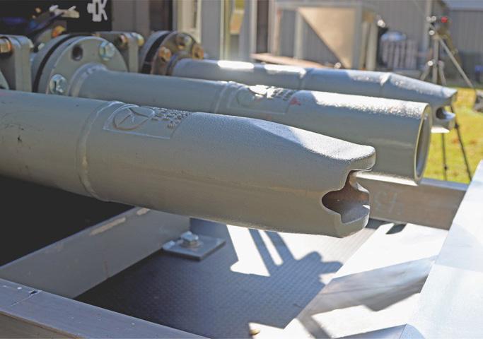
f Finding the right nozzle. One of the challenges to today’s cement industry is the increase of alternative fuel sources which produce difficult buildup. The fan jet nozzle is designed to produce a wide blast over a large surface area. This blast design sacrifices an important factor of cleaning power: velocity. The nozzle supplied by Dracyon, by contrast, has a larger opening (6 in. vs. 4 in.) and produces a more concentrated, high velocity discharge. It is far more adept for applications with difficult buildup or those requiring deep penetration. f Choosing the right discharge cycle. Once the correct nozzle has been selected, the question is, how often should it discharge? Although the standard answer is once every five to ten minutes, that is often inadequate and reveals a lack of process knowledge. Before determining a discharge cycle, the following questions need to be answered:
» What is the fuel source and nature of the buildup?
» What is the rate of buildup in the area before the air cannon?
» What is the needed depth of cleaning in the application?
Those answers will vary for many applications, hence the need for a customised discharge cycle. That said, most applications would benefit by reducing the frequency of their discharge. This enables the buildup to properly accumulate and adhere, which, when the air cannon has sufficient power, yields more material movement. It also leads to lower air consumption and reduced maintenance.
The 'one size fits all' approach to nozzles and discharge cycles has often led to wasted air and poor cleaning. Dracyon’s approach of customising the blast means fitting each air cannon with the right nozzle and discharge cycle. Some installations would benefit from two, back-to-back discharges every twenty minutes, whereas others would require one discharge every ten minutes. Some installations are poorly served by fan jet nozzles, whereas others benefit from them. There are countless variables. Dracyon’s family of air cannons and nozzles, together with extensive experience in cement plants all over the world, make it uniquely equipped to customise the blast. A customised recommendation is a simple way for plants to economise air consumption and increase cleaning efficiency.
Compressed air is likely the most inefficient source of power in the plant. Air cannons, which are a mission-critical cleaning device, are one of the biggest sources of waste. Even worse, many of them do not clean effectively. Leaking air cannons is a million-dollar problem.
But Dracyon’s three step plan (increase the tank, fill and fire, and customise the blast) is scientifically proven to economise air consumption and increase cleaning efficiency. Leaking air cannons is a million-dollar problem, but the three step plan is a million-dollar solution.
Less than 1 month after switching to LE’s kiln lubricant, a cement company reduced its lube consumption by 7 times, achieving approximate annual savings of $63K for a single kiln. At the same time, gear temperatures dropped and maintenance time decreased.


As far back as the 1970s, cement plants in Europe and the US were blending traditional fossil fuels with shredded tyres and waste from timber production. Indeed, the cement sector was one of the first to explore waste feedstocks as effective alternatives to coal and pet coke.
Recently, with fuel accounting for a rising percentage of cement clinker production costs, more and more producers have sought to secure suitable waste streams – for use both as fuel and in their raw feed mix – to achieve cost-effective production that is also recognised as being more sustainable.
Indeed, a handful of cement plants around the globe are able to boast 100% alternative fuels (AFs), raising the bar for the sector and challenging fossil fuel-reliant plants to look to locally available wastes as fuel sources – from non-recyclable plastics, commercial mixed wastes, and shredded upholstery to biomass like rice husks, sugar cane bagasse, and pelletised animal meal.
The choice of AFs requires careful consideration as the implications for productivity and process design can be significant. One of the major differences between solid fossil fuels and waste-derived alternatives is the way they flow through the process, typically determined by their physical properties and moisture content.
Efficient and continuous material flow is a critical element of dry-process cement manufacture, so any accumulation or blockages can choke productivity and profitability. Hang-ups in storage systems and build-ups in chutes and process vessels can cause serious obstructions that impede equipment performance and reduce efficiency.
Material build-up can occur in many places in the plant, and in several forms. Accumulation often occurs in riser ducts, feed pipes, cyclones, transfer chutes, and storage bins, as well as kilns and coolers. In extreme cases, massive buildups can suddenly break loose and suffocate the process, potentially causing significant damage to equipment and
almost invariably prompting the need for unscheduled downtime.
It is worth stating that buildups of AF materials can happen even in well-designed systems. Changes in process conditions, the raw materials themselves or even the weather can have an effect on material flow, and a small amount of accumulation can quickly grow into a serious blockage, with obstructions often leading to secondary problems.
Accumulations of some AFs are even susceptible to spontaneous combustion, while others may accelerate wear, tear, and corrosion of structures, and deterioration of conveyor components. A preventive approach to controlling buildups and blockages is the only way to address these issues and prevent unscheduled downtime.
Lost production is usually the primary cost of flow problems, but the expense can become apparent in a variety of secondary ways. Shutdowns to clear blockages and buildup also cost valuable process time and maintenance hours. That increases maintenance costs and diverts service teams away from core activities, potentially introducing needless safety risks. Refractory walls can become worn or damaged by tools or cleaning techniques. When access is difficult, removing material blockages may also introduce serious risks for personnel. Working platforms are usually needed to reach access points, and there is a risk of exposure to hot debris, dust, or gases when chunks of material stuck to the sides of a silo, hopper, or bin are suddenly released. If the discharge door is in the open position, material can suddenly evacuate, causing unsecured workers to get caught in the flow. Cleaning vessels containing combustible dust – without proper testing, ventilation, and safety measures – could even result in a deadly explosion with as little as a spark from a shovel.
Many of the most common problem areas for accumulation are also classified as confined spaces, requiring a special permit for workers to enter. The consequences for untrained or inexperienced staff can be serious, including physical injury, burial, and asphyxiation.
The most effective way to manage the challenges of using AFs is to design the material handling system around the physical properties of the intended fuel. That means each component is specified and engineered according to the flow characteristics of the material.
In reality, most cement producers will be using existing systems to feed in AFs, which can require some modest retrofitting or a whole new facility. Martin Engineering has been perfecting material handling technologies in sectors like cement for more than 75 years and there are few challenges that Martin technicians have not already faced and overcome around the world.
One approach that brings significant benefits to operators seeking to retrofit material handling systems to accommodate AFs is to use modular components that can be specifically built to handle the cargo (such as transfer chutes with specific flow angles or settling zones of appropriate height and length). Rather than replacing large sections of existing equipment,
modular designs can be engineered to fit into the specific system on hand.
However, Martin’s engineers are also experienced enough to know that designing a single system to handle every type of AF is virtually impossible. Materials with high moisture content can adhere to chute or vessel walls or even freeze during winter temperatures. Continuous operation can compress the material, and physical properties often change due to natural and inevitable variations that are typical in waste-derived fuels. Just a small change can cause a system to become completely blocked in a short amount of time. Most of these issues can be overcome, and a whole-process approach is needed with a selection of flow aids installed to collectively work together to keep things moving.
One of the first challenges to be addressed when using dry AFs is the potential for release of combustible dust, and containment is therefore critical. Successful dust management starts with minimising air turbulence through appropriate transfer point geometry.
Air is very compressible and will find the path of least resistance. Typically, the design of transfer points means that air is most often speeding up to flow under or around a single exit dust curtain with narrow slits, resulting in re-entraining the dust particles in the exhaust. Therefore, it is necessary to create recirculation regions inside a transfer point to improve dust settling and containment.
A transfer point is similar to a gravity settling chamber, which depends on relatively slow air speed without much turbulence. Conversely, the airflow through a conveyor transfer point is almost always turbulent. So, the transfer point enclosure design needs to incorporate a series of curtains to slow and control airflow and promote settling. Used in tandem with adjustable dual skirting, these can create a sealed environment where dust settles back into the cargo flow or is sequestered into a dust bag without spillage or emissions.
To achieve contained and consistent flow on conveyors handling large volumes of AFs, transfer chutes and vessels must be designed to accommodate and facilitate the flow of the materials they will be handling. Even if the operating conditions are expected to be ideal, many engineers include flow aid devices in new designs to ensure delivery of the optimum results but with the agility to deal with changes in AFs and raw materials.

Flow aids is an umbrella term for a complementary set of components installed to promote the transport of materials through an entire system. Because they will affect a conveyor’s loading, flow aid devices can also reduce spillage and help control dust. If not properly managed, buildups that break free – accidentally or intentionally – can produce surges, which result in overloading, spillage, and belt mistracking. By designing active flow aids
into a conveying system, the operation gains a level of control over the material that cannot be obtained with static approaches (such as low-friction liners) alone.
Flow aids come in a variety of forms, including rotary and linear vibrators, high- and low-pressure air cannons and aeration devices, as well as low-friction linings and special chute designs to promote the efficient flow of bulk materials. These systems can be combined in any number of ways to complement one another and are shown to improve performance. They can be as simple as an impacting piston vibrator on a chute wall to dislodge material buildup, or as sophisticated as a multiple air cannon system discharging automatically on a timed cycle to prevent accumulation. The components can be used together to benefit processing of virtually any bulk AF, or hazardous or complex materials.
One proven device for resolving material flow issues is the Martin® Air Cannon, which has a number of applications in cement production, from unclogging cyclone collectors and kiln inlets to keeping super-heated material moving through the cooling process. Air cannons function by releasing a powerful, targeted shot of pressurised air from a tank through a short pipe assembly to a specialised nozzle, breaking away collected material from inner surfaces and directing it back into the process stream.
Recent innovations in the design, engineering, assembly, and installation of air cannons have been particularly effective in maintaining safe, efficient flow in cement operations. Today, these devices are relatively compact and lightweight, with efficient and powerful performance. New tank designs range from 35 L to 150 L capacity, and deliver more force output with less air consumption at half the size of older designs. The way they are built, installed, serviced, and powered is all geared towards maximising production and reducing both downtime and the overall cost of operation, while contributing to better safety.
Air cannons often eliminate the need for confined space entry to remove buildup. Martin air cannons are designed to discharge only with a positive pressure pilot signal to reduce the chance of accidental compressed air release.
Bringing cement production equipment up to operating temperature takes a tremendous amount of energy. The cost of downtime for cooling the system, performing maintenance work, and reheating the kiln can be prohibitive. So modern air cannons are designed to be easily serviced from outside as individual units, for example Martin’s Y-pipe assembly can be
maintained without shutting down production. And to avoid the need for tank removal and confined space entry, engineers have designed new cannons with outward-facing valves. This provides safe, easy access by a single maintenance worker from outside the vessel.
That innovation is one of a number of flow aid accessories that can be installed to achieve even better performance. For example, Martin’s SMART™ Series High-Temperature Nozzle enables hassle-free air cannon maintenance as it is safe and easy to service and replace without damaging the surrounding refractory. Then there is the Thermo Safety Shield which protects workers against exposure to extreme heat, allowing safe and timely servicing of air cannon systems.
Not only does advanced engineering mean that the servicing of air cannons can take place without the need to stop production, but Martin recently launched a patented technology that even enables them to be fully installed without a process shutdown. This system allows specially-trained technicians to mount the units on furnaces, preheaters, coolers, and other high-temperature locations while production continues uninterrupted. Specialised core drill bits are engineered to create the exact diameter hole at the precise angle needed.
Once a core is safely installed in the vessel wall, an isolation gate is inserted to protect from heat and blowback. Trained technicians then attach the Y-pipe assembly with no downtime or process disruption. The technology dramatically reduces expensive downtime associated with traditional installation methods, which require that high-heat processes be halted to allow core drilling and mounting of the cannons.
The use of use alternative, waste-derived fuels, and raw materials does present challenges due to their composition and characteristics. Yet those challenges can be overcome with the support of bulk material handling specialists, who are able to identify existing and potential problems and their root causes, and design complete systems that prevent buildup and avert the knock-on effects for production. Making good use of waste, either as fuel or as raw material, is cost-effective and environmentally sound. Coupled with the expertise to develop effective handling solutions, operators can be sure to maintain the highest levels of safety, efficiency, and productivity.
Breedon's Hope Works is the UK’s largest cement plant, producing more than 1.5 million tpy from twin dry process kiln lines. The plant has also been a leader in using a range of waste-derived fuels and alternative raw materials.
The mixed properties of the raw meal and AFs going into the plant have increasingly presented challenges of hard build-ups caused by sticky materials accumulating in cyclones, hoppers, and bends in the process, resulting in reduced and unstable flow.
A major plant upgrade in 2015 aimed at increasing the use of waste derived fuels involved modifying the kiln inlets, riser sections, and cyclones. The team turned to Martin for 30 Tornado Air Cannons in the kiln inlet – fitted and maintained by Hope’s expert in-house team. Then in 2018, when planning a further upgrade, Martin Hurricane Air Cannons were specified throughout, from the first stage cyclones right through to the clinker cooler.
Hurricanes feature a positive-acting valve that provides greater force, uses less air, simplifies installation and makes for easier, safer maintenance. The risk of accidental discharge is eliminated, and the control solenoid can be placed away from harsh conditions so it is easier to access.
Breedon fitted the first Hurricanes in 2019 and the benefits were clear. That led to further installations in all cyclone stages, kiln inlets, burner pipes, clinker cooler, and coal feed hopper. By 2022 there were 140 Hurricanes installed, all with 70 L tanks and positive-acting valves.
The two burner pipe air cannons use a 150 L tank for maximum power to clear the 'rhino’s horn' build-up at the tips. The Hurricane arrays can handle the frequent firing required to keep things clean, and the high pressure air system is monitored centrally so the team can track performance. Knowing the risk of build-ups and blockages is being controlled, the team is now further diversifying its raw meal and fuel mixes.
Alan Highton began his career as a qualified millwright, after receiving his N6 National Certificate in mechanical engineering in South Africa. Highton joined Martin Engineering in 1996 as a service technician and was promoted to a sales position in 1999. Alan was named the RSA sales manager in 2006, and in 2012, was promoted to North American sales manager. He currently serves as the North American sales manager for Martin Engineering's Wear Components division.
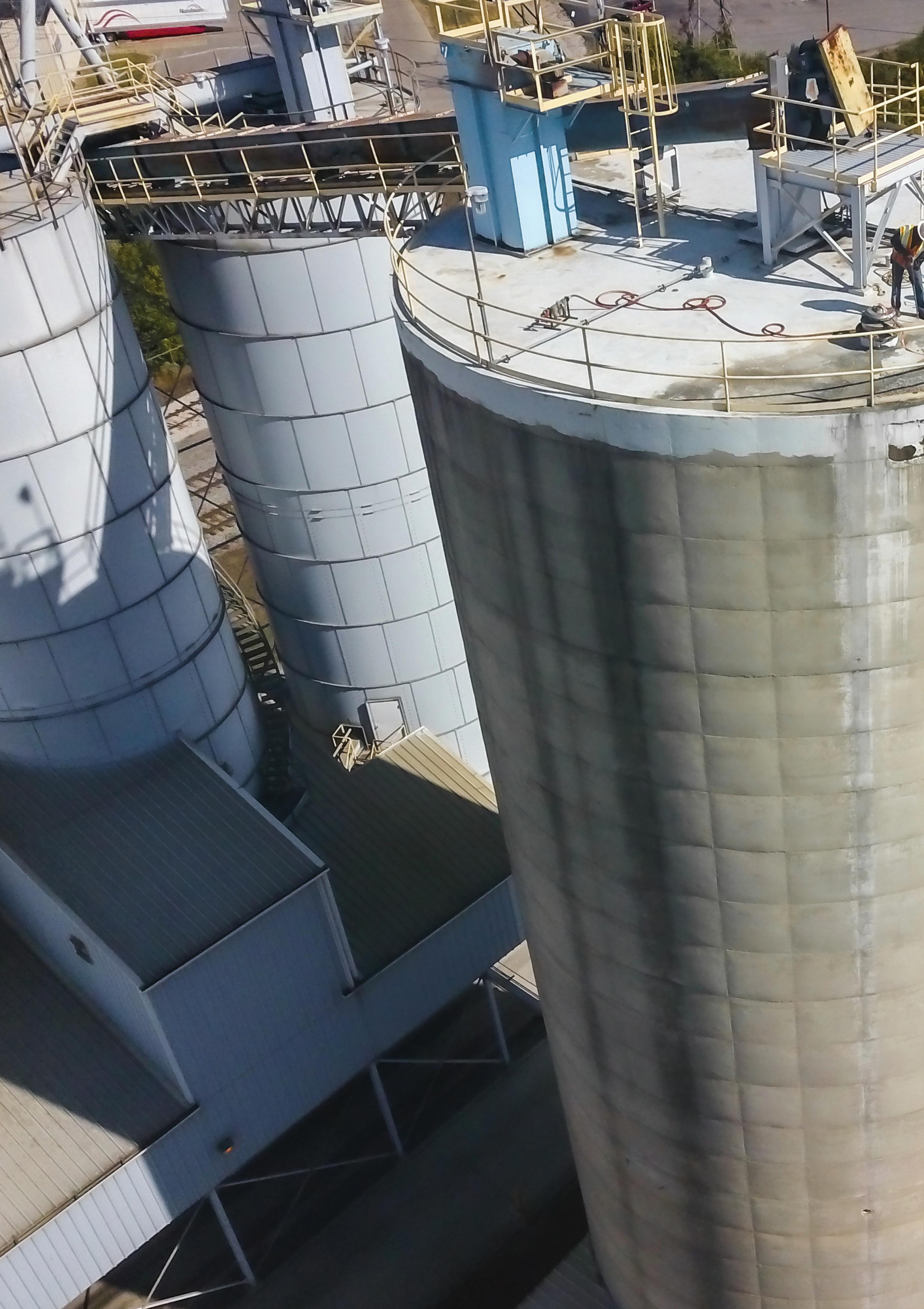
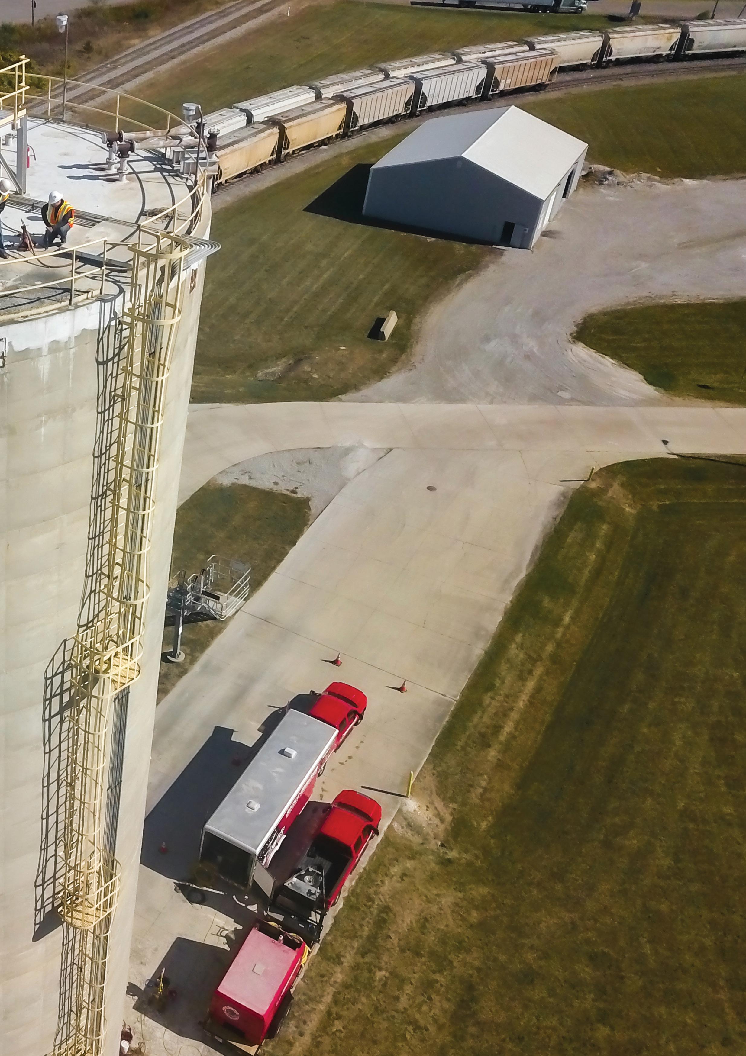
Kearsten Huffman, Mole•Master Services Corporation, highlights the importance of proactive cement silo cleanout and inspection to prevent costly downtime, improve storage capacity, and ensure operational safety.
The professional cleanout and inspection of cement silos and storage bins can help maximise their operating capacity and minimise downtime. Many cement producers often find themselves so focused on meeting ever-increasing demand and maintaining uninterrupted production that they lose sight of
the long-term implications of insufficient maintenance. Having to go completely offline for inspection or repairs can result in costly downtime and the loss of salvageable material. The vast difference between avoiding a
shutdown and recovering from one underscores the ROI of silo cleanout and inspection.
Year after year, cement manufacturers are faced with increasing product demands, forcing an increase in output with limited downtime allowance. The global portland cement market size is valued at approximately US$4.5 billion and is expected to reach a valuation of nearly US$7 billion by 2033. Consequently, facilities are running longer, harder, and leaner than ever before to meet these growth trends. This can lead to shortcuts, failures, and compromised safety standards. Over time, storage vessels, material transfer equipment, and discharge systems buckle under the strain. Moisture intrusion and unplanned production upsets can lead to significant material buildup, the glazing over or ripping of air pads, and the malfunction of gates, valves, and air slides. A more proactive approach can negate or minimise many of these variables.

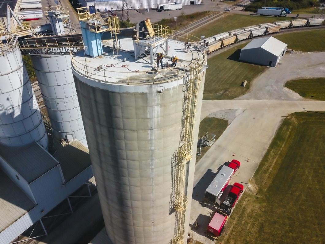
A major cement manufacturer in South Carolina opted to take a preemptive approach to avoid the detrimental effects of long-term, improperly maintained storage. Despite years of operation with no apparent major issues, the plant management introduced an initiative for the cleanout and inspection of their bulk storage vessels. Unknown variables were discussed during the project’s conception. Among these were the amount of material packed along the sidewalls and into the flat bottom silo, the integrity of the structure, and the condition of the air pad-lined bottom.
The cement processor commissioned Mole•Master Services Corporation, headquartered in Marietta, Ohio, US to complete the project. Field technicians implemented the Big•Mole system to ensure all roof and sidewall buildup was removed and dropped to the lower half of the silo for removal. This first step is vital for the following inspection to be effectively performed. Utilisation of the Big•Mole system also allows cleaning operations to be performed efficiently without confined space entry, eliminatingthe need to place a crew member inside the vessel. The silo had not undergone routine maintenance for several years and, as a result, hard, rock-like material had developed.
Large boulders had formed and were scattered around the perimeter and centre of the silo.
A significant benefit to utilising this cleaning method is the ability to aggressively break up these formed chunks and prevent their migration and eventual plugging of a discharge system. Removal of the hardened material was completed using a vacuum truck. Once material levels were brought below the lower side access, the more detailed cleaning around the existing air pads was completed, along with the evaluation of the repairs or replacement the air pads required.
The major cleaning component of the project was completed, and the silo returned to 100% capacity. Once OSHA/MSHA-compliant confined space entry standards were in place, Mole•Master technicians began the structural inspection. A comprehensive exterior and inter inspection was performed, followed up by a detailed report of all findings and suggested repairs.
This facility's foresight allowed them to avoid unplanned downtime, gain back lost storage capacity, maintain efficient production levels, and, most importantly, continue operation with the knowledge that the silo poses no structural safety risks to their personnel.
Mole•Master Services Corporation offers a wide range of cleaning and inspection services uniquely designed to handle projects of all scopes and levels of difficulty. Regularly scheduled maintenance plans or immediate-need services are available to minimise downtime and maximise safety and efficiency.
The Mole•Master proprietary equipment used for the project included:
f Big Mole™ system: used for vertical wall and roof cleaning without confined space entry.
f Safe-T-Shot™ system: carbon dioxide blasting for thick material in cones or on bottoms.
f Vacuum trucks: continuous material removal to minimise downtime.
f Hand tools: jackhammers, rock drills, and other tools for targeted material removal.
f Arch Master™: establishing a safe flow channel in otherwise bridged or plugged material.
Kearsten Huffman is the Southeast Regional Project Manager for Mole•Master Services Corporation, coordinating silo and bin cleanout storage solutions across multiple industries.
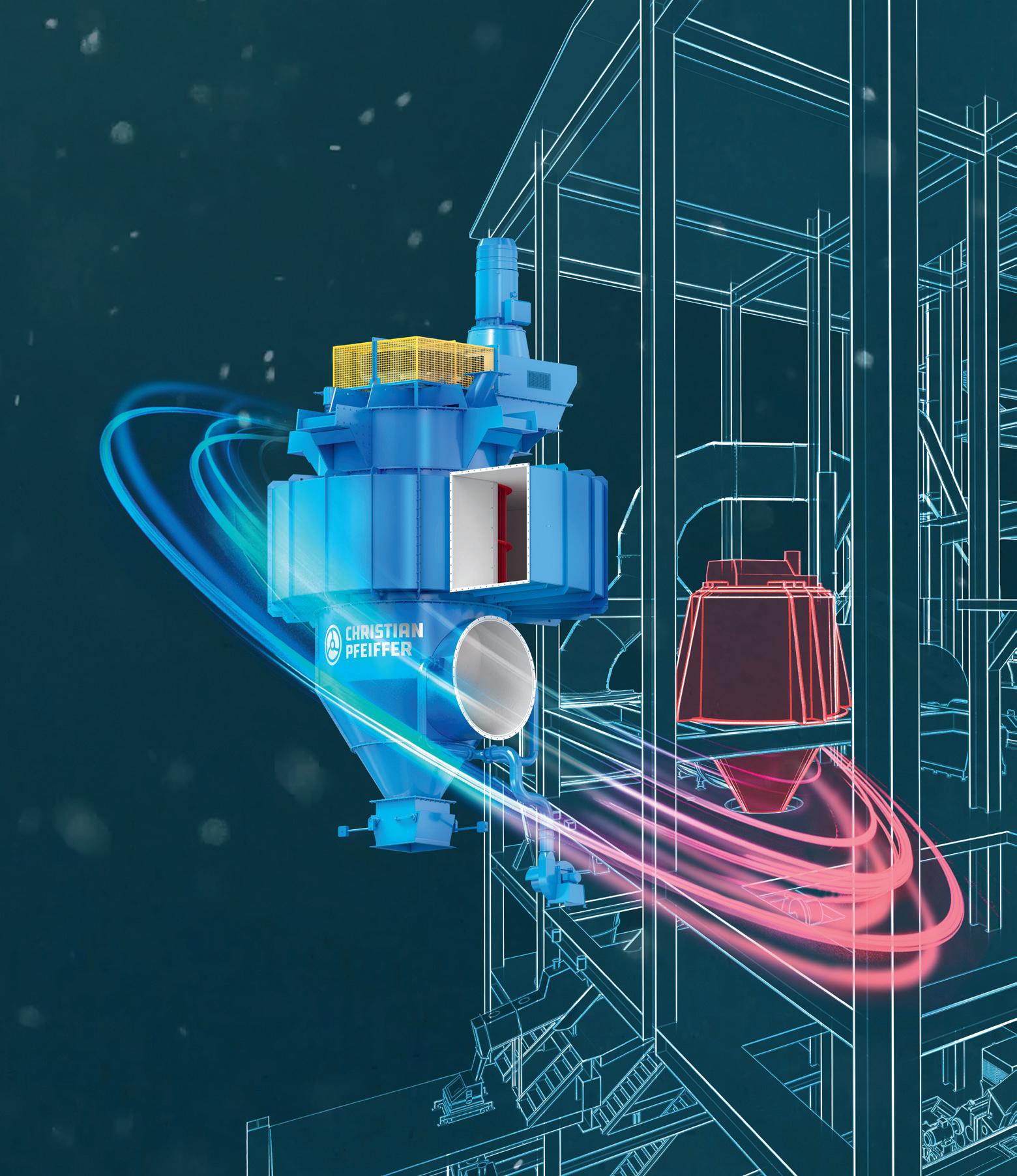
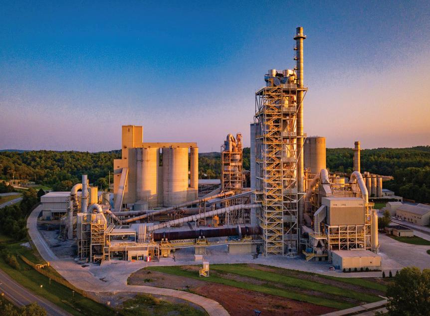
Diverse technical training, including 17 technical paper presentations and seven training module sessions
Roundtable discussions on three timely industry topics
Panel discussions on supply chain & logistics and government affairs with PCA members and staff
Keynote speaker Paul Chadwick, award-winning comic book creator of Concrete
Enhanced plant tour includes visits to National Cement Company of Alabama, Inc. (Ragland Plant) and Reworld (alternative fuel provider) May 4-8


®


Manuel Mühlbacher, Christian Pfeiffer, highlights innovations in roller press technology, focusing on enhanced reliability, simplified maintenance, and greater efficiency for raw material processing.
The production of raw materials requires energy-intensive comminution processes, which have a significant impact on operating costs and the environmental footprint of industrial plants. Raw material processing, in particular, presents a challenge, as high-pressure forces are needed to ensure efficient grinding while minimising wear and energy consumption. Advanced solutions are essential to enhance efficiency and extend the lifespan of equipment.
An innovative response to these challenges is the newly developed ROP roller press, which leverages cutting-edge technology to optimise the comminution process. With a strong focus on durability, energy efficiency, and intelligent control systems, it sets new benchmarks in industrial grinding technology.
Christian Pfeiffer provides a comprehensive performance package that includes all components necessary for smooth installation and long-term operation. This package includes a robust pre-bin with a capacity of up to 90 sec. of material feed, shut-off gates, an intelligently designed feed chute with dual gates for precise material flow control, and specially hardened rollers with a unique layered structure engineered to handle extreme loads. For easy maintenance, the ROP is equipped with a maintenance platform, and unique maintenance solutions ensure reliable long-term operation, even under challenging conditions. Additionally, Christian Pfeiffer offers various drive options to meet different voltage and frequency requirements, including variable-speed low-voltage motors (400/690 V) or variable-speed medium-voltage motors (4.16/6.0/6.6 kV), each designed to maximise the ROP's efficiency.
Pre-bin system for optimised material feed
Mounted on the plant’s steel structure, the pre-bin ensures a constant material feed, with the fill level monitored by precise load cells in combination with the innovative feed chute. This setup guarantees a steady comminution process without material shortages, improving process stability and productivity.
Precise control of material feed
Christian Pfeiffer’s roller press feed chute is equipped with two pairs of gates to regulate the material flow, allowing operators to adjust the comminution process in real-time. An integrated dedusting system removes excess air and dust, minimising process fluctuations and maintaining a clean working environment.
with innovative layered structure for maximum service life
The specially developed rollers consist of two components: a robust shaft and a shrink-fitted roller. The wear protection of the rollers is structured in three layers: a buffer layer to prevent cracking, a hardness
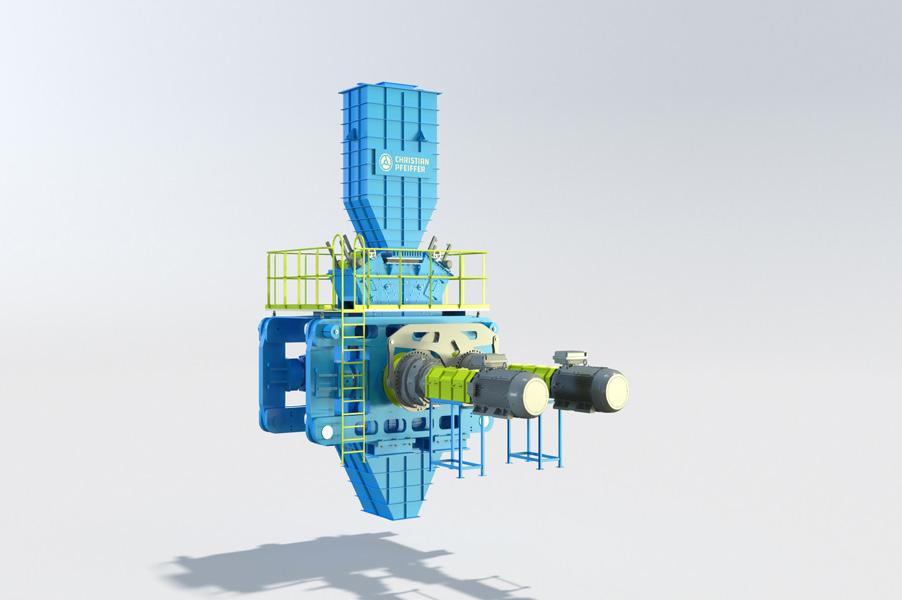
layer for strength, and a profiling layer to minimise wear from abrasive forces. This structure allows for a service life of up to 100 000 hours without welding repairs, depending on the ROP's application. Maintenance on the roller surface wear protection can be performed directly on the machine, reducing maintenance costs.
Rollers with ceramic wear protection for ore grinding
These specially designed rollers consist of a robust shaft and a shrink-fitted sleeve. Wear protection is ensured through ceramic inserts, achieving a service life of up to 10 000 hours, depending on the ROP’s application. Maintenance of the ceramic wear protection is performed with the rollers removed, requiring a second set of rollers to be kept on stock for continued processing. The ROP's design allows for a quick and seamless roller pair exchange.
Advanced bearing design for maximum operational safety
ROP models with a pressing force of approximately 9000 kN or higher are equipped with cylindrical roller bearings. Specialised guide elements in the bearing housings compensate for roller skewing, ensuring precise axial alignment of the rollers. Smaller ROP models are fitted with self-aligning bearings, reducing space requirements and costs. A revolutionary axial guidance system with chrome-plated guide rails and Teflon sliding surfaces facilitates maintenance and minimises operational interruptions.
Oil circulation lubrication system for longer service life and efficient cooling
An integrated oil circulation system continuously filters the lubricant oil, removing contaminants to extend bearing life. The circulating oil effectively dissipates the heat generated during the comminution process, eliminating the need for additional cooling bores in the roller shaft.
Cheek plates for durable protection and easy maintenance
The lateral roller surfaces are enclosed with cheeks plates featuring wear protection. These cheek plates are flexibly mounted, adapting to roller movements and alignment to provide consistent lateral sealing. The design enables easy removal of the cheek plates without requiring additional cover dismantling.
Stable machine frame design with maintenance friendliness at the core
Christian Pfeiffer designed the ROP frame to deliver high stability with reduced weight and maximum user-friendliness. Large openings in the frame facilitate inspection of critical components, enabling early wear detection and timely maintenance planning.
The ROP is equipped with a hydraulic pressure system that transfers the necessary pressing force to the movable roller through two hydraulic cylinders. These cylinders are mounted on pivot bearings to flexibly follow the movements of the roller.
The drive of the ROP is based on a powerful system with planetary gears and safety couplings designed for reliable torque transmission. The drive is protected by a safety coupling that regulates the inertial torque during load changes and prevents overloads. Additionally, a driveshaft provides the necessary flexibility, ensuring that the motor remains free of load, and the machine is easily accessible for maintenance. Optionally, a hydraulic coupling can be chosen for quick and maintenance-friendly installation.
Thanks to an advanced control system, the ROP is almost fully automatic. The control system handles a variety of complex monitoring and control tasks and responds to changes in material flow. The main functions include:
f Monitoring of all sensors.
f Automatic pressure and gap control using two-way cylinders.
f Feed chute control.
f Misalignment monitoring of the movable roller.
f Master-slave control for torque and speed management.
f Level monitoring of the pre-bin.
f Temperature monitoring of bearings and gears.

f Vibration monitoring for preventive maintenance.
The control system can be integrated either as a standalone system or as a software component into the existing plant control system, allowing for flexible adaptation to the customer's requirements.
For safe and efficient maintenance, Christian Pfeiffer provides a selection of specialised tools, including lifting tools and transport devices for the rollers, including bearings, gauges for wear measurement, and transport equipment for hydraulic cylinders. These tools ensure safe handling and significantly facilitate maintenance work, resulting in increased uptime and thus higher availability of the plant.
Christian Pfeiffer’s new ROP roller press is a step forward in industrial comminution technology. With a strong focus on durability, ease of maintenance, and intelligent control, it offers a solution suitable for a wide range of industrial applications and can be flexibly adapted to the specific requirements of customers.
No hazardous human entry of raw material or finished cement silos.
Return your silo to 100% of planned storage capacity.
Eliminate obstructed silo discharge points to facilitate proper material flow.
Innovative cleaning methods get silos back into production quickly.
07/24 02921


Mike Stanzel & Oliver
Sohn, Chryso North America, present a multilayered approach to maximising blended cement performance for use in concrete.
The landscape of cement manufacturing is evolving, driven by the need for more sustainable and lower embodied carbon construction materials. The introduction of blended cements, incorporating supplementary cementitious materials (SCMs), including finely ground limestone, has presented challenges for many cement producers. These challenges include reduced strength, leading to increased Blaine specific surface area (BSSA) and lower production rates, and subsequent field performance issues, such as higher water demand, reduced bleeding rates, plastic shrinkage cracking, and changes in set-times. These factors have led to some reluctance in certain markets to fully adopt these new materials.
While advanced grinding additives have helped regain some of the lost performance and production capacity, a more comprehensive approach is necessary to fully recover the desired performance and production levels of traditional ordinary portland
cement (OPC). One must address the four critical levers essential for optimising blended cements to match traditional OPC expectations: proper clinker formation, mill optimisation, effective additive selection, and optimising quality targets (Figure 1).
By addressing all four key areas, cement producers can overcome the challenges associated with blended cements and achieve the performance and sustainability goals required in today's construction environment. Only by satisfying all four levers can the desired performance be achieved and sustained, ensuring that blended cements can meet modern needs without compromising on quality or efficiency.
Clinker is the primary intermediate product in cement manufacturing, and its quality directly impacts the potential performance on the
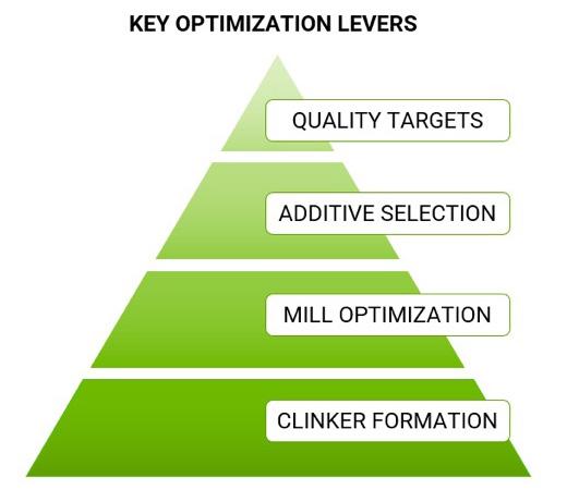
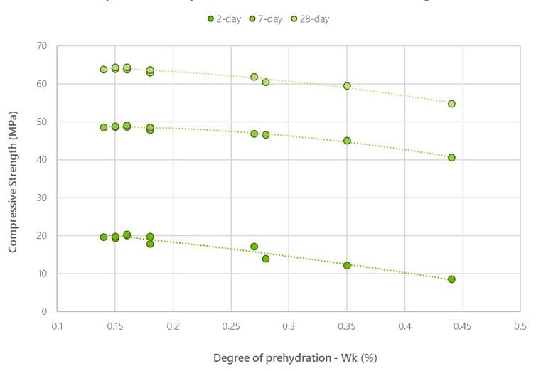
final cement. Producing high-quality clinker consistently is a significant step to reducing emissions through supplementary material use, while meeting construction demands in the field. This involves careful control of:
f Chemical composition: particularly alite content, aluminate content, liquid phase to ensure good combinability, and a proper alkali-sulfur balance to avoid inhibiting C3S formation and cycling of the system.1
f Raw milling parameters: particularly kiln feed uniformity and sufficient target fineness to avoid free-lime and belite clustering.
f Burning and cooling conditions: ensuring oxidising conditions, proper burner alignment, rapid heating and cooling, and proper clinker density.
All of this not only impacts cement performance, but also clinker grindability, which is key to optimising combined particle size distributions of inter-ground blended cements.
While grinding additives can help address quality and process issues, they are most effective when the clinker quality is high to begin with. Quite simply, the better the clinker, the better the synergy with additives, the better the cement, and the happier the contractor out in the field.
Mill maintenance and optimisation is a critical area that often does not receive enough attention and budget allotment. Over the past two years, Chryso has conducted in excess of 350 mill audits globally, and identified several recurring issues. While chemical additives have proven to work even when a process is sub-optimal, minor operational adjustments and proper maintenance can result in significant improvements to both cement quality and mill output.
One of the more common deficiencies found in ball mill circuits is in achieving the designed airflow of 1 – 1.5 m/s over the charge, dependent on the mill geometry. Sufficient airflow is necessary both for ensuring adequate material transport through the mill and removal of fines, and for providing sufficient cooling. Although airflow measurements taken near the fan may often appear adequate, they do not always account for false air, which can be as high as 40% in sub-optimal systems. This air flow loss may necessitate the use of higher volumes of cooling water,
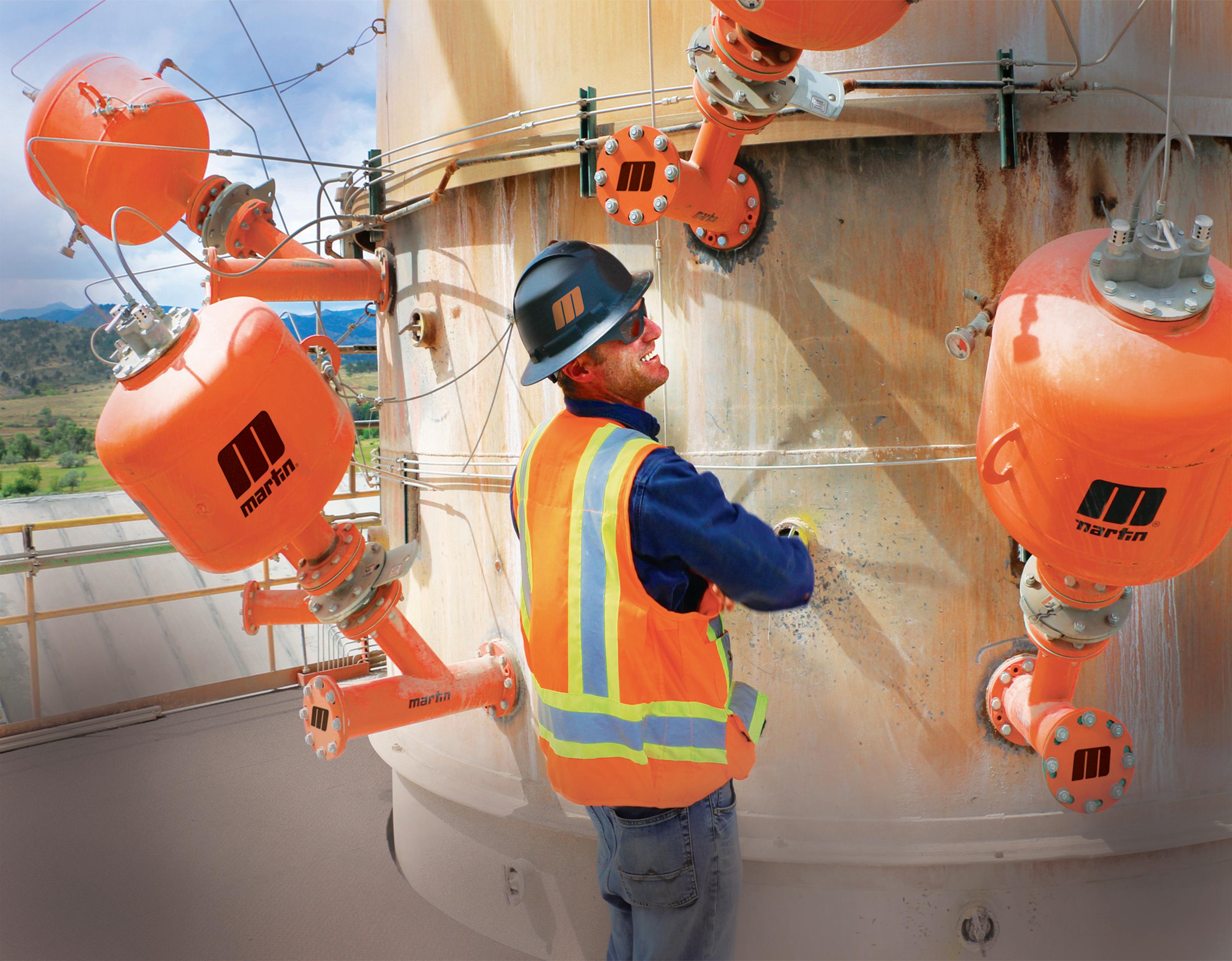
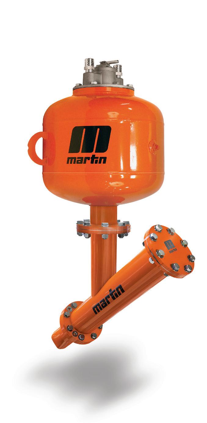
When bulk material stops moving due to buildup or clogging inside kilns, preheater towers, silos, and transfer chutes, serious consequences can multiply very rapidly.
Martin Air Cannons use the power of compressed air to help keep material flowing throughout your facility. These high-performance systems with innovative valve designs deliver precisely targeted air blasts, effectively handling even the wettest, stickiest materials.
Trusted by industry leaders worldwide, Martin air cannons eliminate most manual cleanings, reduce workplace hazards, avoid work slowdowns, and maximize production.
Don't get jammed up From emergency installations to custom solutions, Martin responds to your specific needs — maintaining throughput, improving safety, and reducing operating costs.
increasing the internal mill moisture. Combined with the moisture content of raw materials, this can increase the internal dew point, potentially leading to cement pre-hydration, which has negative effects on cement strength (Figure 2).
Elevated heat and moisture levels also increase the agglomeration tendency inside the mill, further reducing efficiency and often leading to increased usage of grinding aids to counteract the effects.
The mill ball charge is another critical factor in achieving an optimal grind. Many mills still use the same media design that was used for grinding OPC. However, the design needs to be adapted to optimise the circulating load for both the desired product performance and the mill circuit. This involves evaluation of both axial and circuit samples and often improves with finer charges and higher airflow to maintain proper filling degree and material transport. In many cases, a high degree of deformed scrap material was found within the charge and diaphragm slots,
indicating that sorting frequencies needed to be increased and functional nib-traps installed.
Separator efficiency is key to ensuring a tight particle size distribution of the product and a low bypass of product back to the mill. Tromp curves should be run routinely to monitor performance and internal inspections conducted looking for signs of wear. In most cases, inefficiencies arise from low airflow, false air, or poor feed distribution, where the air-to-solids ratio is the primary driver of classification efficiency.
In one such case, a producer in North America was able to increase their production by nearly 5% by increasing their fan speed, replacing the mill outlet seal, and removing scrap material from the diaphragm. This resulted in over a 20% increase in mill airflow, which effectively reduced the cooling water usage by over 50% and the internal dewpoint from 67˚C to 58˚C, reducing the degree of prehydration to more tolerable levels (Table 1).
One final benefit from the inspection of the mill circuits by experienced external engineers that is often overlooked is the reassurance that can be obtained by being told the mill system is already well optimised. It is not uncommon that the plant staff are good at their jobs and confirmation of this by an external agency is always welcome.
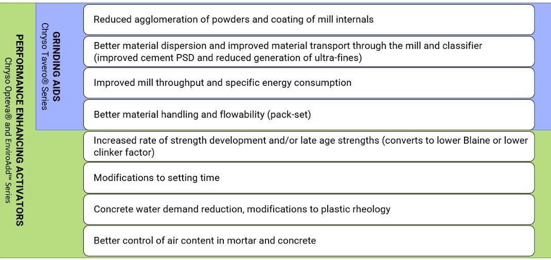
Figure 3. Traditional grinding aids reduce powder agglomeration tendencies and dispersion, improving mill throughput and specific energy consumption. Cement activators contain those same benefits but can be tailored to improve strength development or adjust other parameters important to field performance.
Once the producer has optimised the clinker and milling conditions, a high-performance additive can be much more effective at improving cement and mill performance. While traditional grinding aids improve powder dispersion and milling efficiency, activators can be tailored to a specific cement to augment various performance parameters (Figure 3), which can then be leveraged into further value for the cement producer. Depending on the desired performance characteristics, a cement additive may contain several chemical components, including tertiary alkanolamines, retarders, or accelerators, which dissolve into the mix water during concrete production, altering the hydration process.2 They can increase the degree of hydration, improve the morphology of hydration products, and enhance pore size distribution, leading to higher strength. In summary, optimising clinker and milling conditions, combined with the appropriate use of cement additives, can significantly enhance cement performance, production efficiency, and overall quality. In addition to
Reduce your CO 2 emissions with
calcined clay and grinding
C/CLAY is part of LOESCHE’s
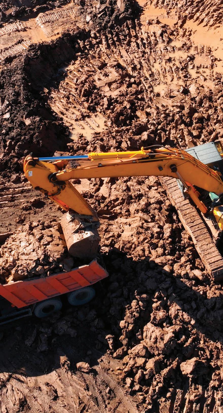

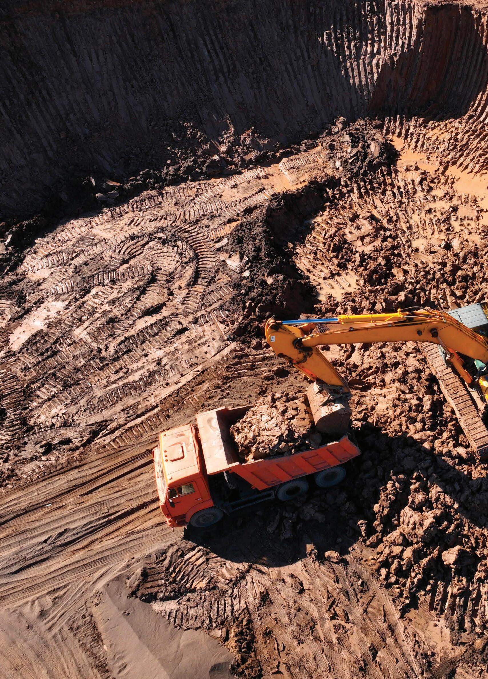
offering innovative products, it is also important for suppliers to offer localised technical support and a robust supply chain to ensure consistent and reliable performance in diverse market conditions.
The capstone lever in cement optimisation is selection of appropriate quality targets. This goes beyond simply setting fineness targets and determining optimal sulfate addition, leveraging the value created through the whole optimisation chain to enhance cement quality, reduce energy consumption, and minimise CO2 emissions.
Cement performance can be tailored to market demands, increasing strengths to reduce concrete cement contents, accelerate project timelines, or adjust setting times and workability. This flexibility allows for optimised concrete

Figure 4. The impact of cement fineness (BSSA) and 1-day and 28-day compressive strengths. Data represents Type I and Type II cements, filtered for similar chemistry.
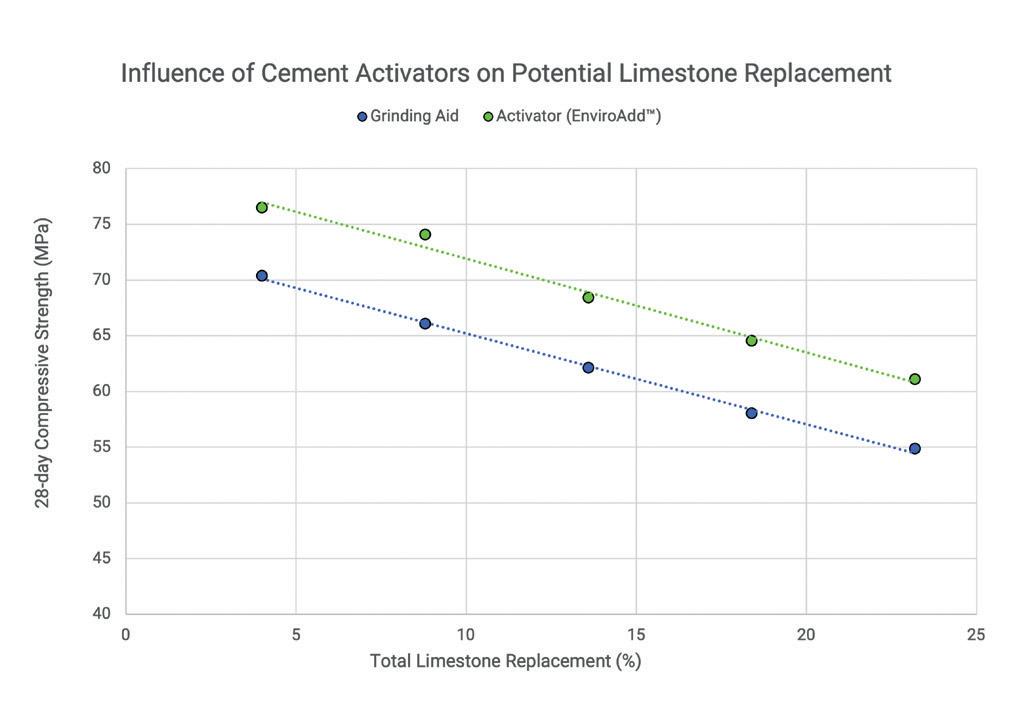
Figure 5. The impact of blending ground limestone (BSSA = 600 m2/g) into an industrial cement (BSSA = 450 m2/g) produced with a non-performance enhancing grinding aid (blue) and into the same cement with an admixed activator (orange).
mixes with lower CO2 footprints and faster completion times.
Coarser grinding
Cement fineness affects strength, setting characteristics, and water demand. Coarser cements reduce temperature rise, capillary stresses, plastic shrinkage tendency, and micro-cracking in concrete.3 Consequently, more reactive clinkers achieving the same strength at lower fineness are of particular interest to the industry. For a typical cement, a 1 MPA strength change corresponds to a change in BSSA of approximately 20 – 25 m²/kg (Figure 4), which further translates to an approximate change of 7% in energy consumption.4 As such, full system optimisation enables reduced fineness, increasing mill productivity and lowering CO2 emissions.
Portland-limestone and blended cements are one of the key CO2 emission reduction levers identified in the Global Cement and Concrete Association’s 2050 Net Zero Roadmap.5 Each 1% clinker substitution reduces CO2 output by nearly the same amount, but impacts strengths at higher levels (Figure 5), necessitating finer grinding and leading to potential plastic performance changes in the field. As such, full system optimisation is necessary to maintain performance with decreasing clinker contents. Further CO2 reductions can be achieved with SCMs like slag, fly-ash, and pozzolans, which can enhance strength and durability.
Clinker reformulation and kiln optimisation
Optimising clinker formulation and kiln operation can help balance plant capacities with some reduction in CO2 emissions. Adjusting the kiln feed lime saturation factor can improve fuel efficiency and kiln output, though it may reduce strengths. Optimisation of the milling process and additive selection can help offset the strength losses, facilitating the use of alternative fuels and raw materials when warranted, enabling higher recycling rates.
A full systems approach to cement optimisation can also help free up mill capacity, reduce mill run-hours, facilitate preventative maintenance, and enable clinker import and grinding to adapt to changing market demands. Benefits vary by plant and cement type, but can all contribute to a sustainable strategy.
A holistic approach to cement optimisation involves addressing all aspects of the process to ensure that the full potential is realised at each stage. This not only improves production efficiency and cement quality, but also contributes directly to the overall sustainability of the cement manufacturing process. Cement producers who effectively address all four levers – proper clinker formation, mill optimisation, effective additive selection, and optimising quality targets – are succeeding in achieving their vision of blended cements to meet modern needs and are paving the way for a more sustainable future in construction.
1. CLARK, M., 'Clinker C3S Paramount', International Cement Review, March 2013
2. STANZEL, T., STOPPA, & CHEUNG, 'Using strength-enhancing cement additives' from 'Cement Plant Environmental Handbook 3rd Edition', 2022 International Cement Review.
3. BENTZ, D., GARBOCZI, E., HAEKCER, C., & JENSEN, O., 'Effects of cement particle size distribution on performance properties of portland cement-based materials.' Cement and Concrete Research, 29, 1663 – 1671.
4. ALSOP, P., 'The Cement Plant Operations Handbook, 7th Ed', 2019, Tradeship Publications Ltd.

5. 'The GCCA 2050 Cement and Concrete Industry Roadmap for Net Zero Concrete' – https:// gccassociation.org/concretefuture/wp-content/ uploads/2022/10/GCCA-Concrete-FutureRoadmap-Document-AW-2022.pdf
About the authors
Michael Stanzel is the Technical Sales Representative for Chryso Saint-Gobain, for cement additives in Canada. He holds a Bachelor's degree in Chemical Engineering from Queen’s University, Ontario, and has 24 years of experience in cement plant operations and quality control, and in concrete applications. Michael is an active member on the Canadian Standards Association (CSA) A3000, Cementitious Materials Compendium, and CSA A23.1/.2, Concrete Materials and Methods of Concrete Construction.
Oliver Sohn is the Field Technical Services Manager for Chryso Saint-Gobain, Cement North America. A graduate of the US Naval Nuclear Power Programme, Oliver also holds a bachelor’s degree in business. Oliver has held several key positions in the cement industry, including Quality Manager, Production Manager and Business Analyst. Oliver was a licensed roofing and residential contractor, prior to joining the industry.
Process improvement is like climbing. With a strong partner, you can overcome any obstacle.
Just as athletes rely on their teammates, we know that partnering with our customers brings the same level of support and dependability in the area of manufacturing productivity. Together, we can overcome challenges and achieve a shared goal, optimizing processes with regards to economic efficiency, safety, and environmental protection. Let’s improve together. Do you want to learn more? www.endress.com


Gopala Rao Dhoopadahalli and Sheo Pujan Pandey, UNISOL CHEMTECH
LIMITED, examine the role of grinding aids in enhancing the productivity, efficiency, and sustainability of cement production.
The use of grinding aids (GAs) to improve mill productivity is a well-established practice in the cement industry. The growing demand for concrete consumption, driven by increasing construction activities in developing countries of Asia, Africa, and Latin America, has led to higher cement production globally. The production of clinker is an energy-intensive process with significant carbon emissions. A key approach to control these impacts is reducing clinker production. Moreover, it is always encouraged to reduce the usage of clinker for cement production by utilising industrial byproducts.
It estimated in a roadmap that by 2050, the average clinker factor will be reduced to 0.60 globally.1 GAs play a crucial role in achieving this by enhancing grinding efficiency and optimising energy usage required for the production of cement. GAs and performance enhancers are usually added during the cement grinding process to improve the quality of the finished cement.
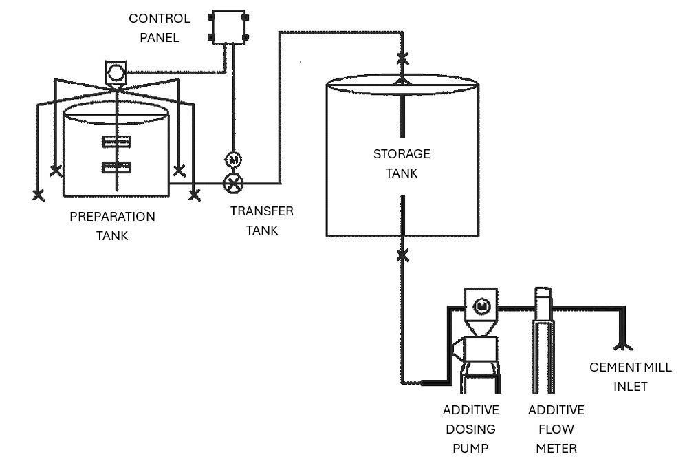
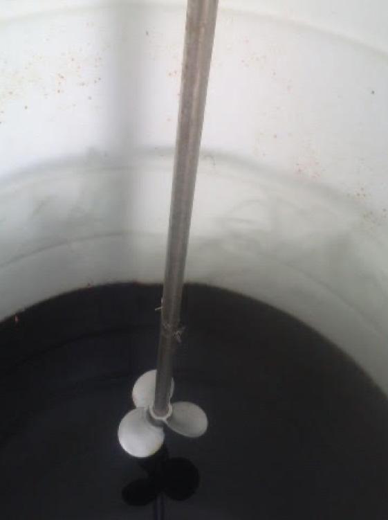
The primary objective of using ball mills to grind clinker and gypsum was size reduction. Thus, it is also used for grinding coal. In addition, the output product gets homogeneously mixed during grinding operation. Earlier, only ball mills were primarily used for grinding cement. However, the grinding media and walls of ball mills often became coated with fine ground cement, reducing productivity and grindability. The addition of GAs avoids these coatings and improves both grindability and productivity.
Developments in milling technology largely replaced the conventional ball mills with i) vertical roller mills or ii) a combination of a ball mill and a roller press. However, the choice of grinding method depends on factors such as feed size, desired output, hardness of input materials, operating conditions, and economic circumstances. The productivity enhancement was more in vertical roller mills (VRMs) as compared to ball mills. Thus, VRMs are currently favoured over ball mills for their efficiency and robustness.
Despite differences in the energy consumption of ball mills and vertical roller mills, the use of GAs remains critical across all grinding methods. GAs provide several benefits, as listed below:
f Ease the grinding process.
f Reduce the energy consumption.
f Enhance the production capacity in bulk units.
f Ensures desired quality consistently in the finished product.
In recent years, the role of GAs has expanded beyond improving productivity and achieving energy efficiency. Out of which, reducing clinker production is the utmost priority, with an ultimate aim of achieving carbon neutrality or even becoming carbon negative. Governments and other regulatory bodies may soon compel cement producers to use the GAs for cement production to meet these sustainability targets.
Usually, the GAs that are supplied to cement companies contain more than 60% water, resulting in huge transportation costs. However, UNISOL has a unique solution to tackle this problem by supplying only the active ingredients making the GAs to cement industries. The chemical additives used in the formulations are mixed at the site or at a nearby location for ease.
The on-site or near site blending approach offers a significantly enhanced operational model that benefits both the supplier and the client in many ways, as follows:

f Delivery of GA chemical additives to cement plants in a concentrated form, characterised by minimal to no water content.
f Addition of water at the cement plant location which is easily available locally.
f On-site mixing of chemical components and water in dedicated blending tanks (Figure 1).
f Dosing of the blended formulation into cement or raw mills.
The propeller type agitators fitted with electric motors are used for mixing various chemical additives in presence of water to obtain a homogeneous formulation (Figure 2).
The formulation is mixed in the mixing tank (Figure 3) and is then dosed at the inlet of the cement mills by a high precision dosing pump, which accurately doses the formulation to as low as 0.03% by weight of cement.
The on-site blending model provides several key advantages:
f Mainly reduces logistics costs, including freight, packaging, and handling expenses.
f Reduces carbon footprint due to more efficient transportation and production processes.
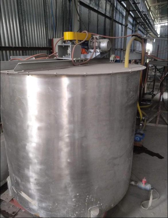
f Increased transparency in chemical formulation management at the client site.
f Enhanced flexibility in adapting products and formulations to meet varying operational requirements and objectives according to the requirements of the plant.
The production of portland cement clinker consumes more energy and resources. Thus, it is always attempted to reduce the use of portland cement clinker by replacing it with SCMs. However, the use of SCMs to replace clinker to produce blended cement changes several properties of the cement. Although the durability aspects of the blended cement are better compared to the ordinary portland cement (OPC), the early strengths achieved are very low. This is the aspect where GAs prove to be advantageous, helping in the widespread use of blended cements produced using any SCM.
The use of GA chemical additive compensates the drop in compressive strength obtained by the reduction of the clinker factor. These chemical additives added during grinding of cement enhance the cement strength in two ways:
f Through physical action.
f By chemical activation of clinker.
The addition of the GA increases the fineness, reduces the sieve residues, and at the same time redistributes the particle size distribution of the cement. Furthermore, the chemical additives added take part in the chemical reaction by accelerating the clinker hydration.2 Consequently, the GAs are designed in such a way that it is formulated by adding several chemical additives which can enhance several properties in the cement. Furthermore, it is widely accepted that the use of fly ash and/or slag is very common to produce blended cement. However, the proportions in which they are used depend on the quantity and the quality of their availability in the vicinity of the cement plant. Moreover, the quality of a particular SCM varies a lot from place to place. Thus, it is always recommended that the GA formulation is designed for a particular set of raw materials.
In India, the maximum allowable fly ash content in portland pozzolana cement (PPC) is capped at 35% by mass, according to Indian Standard IS 1489 (Part 1):2015. Cement manufacturers typically aim to utilise the full 35% of fly ash to reduce production costs. However, this results in a reduction in early strength, particularly at 1 and 3 days, which hinders the complete replacement

of portland cement clinker with fly ash as the availability of quality fly ash is a concern. Thus, the cement industry wants to utilise the wet fly ash or pond ash to replace high-cost dry fly ash. This case study illustrates the use of UNISOL GA chemical additives to achieve the maximum possible utilisation of wet fly ash while maintaining the required strength of PPC.
UNISOL Chemtech Ltd. was approached by a cement plant to provide a solution for compensating the loss in 1-day strength due to clinker factor reduction. The main objective
Table 1. Utilisation of pond ash replacing high-cost quality fly ash.
of this study was to reduce clinker factor by 3%, retaining the strength parameters at 1, 3, 7, and 28 days in PPC.
UNISOL Chemtech Ltd. conducted extensive lab trials with many formulations on PPC to achieve the above-said objective (Table 1). Although there is a potential to increase the fly ash content up to 35%, it was suggested by the plant to decrease the clinker factor by only 3%, as 4% of salt pan gypsum and 5% of crushed limestone is used.
It is well known that fly ash reacts at a slower rate with cement, and hence increasing fly ash by 3% might drastically reduce the 1-day strength. In these trials, it was attempted to obtain a similar strength as observed in existing PPC (31% fly ash) or more by using UNISOL GAs. The reduction in 1-day strength due to fly ash addition is tried to compensate by chemically activating the clinker. The laboratory ball mill (LBM) trials were started by grinding 4 kg of Blank PPC with 31% fly ash (21% DFA + 10% WFA) to establish a baseline for comparison. Thereafter, the wet fly ash was increased by 3%, reducing clinker factor to 0.57 from 0.60. The target Blaine’s of 330 m2/kg was achieved at 6000 RPM and was kept constant in the entire study. This case study shows that the formulation LASE-005 at the dosage 0.05% has been found compatible with the present cement composition and gives the following advantages among all the formulations tried:
f The quality parameters such as strength and setting times are retained at 3% clinker factor reduction.
f Moreover, the compressive strength at 1, 3, 7, and 28 days is enhanced by 0.50, 1.57, 2.68, and 4.6 MPa, respectively, from the baseline/Blank, even after 3% more wet fly ash.
f The formulation has increased the Blaine’s from 333 m2/kg to 342 m2/kg and reduced the residue at 45 μm from 26.80% to 23.63%, indicating a significant increase in cement mill’s productivity.
Nowadays, the use of alternative raw materials and fuels (AFRs) are gaining more popularity in the cement industry


MAY 4th -8th, 2025
to achieve circular economy. For example, use of phospogypsum in place of mineral gypsum is most common.
The use of flue gas desulfurised gypsum (FGD gypsum) or salt pan gypsum is also gaining traction. It is well known that mineral gypsum is a naturally available depleting resource, and the quality of the material also varies with geography. Since it is not locally available, it needs to be imported or transported to greater distances. In order to reduce the production cost of cement, currently the above-mentioned byproduct gypsums are used to replace mineral gypsum, which eventually proves to be economical. However, it is reported that by using byproduct gypsum, longer setting times are seen in addition to the low early strengths at 1 and 3 days, irrespective of the cement type.3
A case study shown below illustrates the use of UNISOL GAs to incorporate various types of gypsums in PPC. In this case study, high-purity gypsum was replaced with a combination of different types of gypsum, and the strength achieved at 1 and 3 days at the plant was below the target strength. However, by using UNISOL GAs the target early strengths were achieved despite the use of these by-product gypsums. The PPC produced contained 5.6% of low purity gypsum (around 50% purity), along with a combination of several chemical gypsums viz., 0.5% of phosphogypsum, 1.7% of FGD gypsum, and 0.2% mould gypsum. The basic tests on cement produced were conducted and the results are shown in Table 2.
This case study shows that all the formulations used, enhanced the compressive strengths at both 1 and 3 days. However, ADSE-008 at 0.06% is found most compatible and proves to be beneficial among the other formulations for the following reasons:
f The setting times are not altered, though there exists a slight increase in the Blaine’s and a reduction in normal consistency of the cement.
f Mainly, the compressive strength of the PPC was seen enhanced by around 2.0 MPa and 3.50 MPa, respectively at 1 and 3 days, from the control sample.
f In addition, the residues at 45 μm and 90 μm reduced by 0.56% and 0.16% as compared to the control sample, indicating a significant increase in cement mill’s productivity.
The expanding role of grinding aids GAs offer more flexibility in achieving various desired properties beyond just productivity enhancements. With the incorporation of GA chemical additives, it is possible to achieve multiple benefits, such as:
f Improved fuel efficiency while grinding coal.
f Productivity enhancement to boost mill output.
f Reduction of normal consistency of cement.
f Slump retention and setting time modifiers.
f Strength enhancers for early, later, and overall strength.
f Achieve water repellency in cement.
The reduction in strength and the early-age strength loss are compensated by incorporating a specially formulated GA that includes a setting accelerator and a strength enhancer. This approach allows for the optimisation of the active ingredients in any GA formulation, enabling the simultaneous enhancement of multiple properties by adding specific chemical additives to improve each property. Thus, GAs can act as a one stop solution for many problems that need to be addressed in cement.
The application of GA alone addresses most of the major problems in the cement industry, like excessive mining, life cycle of mines, carbon emissions, resource utilisation, etc. Most importantly, the cost of cement production can be lowered, even when considering the investment in GAs. The costs incurred from using GAs are justified by the reduction in the clinker factor. Therefore, it can be said that the science behind GAs is not new, but has been re-engineered to meet the current needs of the industry.
The formulation, designed for a specific combination of clinker, gypsum, and SCMs, may not necessarily be optimal for another type of cement. Even a slight change in the quality or proportion of any raw material requires further research to develop a new GA formulation. However, in most cases, the formulation used in the previous scenario, with minor modifications to the chemistry or dosages, proves to be more effective. It is often easier to adapt existing formulations to address changes in raw materials during cement production. Nonetheless, to truly optimise the formulation, proper research and development (R&D) is essential. Numerous trials must be conducted at the lab scale before scaling up to plant trials.
New robust formulations with high impact are designed to obtain premium quality cement in certain segments where performance is prioritised over the cost of the chemical additive. The incorporation of low-cost SCMs, alternative fuels, and raw materials is also gaining more popularity in the cement industry. As research advances, new formulations of GAs are being developed, optimising the performance of existing systems and catering to the evolving needs of the cement industry. The design and development of bespoke
Production targets. You need to hit them. We can help you do that with high-capacity crushing equipment that can be moved anywhere on your job site. Best of all, they’re compact yet powerful to get the results you need. And our crushing equipment won’t generate high levels of fine material and waste, setting you up for efficient cement production.
It’s the dependable equipment you need to hit your targets and confidently say your operations are … crushing it. komatsu.com/crushing
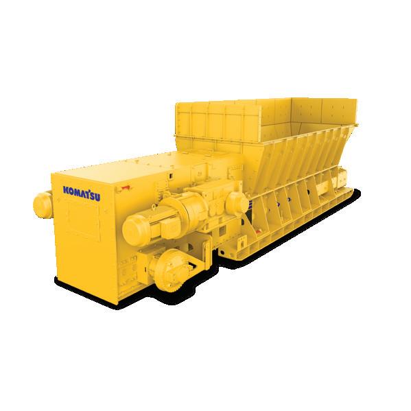
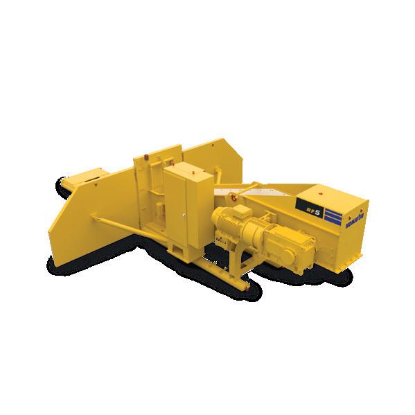

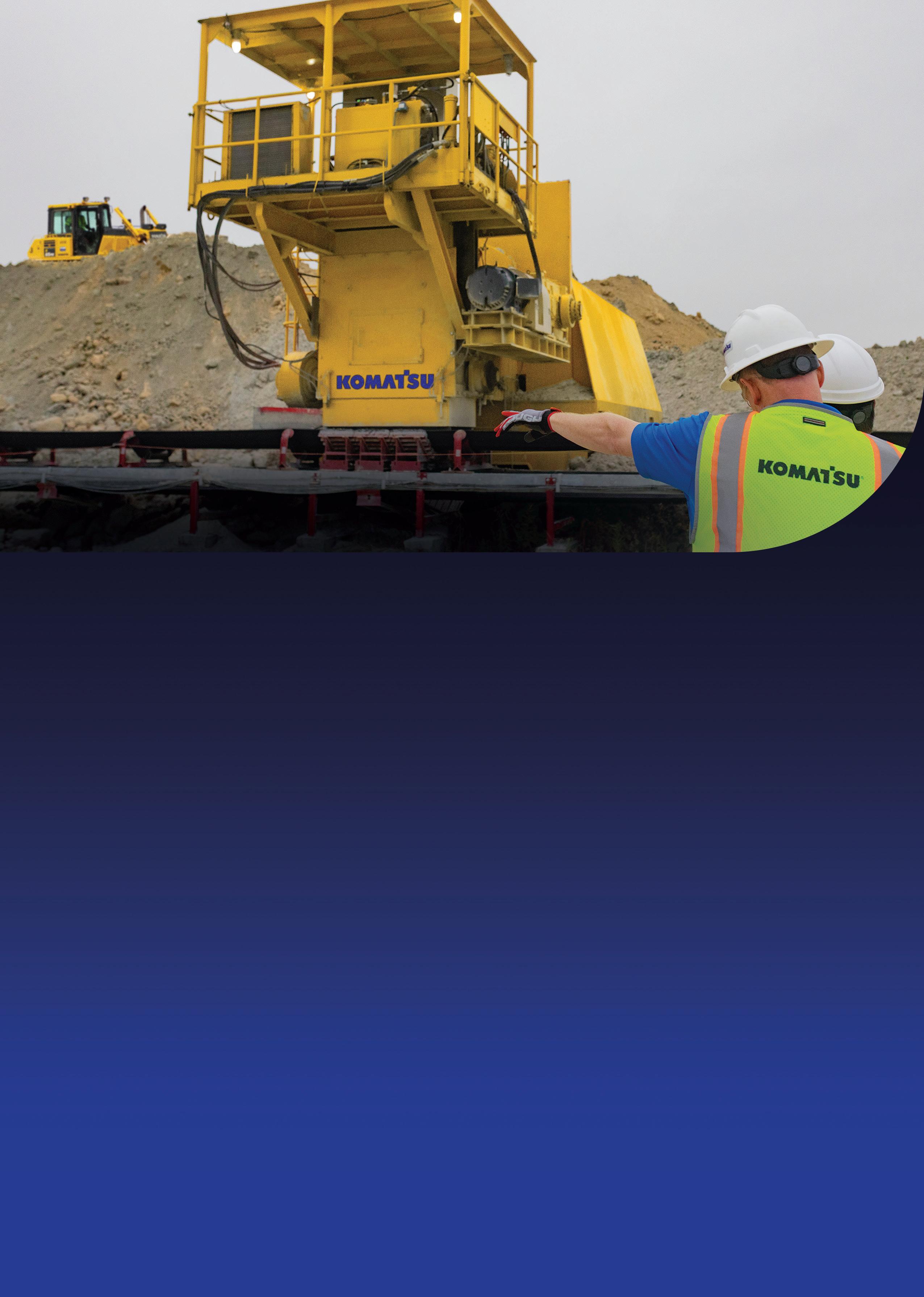
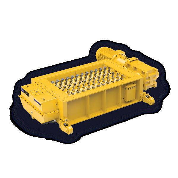
formulations for a particular case is the order of the day.
Carbon emissions remain a significant concern in the production of cement. The carbon dioxide generated during the production can be categorised into three main stages:
f Decomposition of limestone.
f Burning of fossil fuels.
f Consumption of electricity and fuels during grinding and transportation.
While the first two stages are largely unavoidable, reducing the consumption of such a high energy intensive material (i.e., clinker) is necessary to reduce carbon emissions. It is proved in time that the use of only SCMs cannot prove to be the ultimate solution to tackle the carbon emissions problem. However, the use of SCMs along with GAs can help better to lower carbon emissions.
It is well understood that mitigating carbon emissions at every level of operation involved during cement manufacturing is the driving force in bringing down the overall carbon emission levels. Thus, the cement industry is constantly striving towards reducing carbon emissions and is becoming more and more carbon conscious.
Globally, the production of OPC has been reduced over the last decade, reflecting the cement industry’s commitment to sustainability. Currently, it is reported that majority of the cement produced in India is blended cement amounting to 75% of the total cement produced.4 According to recent data,5 out of 95.95% total utilisation of fly ash, a major portion (around 25.4%) of fly ash is utilised by cement industry in making fly ash blended cement.
GAs are playing a key role in facilitating this shift by improving the efficiency of the production process and enabling the use of more environmentally friendly materials. In the near future, it will become inevitable for the cement industry to mandatorily use GAs to manufacture any kind of cement by reducing clinker factor.
Economics
Currently, the selection of the GAs is often driven by cost considerations, rather than performance. While performance factors such as grindability and efficiency are important, the economic feasibility of a GA formulation typically takes precedence. Optimising GA formulations to meet the specific needs of cement manufacturers is becoming increasingly vital in the context of cost-effective production.
Conclusion
The use of GAs, as discussed earlier, goes beyond simply enhancing mill productivity.
With the help of certain chemicals, clinker can be ground with gypsum and/or other raw materials, offering multiple advantages in addition to the primary purpose of improving efficiency. GAs are formulated to deliver a range of benefits by combining various chemical additives. The key conclusions that can be drawn are as follows:
f The use of GAs is essential for improving the productivity and sustainability of cement production.
f These grinding aids not only enhance mill efficiency but also contribute to reducing carbon emissions by enabling clinker factor reduction and the use of supplementary materials.
f The low-cost SCMs, like pond ash, going to landfills are creating a menace, and that can be incorporated in blended cement without any change or slight change in the properties of the cement.
f The development of cost-effective, high-performance GAs is crucial for cement manufacturers looking to meet both economic and environmental goals, as they facilitate clinker factor reduction and allow for the use of performance improving additives like limestone or by-product gypsums, as well as other AFRs .
f Multiple combinations possible to enhance various other properties in a single dosage.
f Carbon emissions can be tackled economically at ease rather than replacing the existing equipment with new high-efficient equipment.
f As the industry continues to focus on reducing carbon footprints, GAs will remain a valuable tool in achieving more sustainable cement production practices.
1. WBCSD, IEA, 'Technology roadmap for cement, International Energy Agency' (2018) 66.
2. RAMACHANDRAN, V. S., 'Hydration of Cement - Role of Triethanolamine', CemConcrRes6 (1976) 623 – 632.
3. ÖLMEZ, H., & ERDEM, E., 'The effects of phosphogypsum on the setting and mechanical properties of Portland cement and trass cement', CemConcr Res19 (1989) 377 – 384 – https://doi.org/10.1016/00088846(89)90027-6.
4. R. GETTU., R., PATEL, A., RATHI, V., PRAKASAN, S., BASAVARAJ, A. S., PALANIAPPAN, S., & MAITY, S., 'Influence of supplementary cementitious materials on the sustainability parameters of cements and concretes in the Indian context, Materials and Structures', Materiauxet Constructions52 (2016) – https://doi.org/10.1617/s11527019-1321-5.
5. Central Electricity Authority, 'Report on fly ash generation at coal/lignite based thermal power stations and its utilization in the country for the year 2021 – 22', (2022) 1 – 97.

Lars Andersen, HASLE Refractories, explores the critical role of dip tubes in preheater cyclones and highlights how the latest generation of vortex finders is delivering extended lifetimes and improved process stability.
In modern dry-process cement production, the preheater tower is essential for maximising heat exchange and optimising fuel utilisation in the pyro process. Each cyclone stage plays a distinct role, with upper-stage cyclones typically designed for high separation efficiency to ensure minimal raw meal losses while lower-stage cyclones are focused on effective heat transfer. The overall preheater performance is a function of each single cyclone stage’s performance and design; if one or more stages do not operate as intended, the remaining cyclones must compensate, leading to higher energy consumption in terms of both heat input and power.
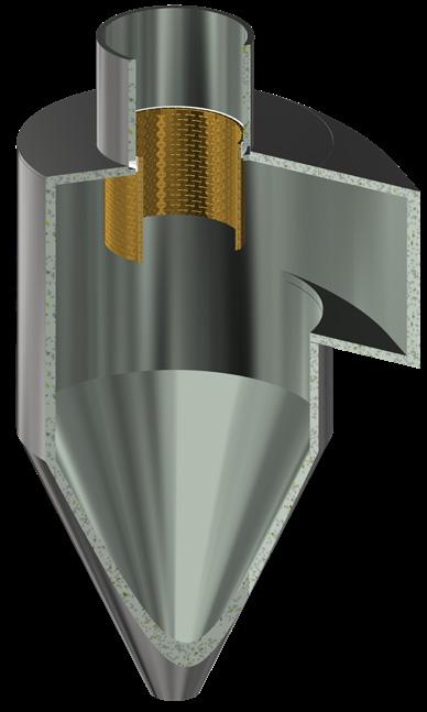
Figure 1. Vortex finders (also known as thimbles and dip tubes) are installed in preheater cyclones to improve the separation between the raw meal and the hot gas, thereby increasing the efficiency and process stability of the preheater process. But some plants choose to run without a dip tube in the lowest stage cyclones due to issues with short lifetimes.
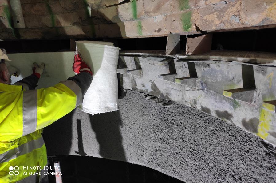
Figure 2. Installation procedure; Following the welding of the steel support ring to roof casing of the cyclone, ceramic fibre blankets are placed against the steel ring to ensure sufficient space for thermal expansion.
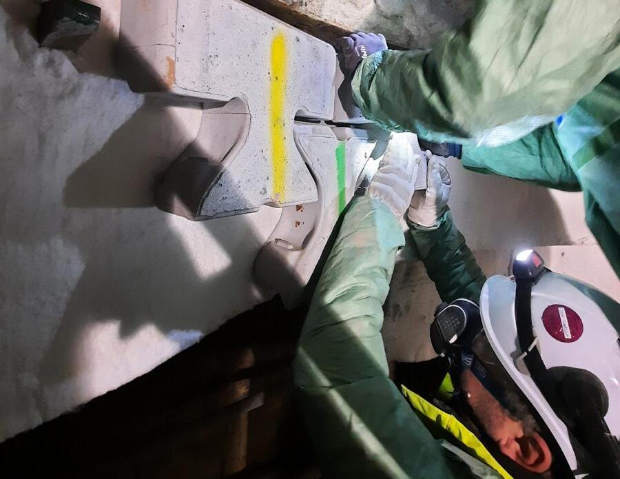
Figure 3. Assembling the HASLE CVF (Gen3): the top row of ceramic elements is placed on the brackets of the steel support ring; the remaining elements are suspended from the elements in the top row.
Within the cyclones, the dip tube, also known as a thimble or vortex finder, plays a crucial role in defining the flow field and preventing the entering particles from shortcutting the cyclone. The dip tube is an integral part of the cyclone separation design, ensuring maximum separation efficiency of raw meal particles. The goal is that they are appropriately preheated before entering the kiln, contributing to the overall thermal efficiency and operational stability of the preheater system.
A missing or damaged dip tube significantly reduces separation efficiency leading to diminished quality due to unstable operation. Consequently, the heat recovery efficiency of the entire preheater tower is reduced, as a considerable portion of the preheated raw material particles circulates to the upper cyclone stages, prolonging the time before they enter the kiln.
Dip tubes help maintain optimal operating temperatures and system pressure balance, ultimately lowering the overall energy demand on the ID-fan. The dip tube influences the overall system pressure drop in two opposing ways. While they increase local pressure loss within the cyclone – leading to higher ID-fan power demand – their presence also lowers the mean operating temperature in each stage, significantly reducing gas volume flow. This reduction in volume flow decreases the energy required to transport the hot gases through the preheater, ultimately outweighing the additional pressure drop.
Accurately quantifying the energy savings of operating with an optimally designed dip tube is complex due to the varying system conditions and designs. However, based on customer feedback and internal calculations, operating without a dip tube in the lowest-stage cyclone typically increases heat input by 2 – 3% and ID-fan power consumption by 5 – 7%, highlighting the importance of maintaining a properly functioning dip tube for energy efficiency.
Traditional preheater designs were developed when cement plants primarily relied on coal, petcoke, and other homogenous fossil fuels. However, the cement industry’s shift toward more sustainable production has led to a significant increase in alternative fuel (AF) utilisation. Global players such as Cemex, CRH, Heidelberg Materials, and Holcim, report thermal substitution rates (TSR) approaching 40%,1, 2, 3, 4 while the European cement industry reached 53% AF usage in 2021, with CEMBUREAU targeting 60% by 2030 and 95% by 2050.5 It is not uncommon to encounter certain individual plants today that can exceed 90% AF substitution.
AFs are primarily introduced in the calciner section of the preheater, where they bring new operational challenges. Unlike conventional fuels, AFs vary significantly in size, heat value, and combustion characteristics. This leads to temperature and

If you use high-pressure grinding rolls (HPGR) for their high efficiency, rely on Hägglunds to take it even higher. With shaft-mounted motors and a low moment of inertia, Hägglunds hydraulic direct drives limit torque peaks instead of opening the roll gap – so that you grind the first time and waste less energy reprocessing. Count on flexible power and cost-saving reliability, supplied by a team that’s driven to the core.
Hägglunds is a brand of Rexroth. www.hagglunds.com
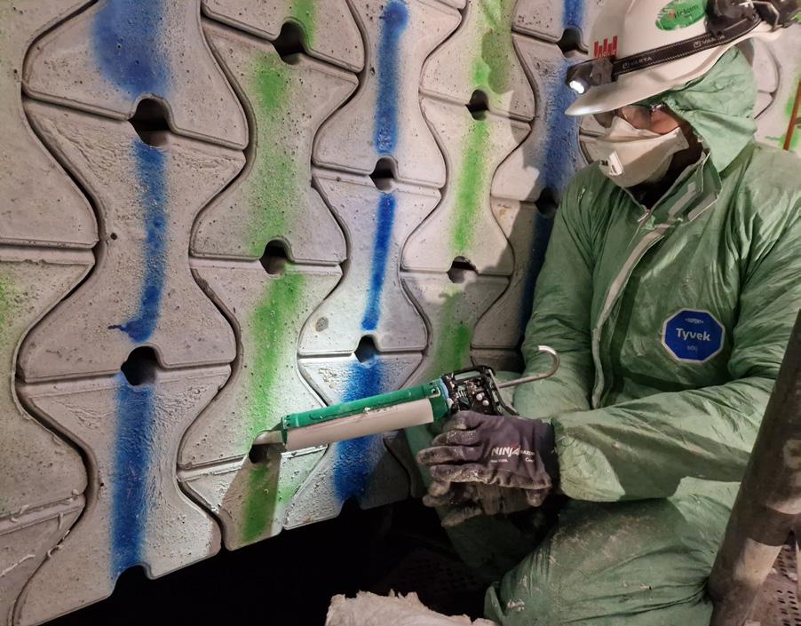
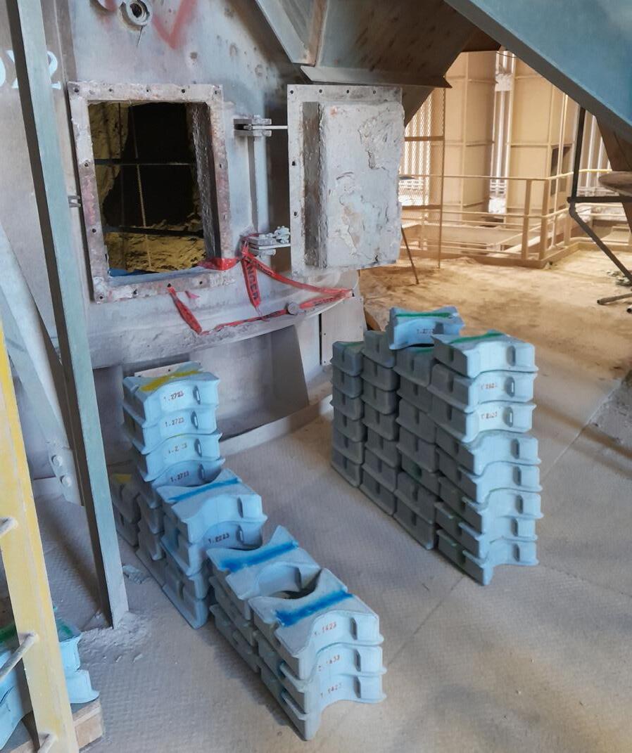
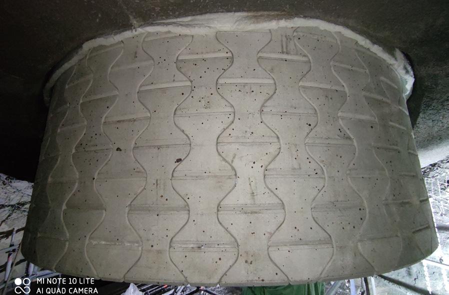
pressure fluctuations, incomplete combustion, and higher peak temperatures throughout the preheater cyclones. In lower-stage cyclones, peak temperatures may occasionally exceed 1150˚C, placing extreme stress on refractory linings and components such as dip tubes.
Traditional steel dip tubes, even those made from high-alloyed steel, face significant durability challenges in lower-stage preheater cyclones operating with high AF substitution rates. The increased thermal and mechanical loads accelerate creep and deformation, while burning AFs also increase the concentration of corrosive species in the gas phase – such as halides, acids, and alkali salts – intensifying the degradation of steel components. In extreme cases, steel dip tubes can fail within months, leading to production losses, emergency shutdowns, and operational inefficiencies.
Faced with these challenges, especially jeopardising plant uptime, many cement plants choose to operate without dip tubes in the lowest-stage cyclone to avoid frequent replacements. However, this comes at a cost – reduced separation efficiency, increased fuel consumption, and potential process instability. This trade-off underscores the need for more durable and suitable materials solutions that can withstand the harsh conditions induced by AF utilisation.
To address these issues, HASLE Refractories developed the Ceramic Vortex Finder (CVF) as a durable alternative to steel dip tubes. First introduced in the 1980s, the CVF is constructed from precast, pre-fired ceramic elements that interlock to form a stable, self-supporting cylinder, suspended from a steel ring welded to the cyclone roof casing.
Building on decades of field experience, following extensive laboratory and fields test, HASLE has introduced the Generation 3 CVF (Gen3 CVF) – a redesigned and upgraded version tailored to withstand the extreme conditions found in cement plants utilising high levels of AFs. The Gen3 CVF is manufactured from a newly developed high-performance castable, composed of pure synthetic raw materials to minimise impurities. Nanoparticles are incorporated to enhance fracture toughness and overall strength, while the material’s superior resistance to chemical attacks ensures long-term durability in highly corrosive environments.
Precision-engineered at HASLE’s Danish production facility, each ceramic element is cast in specialised moulds to achieve a smooth, impact-resistant surface and an optimised profile. The elements are then pre-fired at high temperatures, eliminating free and chemically bound water while maximising
mechanical strength. The result is a dip tube capable of withstanding temperatures up to 1200˚C and ensuring high dimensional stability without deformation or creep, which is critical for maintaining separation efficiency throughout its service life.
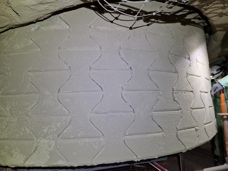
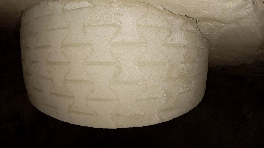
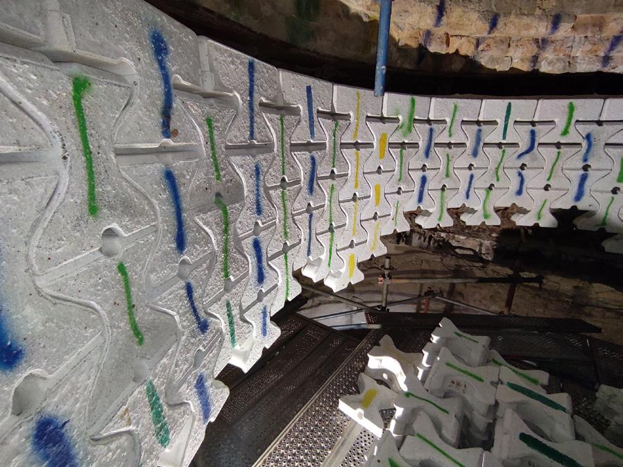
Additionally, the modular design of the Gen3 CVF offers several advantages. Its standardised shapes with different angles interlock through advanced tongue-and-groove joints, offering variable diameter options up to 7.5 m and lengths up to 5 m, providing adaptability to individual operating conditions and cyclone dimensions.
Weighing in at 15 – 16 kg per element allows use of existing manholes and easy handling during installation without the need for heavy lifting equipment. Furthermore, the small-sized ceramic elements minimise the risk of cyclone blockages in the rare event of element detachment, as they can pass through the feed pipe, allowing continued operation.
With the increasing challenges posed by high AF utilisation, cement plants worldwide require more durable solutions to maintain preheater efficiency and process stability. One such example is a 5000 tpd cement plant in Germany, which operates with up to 95% RDF (refuse-derived fuel) and other AFs in a dual-string preheater tower configuration.
The plant struggled with severe corrosion of steel dip tubes in both its lowest and second-lowest stage cyclones. In the lowest stage, where temperatures reach 950˚C, the steel dip tube had an extremely short service life of just 2 – 3 months, requiring frequent and costly replacements. To mitigate these issues, the plant temporarily operated without a dip tube in the lowest-stage cyclones. However, this approach proved unviable in the long run due to the aggressive environment inside the cyclones, combined with the specific cyclone design. Severe build-up and coating quickly formed inside the cyclones and feed pipes, significantly increasing the risk of blockages and unexpected stoppages for cleaning. The plant experienced multiple shutdowns throughout the campaign due to these operational instabilities.
In the second-lowest stage, where temperatures are around 850˚C, the steel dip tube lasted two to three years, but showed significant corrosion damage by the end of its service life.
Seeking a more robust and long-lasting alternative, the plant installed HASLE’s Gen3 CVF. The transition started with the second-lowest stage cyclones, where the HASLE CVF was installed in 2020 and 2021. The most recent installation has now completed four years of operation, successfully meeting its anticipated service life.
satisfactory lifetime with previous dip tube solutions.
Building on the successful implementation at the second-lowest stage, the plant introduced the HASLE CVF in the lowest-stage cyclones in early 2023. Since then, the CVF in these cyclones has achieved its one-year target lifespan, allowing the plant to complete a full campaign without emergency shutdowns caused by dip tube failure.
The Gen3 CVF has by time become an integrated part of the cyclone maintenance cycle for the plant due to its durability.
Following the initial field tests, the HASLE Gen3 CVF has now been implemented across multiple cement plants worldwide, demonstrating high durability and performance under diverse operating conditions.
In Australia, a 4000 tpd cement plant, running on 40% RDF, struggled with dip tube durability in its lowest-stage cyclone operating at 850 – 900˚C. The plant decided to run without any dip tubes in the lowest stage cyclone to minimise the risk of unscheduled shutdowns, as no dip tube solution could reliably operate for a full campaign at that point in time. Seeking a longer-lasting alternative, the plant installed the HASLE Gen3 CVF in January 2023. Beyond the projected fuel savings, the primary goal for the plant is that the CVF will contribute to an enhanced RDF combustion. This, in turn, aims to reduce the amount of unburnt fuel carried down
Meanwhile, the HASLE Gen3 CVF has also proven valuable in lower-AF environments. A 2700 tpd cement plant in the Southeastern part of USA, operating primarily on natural gas with 5% AF in the form of tires, faced short dip tube lifespans in its lowest-stage cyclone. At one point, the plant even opted to run without a dip tube due to persistent failures.
Seeking a more reliable solution, the plant installed a HASLE CVF in March 2024. The plant’s production superintendent noted: "We reached out to HASLE looking for new innovation to improve reliability and
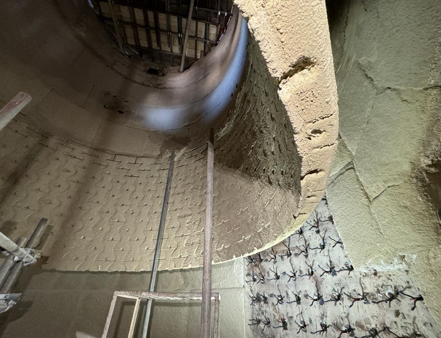
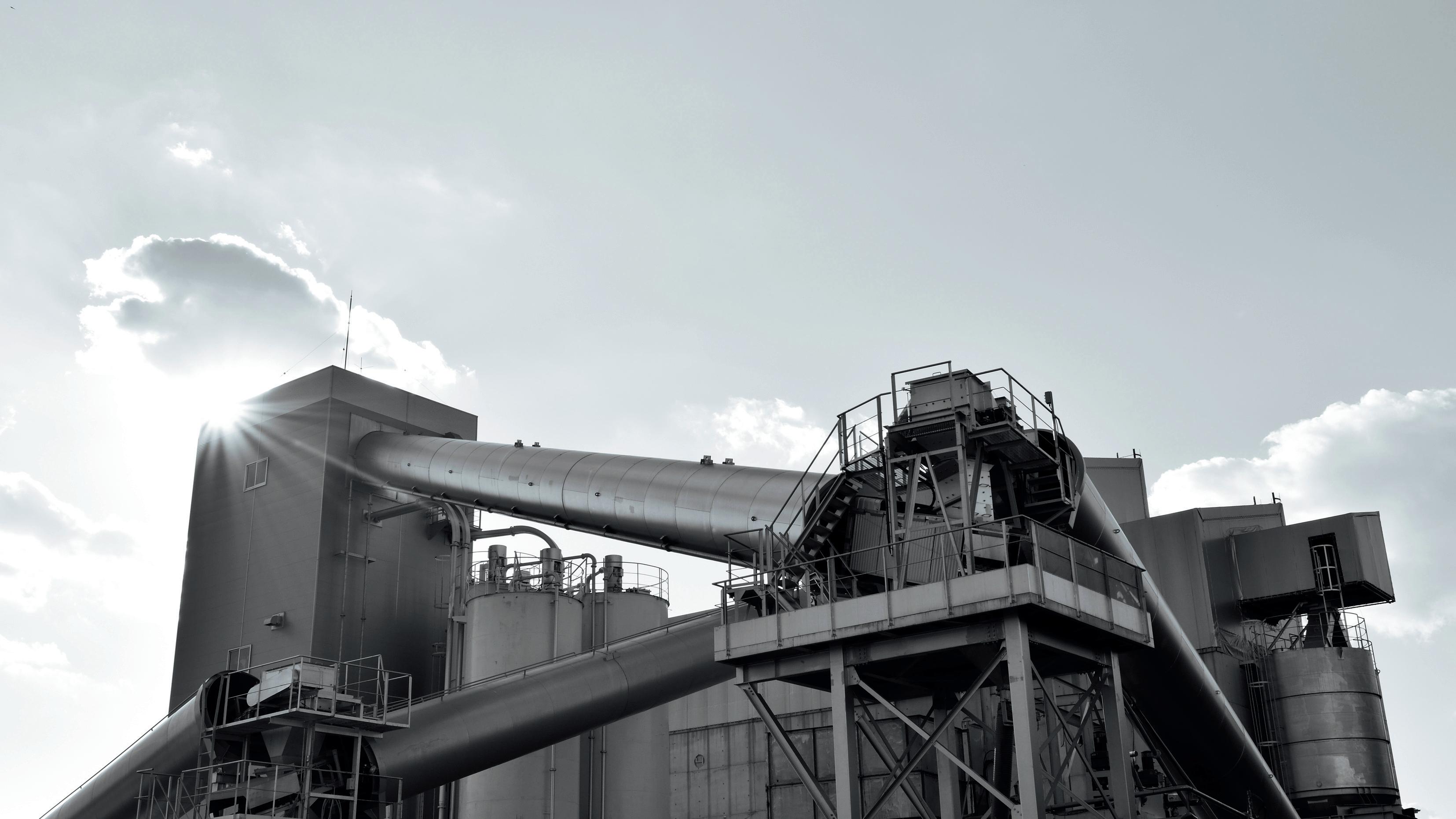


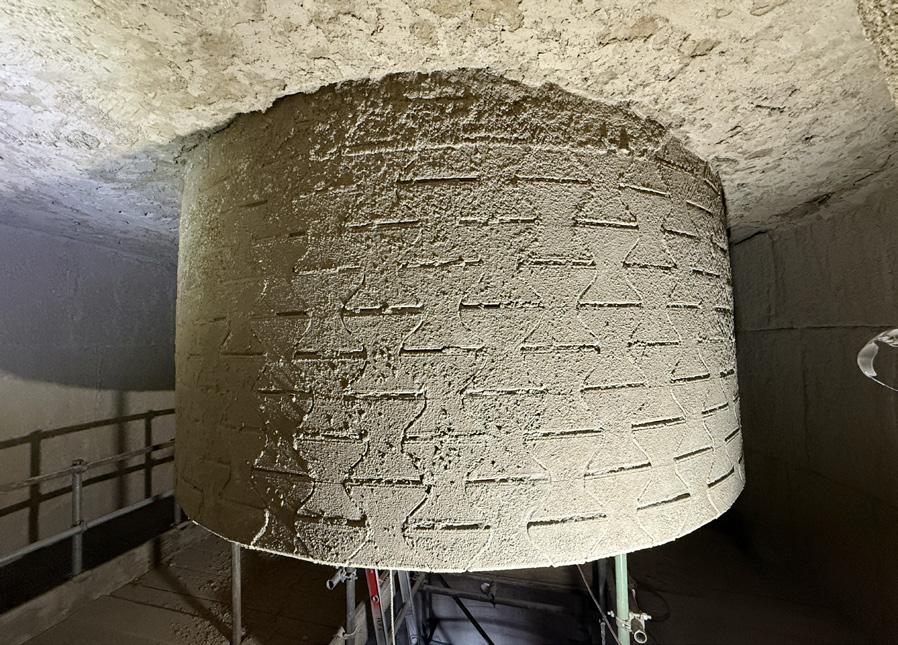
Figure 11. The CVF in the lowest-stage cyclone after 2 years of operation at the Australian cement plant. Following a comprehensive inspection, it was found to be in a good operation, leading to the decision to continue its operation for another campaign.
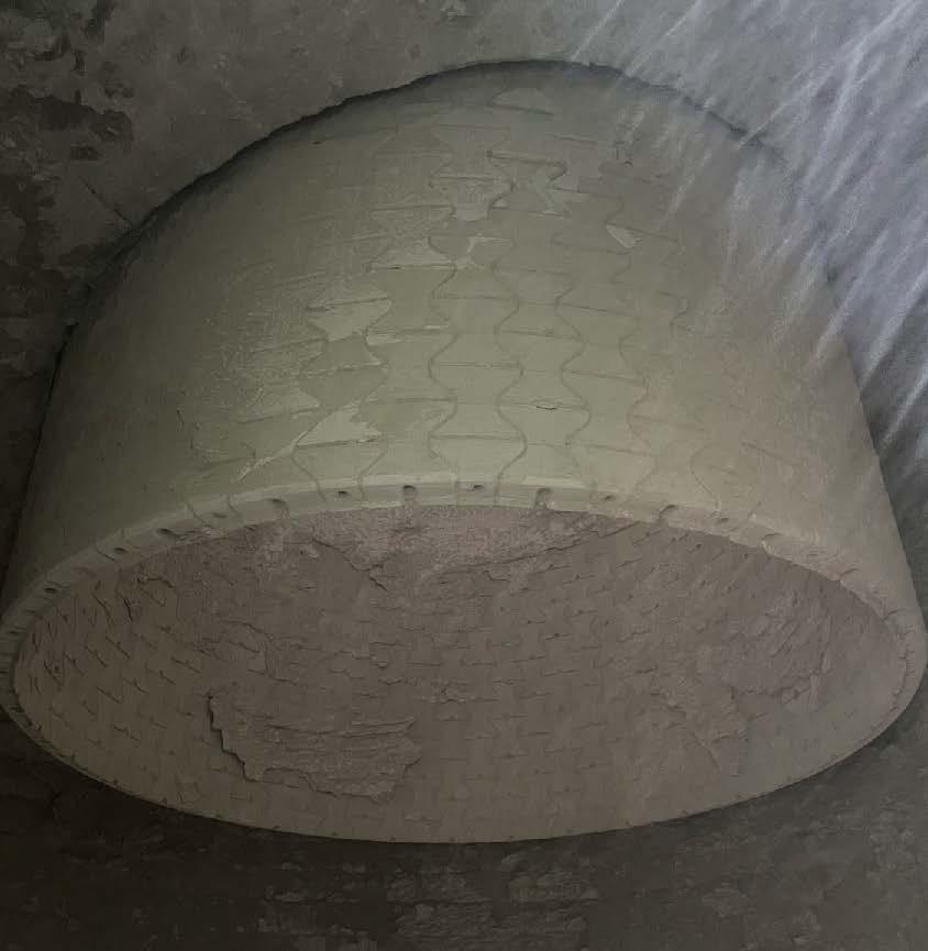
Figure 12. The CVF in the lowest-stage cyclone after 4 months of operation at a cement plant in Southeastern US, it continues to be in operation after 1 year.
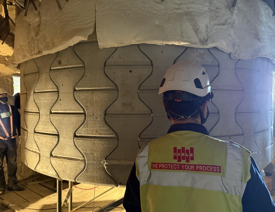
13. Latest, a CVF was also installed at a cement plant in Japan in November 2024. The first ever sales to Japan for HASLE Refractories.
longevity of our bottom-stage cyclone thimble (dip tube).”
During a scheduled shutdown in July 2024, an inspection confirmed that the CVF remained in excellent condition, and it continues to be in operation after 1 years lifetime.
More recently, a CVF was installed during November 2024 at a 3000 tpd cement plant in Japan, which is predominantly running on coal with 50% AF’s. The plant had previously run without a dip tube in its lowest-stage cyclone (820 – 950˚C) due to the short lifespan of previous steel dip tube solutions.
Although the design of the CVF was aimed for the lowest cyclone stages, it also has demonstrated its durability in middle stage applications. In Spain, a 3800 tpd cement plant, operating on 60% AFs, struggled with corrosion in the steel dip tube in the third-lowest-stage cyclone (650 – 700˚C). The steel dip tube typically lasted only 2 – 3 years before severe corrosion increased the risk of collapse, potentially blocking the cyclone cone and causing major process disruptions. Installed in 2020, The CVF is still running after more than 5 years of operation.
The HASLE Gen3 CVF enables cement plants to maintain high separation efficiency in the lowest-stage preheater cyclones, optimising thermal and energy consumption across the entire preheater tower, while increasing AF utilisation and thermal substitution.
With significantly extended lifetimes proven in both high- and low-AF environments, the HASLE Gen3 CVF continues to demonstrate its reliability, durability, and efficiency, offering cement plants a long-term solution for process stability and energy optimisation.
Engineered for extended service life, the CVF is designed to withstand the extreme conditions of high-temperature environments in cement plants with high AF feed rates, aiming to achieve a minimum lifespan of one full campaign.
1. Heidelberg Materials (2024): 'Annual and Sustainability Report 2023'
2. Holcim (2024): '2023 INTEGRATED ANNUAL REPORT'
3. CRH (2024): '2023 Annual Report'
4. Cemex (2024): '2023 Integrated report'
5. Cembureau (2024): 'From Ambition to Deploymentour 2050 roadmap'
Lars Andersen is the Product Line Manager for the CVF at HASLE Refractories, Denmark. Lars holds a master’s degree in mechanical engineering from the Technical University of Denmark and has over 25 years of experience in industrial equipment design and process optimisation for the cement industry.

M. Akritopoulos and T. Abbas, Cinar, explore the advantages of mineral interactive computational fluid dynamics (MI-CFD) in enhancing combustion efficiency, optimising alternative fuel use, and addressing challenges in the cement industry.
Before the advent of computers in the 1960s, simple and empirical calculations were the only tools engineers had at their disposal for designing combustors and kilns. In the 1970s, with the help of older generation computers of low computational power, 1D and 2D simple aerodynamics or gas-phase combustion calculations were possible. During this time, physical modelling techniques were developed, which proved very useful in visualising the mixing in the transient phase, and were widely applied for the estimation flow mixing pattern, i.e. lower velocity regions
and entrapment meal/fuel particles within a clear Perspex kiln model. However, physical modelling applications have gradually been phased out due to the availability of more computational power and the development of CFD models and its advanced version,
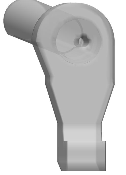
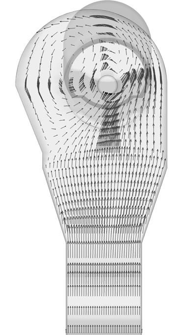
Figure 1. (Left) Kiln hood with asymmetry to the left (looking from burner). (Right) Kiln flow asymmetry in the hood increases flow stratification.
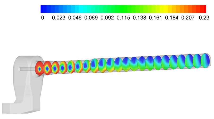
Figure 2. Oxygen concentrations: (a) from kiln hood to kiln exit, average exit oxygen concentration 2.8%; (b) at kiln back-end, exit oxygen concentrations varying radially between 0.1 – 4%.
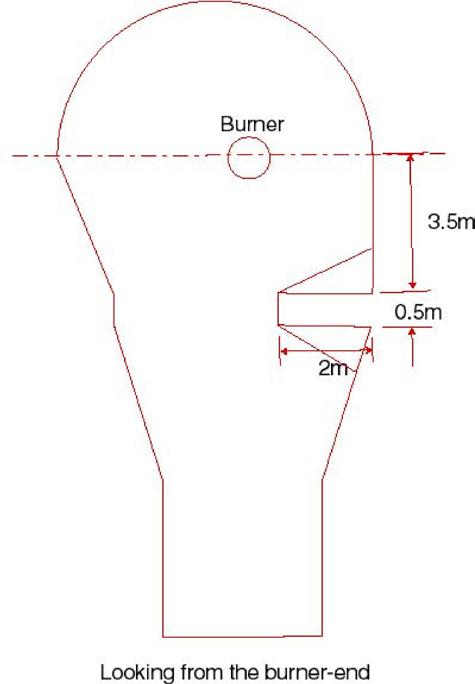
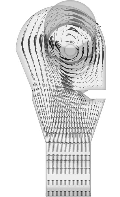
Figure 3. (Left) Schematic of an optimised insert to reduce the strength of the secondary air swirl. (Right) Vectors showing the result of the insert to initial secondary air.
the mineral interactive computational fluid dynamics (MI-CFD) techniques. The latter has been applied on and validated against over 400 kilns/calciners during the past thirty years and is now considered a mature technology that assists the cement industry in resolving process and combustion issues.
The MI-CFD technique, specifically developed for the cement and lime industries, is unique as it simultaneously calculates combustion and process interactions. For example, it accounts for CO2 release (and heat absorption) during the endothermic calcination reactions close to the kiln front-end. During these processes, species and heat exchanges between the gaseous and particulate phases must be obtained via concurrent interactive combustion and process calculations, a feature lacking in the general-purpose computational fluid dynamics (CFD) models.
In addition, MI-CFD model has an integral multifuel combustion characteristic, where several fuels burn concurrently depending on their reactivities in surrounding oxygen and temperature flow fields, with each fuel-specific reactivity, reaction rates, and physical properties. This feature captures the changes in combustion as a particular fuel burns and becomes lighter, or when a heavier chip drops down without fully burning. Once the combustion behaviour of a fuel fraction in a given geometry is recognised, cost-effective solutions can be easily implemented – such as simple burner tip modifications, relocations, or the addition of burners. These changes can be made based on 3D details that a plant can implement, as opposed to expensive upgrade solutions.
The usual MI-CFD-based solutions provide a payback time on the order of weeks or a few months. Examples include higher alternative fuel (AF) substitution, conversion from coal to natural gas, and reductions in CO, NOx, and UHC emissions, as well as dealing with hot spots, refractory failure, clinker quality issues, ball formation, and plugging causing higher pressure drop. The track record covers over 400 applications ranging from fabric filters, top cyclones, preheaters, to a vast array of calciners, kilns, and clinker cooler regions.
For example, in most plants, high-momentum kiln burners perform reasonably well. However, under AF co-firing or higher sulfur petcoke substitution, the layout of the clinker cooler, tertiary air take-off, and kiln hood configuration
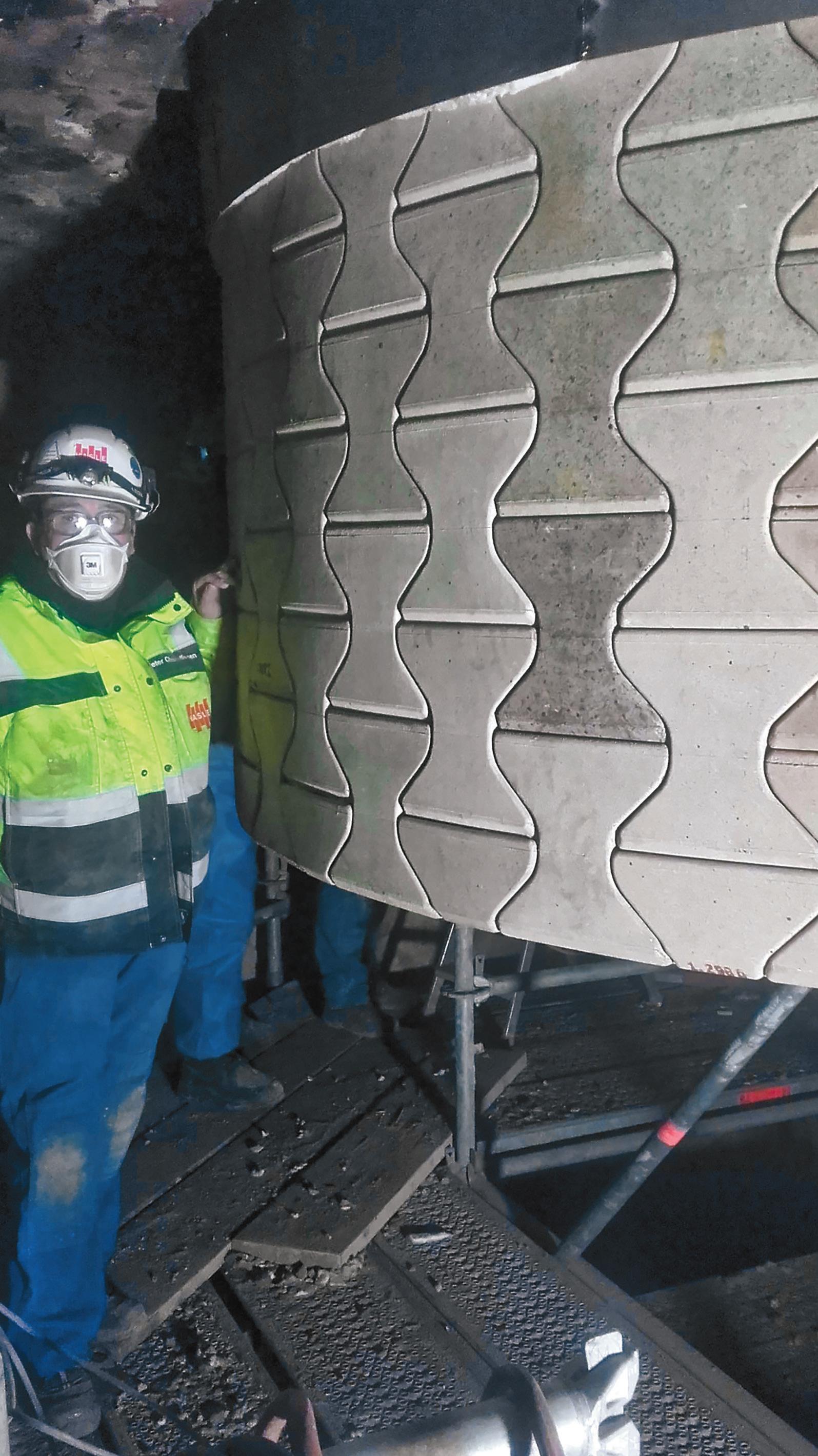
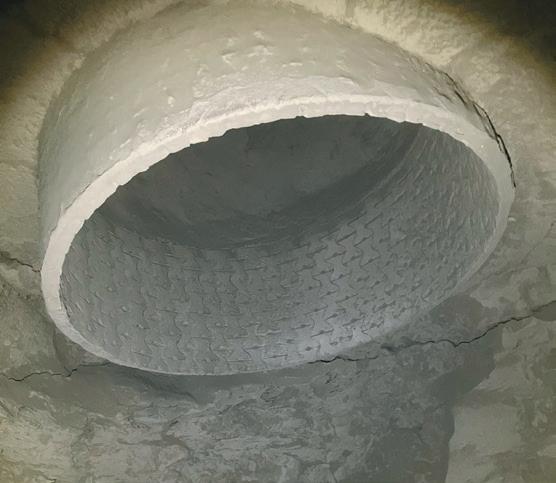
Germany - cement plant, lowest stage cyclone
Operating temperature: 950 °C.
Lifetime achieved: 1 year.
(Steel dip tube previously used achieved a 2-3 months lifetime).
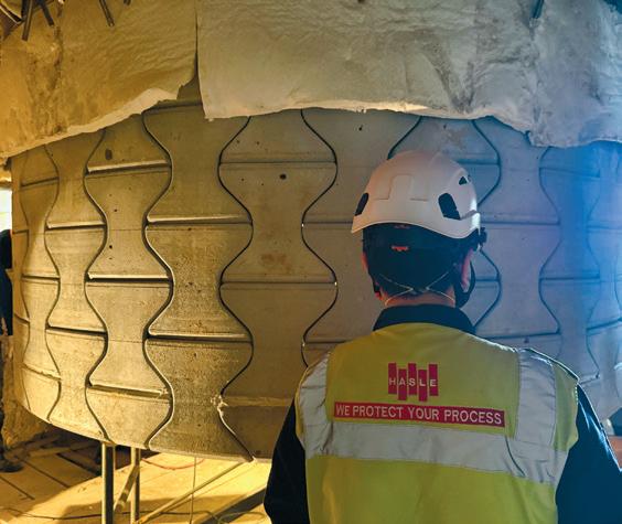
Japan - cement plant, lowest stage cyclone
Operating temperature: 950 °C.
Installed November 2024 and still running. 2 years lifetime expected. (Previously operating without dip tube).
The HASLE Ceramic Vortex Finder (CVF) is engineered to endure the harsh conditions of cyclones operating at elevated temperatures and utilizing alternative fuels, providing a durable alternative to traditional steel dip tubes.
The CVF is assembled on-site by individual ceramic elements, which interlock to form a stable tube hanging from a steel ring welded to the roof casing of the cyclone.
• Withstand temperatures up to 1200 °C / 2200 °F
• Enables sustainable fuel conversion through excellent resistance to chemical attacks
• High dimensional stability prevents deformation, ensuring high separation efficiency
• High abrasion resistance
• Smooth surface - Minimal build-up and coating
• 15–16 kg per element allows for easy handling during installation and use of existing manholes
• Variable diameter options: 1.5 to 7.5 metres
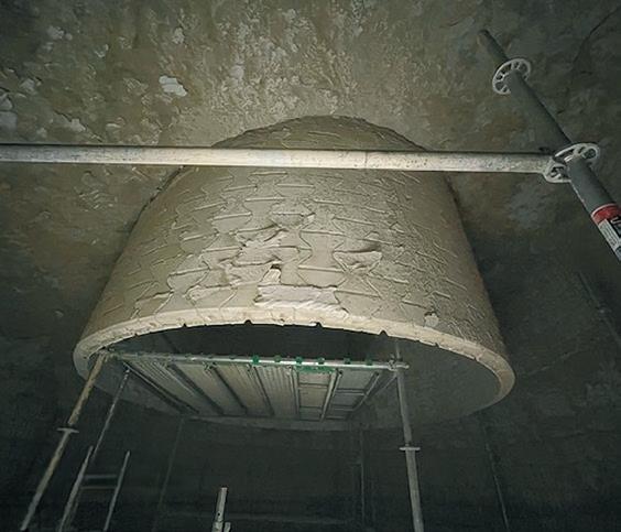
USA - cement plant, lowest stage cyclone
Operating temperature: 900 °C
Achieved 1 year of operation and still running.
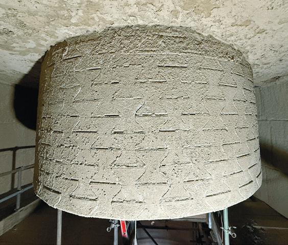
Australia - cement plant, lowest stage cyclone
Operating temperature: 850-900 °C.
Achieved 2 years of operation and still running. (Previously running without dip tube).
may produce an asymmetrical flame, thereby proving challenging to operate the kiln under optimum and stable conditions (Figure 1).
In Figure 1, flow asymmetry led to a lack of oxygen mixing, creating radially higher and lower oxygen concentrations, which required
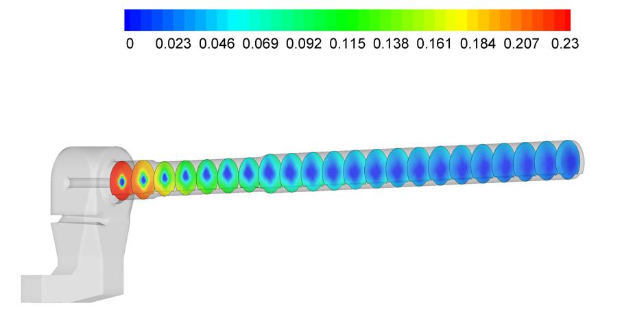
Figure 4. Oxygen concentrations: (a) from kiln hood to kiln exit, average exit oxygen concentration 2.8%; (b) at kiln backend, exit oxygen concentrations varying radially between 2 – 3%.
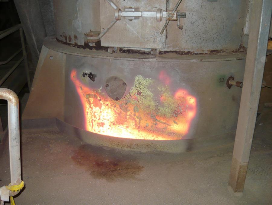
5.
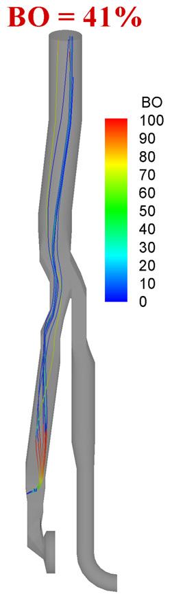
Figure 6. MI-CFD predicted lower burnout of a low volatile AF burning very close to the opposite wall.
higher excess air conditions to control CO emissions.
Upon analysing the kiln with the MI-CFD model, it was observed that the side off-take of the tertiary air location, with respect to the cooler layout and kiln hood, induces a biased swirl motion to the entrained secondary air. The 'flow-biasness' surpasses the external recirculation zones and continues and propagates until the kiln back-end, causing high CO formation within the fuel-rich segments of the fuel volatiles. The exit oxygen concentrations show regions of high oxygen (4%) and extremely low oxygen areas (0.1%).
High CO concentrations were measured at the kiln exit, varying between 5556 to 2230 ppm, with average values exceeding 3000 ppm.
Several possible solutions were tried to reduce CO emissions, including oxidation attempts later in the calciner. However, CO emissions remained high, approaching the permitted legislative levels. A cost-effective solution has been to break up swirl motion earlier by building a wedge-shaped refractory section (Figure 3). The slight geometrical change at the end of the narrow section of kiln-hood resulted in reduced strength of the swirl. The exit oxygen concentrations became more uniform at the kiln back-end with radial variations between 2 – 3%, and CO concentrations reduced to less than 400 ppm.
In another example, a plant observed ball formation that affected clinker quality. This issue could not be related to the kiln burner or the raw feed mix until a hot spot in the calciner caused a plant shutdown (Figure 5). MI-CFD analysis revealed that under reduced clinker production conditions, a low volatile AF was burning too close to the opposite wall. The strong burner momentum, combined with the lower kiln gas flowrate, was sending the AF material toward the opposite wall, eroding the refractory. Additionally, the extremely low burnout (< 40%) increased the hot-meal carbon content, driving sulfur cycles and initiating ball formation at the kiln front-end (Figure 6).
Tracking the burnout propagation of a fuel stream is another MI-CFD feature, which helps process engineers make necessary modifications to calciner burners. This is applicable to all fuels (Figure 7), allowing the visualisation of the burnout of each burner fuel and identification of specific burnout characteristics. The optimisation can then be attempted by modifying the burner inlet location, fuel injection angle, and velocities to minimise flow stratification and prevent oxidation reactions.
The measurements, when taken, such as carbon in hot-meal, only reveal the total
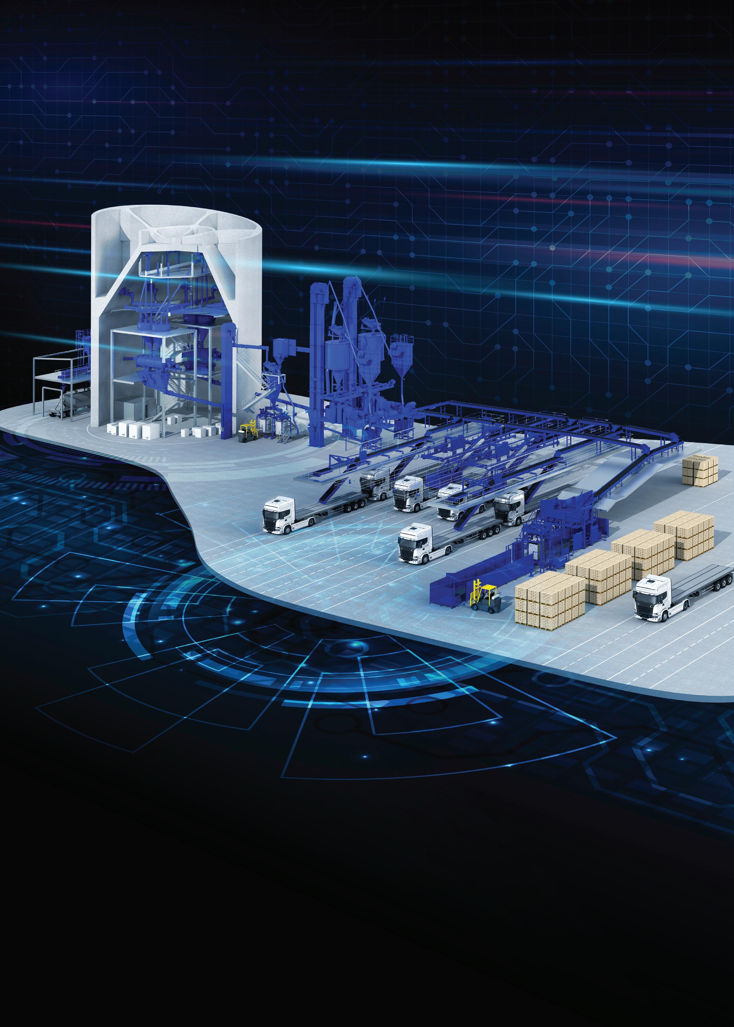
burnout, which is still helpful but leaves several expensive optimisation options without signalling out the underperforming burner.

7. Coal particle burnout from each burner can be traced and improved with low Capex modifications.
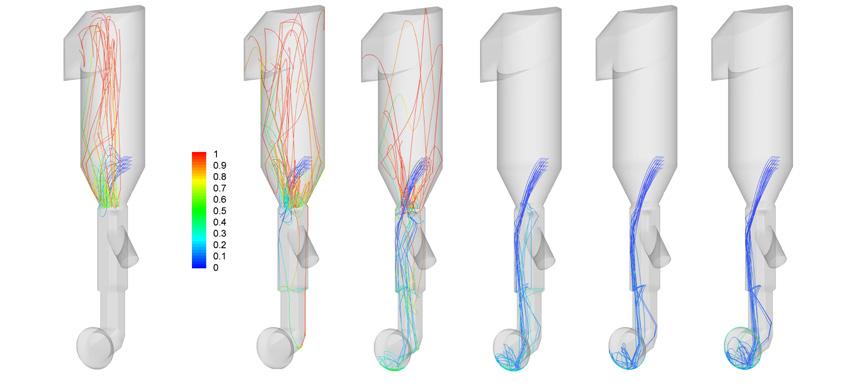
Figure 8. Larger particles' fate as smaller particles are captured by restriction at the top (Left to Right). (<35x35) (100%B/out), (35x35) (96%), (55x25) (64%), (55x45) (29%), (75x45) (20%), (>75x45) (17%).
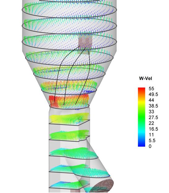
Figure 9. Tyre chip trajectories passing through lower velocity regions will adversely affect the suspension potential of chips.
When it comes to AFs, calciners offer much higher substitution rates than kilns. This is due to the flexibility of several ports at multiple locations and the provision of firing higher sized/density chips under optimal design conditions. The AF chip-size, moisture content, and injection location(s) concerning tertiary air and meal inlets are of paramount importance.
The riser and tertiary air duct velocities are also important when dealing with higher density/chip AFs. These velocities, for most calciners, range from 20 to 28 m/s, typically designed for conventional fuel firing conditions. The upward velocities to levitate the tyre/wood chips size of 50 x 50 mm (10 mm thickness) are 40 – 45 m/s over a distance of 2 – 3 m. These higher velocities are not usually available in most calciners, although in some cases, such velocities can be achieved for a shorter distance (half to a quarter of a metre). For example, in the calciner of Figure 8, most tyre chips, after partially burning, fall down on the kiln hearth except for the smallest fraction, which is suspended and entrained by the kiln riser's upward flow.
The tyre chips fall randomly and chaotically, facing both lower and higher velocity regions (Figure 9).The chip inlet may be re-located at a favourable injection angle, provided the accurate locations of velocity profiles are known.
When a larger proportion of semi-burnt chips fall into the kiln hearth area, not only do build-ups occur, but the carbon in hot-meal increases, which in turn drives the sulfur cycles, leading to higher pressure drop conditions. The predicted results can identify the over-sized AF chips which fail to burn and can be eliminated from the supply chain. An additional measure, such as locally increasing the upward velocities, can also be implemented. The installation of a Venturi-type refractory restriction helps to enhance the tyre chip burnout. The implementation of Venturi is justifiable as it reduces pressure drop caused by the irregular build-up of tyre chips. For example, with tyre-chips fallen in a long riser duct (Figures 10 & 11), it is seen that the bigger size chips initially descend, but then become suspended after entering the higher velocity section and also become lighter after experiencing devolatilisation. A 70% TSR of the calciner fuel was achieved with the installation of refractory Venturi restriction.
Conclusion
The principle of refractory throat restriction has proven to be very effective on several plants,
however, care must be taken to balance the flow rate of kiln riser and the tertiary air. In certain cases, in the absence of tertiary air-flow control, the secondary air entrainment to the kiln burner drops, which affects the kiln burner's performance by lowering the oxygen content in the riser duct gases.
The sulfur and chlorine contents of the AFR also need to be taken into account, which can be resolved by installing or optimising a bypass with the predicted results for the gas species, including both the major and minor species, as well as the gas temperatures. With the application of MI-CFD, plant engineers can analyse, refine, and select innovative optimisation solutions and upgrade ideas for the best performance and return on investment.
Figure 10. Solution with tyre chip injected from a higher, new location with Venturi restriction.
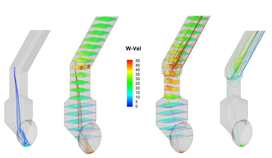
Figure 11. Comparison (in the lower region) of this solution to lower inlet location without Venturi restriction, showing vectors of upwards velocity component (W-vel) with tyre chips trajectories showing differences in suspension and burnout.
From turnkey solutions to annual inspections and repairs, we provide the industrial equipment maintenance and millwright services you need to meet your production demands.
SHUTDOWNS, OUTAGES & TURNOVERS
MAINTENANCE TEAM SUPPORT
EQUIPMENT INSTALLATIONS
ADJUSTMENTS / ALIGNMENTS
REPLACEMENT PARTS
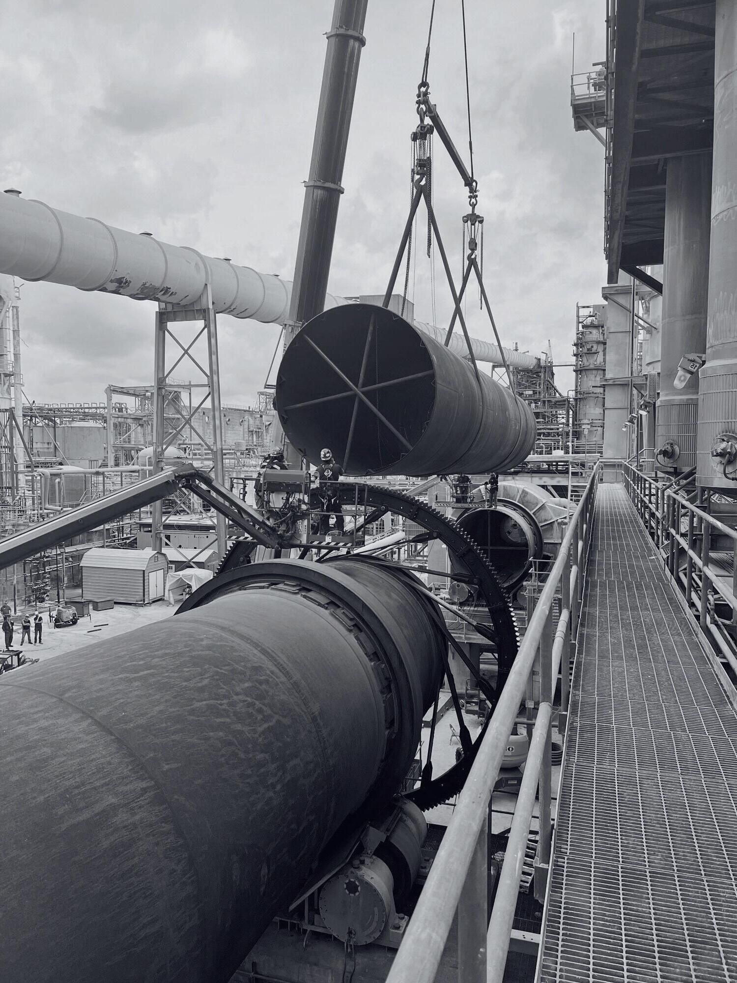
PREVENTIVE MAINTENANCE
FIELD AND SHOP FABRICATION & WELDING
MILLWRIGHT SERVICES
EMERGENCY CALLOUTS
We tailor solutions to meet your maintenance needs.


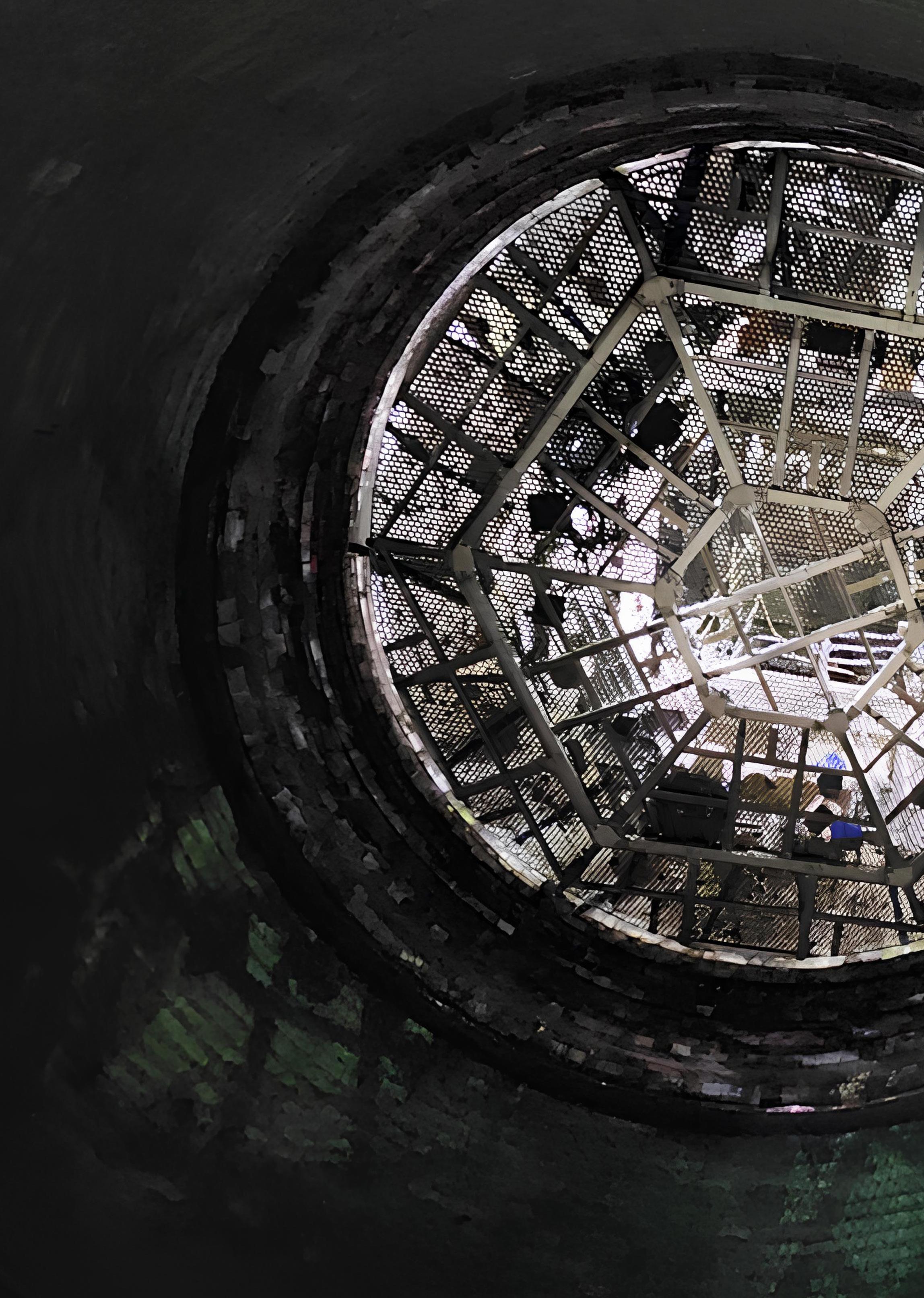
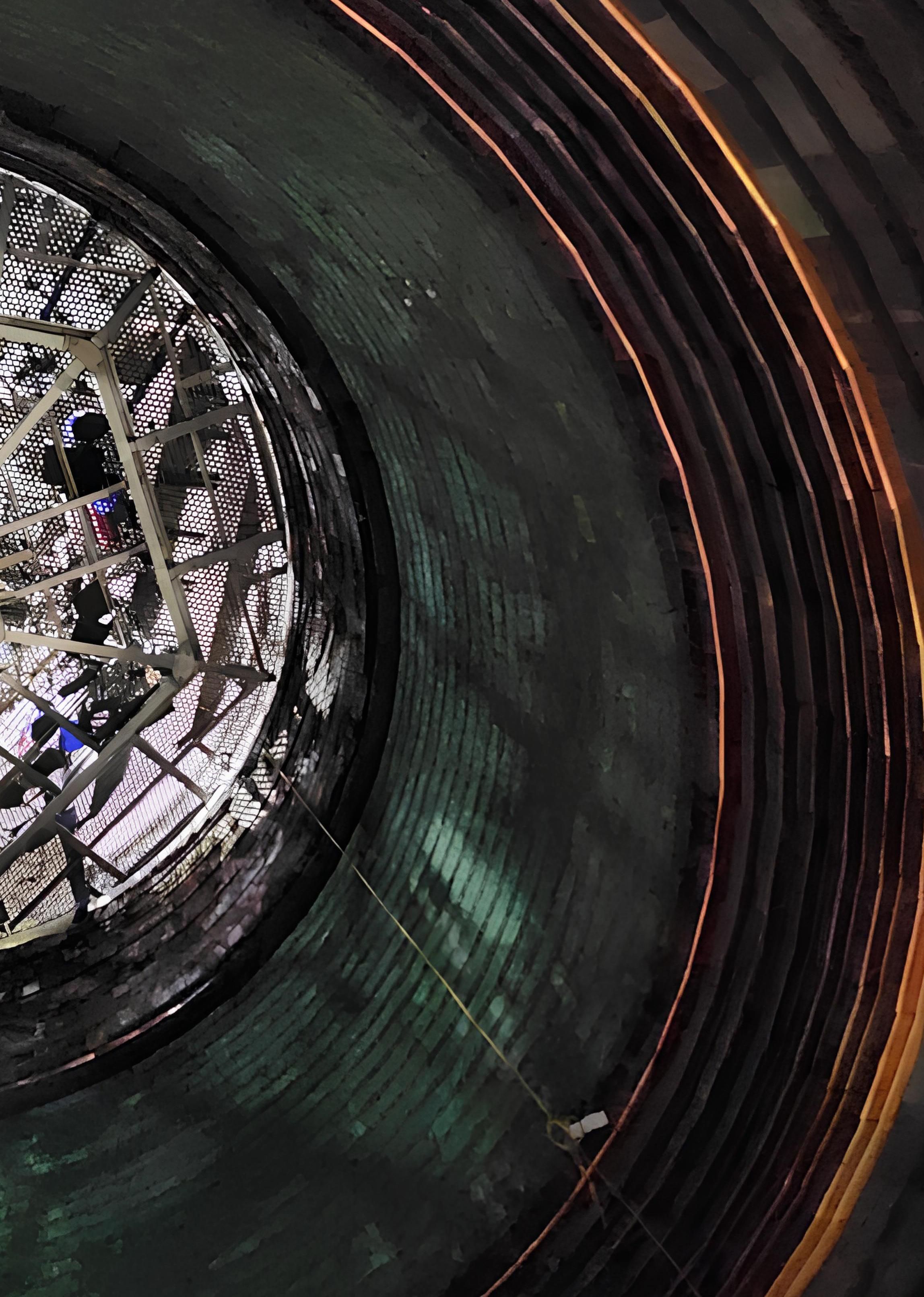
Katie Grube, a writer for the refractory, cement, packing, and lime industry, explains how a custom-engineered suspended platform revolutionised furnace refractory reinstallation, improving safety and efficiency during a shutdown project.
Always looking for ways to improve processes, Dave Drorbaugh II played a key role early in his career as a lead project manager at a metal processing facility. Dave was responsible for tactical and strategic process oversight, production forecasting, and project support. During that time, the facility conducted a major shutdown to rebrick one of their metal processing furnaces. The work required access to a 40 ft tall, 22 ft diameter vertical shaft. Time was tight, which meant Dave did not have the luxury of exploring alternative work platforms. In the end, the team decided to go with conventional scaffolding built off of a hanging static platform. The scaffolding system got the job done, but Drorbaugh and his team were aware there were more efficient options available.
A decade later in 2023, with furnace overhaul again scheduled, Drorbaugh, now a business unit manager at RECON Engineering & Construction, had the opportunity to participate in a full shutdown with the same smelter. The timeline of this project allowed the RECON team to improve upon previous efforts by commissioning a custom solution to increase access and safety for the refractory reinstallation project.
In 2014, the project required removal and reinstall of refractory in the lower half of the furnace shaft. The unit has a life cycle of 8 – 10 years. As a result of the long wait between projects, each shutdown is a new challenge where the team completing the project needs to consider new technology or methods, while remembering lessons encountered during prior rebuilds. The tight timelines in 2014 meant that there was insufficient time to explore nontraditional installation options. The project ended up relying on several levels of scaffolding and a static platform and faced multiple challenges.
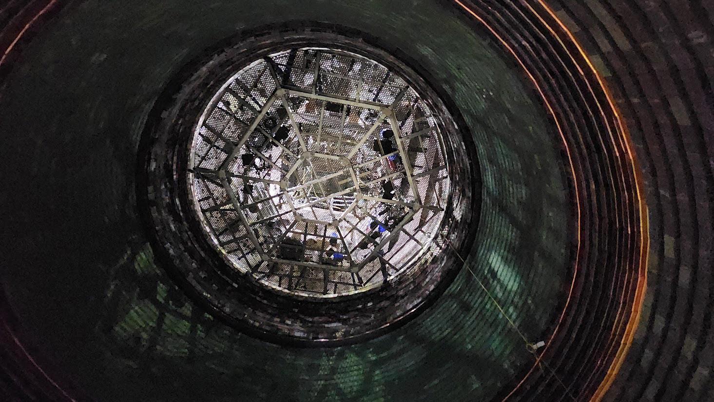
For this project, Bricking Solutions custom engineered a suspended platform with a 24 ft (7 m) diameter.
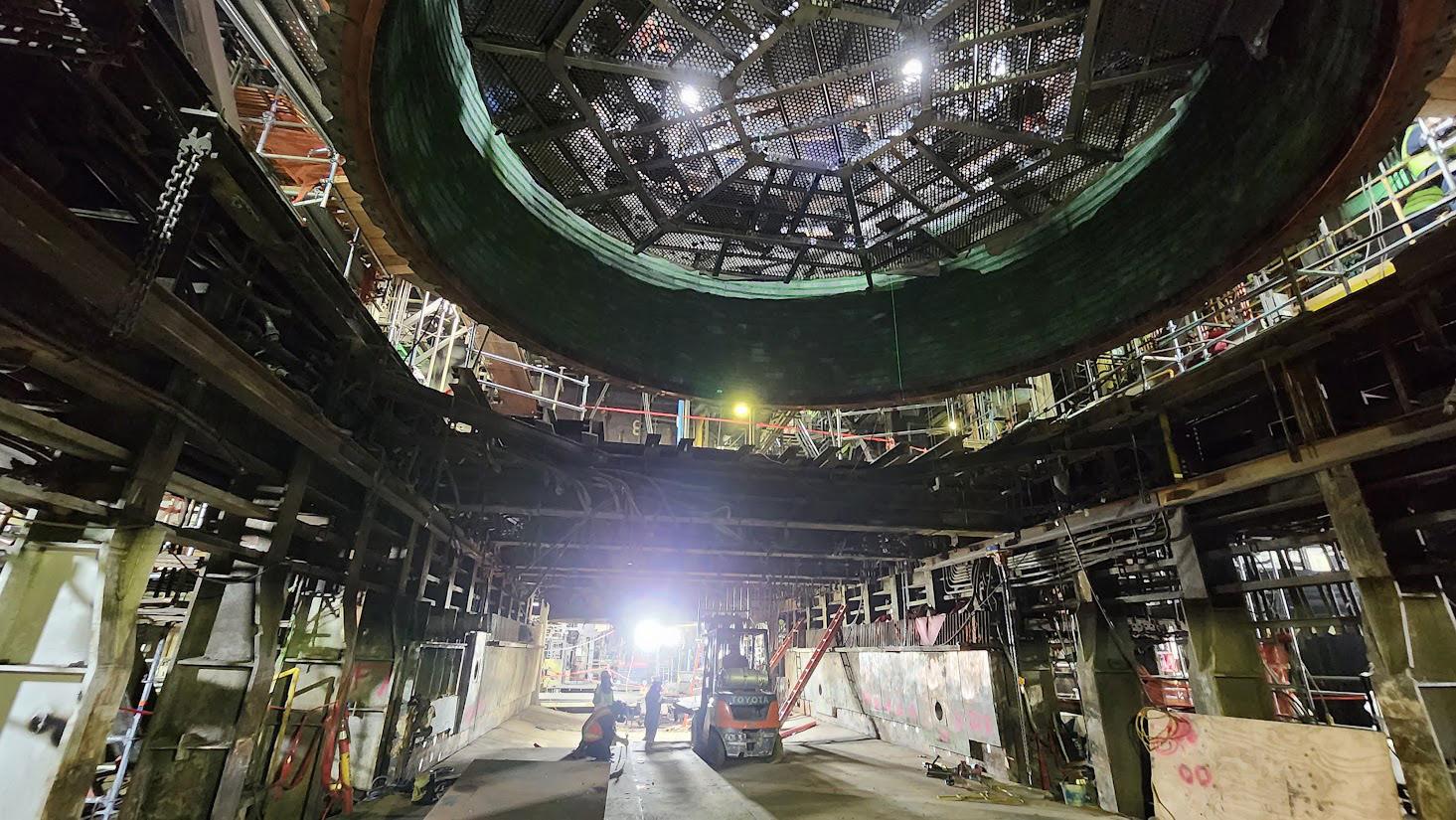
RECON’s crew of six worked on the platform removing the refractory brick and rebricking the upper half of the shaft while multiple construction teams worked below the platform, which was one of the major selling points for Drorbaugh.
The complexity of the scaffolding structure, including juggling a variety of pipes, hardware, boards, and other materials, meant setup required multiple shifts. The team also found that they could only reliably utilise two layers of scaffolding before the static platform started to sway and deflect. This was a workable solution for repairing the lower half, but adding height or weight would destabilise the entire structure, making it unsafe for crews.
When it came time to remove the scaffolding structure, the sections needed to be removed via a small, 1 by 1 ft port. However, removing swing scaffolding in this manner would put timelines at risk, with any delays resulting in six-figure production losses. In the end, the team decided it was more efficient and cost-effective to simply leave the framework in the furnace and melt it away.
“Scaffolding really became our only option 10 years ago. But we had a lot of logistical issues,” Drorbaugh said. “It became something of a loose end. But, with a longer timeline and a larger repair scope, RECON decided to look for a safer, more viable option for the 2023 shutdown.”
For the 2023 shutdown, the metal processing facility planned a complete redesign of the furnace shaft, creating more shell work and the need to do a full refractory reinstallation. When the facility contacted RECON, Drorbaugh knew, with more time, he could come up with a more financially beneficial installation option for the project than the scaffolding used in 2014.
In the years following the shutdown a decade earlier, the RECON team continued looking for ways to make refractory removal and reinstallation faster and easier. When given the opportunity to participate in the 2023 shutdown, the team’s prior experience and knowledge of Bricking Solutions, an equipment manufacturer specialising in custom refractory installation equipment, paid off.
RECON knew the team needed a stable, safe equipment platform and started looking into custom-built options. This naturally took them to Bricking Solutions. For this project, Bricking Solutions custom engineered a suspended platform with a 24 ft (7 m) diameter. Bricking Solutions worked with RECON to provide the facility with specs and an official rated capacity. The base metal processing facility agreed the addition of a suspended platform was the best option for the job.
The KROSAKI Group, through the Krosaki AMR Refractarios and Refractaria factories in Spain, supplies the most complete range of high quality refractory materials for the cement industry.
Over a century of QUALITY and INNOVATION in refractories for the CEMENT INDUSTRY
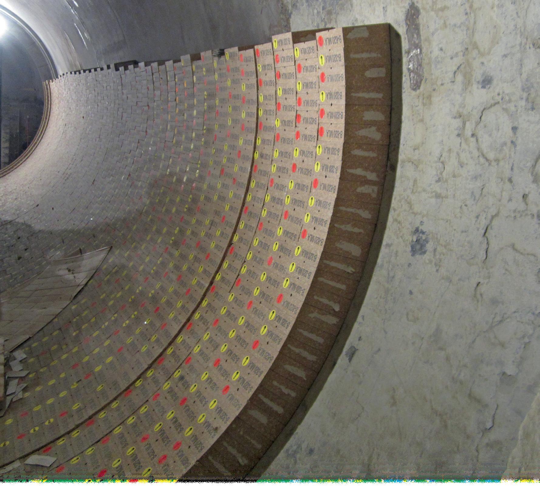
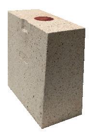
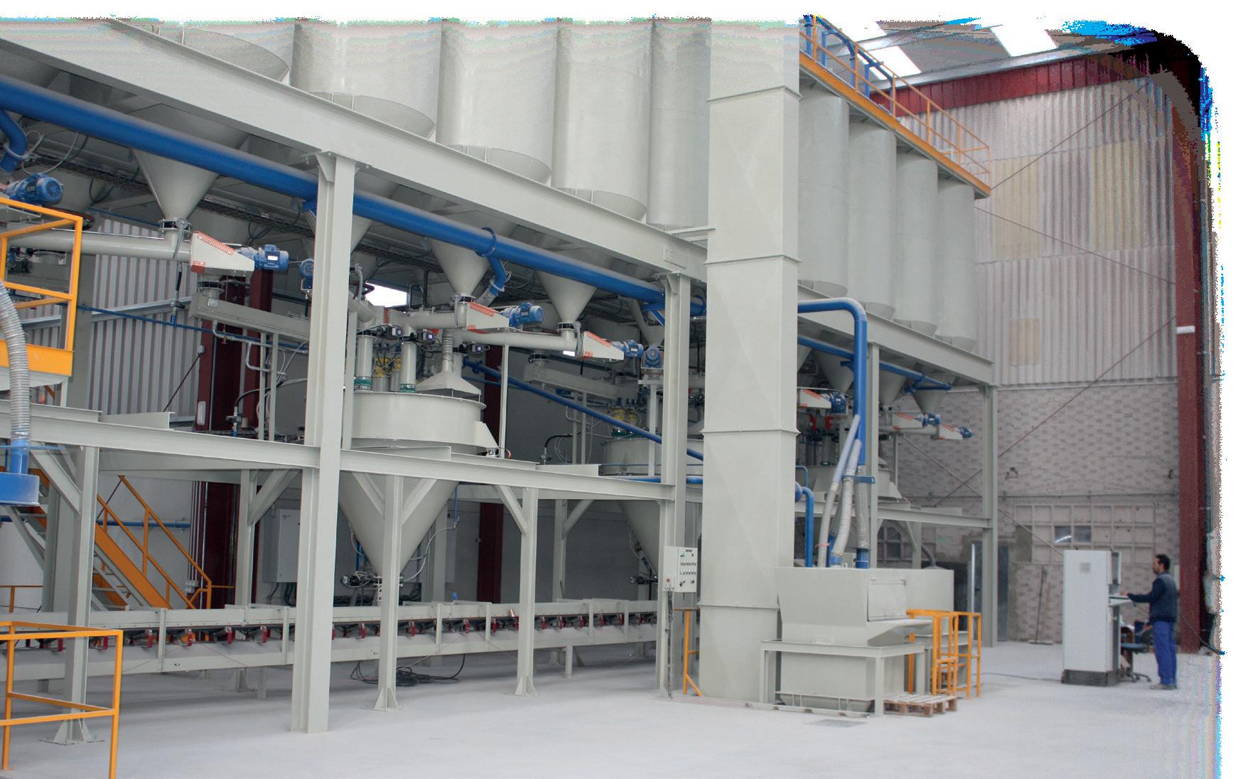
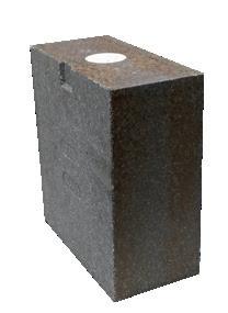
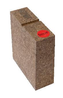
www.krosaki.amr.com www.refractaria.com
“We were looking at ways we could potentially improve upon what was done 10 years ago, something faster and quicker that facilitated parallel work fronts, that sort of thing. From a safety standpoint, the suspended platform was a turnkey engineered solution instead of something homegrown. We were able to purchase and roll it out,” Drorbaugh said. “We submitted this product in our use plan for approval. Because there was documentation and it came on letterhead, it made the approval process more straightforward and gave our team the confidence to get to work.”
The first step in getting the facility ready for the suspended platform, roof prep, was simple and required minimal setup. The facility already had a beam framework in place. All the RECON team needed to do was set the support beams on top of the existing framework and tack them down.
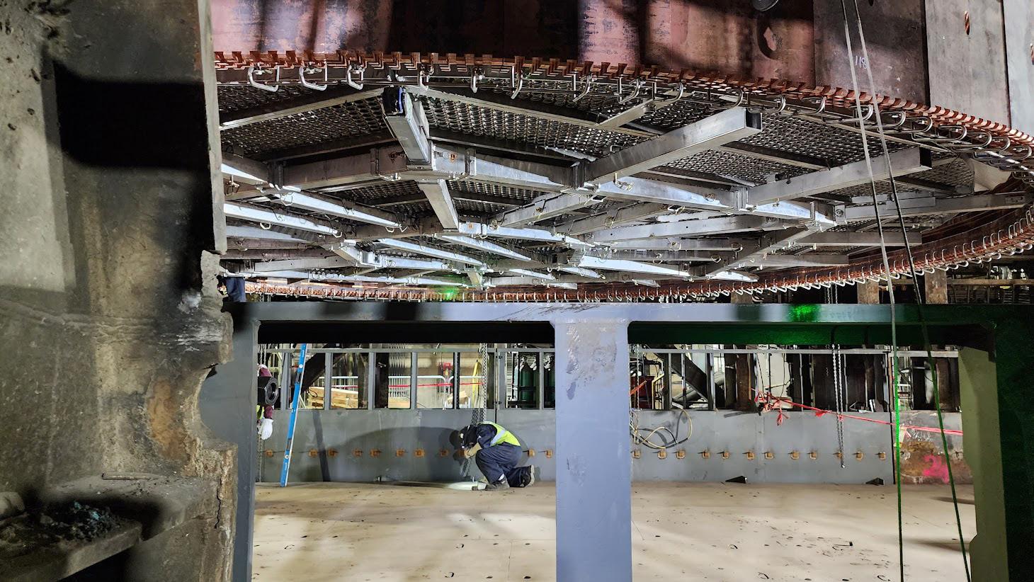
“We were looking at ways we could potentially improve upon what was done 10 years ago, something faster and quicker that facilitated parallel work fronts, that sort of thing. From a safety standpoint, the suspended platform was a turnkey engineered solution instead of something homegrown. We were able to purchase and roll it out,” said Dave Drorbaugh II, business unit manager at RECON Engineering & Construction.
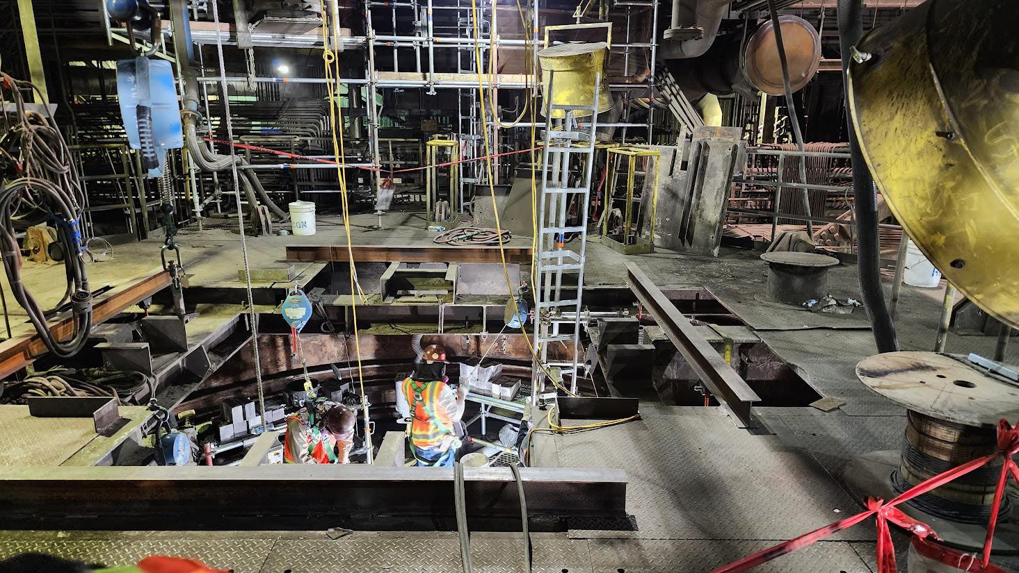
The EZ lift platform is made of high-strength 6061-T6 aluminium, providing the same strength as steel at a third of the weight. More importantly, the modular construction means pieces are easy to manoeuvre, weighing 40 lb (18 kg) or less, and fit through a 22 in. (560 mm) diameter access hole. The pieces easily passed through available access ports, allowing for rapid, straightforward assembly.
The pin-together construction greatly reduced the number of components and tools required for erection and allowed complete platform assembly in about three hours.
RECON’s main responsibilities encompassed demolition and reinstallation of the refractory lining. The hearth included three layers of brick with a 4 ft (1.2 m) depth while the shaft required only one layer of refractory brick and one layer of ram. The crew began the project by demolishing the bottom portion of the smelter with Brokk demolition machines before scaling the shaft clean. A mechanical crew then started rebuilding the shaft.
Halfway through the rebuilding efforts for the bottom part of the shaft, RECON put together a temporary bulkhead to provide a stable base while building the platform.
The size of the platform and the overall working height being 50 ft (15 m) meant the crew ran into smaller electrical issues they needed to troubleshoot on site before lifting the platform into place. After this initial challenge, RECON was able to position the platform higher in the shaft, out of the way, while the initial demolition and reconstruction was completed. They lifted and lowered the platform itself via six rented hoists attached to the beam framework at the top of the shaft. Once the electrical issues were dealt with and the platform constructed, the team dropped out the supporting bulkhead so the bottom third of the shaft could be completed.
RECON’s crew of six worked on the platform preparing the shell steel and rebricking the upper half of the shaft while multiple construction teams worked below the platform, which was one of the major selling points for RECON.
The RECON team completed shell prep of the shaft via rivet busters and needle gun scalers from the EZ lift platform. To safely raise and lower the brick, RECON paired the EZ lift platform with a material handling basket, which was operated by a hoist positioned one level above the suspended
platform support beams. By the time the furnace refurbishment was completed, the team installed over 2000 t of material, with 260 t of this material being in the shaft in question.
RECON then started rebricking the interior of the shaft. They needed to keep the weight on the platform below 4000 lb, so they limited the brick being brought up to the platform to 1000 lb (454 kg) increments to ensure the total weight on the platform never exceeded that number.
Once crews completed the brick installation at the top of the shaft, the mechanical crew and RECON’s team switched places so they could work on the hearth and lower levels of the shaft. “The suspended platform allowed us to facilitate multiple work fronts and worked as a support for the mechanical and structural work at the top of the shaft once we moved to refractory work on the hearth,” Drorbaugh said. “While the platform started out being used for the refractory installation team, it ended up being a work platform for various mechanical and structural crews that needed to work up top, too. In fact, to make sure we weren’t interrupting the workflow of the mechanical crew, we left the platform set up in the shaft for an additional month after rebricking finished before lowering it down and disassembling the structure.”
The RECON team took apart the suspended platform and removed it from the furnace by hand over a single shift change, minimising any impact to the ongoing work in the furnace. RECON estimated that the teardown time for the platform required about a quarter of the time a traditional scaffold system might require. The custom-built EZ lift platform and material basket were such a success that the base metal processing facility kept the equipment for use in future shutdowns.
“On the tactical level, the EZ lift platform is a big success, both in terms of project logistics and safety needs,” Drorbaugh said. “The Bricking Solutions team remained in contact and ready to answer any questions throughout the project. We weren’t left to flounder if we did come across any issues. Thankfully, with the onsite training Bricking Solutions provided, we didn’t run into any structural issues with the platform and the rebricking proceeded nicely.”
About the author
Katie Grube is a content writer with over five years of experience for the cement, refractory, packing, and demolition industries. Kate enjoys learning about innovative equipment and services and communicating the ways they help improve profitability, safety, and quality.

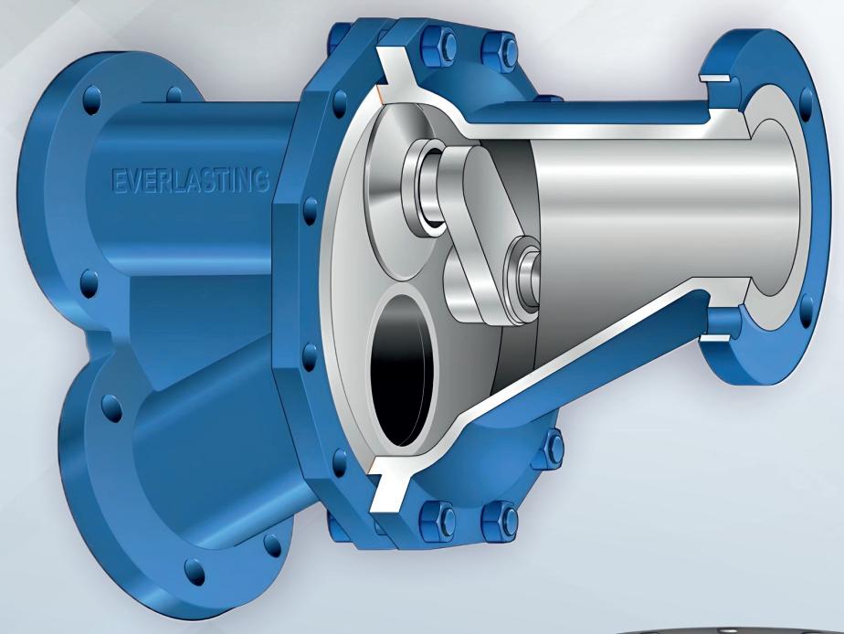

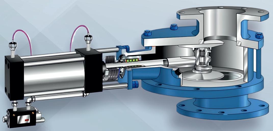


Steve Klein, IAC, outlines how targeted interventions can optimise baghouse performance in just 24 labour hours.
Baghouse dust collectors play a crucial role in ensuring safety and cleanliness in cement plants and other industrial processes. When these systems underperform, they can lead to costly downtime, regulatory non-compliance, and reduced equipment lifespan. However, many cost-effective and time-efficient solutions can enhance performance without requiring a full system replacement. With targeted interventions, operators can achieve noticeable improvements in just 24 labour hours.
Before making any adjustments, it is essential to identify the possible modes of failure that may be affecting the operation of a specific baghouse. These modes of failure are:
Pressure (differential)
Baghouses are designed to move a predetermined amount of air. This amount of air is determined by the required ventilation of the given process the baghouse is ventilating. Assuming that certain operating parameters are accounted for in the baghouse design (i.e., internal velocities, avoidance of high-abrasion design characteristics,
limited access), high differential pressure can become uncontrollable, resulting in the need to frequently replace filters to maintain draft in the process.
Dust collectors, by design, want to operate at a very steady and controlled pressure point. While differential pressure and airflow can change with a variable speed fan, the overall system wants to stay at a single point, as determined by the fan, fan motor, and the overall resistance to airflow it must overcome. High differential pressure leads to lowered airflow, reduced ventilation, and eventually failure.
The majority of baghouses operating globally are 'high pressure low volume' cleaning systems. While these
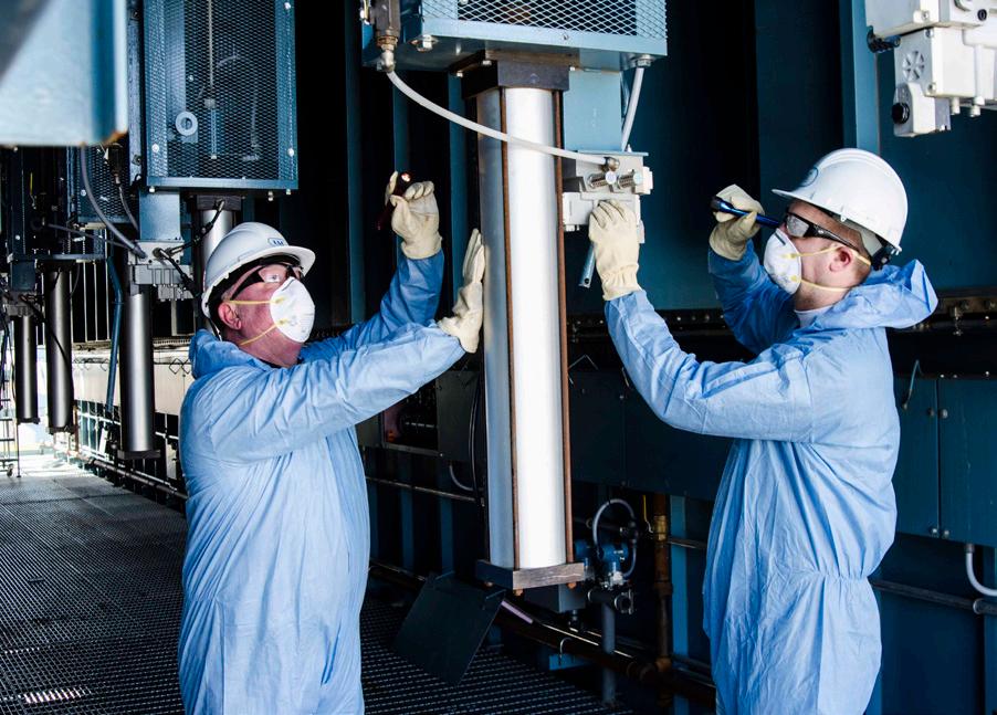
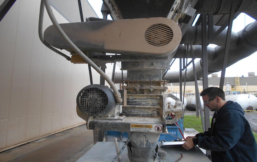
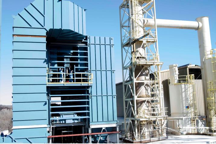
systems do not consume a large amount of air per pulse, they do require that the available compressed air be high-pressure (i.e., minimum ~75 psi). When high pressure air is unavailable, baghouse cleaning systems will underperform, leading to increased differential pressure and its associated symptoms. If leaks in the compressed air system exist, they create availability issues, operational cost increases, and worsening performance in the baghouse itself.
Conveyed air stream in any manufacturing facility can range from ambient temperature to above 400˚F. Various components in baghouse design have associated temperature limitations (i.e. gaskets, paint, filter media). If a baghouse circuit operates above these temperatures, it will degrade fabric strength, damage gaskets, allow infiltration of outside air, lead to hole formation in the filter, and eventually allow escaping emissions and downstream equipment damage.
Any unplanned and repeating mechanical issue can lead to failure in a baghouse circuit. Mechanical issues may go undetected for days, such as excessive vibration on fan or motor parts. Unfortunately, mechanical failure also occurs with proper operation of baghouses. The cleaning function of any baghouse type (pulsejet, reverse-air, plenum pulse, or other) will eventually weaken the fabric used to construct the filters. This occurs even when everything is designed according to best practices and operational recommendations from quality equipment suppliers. Simply put, moving parts fail. As a rule, ten years of using a pulse jet cleaning system reduces its operational efficiency by 50% due to mechanical wear.
Chemical
While not as common and sometimes difficult to diagnose, chemical failure can occur in many baghouses. It frequently manifests as filter media hydrolysis from elevated temperatures with high moisture content. It can also occur with increased frequency in 'hot' baghouses (mill, dryer, calciner) that pass through the dew point frequently. If this is managed incorrectly, water vapour can become water droplets in the baghouse, impacting fabric strength, dust cake release, and escaping emissions.
As a concept, what can be done with 24 hours of labour to troubleshoot problematic baghouses?
Quick inspections or actions (under one hour)
f Do the gauges and instrumentation work? Gauges (differential pressure, static pressure) are crucial and should be replaced if malfunctioning. If these pressure readings are not known it will be difficult to troubleshoot. Redundant DP gauges


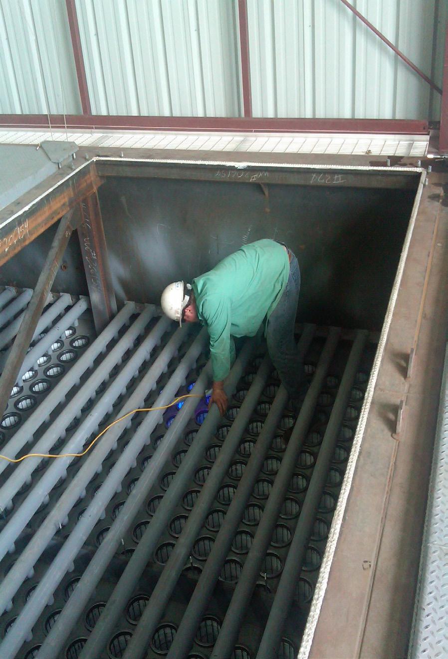
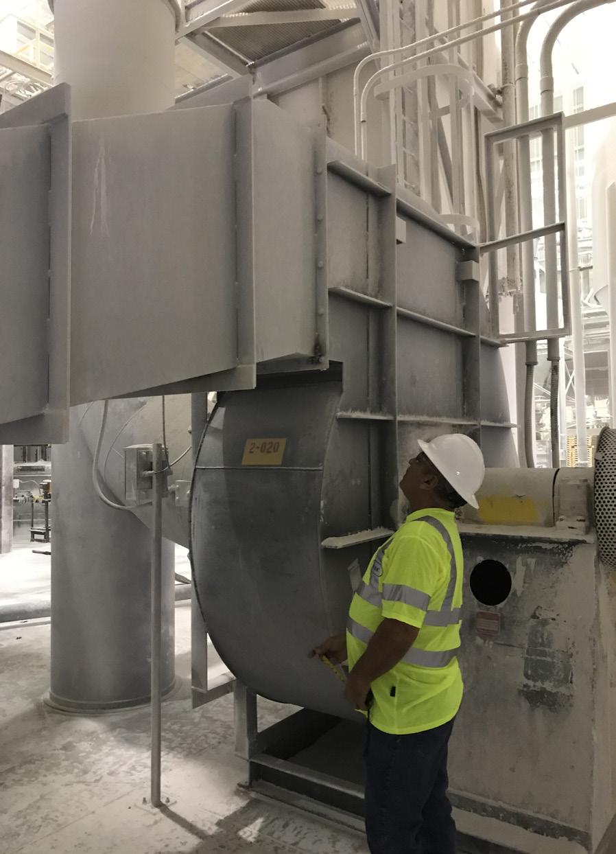
can be installed at grade easy access with air tubing running to both the dirty and clean side of the tubesheet. Knowing these readings is similar to the 'check engine' light in a car; it needs to be checked out before it becomes a bigger problem.
f Inspect hopper for buildup: hoppers are designed for material transport, not storage. Material buildup can lead to re-entrainment, causing abrasion and reducing filter bag lifespan. Solutions include discarding excess material or using a day bin, adjusting airlock or screw conveyor operation, or applying material handling aides to hoppers that refuse to discharge dust.
f Is the correct filter and cage used? Ensuring a snug bag-to-cage fit enhances cleaning efficiency and prevents premature failures. Use pie tape and calipers to measure and maintain optimal 'pinch' of the filter media in relation to the cage. To determine the 'pinch', measure the cage diameter, then subtract the bag diameter. If there is no 'pinch' the filter may not be able to clean. If there is too much pinch, the filter may fail from flex fatigue from too much movement against the cage.
f What is the condition of the blowpipes? Blowpipes must be horizontally and rotationally centred with each tubesheet hole proper operation. Correctly aligned blowpipes prevent fabric damage and maximise cleaning efficiency. Blowpipes must be inspected to ensure they remain uniform, as wear can create ineffective teardrop shapes in each orifice.
f Is the screw conveyor operating correctly? Screw conveyers should be designed to move product to a single discharge point away from the inlet at a predetermined speed. Upon inspection, if the screw is moving material toward the gas inlet, the likelihood of re-entrainment increases as material piles refuse to discharge from the hopper. Reversing the direction of the screw conveyor away from the inlet will move material away from the gas inlet. This prevents fewer airborne particulates from becoming re-entrained into filters, extends bag life, and reduces wear on screw conveyors. Inspecting for this condition is quick and highly recommended.
f Is the baghouse history known? Maintaining detailed records of baghouse inspections and repairs will reveal performance trends, lead to optimised maintenance schedules, and reduce long-term costs. Considerations for documentation and monitoring in baghouses include operations, daily pressure readings, loading, bag failure maps, and bag life trends. If short on labour, IoT gateways, such as a Smart Plant™ system, are recommended for automated data acquisition of critical signals (i.e. pressure, emissions, level indication).
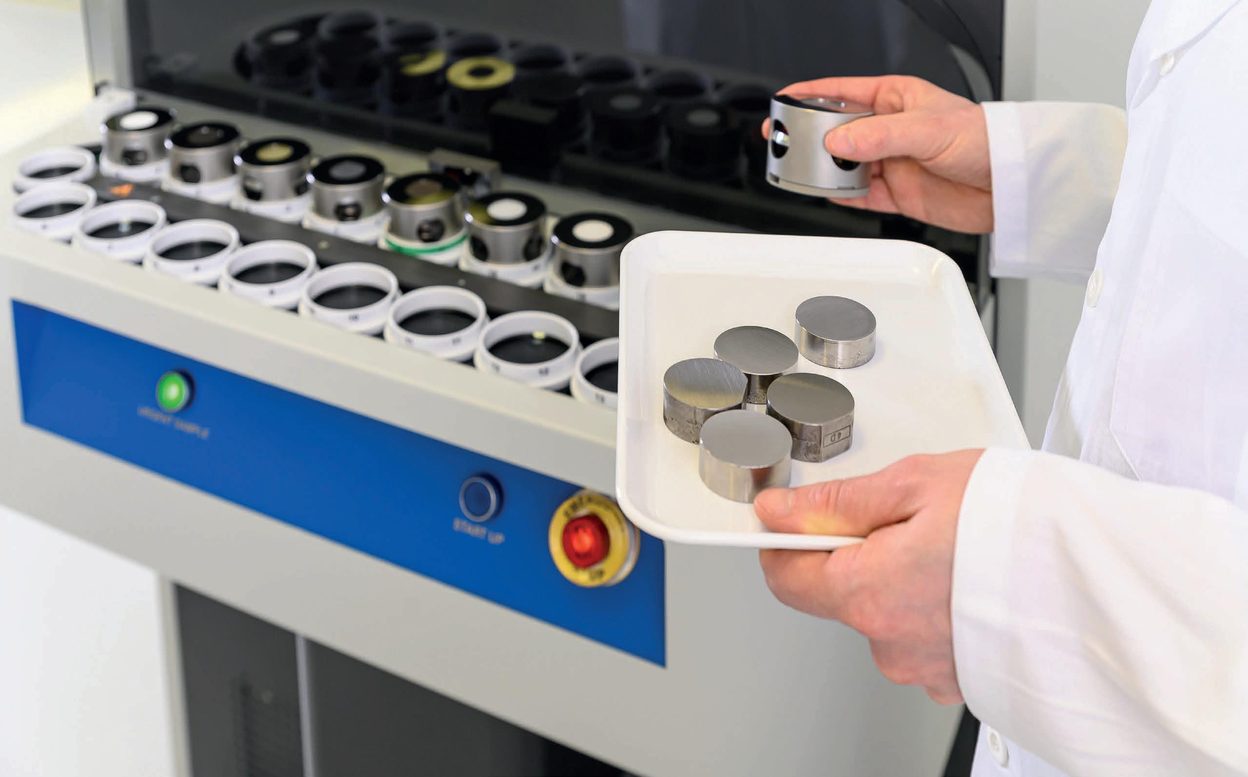

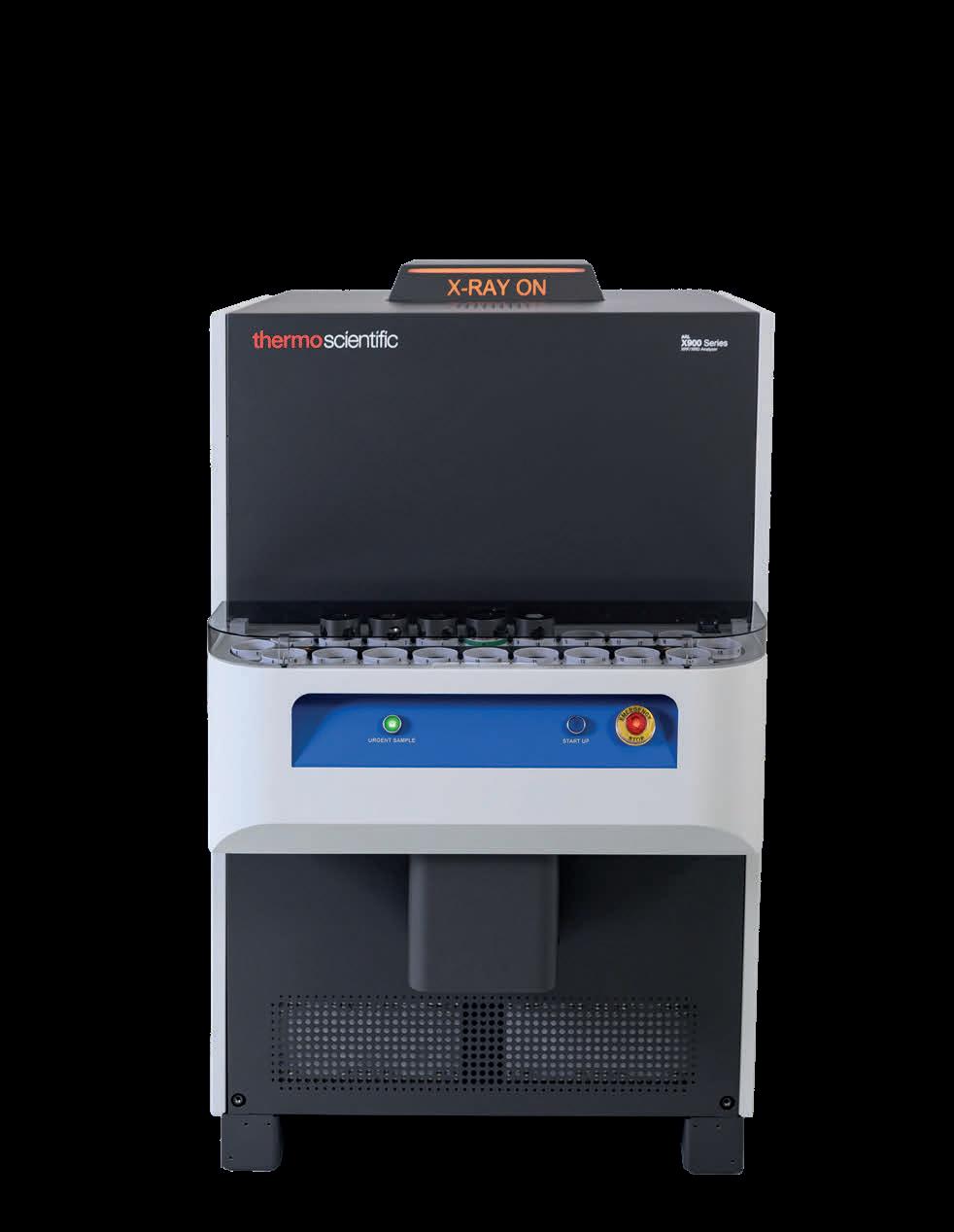

f Is everything buttoned up? Every time an access door is opened and closed on a baghouse, the seals around that opening degrade and begin to wear out. Doorseals must be replaced with regularity to eliminate in-leakage of outside air, negative system heat loss, and metal corrosion associated with condensation. Make sure the correct doorseals are used as their shape, material, and size vary depending on door design. All associated hardware associated with an access door must be in good condition to create a strong seal. Use a putty knife and a wire wheel to remove buildup around the door before installing new doorseal.
f Can a filter bag be tested? Testing a removed filter in a laboratory setting is the best way to confirm changes in filter media. A reputable testing lab will test for media strength, flex cycles, air permeability, and thermal or chemical degradation. This information can be used to examine current operational conditions and contribute to recommended changes to extend filter life.
More work is required (half a day)
f Is the pulse-jet system optimised? Differential pressure in pulse-jet collectors must be reduced by rearranging the structure of the dust cake on filter bags. Too dense of a dust cake structure will cause higher differential pressure and resistance of airflow. If the baghouse cleaning system fires its solenoids sequentially, consider rearranging the solenoid outputs to a 'staggered' sequence. Staggered pulsing minimises dust reentrainment. Reprogramming the pattern on the timer card from a sequential to a staggered sequence, where it skips two or more rows, will minimise re-entrainment of dust as it returns to rows previously cleaned. Clean with a crisp pulse set at an adequate duration, usually 100 milliseconds. Anything more is waste and increased cost in a high pressure cleaning system. Off-time between pulses must exceed the recovery time of the air manifold to ensure effective cleaning energy with every pulse.
f Are the filters installed correctly? When installing filter bags, mechanic seal of the filter-to-baghouse connection will only occur when installed correctly. Recommendations change based upon baghouse design, but escaping emissions will always occur if filters are incorrectly installed. Additionally, ensure all seams are oriented in the same direction. This will establish a reference point to troubleshoot abrasion or other modes of failure. Older baghouses have unique filter construction that may require special considerations upon installation (i.e. flanged filters, twist-locking venturis, or double cuffed tops). For bottom-load bags, the seams should
be placed opposite the gap of the cage collar and the clamp should be 90˚ from the bag seam to prevent puckering of media.
f Can leak detection powder be used? It is easy to locate air leaks within the baghouse by using leak detection powder. Once injected, the fluorescent powder finds the path of least resistance (i.e. holes in filter, cracks in baghouse, incorrectly installed filters) and accumulates in that area. A black light will allow the leak detection powder to illuminate and show the severity of the leak (Figure 4). Once located, the leaks can be repaired, or filter bags replaced. A second leak test can be performed with a powder of a different colour to confirm repairs were effective.
f Can the filters be conditioned? Injecting a pre-coat conditioning agent onto newly installed filters can protect them from hydrocarbons or agglomeration at start-up associated with moisture and desiccant carryover. It adds a primary, artificial porous dust cake to the surface layer of the bags which increases cleanability and aids in avoiding initial filter blinding. These conditioning agents should be applied as a pre-coat to new bags following a changeout, or on a scheduled basis to keep operation of the baghouse as efficient as possible.
f Can pleated filter elements be used? Converting traditional filter bags to pleated filter elements increases filtration, lowers velocity, and increases control differential pressure. This conversion can be made within the same structural footprint and requires no mechanical changes. An engineer needs to calculate operating conditions for this to be successful. Once a baghouse is converted, pleated elements can add up to 3 times more filtration area, provide a lower air-to-cloth ratio, lower differential pressure, and elimination of mechanical failure via dust impingement of traditional filters.
f What is the compressed air like? Compressed air can be contaminated with moisture and desiccant. This results in pneumatic component damage, higher pressure drop due to improper cleaning, and clean-side contamination as dirty air is pulsed into the filter bags. To quickly upgrade a compressed air system, install a desiccant dryer, which uses desiccant material to absorb moisture from the air. To keep moisture from flowing to the bags from the manifold, install an auto purge valve (actuated by an existing solenoid) to pulse water out of the tank with each cycle.
f Has the system been inspected for in-leakage at pickup points? Take the time to walk the entire system and inspect all components for air in-leakage. This includes joints in ductwork,
airlocks, fans, and hopper or baghouse doors. Once a leak is located, use the proper repair or replacement technique such as silicone sealant, gasketing, new clamps, patch weld, rubber skirting, or adjustable seals such as ceramic adhesive tiles.
What can be done next during a 24-hour downtime?
f Change to a clean-on-demand system: baghouse controllers should have differential pressure gauges (or baghouse controllers with IoT capabilities) to determine when the baghouse should clean. When cleaning on demand, a pre-determined window of pressure is set to determine when the cleaning system will start and stop cleaning. Cleaning on-demand will eliminate overcleaning filters, which causes mechanical wear. The recommended window for cleaning on-demand is tight: 0.5 in. of pressure change between the dirty and clean side of the baghouse.
f Upgrade the cleaning system: diaphragms and solenoids mechanically fail. There are new and innovative diaphragms that are available and provide a massive upgrade in baghouse cleaning performance. Pulse valves can fail as the internal seating mechanism becomes eroded over time. Redesigned diaphragm valves increase the speed to fully opening and decrease the closing time, and both these factors improve high pressure low volume cleaning systems. If the cleaning system is undersized, the pulse valve can be changed to a double-diaphragm design. Double diaphragm valves provide more effective cleaning single diaphragm valves.They release a shorter, more crisp bubble of air as it travels down the entire length of the bags.
f What is the condition of the belts? Belts wear out within industrial manufacturing facilities. Compromised transfer points in belt conveying systems are all prone to leakage which, if unchecked, will starve the process from the needed draft. For belts, single point vent dust collection is beneficial (Figure 5). Inspect and fix any openings on enclosures, contact with conveyed material piles should be avoided. Note any spillage areas associated with this issue. Single point vent dust collectors on belt conveyors are low profile, eliminate the need for ductwork venting these transfer points, eliminate the need for a discharge device, and are relatively inexpensive. Additional process parameters need to be gathered for proper implementation
f What is the condition of the dampers? To control airflow as pressures change during grain loading, installation and use of a modulating damper is recommended. The damper
regulates the air velocity which increases near the end of grain loading as resistance is reduced. This helps eliminate smaller particulate from being forced into filter bags and it enters baghouse at higher-than desired velocity
f Is a full replacement needed? Baghouses will suffer from high pressure drops, corrosion, insufficient cleaning, and inadequate ventilation if not originally designed properly. When replacing capital equipment, consider overlooked factors such as grain loading, temperature, moisture, bulk density, and pH level of the dust. Partnering with an expert for evaluation of these factors is the best method for avoiding previous cost-cutting measures or under designed ventilation equipment.
f Have baghouses been connected via IoT gateway? Advanced diagnostic controls like IAC’s Smart Plant™ remote monitoring systems can detect the modes of failure, (i.e. failed solenoids, failed diaphragms, and leaking filters) far sooner than manual inspection methods. Other methods of improvement (i.e., pulse optimisation, valve condition, proper filter installation, compressed air usage, and advanced vibration monitoring) can be automatically and continuously validated with advanced diagnostics and IoT enabled technology. Consideration of IoT platforms for visual management of data decreases installation costs, improves personnel response, and simplifies plant record keeping. Ease of implementation and communication method (i.e., LoRaWAN, 5G Cellular) expedites reliable results and adoption.
Optimising baghouse performance does not require extensive downtime or costly system overhauls.
By implementing strategic, cost-effective solutions, plant operators can achieve significant performance improvements in as little as 24 labour hours. From quick adjustments like blowpipe alignment and bag-to-cage fit to more advanced upgrades such as pleated filter elements and IoT gateway systems, these enhancements deliver measurable results.
Beyond immediate benefits, these proactive maintenance strategies extend filter life, reduce energy consumption, and minimise unplanned downtime – ultimately driving operational efficiency and cost savings. As environmental regulations tighten and production demands increase, maintaining a well-functioning baghouse is more critical than ever for ensuring compliance, safety, and long-term profitability.
By addressing common pain points and applying tailored solutions, operators can ensure their facilities remain clean, safe, and competitive in today’s challenging industrial landscape.

Ian Saratovsky, Gerald Hunt, and Travis Reynolds, Lhoist North America, explore key strategies for optimising HCl and SO2 abatement in cement production.
The manufacture of portland cement manufacturing results in emissions of gaseous pollutants, including SO2, hydrogen chloride (HCl), and mercury (Hg), which are released during the heating of the raw materials and the firing of solid fuels inside the kiln. Across the US and worldwide, portland cement production facilities are required to control acid gas and mercury emissions due to limits dictated in their operating permits, consent decrees, and/or other
regulatory mandates. Specific to portland cement manufacturing in the US, the National Emission Standards for Hazardous Air Pollutants (NESHAP) provides numerical limits for the emissions of particulate matter, hydrocarbons, dioxins/furans, mercury, and HCl. Hydrated lime dry sorbent injection (DSI) offers a cost-effective solution to comply with these regulatory requirements. During
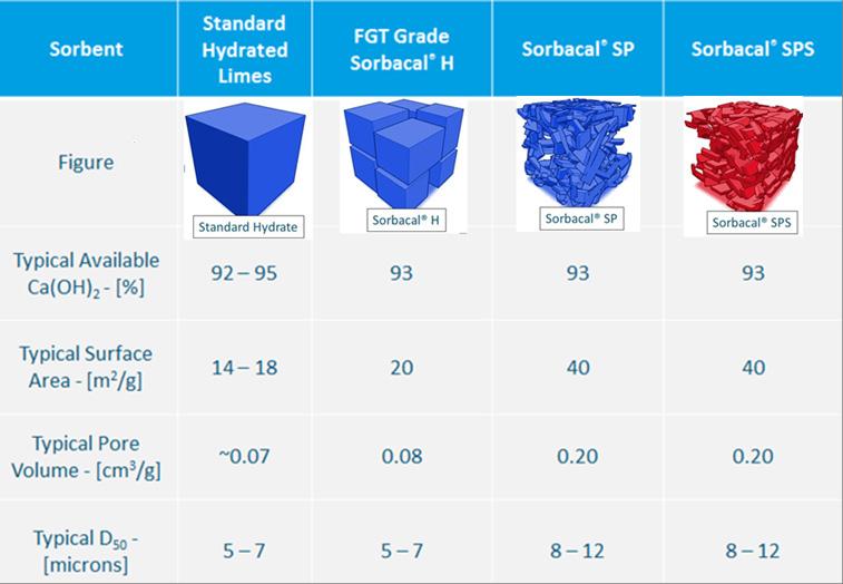
1. Physical and chemical properties of various hydrated lime sorbents.
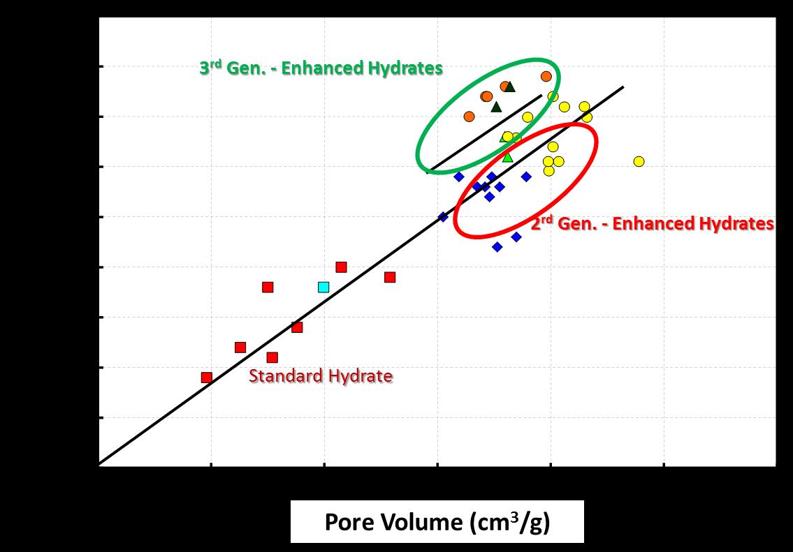
Figure 2. Impact of sorbent physical properties on SO2 capture. Pore volume and surface are the two key performance indicators for hydrated lime products.
the DSI system design phase, careful attention must be paid to sorbent selection, sorbent application location, and sorbent distribution into the gas stream to maximise the DSI system performance. In this article, various critical aspects of system operations and optimisation are discussed to achieve the lowest overall cost of compliance.
System capital expenditure
DSI and activated carbon injection (ACI) are two mature and relatively low capital technologies for acid gas control and vapour-phase mercury reduction, respectively. Both Hg and acid gas control sorbents have proven effective in a variety of industrial plants (i.e. utility, biomass, cement, waste incinerators, etc.) and have been used commercially in Europe and the US for over 25 years. Trial results from a past HCl test campaign with CEMEX and Lhoist North America were detailed in a previous World Cement article.1 DSI and ACI injection systems usually consist of storage (either silo storage or bulk bag, i.e. ‘super sack’) after which product is metered into an air stream and conveyed via dilute-phase into the process gas stream, upstream of a particulate collection device. However, while often considered a low capital solution relative to other acid gas scrubbing technologies, the greatest capital associated with DSI and ACI is the initial equipment procurement and installation. For applications where mercury control is either intermittent or low injection rates are needed, a blended hydrated lime (HL) and powdered activated carbon (PAC) sorbent allow for a single feed system to be used. For example, Lhoist’s blended HL-PAC product enables concurrent acid gas and Hg control using a single sorbent injection system (versus installing and maintaining two nearly identical systems), injecting the sorbents simultaneously as a pre-blended,
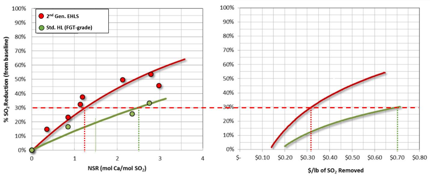
Figure 3. SO2 Reduction : Sorbacal® SP (2nd generation EHLS) vs. standard hydrate. Sorbacal SP (2nd generation EHLS) resulted in a 54% reduction in sorbent usage over a standard hydrated lime.
Cement Terminals

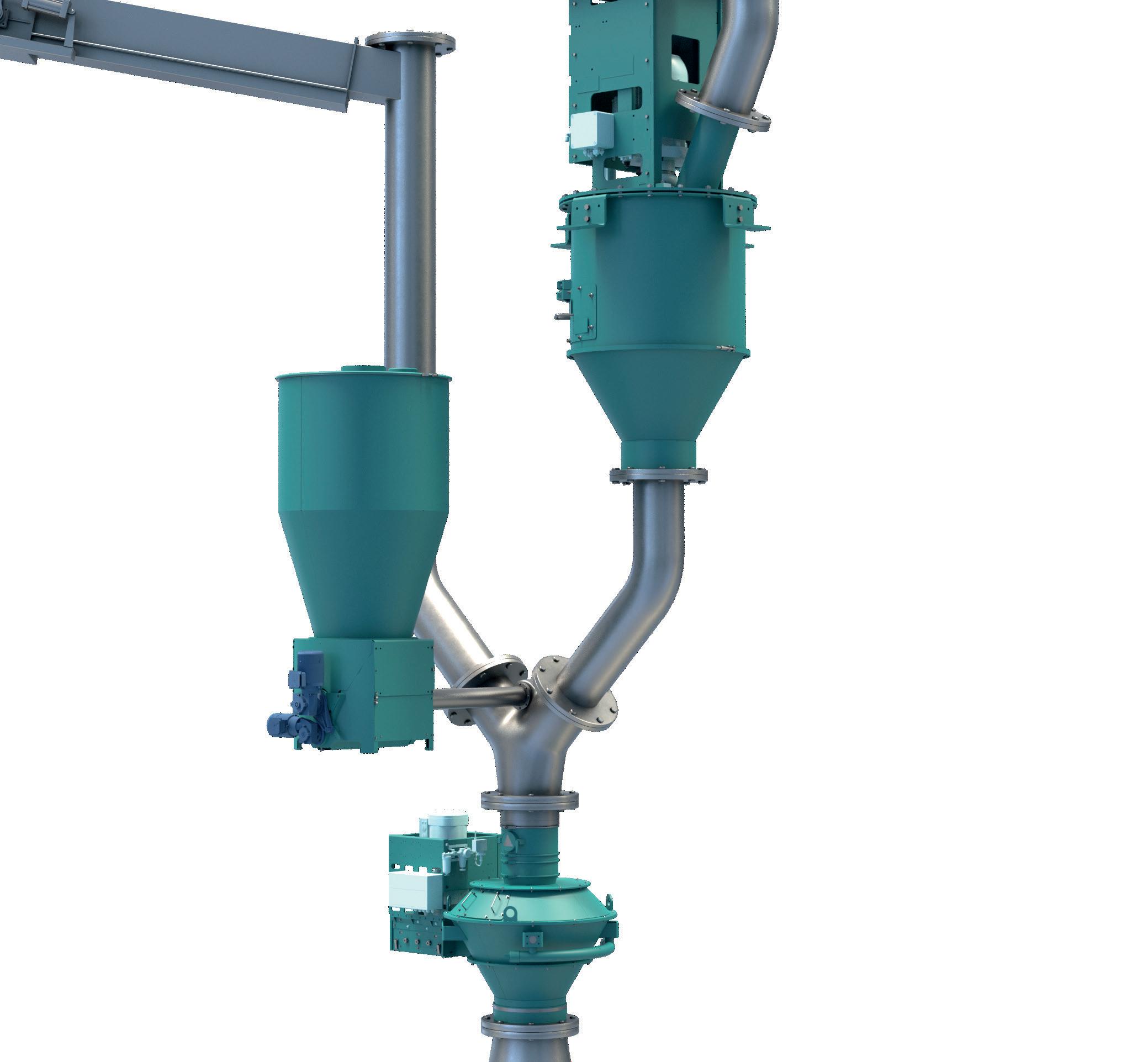
homogeneous product. Lhoist produces customised, enhanced hydrated lime (branded Sorbacal® SP and SPS) blended with brominated PAC in either bag or bulk, in 5% PAC (w/w) blend increments up to 20%.
Optimising operating expenditure
While a single, blended sorbent for Hg and acid gas can decrease overall system capital expenditure by reducing the need to a single system, careful attention should be paid to optimising the quantity of sorbent required to achieve compliance. DSI system design guidelines are discussed in detail elsewhere.2, 3
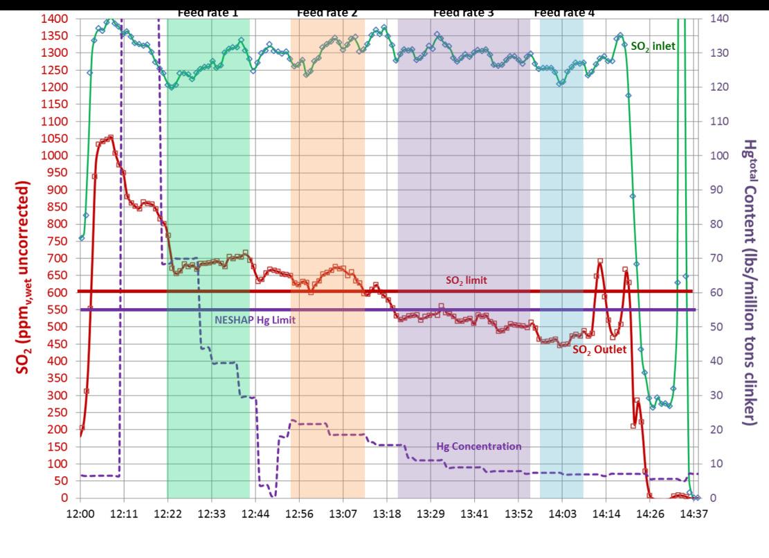
Figure 4. Simultaneous SO2 and Hg abatement with Sorbacal SP-PAC blended product. Acid gas emission measurements by FTIR were simultaneously conducted upstream of the injection lances (i.e. 'SO2 inlet' – green trace) and at the inlet to the baghouse filter (i.e. 'SO2 outlet' – red trace) to provide instantaneous performance even with variable process conditions. Hg was measured by CEMs at the stack (dashed purple trace). The relative quantity of PAC blended with Sorbacal can be custom-tailored (between 5% and 30%) to meet specific needs.
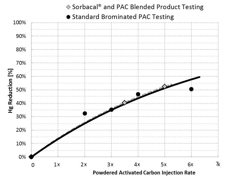
Figure 5. Hg reduction with Sorbacal – PAC blended product compared with a standard brominated PAC. Blending PAC with Sorbacal hydrated lime products does not alter PAC performance.
The focus of this article is to provide sorbent selection and sorbent application guidelines to achieve the most operationally cost-effective DSI programme. To this end, prior to equipment design and selection phases (or after system commissioning, if this was overlooked during design), plants should consider: optimal injection location (depends on target pollutants), sorbent type, and sorbent application/distribution within the gas stream. Sorbent trials with temporary DSI systems are highly recommended before the system design and selection phases, or to evaluate alternative injection locations after a DSI system is installed. Sorbent trials should include measurement of dose-response (i.e. parametric) curves at several different locations within the plant to identify the most efficient injection strategy. DSI programme design considerations to minimise operating costs:
f Sorbent type – standard hydrated lime?
Enhanced hydrated lime? Hydrated lime blended with powdered activated carbon (PAC) for simultaneous acid gas and Hg abatement?
f Injection location – sorbent injection at kiln inlet? Gas conditioning tower inlet? Gas conditioning tower outlet? Baghouse inlet? ID fan inlet? Abatement of HCl and SO2 often requires different injection locations.
f Injection lance type and configuration – standard pipe lances? Advanced sorbent distribution technologies? Static mixing lance designs? Dynamic mixing lance designs?
Over the past twenty years, calcium-based sorbents have evolved, driven by the need to improve acid gas capture efficiencies. Realisation of the importance of physical properties, such as particle size distribution, pore volume, and surface area, led to the development of enhanced hydrated lime sorbents (EHLS). These properties were engineered to create more reactive hydrated lime sorbents. Sorbent physical properties directly impact material handling properties and acid gas removal performance, ultimately dictating annual operating expenditures. Figure 1 compares Lhoist’s commercially available hydrated lime sorbents and their typical properties. Lhoist’s EHLS products are branded Sorbacal, the 2nd generation product is Sorbacal SP, and the 3rd generation is Sorbacal SPS. Sorbacal SPS is a chemically-activated formulation of Sorbacal SP, specifically designed to provide best-in-class acid gas capture performance. Figure 2 demonstrates the evolution of EHLS product physical properties and resultant impact on SO2 capture efficiencies. Pore volume (and indirectly, surface area) is the key performance driver for acid gas capture. While not
Each Vortex component is appropriately selected to meet the demands in every application. With an in-house team of engineers, Vortex product designs can be completely customized for individual applications or special installations. Vortex understands the value of your process. Our team of application engineers have more than 150 years of combined dry material handling experience. Vortex’s knowledge of handling dry material characteristics in pneumatic, vacuum and gravity flow applications is unsurpassed. Vortex delivers intelligent, cost effective solutions for all dry bulk materials. No application is too large, too small or too difficult to handle.
Solids & Bulk handling components engineered to keep your system up and running. www.vortexglobal.com
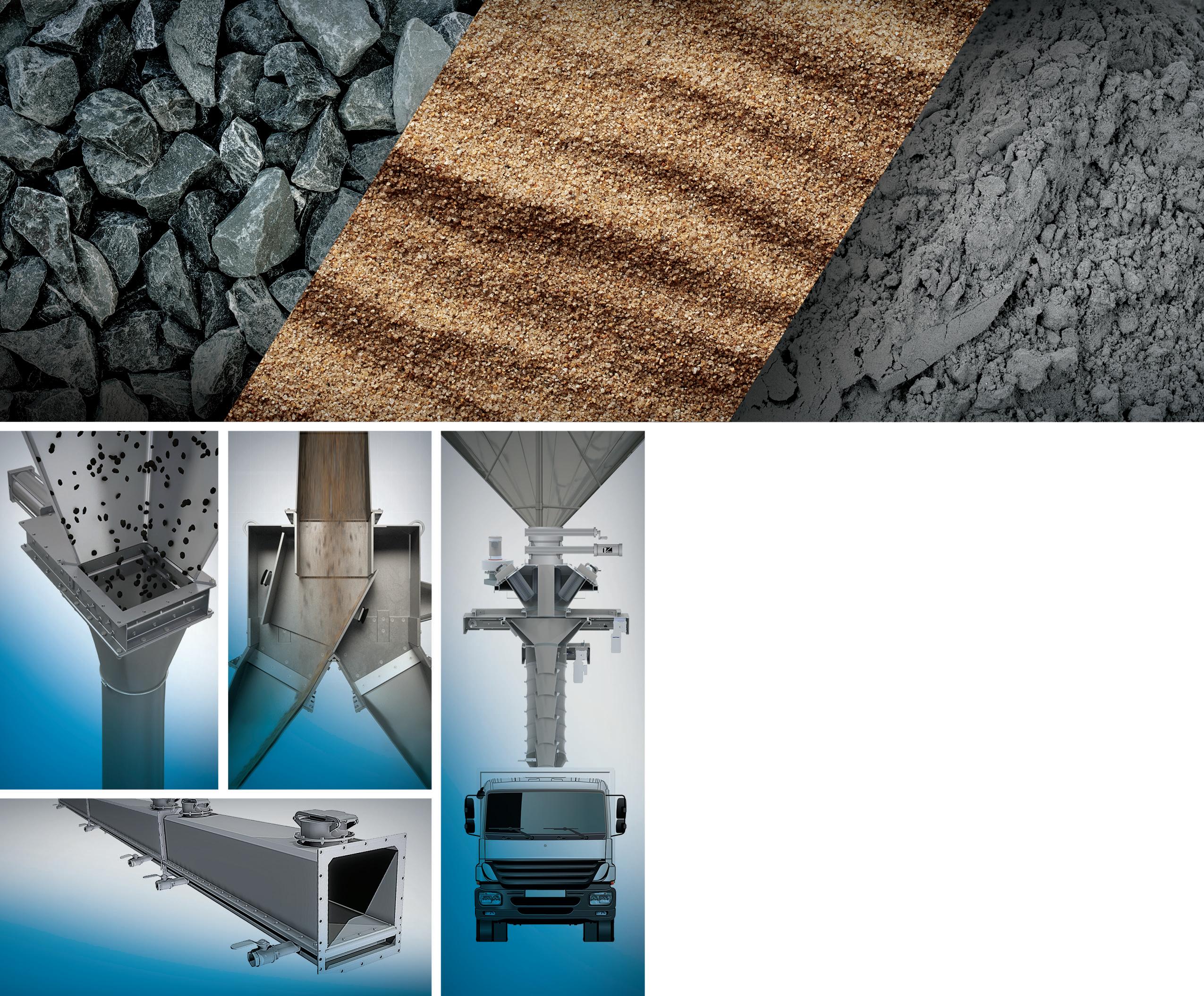
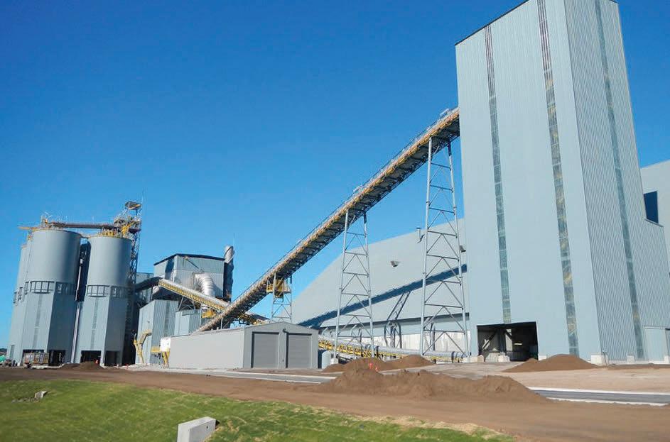
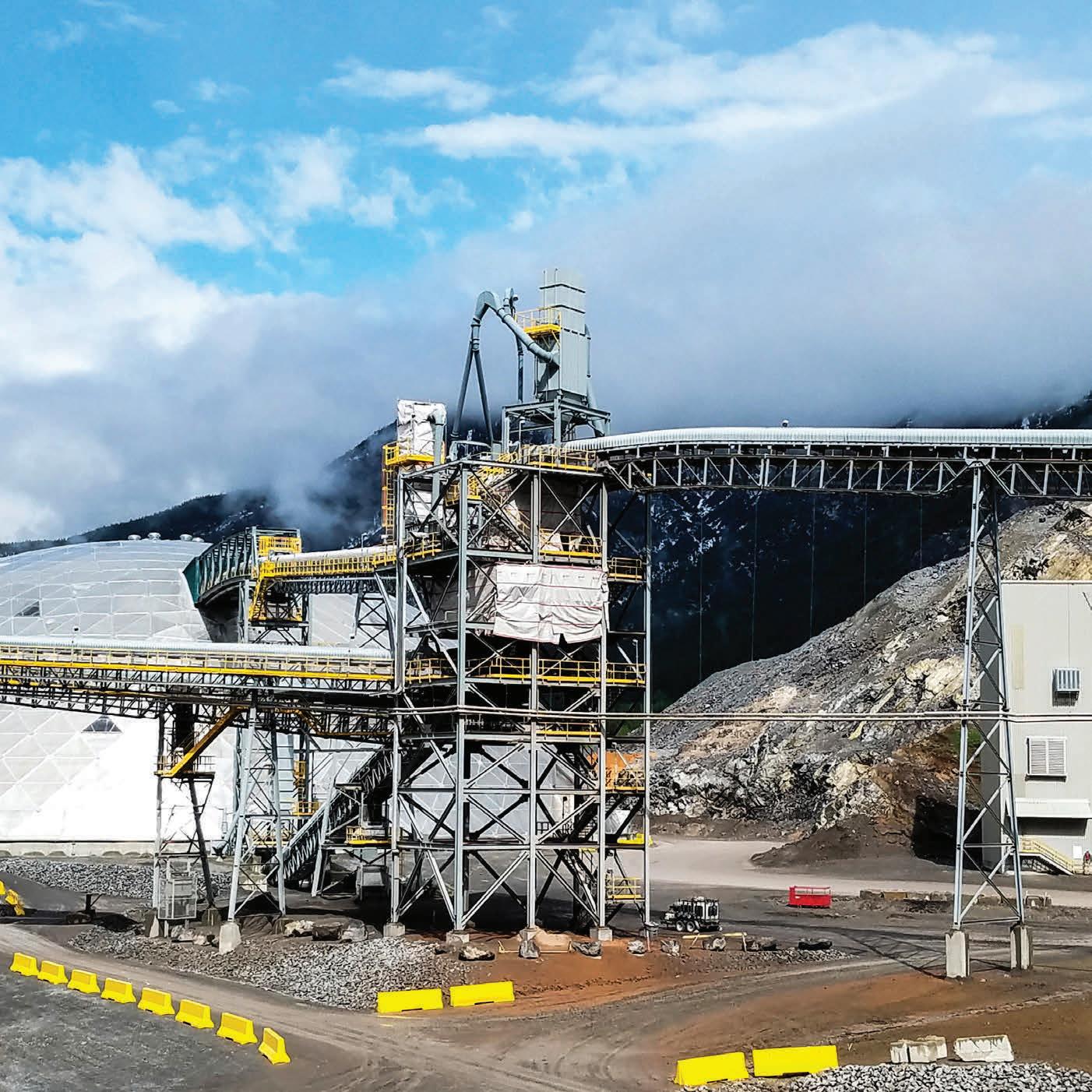

critical to performance, sorbent particle size dictates material handling properties and removal efficiencies in electrostatic precipitators and baghouse filters. Empirical data from the field, as well as laboratory flow testing, have demonstrated that larger median particle diameters (i.e. D50) are recommended for optimum handling.2,6 Specifically, a 32% improvement in flow properties was demonstrated between particles with D50 = 2 μm and particles D50 = 11 μm.7,8 This is likely due to small particle sized hydrated lime sorbents being more cohesive than larger particle, and small particles can facilitate pluggage in the conveying system.7 Additionally, fine particle sized hydrated lime can become irreversibly lodged in baghouse filter bags and bin vents (i.e. ‘blinding’), and can result in premature wear and poor bag cleaning efficiencies. Users should refer to their manufacturers’ design information regarding particle size and carefully weigh
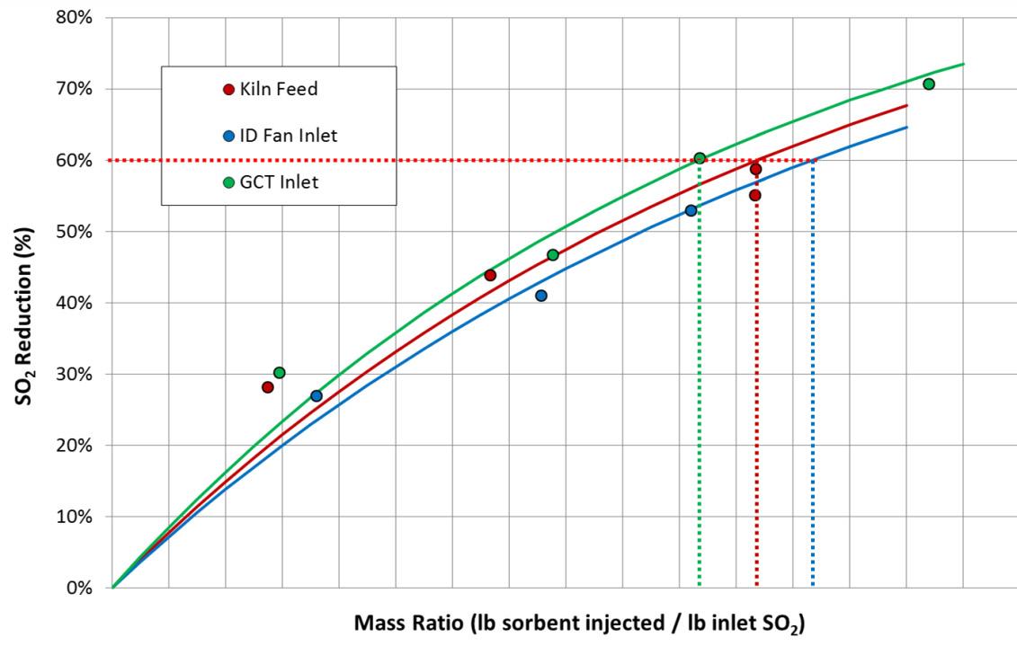
Figure 6. Comparison of DSI performance as a function of injection location. Sorbacal was injected at three locations: (1) with kiln feed, (2) at the gas cooling tower inlet, and (3) at the ID fan inlet. Note: these results do not always translate from plant to plant. It is critical to evaluate different injection locations at each plant to find the optimal injection location.
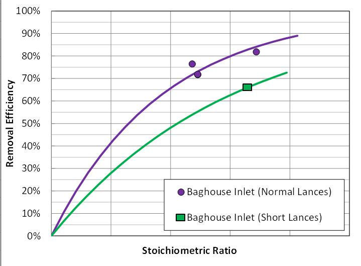
Figure 7. DSI performance with different injection lance configurations. CFD modelling is a useful tool to guide lance configuration and design to maximise efficiency and cost-effectiveness.
the impacts of introducing particles outside of the design range. Likewise, electrostatic precipitator particulate capture efficiencies decrease below approximately 6 μm and can result in increased particulate emissions.7,8
The key parameters to consider when choosing sorbents are pore volume, surface area, and median particle size (D50). Pore volume and surface area are the most critical performance drivers for acid gas capture. Particle size dictates material handling properties and removal efficiencies in electrostatic precipitators and baghouse filters. Larger median particle sizes (≥ 6 μm) have been found to offer the best handling and particle capture results.7,8 It is noteworthy that ‘available Ca(OH)2’ impacts acid gas removal performance to a much lesser extent than surface area, and pore volume since sorbent utilisation rates (i.e. fraction of calcium ions consumed in the reaction) are seldom in excess of 30% .
Enhanced hydrated lime sorbents provide the following benefits over standard hydrated lime, thanks to their engineered and improved physical properties designed to enhance acid gas reactivity:
f Operating cost savings – EHLS typically reduce sorbent usage by 30 – 50% over standard hydrated lime sorbents, which results in a lower annual spend on sorbent.
f Less impact on electrostatic precipitator baghouse filter – lower sorbent dosage rates will result in less dust loading to particulate capture equipment. Less dust to an electrostatic precipitator may directly impact particulate collection efficiency and, for a baghouse filter, this could impact bag cleaning cycle frequency. Particle sizes play a critical role in electrostatic precipitator /baghouse filter operational efficiencies. Respective equipment manufacturers should be consulted on particle size guidelines.
f Fuel and raw material flexibility – if a lower cost fuel or raw material becomes available but results in increased acid gas emissions, then an EHLS can provide additional flexibility since it has the ability to achieve higher acid gas removal efficiencies than standard hydrated limes, without having to modify the existing DSI system.
f Increased storage silo capacity – lower sorbent consumption using EHLS results in more days of available storage in a fixed silo volume. Hence, reducing sorbent consumption by 50% equates to doubling the silo storage capacity.
f One DSI system for acid gas and Hg control – EHLS blended with PAC are available and preclude the need for two separate systems.


Process


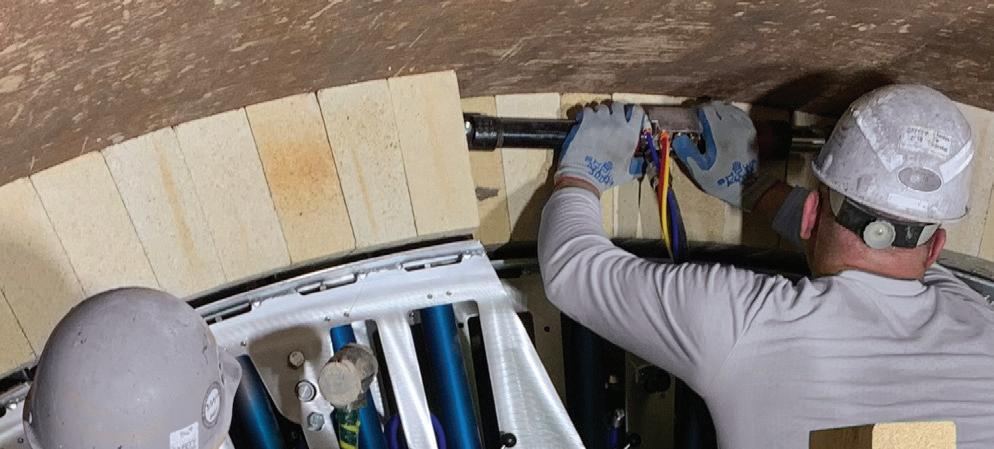


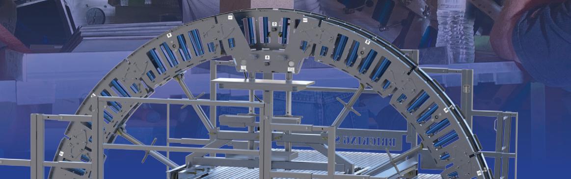

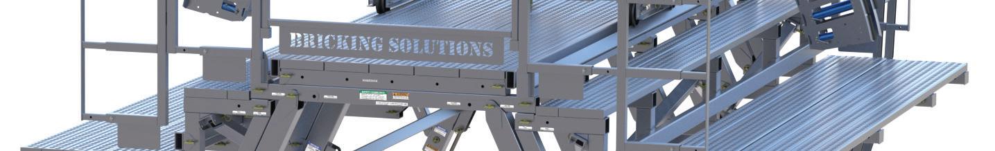
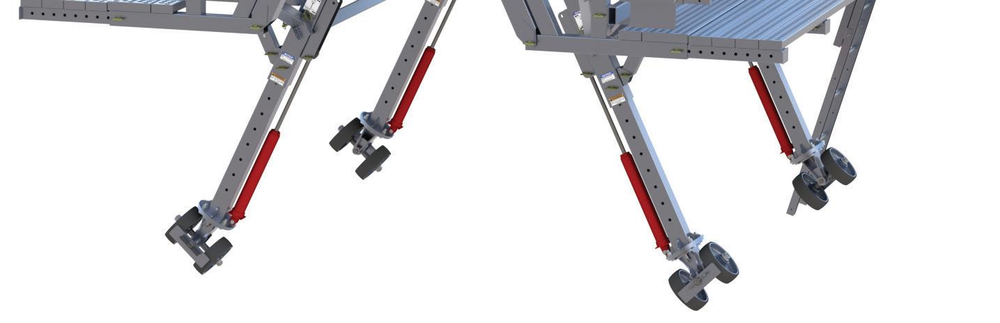

The two most critical components to implementing a successful compliance strategy are proper sorbent selection and sorbent distribution in the gas stream. Assuming that the DSI system is properly designed, installed, and operated,2,6 choosing the most effective sorbent, injection location, and injection grid design are the next critical steps to optimising system cost-effectiveness. Although ELHS are typically more costly than standard sorbents on a delivered basis (i.e. US$/t), higher sorbent efficiencies often result in overall lower total cost of ownership. For example, an EHLS may cost 30% more than a standard hydrated lime; however, EHLS usage rates are often 30 – 50% lower than the standard hydrated lime, resulting in a net cost savings. Figure 3 illustrates relative SO2 capture performance of a standard hydrated lime sorbent and an EHLS at an industrial facility.
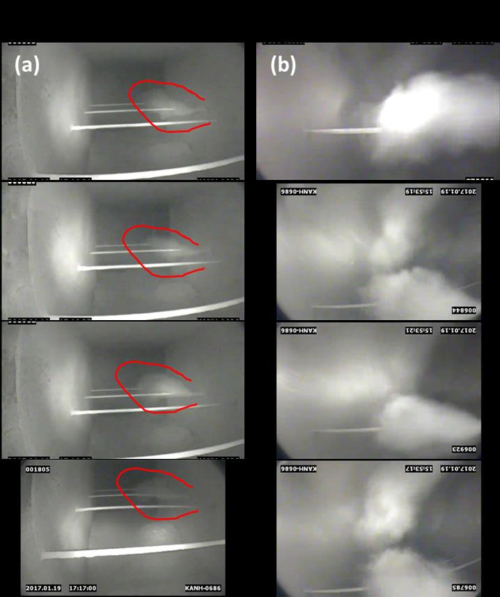
Figure 8. View of sorbent dispersion in process gas stream. In-duct camera images of sorbent distribution at a cement plant. Images were recorded upstream of the injection lance(s), which were located between an electrostatic precipitator and baghouse. (a) Illustrates the poor-sorbent distribution with the original single-lance configuration. The area in red highlights the white sorbent plume. (b) Illustrates the improved sorbent distribution with the addition of lance (for a total of six). Additionally, flow was balanced by modulating dampers at the baghouse clean air plenum. Originally, flow in this duct was highly stratified (as verified with Pitot tube measurements), and flow balancing and addition of lances resulted in a cloud of sorbent distributed across the duct.
Requesting proposals from sorbent suppliers
Care should be taken when preparing sorbent requests for proposals, since the quality specification outlined in the request for proposal could inadvertantly result in selection of an unsuitable or single source supplier. Identify potential sorbent suppliers and communicate with them to better understand the most critical sorbent attributes, as well as the chemical and physical properties of the sorbents they offer. For example, not understanding that sorbent purity (i.e. ‘available Ca(OH)2’) is less critical than surface area, pore volume, and that large particles are superior to smaller particles, may result in choosing a single supplier, which may not be the most cost-effective choice.
Sorbents blended with PAC
For simultaneous Hg and acid gas abatement, Lhoist’s Sorbacal acid gas sorbents can be blended with PAC. Simulateneous capture of mercury and acid gases offers the advantage of requiring only one feed system to install and operate. For applications in which mercury control is either intermittent (i.e. when using certain raw materials) or only needed for low injection rates, a blended product can be advantageous. Lhoist’s blended product enables concurrent acid gas and Hg control using a single sorbent injection system (versus installing and maintain two nearly identical pieces of equipment) and injects the sorbents simultaneously as a pre-blended homogeneous product.
Injection location and lance configuration
Another critical aspect of the DSI process is choosing the best injection location and specific design of the injection grid. The injection location and grid design directly impact how the sorbent is introduced into the gas stream. Sorbent distribution and coverage in the gas stream dictate pollutant removal efficiencies and resultant operating costs. A key question is where to locate the injector(s). The target pollutant(s) typically guide where to locate injection lances; however, it is recommended that each facility perform site-specific testing, especially for cement applications. It is recommended that several injection locations are evaluated during a trial, with a temporary DSI system. For example, SO2 capture by hydrated lime is typically favoured with injection at higher temperature; whereas, HCl capture tends to be favoured at cooler temperatures. Figure 6 illustrates relative SO2 abatement performance in a cement plant, with injection at kiln feed, gas cooling tower inlet, and ID fan inlet. Figure 7 illustrates the impact of lance design on sorbent performance. Without a trial to determine the best injection location, incorrect injector location selection can result in higher usage rates and annual costs.
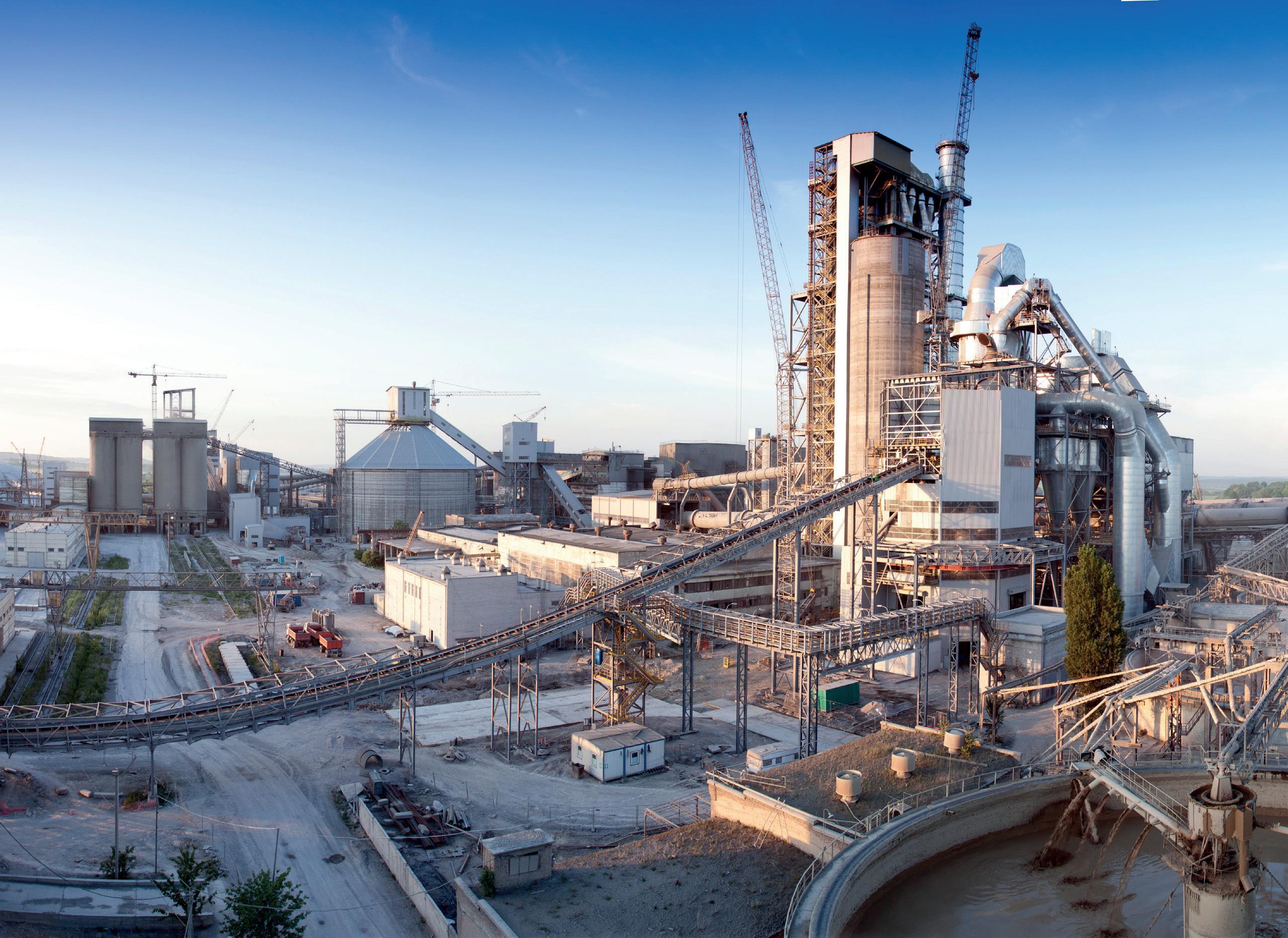
• International cement news
• Regional reports
• Market analysis
• Event previews and reviews
• In-depth technical articles
• In-depth regional analysis by key players in the industry
• Comprehensive technical reviews on all aspects of cement production, from the quarry face to despatch

Once injection location is determined, injection grid design is the next key performance driver. Injection grid designs can be as simple as a single injection lance, or as complicated as a multi-lance design with various penetration depths. Over the past few years, new injection technologies have emerged, significantly improving sorbent distribution within the gas stream, and reducing sorbent consumption. These systems can result in operating cost savings with a relatively quick return on investment. CFD modelling is a valuable tool for guiding injection grid design to optimise sorbent distribution. In-duct cameras can also be used to visually inspect sorbent distribution after system installation, helping to confirm good distribution and identify inefficiencies. Figure 8 is a photograph taken with an in-duct camera inserted into the gas stream to assess sorbent dispersion during a full-scale DSI field trial.
Sorbent selection, proper location of injectors, and injector grid/lance design are the most critical parameters that determine overall DSI system efficiency. Over the past two decades, EHLS’ have been specifically optimised for acid gas abatement applications. In the past, sorbent selection was driven by geologically-dictated hydrated lime purity (i.e. available Ca(OH)2). Today, sorbent purity has little impact on performance and sorbent performance is primarily driven by porosity (i.e. surface area and pore volume). Additionally, blended sorbents (PAC and EHLS in one sorbent) can reduce the system cost (i.e. only one injection system is needed). EHLS particle sizes have been optimised for superior material handling and particulate capture by baghouse filters and/or precipitators (i.e. larger particles are better). Locating injectors in a cement plant should be driven by data from trials with temporary DSI systems. Once injectors are located to maximise sorbent efficiency, injection grid design should be guided by CFD modelling. Following system installation, in-duct cameras can be used to evaluate and tune sorbent injection grids to ensure excellent distribution and coverage. Many of these critical parameters are easily evaluated during a short product trial and can result in significant operating cost savings in the long run.
References
1. CIRO, W., & SEWELL, M., 'HCl Control for MACT Compliance' WorldCement, April 2014 pp. 50 – 53; SEWELL, M., & HUNT, G., 'Optimizing Dry Sorbent Injection Technology', WorldCement, April 2015.
2. FILIPPELLI, G., 'Living with Your DSI System', CIBO Boiler Operations, Maintenance & Performance Conference, May 2016.
3. FOO, R., DICKERMAN, J., HUNT, J., JOHNSON, L., & HEISZWOLF, J., 'ESP Compatible Calcium Sorbent for SO2
Capture at Great River Energy’s Stanton Station' MEGA Symposium Conference Proceedings, August 2016.
4. HEISZWOLF, J., SEWELL, M., & HUNT, G., 'Enhanced Hydrated Lime – A Simple Solution for Acid Gas Compliance', IEEE-IAS/PCA, May 2017.
5. 'Dry Sorbent Injection for Acid Gas Control: Process Chemistry, Waste Disposal and Plant Operational Impacts', Institute of Clean Air Companies, July 2016.
6. WOLF, D., 'Results of Hydrated Lime DSI Field Trial Tests for HCl Removal from Industrial Coal Fired Boilers', CIBO Industrial Emissions Control Technology XII Conference, August 2014.
7. ZHIBIN, Z., & GUOQUAN, Z., 'Investigations of the Collection Efficiency of an Electrostatic Precipitator with Turbulent Effects', AerosolSci.Technol.1994, 20 (2), 169 – 176.
8. LIN, G. Y, CHEN, T. M., TSAI, C. J., 'A Modified Deutsch-Anderson Equation for Predicting the Nanoparticle Collection Efficiency of Electrostatic Precipitators', AerosolAirQual.Res.2012, 12 (5), 697 – 706.
About the authors
Dr. Ian Saratovsky is Director of Lhoist North America’s Flue Gas Treatment group. Ian holds a PhD in Inorganic Chemistry and Environmental Engineering from Northwestern University, an MBA from Northwestern University’s Kellogg School of Management, and was a Fellow at Oxford University in the UK for several years before entering the air pollution control industry. Since then, Ian has 17 years of experience in air pollution control, water treatment, and industrial process optimisation. Much of Ian’s work has focused on developing and deploying new products for acid gas abatement and efficiency improvements in industrial processes.
Gerald Hunt earned Bachelors and Masters Degrees in Chemical Engineering from the State University of New York at Buffalo. Gerald is currently a Senior Manager of Flue Gas Treatment Applications with Lhoist North America, Fort Worth, TX. Gerald's 17 years of experience in the air pollution control industry include performing field trials, proposal management, as well as process engineering in dry sorbent injection, dry scrubbing, and wet flue gas desulfurisation technologies for the utility and industrial sectors.
Travis Reynolds is Manager, Flue Gas Treatment Applications, with Lhoist North America. Travis began his career in air pollution control in 2006. Travis worked as a plant operator at a local utility in East Tennessee for 9 years while attending college, followed by 18 years with Alstom/GE Power, working on all aspects of semi-wet and dry flue gas desulfurisation. In 2023, Travis joined Lhoist North America. This change allowed Travis to get back to the roots of what he enjoyed the most during his career, such as building relationships and helping customers solve air emissions challenges.
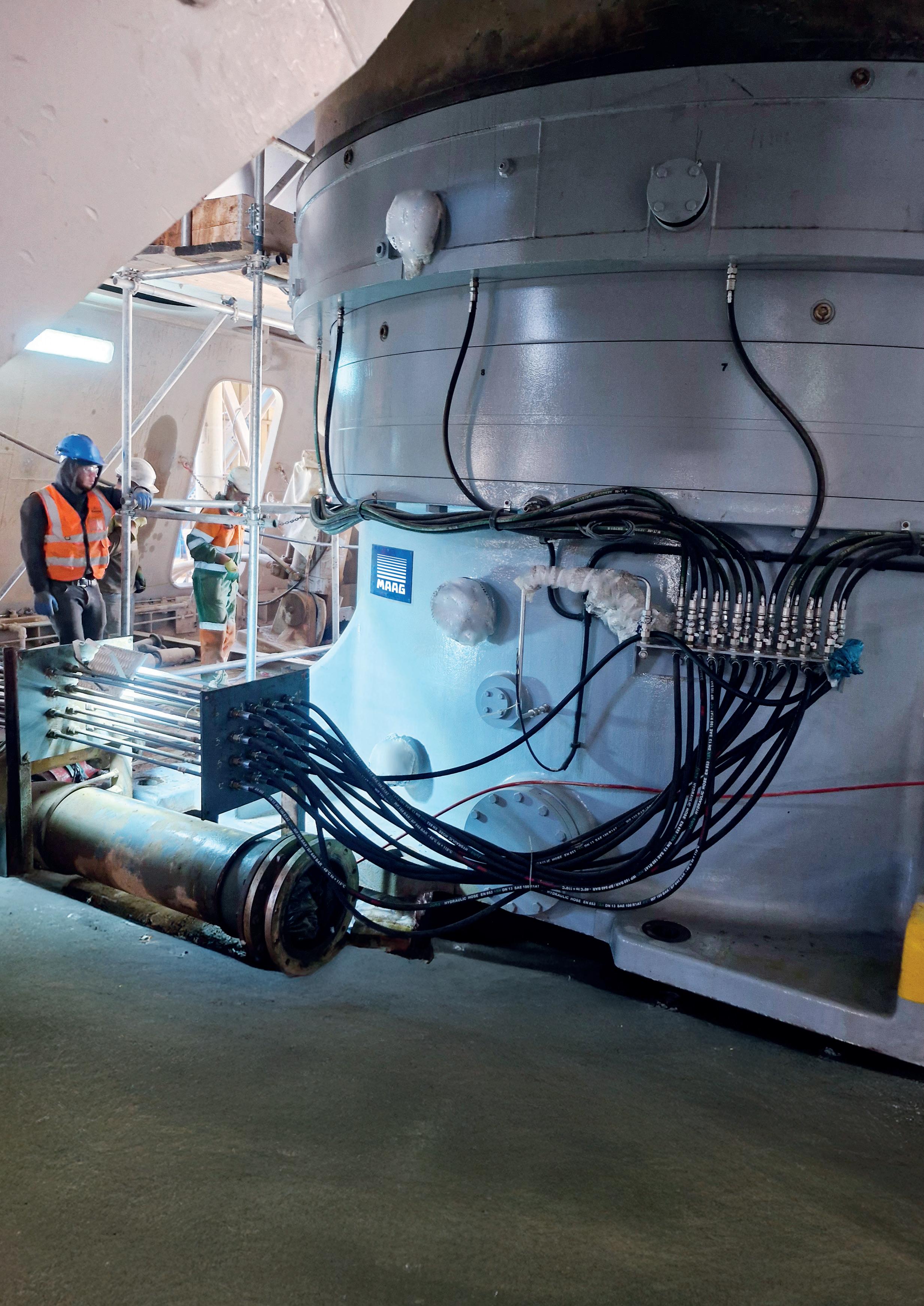
Mohamed Rezk, MAAG Gear Middle East and Sub-Sahara Africa, highlights a gearbox replacement project in Iraq that increased production and reduced energy consumption.
Maintenance and replacement of large gear units in cement plants is a major task that requires thorough planning, technical coordination, and cost-efficient arrangements, with a focus on minimising downtime.
MAAG prioritises client needs through maintained open communication channels and prompt responses to operational challenges. Collaborative efforts between MAAG’s sales and engineering teams ensure durable, competitive solutions tailored to client requirements. This article highlights a recent successful gear unit replacement project undertaken by MAAG for a cement producer in Iraq.
A cement plant in Iraq – one of the region’s largest, with high production capacity to meet market demands – faced significant constraints due to an outdated gearbox. The plant’s technical team sought
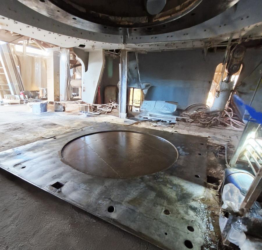
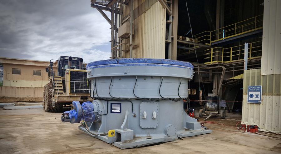
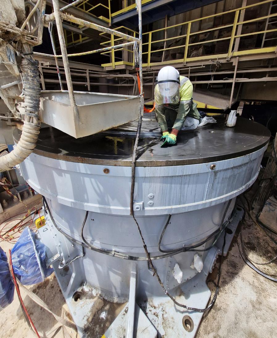
alternative solutions, engaging MAAG’s regional sales team to identify optimal replacement options.
As a leading cement producer, the client demanded high standards for performance, technical specifications, safety factors, durability, and engineering quality. Emphasis was also placed on post-installation communication and support from the gear supplier’s aftermarket services.
Following detailed technical discussions and studies, the IronDrive-4350/A was selected for replacement, renowned for exceptional durability among vertical roller mill (VRM) gear units. Cost-effectiveness was ensured by reusing existing components: oil units, piping, output couplings, auxiliary drives, and foundations. The client approved the solution, and the order was finalised.
MAAG started fabrication and adhered to the agreed delivery timeline. Throughout the production period, regular updates and manufacturing-step approvals were provided. A successful test run was conducted under client supervision at MAAG’s workshop in Poland. Timely shipment followed, supported by seamless coordination and documentation between MAAG and the Iraqi client.
Mr. Witold Malecki, a seasoned MAAG gear expert with over 30 years of extensive experience in the field, supervised the gearbox replacement project. His vast knowledge and expertise were instrumental in ensuring the smooth execution of the installation. The entire process was meticulously planned and executed, resulting in the successful completion of the installation within an impressive time frame of just 15 days.
Once the new MAAG gear was installed, the mill resumed operations seamlessly. The results were impressive: the feed rate increased by an average of 17 tph, significantly enhancing the plant’s productivity.
Additionally, the specific energy consumption (SEEC) was reduced by 1.37 kW/t, reflecting a substantial improvement in energy efficiency. These improvements boosted productivity, cut energy costs, and aligned with the client’s sustainability objectives by reducing the plant’s overall energy footprint.
Per contractual obligations and MAAG maintenance protocols, a specialist conducted checks after 1000 operational hours, assessing oil parameters, vibration, temperature, displacement, alignment,
and foundation fixation. All parameters indicated stable performance. Ongoing support is provided by MAAG’s sales and aftermarket teams to address client needs.
MAAG Engineering selects the right design from their wide product range based on specific applications, parameters, and site condition. For this project, the 2-stage MAAG Iron Drive was chosen as the most beneficial and reliable solution.
The MAAG Iron Drive series accommodates power ranges from 1500 up to 13 000 kW – all in a compact unit. The 2-stage variant features antifriction bearings on bevel and planetary stages (sleeve bearings available on request), while the 3-stage unit uses sleeve bearings throughout. Its circular casing ensures optimal force distribution and flow from mill table to the foundation of the vertical roller mill. The robust gear casing for the MAAG Iron Drive can be executed as fabricated and welded construction or in cast steel.
To absorb the shock loads generated by the grinding process, the axial thrust bearing that supports the mill table is composed of a dozen single tilting thrust pads, all of which are lined with Babbitt metal at the contact surface. Each pad is lubricated individually by a forced oil circuit. Subject to specific grinding process requirements, the MAAG Iron Drive incorporates a high-pressure lubrication system for hydrostatic table support and is equipped with emergency shoulders to safeguard gears during table tilting.
The MAAG Iron Drive benefits from smart design, optimising mill performance and enabling proactive maintenance.
f Easy access to bevel gearing: achieved via a larger inspection port.
f Reduced downtime: facilitated during adjustment of bevel gear contact patterns.
f Simplified maintenance: the bevel pinion can be removed without dismantling the gear unit from the mill.
f Open communication: clear and consistent communication channels ensure prompt resolution of challenges or concerns.
f Collaborative approach: close coordination between sales, engineering teams, and clients delivers durable, competitive solutions tailored to specific needs.
f Technical excellence: technical proficiency and safety are prioritised, ensuring adherence to high standards of performance and reliability.
f Cost-effectiveness: reuse of existing components, where feasible, guarantees quality without compromising cost efficiency.
f Timely delivery: agreed fabrication and delivery timelines are rigorously followed, with continuous client updates.
f Post-installation support: ongoing maintenance checks and guidance ensure long-term operational success.
f Condition monitoring services: advanced monitoring tools enable proactive maintenance planning and prevention of unplanned downtime.
MAAG takes pride in supporting clients to overcome critical bottlenecks, enhancing production efficiency while minimising downtime. Performance improvements, reduced energy consumption, and streamlined operations underscore these achievements.
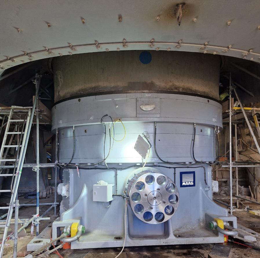
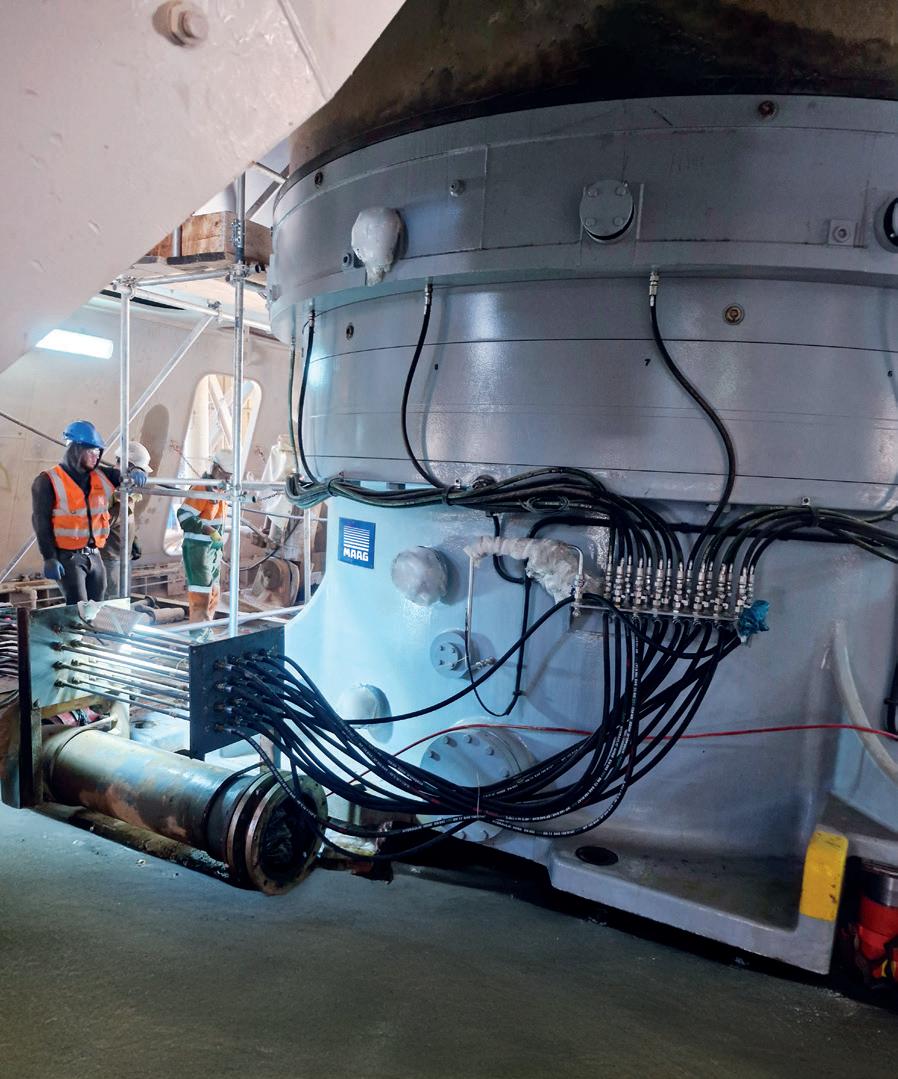


Andy Turner, SEW-EURODRIVE UK, discusses the benefits of using predictive maintenance software to reduce downtime in the cement industry.
In the often fast-paced and incredibly demanding environment of cement plants, any downtime experienced in operations can be agonising, causing costly and lengthy maintenance breaks, as well as lost revenue.
As one of the most complex manufacturing sectors in the world, the cement industry is characterised by continuous and high-volume production, involving the crushing, grinding, mixing, and blending of raw materials including limestone, clay, and marl.
Unexpected failures or shutdowns of the equipment used can impact the entire manufacturing operation, with significant consequences for the manufacturers, who face the challenge of organising last minute maintenance jobs at an often high cost.
According to The Cement Institute, maintenance within the cement industry is one of the highest contributors to the overall production cost, representing between 15% and 25% of the total manufacturing expenditure.1
This is a huge outlay for companies to face, especially when placed alongside rising supply and production costs, more tariffs and import taxes, and higher wages.
Despite these high costs, ensuring continuous operations is crucial to meeting production goals, and companies have to explore every avenue to minimise downtime, maximise machinery life, and maintain efficiency.
One way of doing this is through predictive maintenance, a proven strategy which helps firms to maintain the key equipment within their production line, by monitoring system

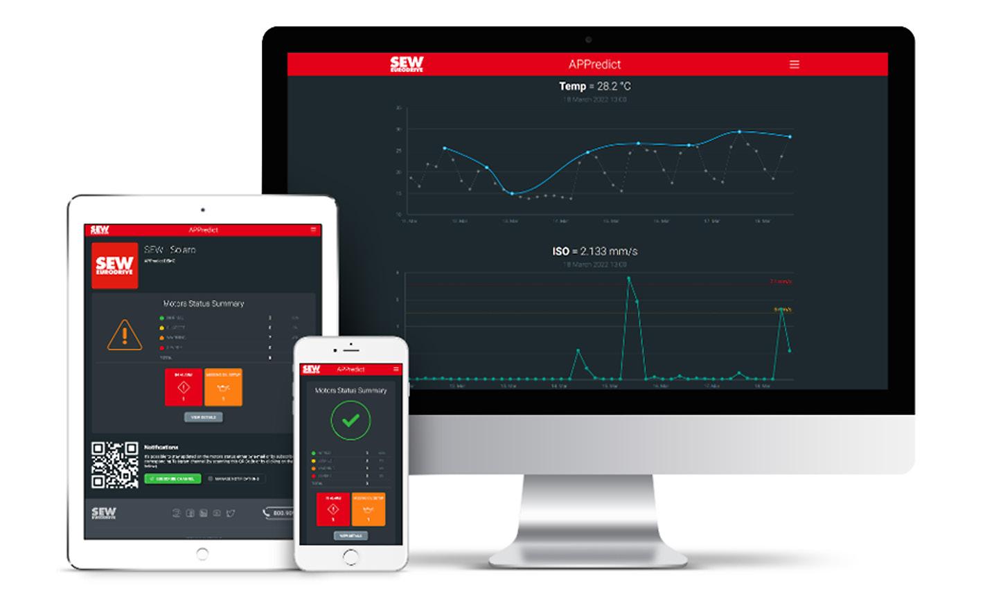
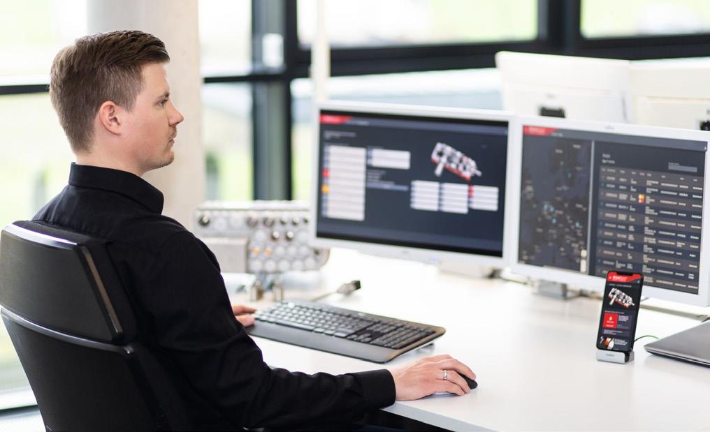
operations and flagging potential issues before they turn into something disruptive.
Predictive maintenance can be thought of almost like repairing a chip in a windscreen before it becomes a crack – except it involves preparing for maintenance well before any issues even arise.
Predictive maintenance software helps businesses to avoid unexpected machinery failures, reducing the potentially costly repairs, and maximising the amount of time a production line can stay running without downtime.
As the software is ‘predictive’ it means repairs can be scheduled in advance, using a data-driven approach that analyses the condition of equipment used to provide meaningful insights into system performance and expected issues.
SEW-EURODRIVE is well versed with how much difficulty downtime can cause for every industry involved in production, with the cement sector and other heavy-duty industries facing particular struggles due to the manufactured materials potentially accelerating wear on machinery.
This experience has led SEW-EURODRIVE to develop predictive maintenance software applications to help monitor the system statuses of both internal production lines and clients' production lines.
The first of these software applications to be developed was DriveRadar®, an IoT (internet of things) suite used to support everything from the installation and start-up of systems involved with production to maintenance and fault diagnostics.
Like with other predictive maintenance software available, this application uses sensors installed within gear units to record physical parameters relevant to operation, as part of a process known as condition monitoring. The data acquired includes operating hours, input speed, direction of rotation, vibration behaviour of rolling bearings and gearing, oil level, temperature, and viscosity, electronics temperature, and finally, ambient temperature.
This raw data is continuously collected, analysed, and interpreted, offering vibration analysis, a forecast of remaining service life for rolling bears and gearing, forecasts of oil levels, and predictions of when oil changes will be needed.
A key component of condition monitoring and predictive maintenance, vibration analysis is a powerful tool for monitoring
rotating machinery and covers the condition of individual bearings and their components, as well as individual gearings.
As part of this, vibration sensors measure the frequencies of vibration within machines or equipment, in an effort to detect abnormalities that may indicate an issue. The vibration analysis then studies the oscillatory motions of machines and their components around an established equilibrium point, identifying potential problems including misalignments, defects, and loose parts.
The analysis covers factors including amplitude (the magnitude of the vibration, measured in displacement, velocity, or acceleration), frequency (the number of oscillations per unit of time), and phase (the relative position of one vibrating component with respect to another over time).
These factors are then used to identify specific machine faults and their severity. The phase analysis identifies issues including looseness and imbalance, whilst the amplitude determines how big the problem is.
Various vibration thresholds can be set based on industry standards and equipment manufacturer recommendations, which will trigger alarm or notification to operators once hit. For example, for manufacturers looking to meet ISO compliance standards, they can look to set maximum thresholds based on the ISO 10816-3 vibration severity chart.
Through measuring, analysing, and interpreting these machine vibrations, engineers and operators can better access and understand the health and performance of key production line equipment. This allows them to identify issues immediately and implement repairs or replacements before problems snowball into something bigger.
Alongside monitoring the vibrations of equipment, predictive maintenance helps to estimate the expected service life of existing machine components.
Remaining useful life (RUL) is the length of time a machine will operate before it requires repair or replacement. The probability of machinery failure is measured by looking at lifetime data, run-to-failure (RTF) histories, and threshold values.
Using lifetime data to estimate RUL involves analysing historical data about machinery performance, to predict how long it will continue to function before it needs to be repaired. This works alongside RTF histories, which looks at how long parts have lasted before repair previously, and threshold values, which form part of the aforementioned vibration monitoring.


Together, this data helps to increase the longevity of machinery through greater predictability of potential issues, whilst also improving safety for employees operating the equipment, as it reduces the risk of accidents happening due to machinery failure.
Predictive maintenance also includes the monitoring of oil life and levels. Oil condition monitoring (OCM) involves the measuring and analysis of changes in the oils and lubricants present within machinery, tracking potential contamination, alongside the degradation in oil quality from new to old.
Oil aging sensors determine when it is time to change the oil, so that equipment can continue to run efficiently, whilst also lasting longer. Alongside this, sensors check miniscule changes in oil condition, which can indicate problems in machinery, such as equipment wear.
Oil monitoring helps to save on resources, as it ensures oil is only replaced when needed, and it also reduces maintenance costs when used as part of a full proactive maintenance strategy, allowing operators to fix issues before machinery is damaged.
Overall, when utilised alongside both vibration analysis and expected service life predictions, oil monitoring helps to build a complete predictive maintenance strategy that will keep cement production lines continuously operational and keep customers happy.
With the world continuing to shift towards digitisation, predictive maintenance software has had to extend its capabilities, moving beyond the plant floor and straight into the hands of engineers and operators, at any time, any place.
Like other companies, SEW-EURODRIVE have looked for ways to allow customers instant access to important data on machinery conditions. This has led to SEW-EURODRIVE developing their latest software, APPredict, which has all the vital components of predictive monitoring software, with the added benefit of being able to view data from a phone app.
Bringing this predictive maintenance software into the hands of engineers allows for issues to be flagged in an instant, with warning notifications sent by email. In industries as complex as cement production, the ability for operators to see equipment data wherever they are helps with process efficiency, allowing maintenance to be scheduled whether they are onsite or off site.
Overall, predictive maintenance offers peace of mind, with operators of cement production lines safe in the knowledge that their expensive, highly specialised machinery can stay running for long periods of time without worrying about downtime.
When relying on a reactive 'fix-it-when-it-fails' approach, unnecessary replacements and avoidable repairs often lead to wasted resources, while also potentially frustrating customers and stakeholders due to an unreliable production line.
In a heavy-duty industry like cement manufacturing, this equipment is even more expensive to repair and replace, meaning reactive maintenance eats into profits when things go wrong.
Implementing predictive maintenance software offers a simple solution that can significantly reduce costs in the long run, minimising risks while ensuring the manufacturing process maintains the expected production levels and efficiency.
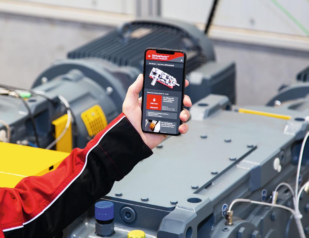
The additional upfront investment more than pays off over time, stopping pesky maintenance jobs from increasing production costs, and avoiding potential lost revenue.
All production industries have evolved enormously over the past few years, and cement manufacturing is no different. Securing a positive future for the sector relies on the adoption of new technologies, all designed to make life easier, and predictive maintenance can play a key role in this.
References
1. 'The Cement Institute' – https:// thecementinstitute.com/maintenance-in-thecement-industry Drive radar being used on the factory floor.
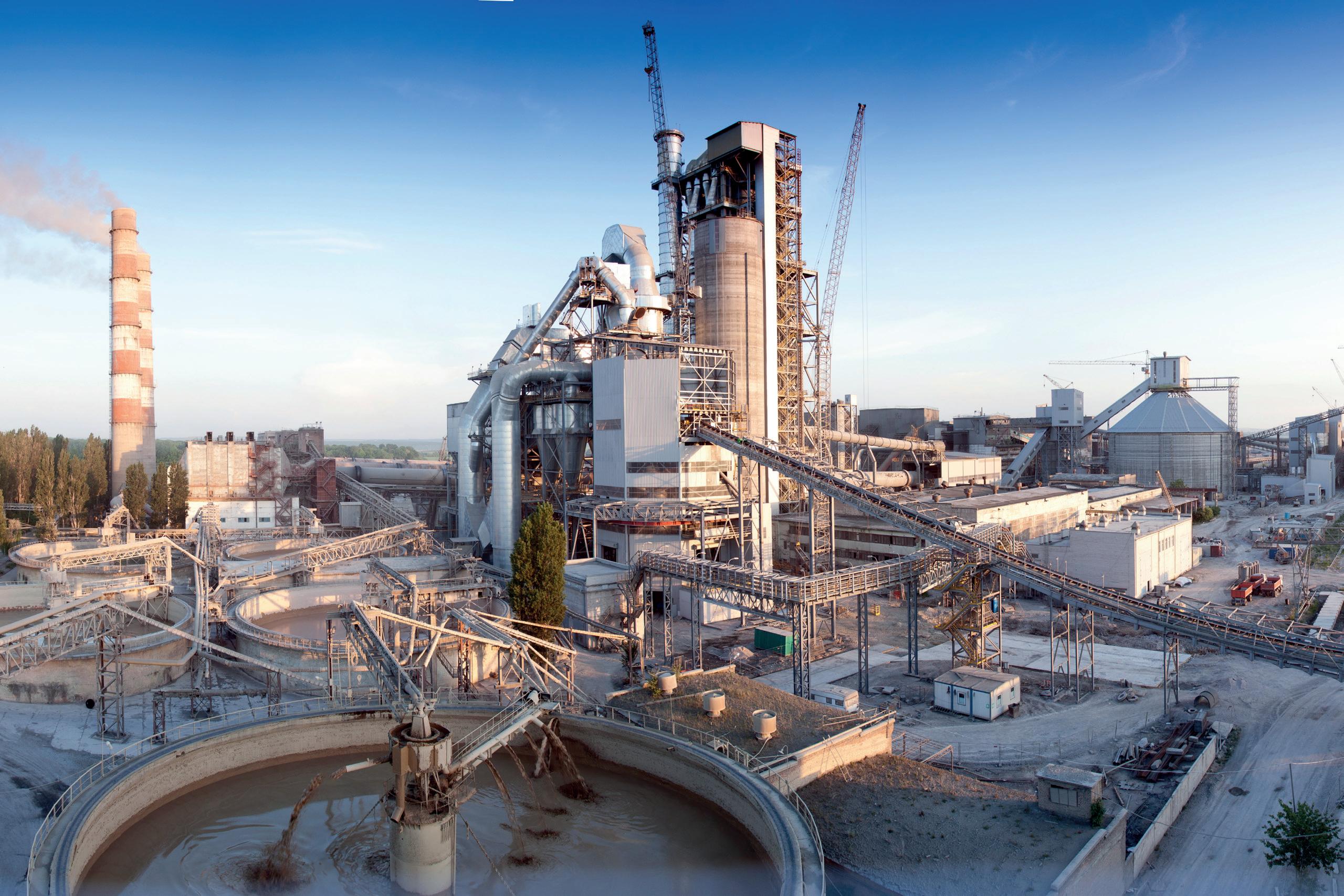
www.worldcement.com/subscribe
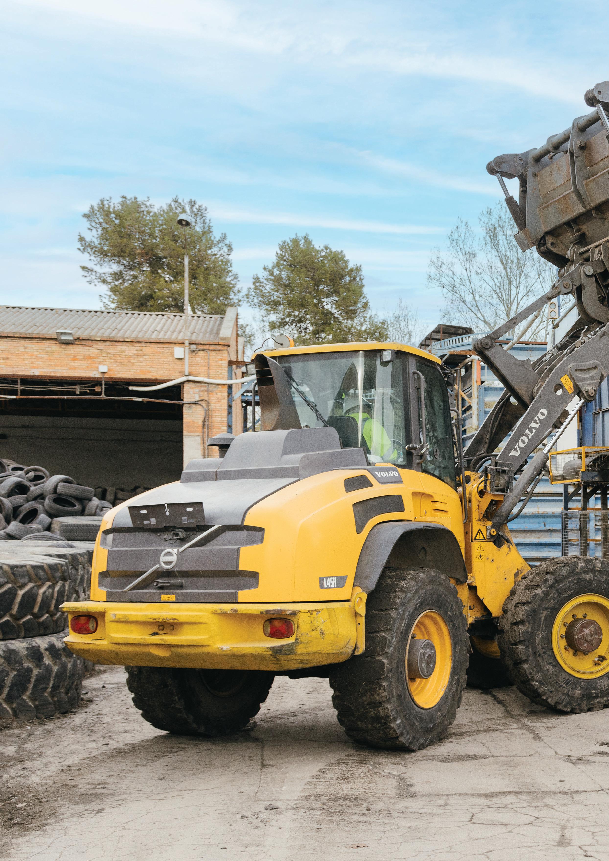

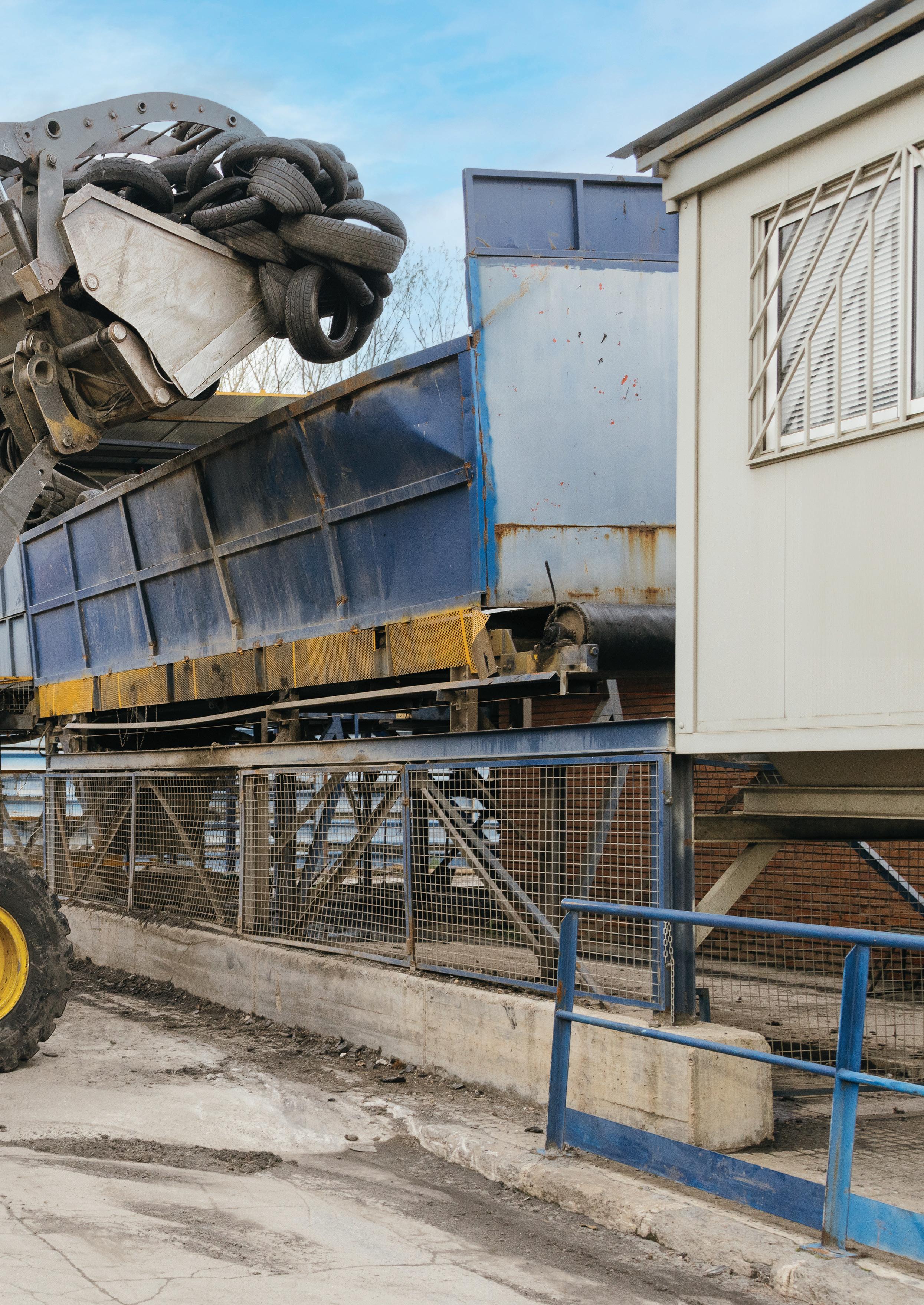
Molins demonstrates how an end-of-life tyre recycling project is advancing decarbonisation efforts in the cement industry.
From playground surfaces to soccer fields, and even urban furniture like bike lane dividers, a common material is appearing across urban landscapes: recycled rubber from end-of-life tyres (ELT). Spain generates an estimated 300 000 t of ELTs each year, making recycling and repurposing projects essential for advancing towards circular economy and protecting the environment.
The ELT recycling project led by Molins at its GRP (granulated rubber project) plant in Manresa, Barcelona, represents a milestone in building a robust and sustainable circular economy. Since its establishment in 2016, this initiative has stood as
an example of innovation and sustainability, providing real solutions to address environmental challenges and fostering more responsible industrial practices.
Equipped with the most advanced rubber crushing and screening technology, the GRP plant in Manresa operates two production lines that carry out a series of high-tech industrial processes, including primary and secondary crushing, magnetic separation, aspiration separation, particle size classification, and bagging into large bags for distribution. The process begins with primary crushing to produce shredded ELTs.This shredded material is then transferred to the secondary section, where it undergoes further size reduction in the secondary mill, and textile fibre and steel are separated. After this, the rubber granules are classified by particle size, bagged, and stored. Two distinct lines are prepared for the plant’s final products based on their end-use. Chips destined for energy recovery are transported in bulk to Molins' cement factory, using containers and mobile floor trucks. These chips, a granulated rubber from ELTs, are tailored to a specific particle size – carefully determined through research to maximise combustion performance and energy efficiency in the cement factory’s kiln.
With these high-tech facilities, Molins has processed over 17 million tyres in the last eight years. This achievement has been made
possible by the plant’s five-step process, which includes primary shredding, initial screening, secondary milling, secondary screening, and the final separation of components. Each step produces essential materials, such as shredded rubber, granulated rubber of various sizes, steel, fibre, and chips.
The use of ELTs as alternative fuel (AF) plays a crucial role in the decarbonisation efforts of Molins' operations. At the Sant Vicenç dels Horts (Barcelona) plant, 55% of the fuel used comes from alternative sources, including ELT, significantly reducing dependence on fossil fuels and lowering the carbon footprint of Molins’ solutions.
Meanwhile, rubber granules destined for material valorisation are sorted by particle size according to customer needs, bagged, and dispatched via curtain-sided trucks. The granulated rubber finds a second life in diverse applications, including playground surfaces, sports tracks, and other industrial products.
Molins’ ELTs recycling project not only keeps waste out of landfills but also supports a circular economy model by transforming tyres into reusable resources. Energy and material recovery at the GRP plant aims to minimise natural resource consumption, reduce greenhouse gas emissions, and lessen landfill dependency.
Additionally, the plant’s energy-efficient design and location near the Sant Vicenç dels Horts factory significantly reduces transportation costs and environmental impact, further underlining Molins’ dedication to a sustainable industry.
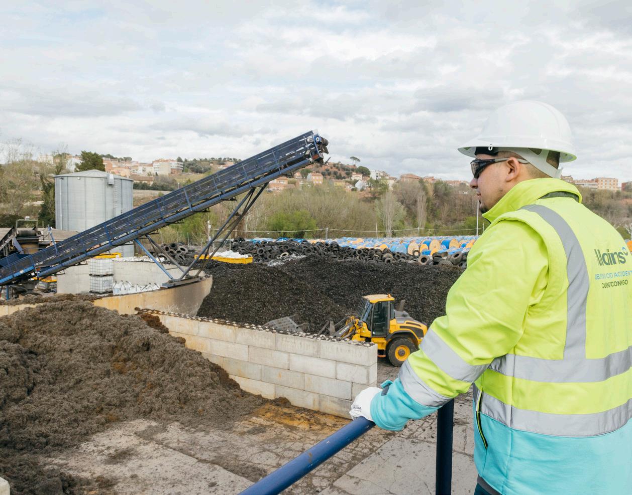
The project represents more than a corporate success story; it is part of Molins' broader strategy to advance sustainability across the construction industry. Molins' vision goes beyond recycling tyres and aims to integrate recycled materials into all its production processes and final products.
One of the Molins’ main projects is the establishment of an alternative raw materials plant, located in Barcelona. This facility, launched in 2022, is dedicated to processing demolition and other industrial

waste, giving a second life to materials that would otherwise end up in a landfill by transforming them into high-quality, sustainable products. By the end of 2024, the plant had reached the significant milestone of recovering more than 193 000 t of construction, demolition, and other industrial waste since its inauguration. In 2024 alone, it recovered over 93 500 t of materials, representing a 25% increase compared to the previous year.
Repurposing alternative raw materials has become a core component of Molins’ commitment to circularity and decarbonisation in the sector. The plant prevents the direct emission of over 2000 t of CO2 per year, equivalent to the emissions of more than 750 cars. Furthermore, the plant’s proximity to the Sant Vicenç dels Horts cement factory substantially reduces transportation costs, and the environmental impact associated with raw material transport.
Both the alternative raw materials plant and Molins’ tyre recycling project at the GRP plant stand as examples of innovation and commitment to sustainability, demonstrating the vital role of industry in fostering a circular, resilient economy. By confronting environmental challenges with determination and vision, Molins is setting the path for a more sustainable future. These projects exemplify not only a practical transformation of waste into resources but also a critical shift in

how industrial development is conceived and approached in the 21st century.
Molins launched a new corporate identity in May 2024, aiming to position itself as a global leader in innovative and sustainable construction solutions. Under the new Molins brand, the organisation unifies its various commercial brands in Spain, including Cementos Molins Industrial, Promsa, Propamsa, Pretersa-Prenavisa, and Precon. Molins’ slogan 'building the present, shaping the future' emphasises its commitment to sustainability and innovation.
Molins has introduced six new business areas: cement, concrete and aggregates, circular economy, construction solutions, precast solutions, and urban landscape. Additionally, it launched Susterra, a new range of products that recognises and distinguishes solutions with sustainable attributes, reflecting its integrated business model focused on circularity, decarbonisation, and social well-being. Susterra includes everything from low-carbon footprint cement, mortar, and concrete, to urban furniture solutions and circular economy initiatives.
The new visual identity was implemented across all Molins businesses last May, with Escofet and Calucem retaining their names but incorporating the new identity into their logos.


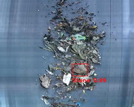
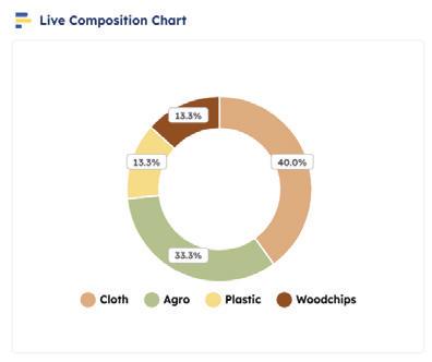
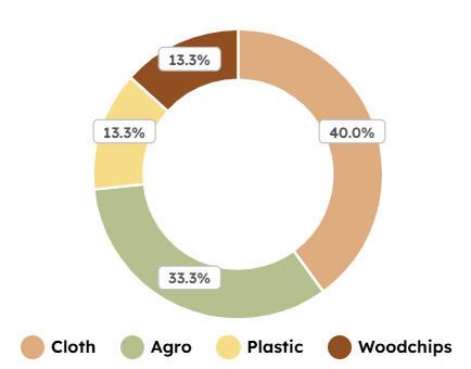


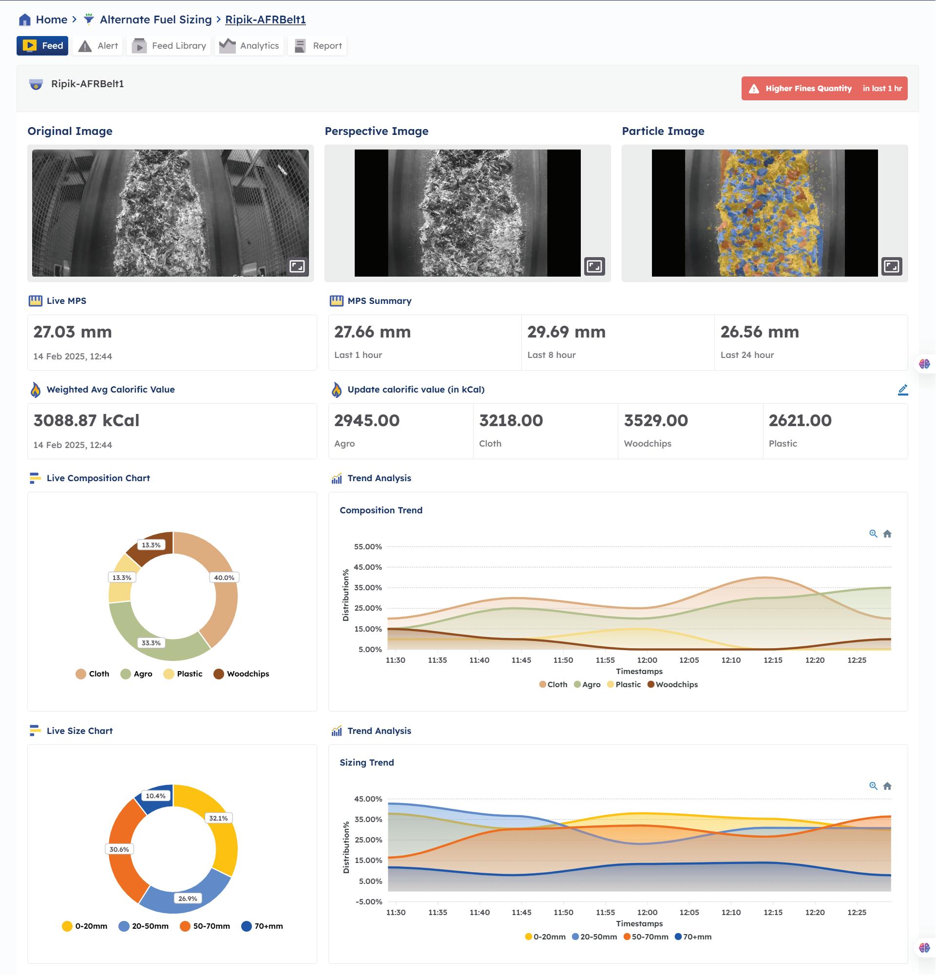
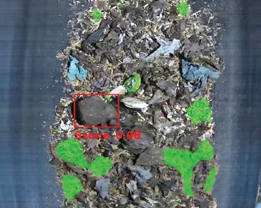

Ighnatios Maatouk, ES Processing, explains how AI and machine learning are driving the digital transformation of cement manufacturing processes.
The cement industry is at a crossroads of transformation, driven by digital advancements, net zero roadmaps, and the need for operational efficiency. As one of the most resource-intensive industries, cement manufacturing has historically struggled with sustainability, fluctuating operational costs, and maintaining product quality. However, the integration of artificial intelligence (AI) and machine learning (ML) promises to address these challenges by digitalising the processes that have traditionally relied on human intervention and conventional methods.
Digitalisation in the cement industry: the need for change
Cement manufacturing is a complex process, involving several stages – grinding raw materials, clinkerisation, and cement grinding. Each stage requires precision to ensure product quality and energy efficiency. Historically, plant operators have relied on manual adjustments, periodic laboratory testing, and experience to optimise production. However, this approach has its limitations, including process time delays, inconsistencies in product quality, and higher energy consumption. In response to the growing pressures of reducing carbon emissions, minimising energy costs, and ensuring consistent product quality, digitalisation has emerged as the path forward for the industry.

Digitalisation enables cement manufacturers to use real-time data, automation, and advanced analytics to make informed decisions. ES Processing’s optimiser systems are specifically designed to integrate AI and ML into cement plants, providing a fully digitalised and automated solution that not only enhances operational efficiency but also transforms cement manufacturing into a proactive, autopiloted process.
Autopilots: the gain for cement manufacturing
One of the most significant contributions of ES Processing to the cement industry is its suite of autopilot solutions: cement mill optimiser (CMO), vertical mill optimiser (VMO), and kiln process optimiser (KPO). These solutions leverage AI, ML, and APC to optimise key stages of cement production.
f The CMO, initially developed for ball mills, utilises AI/APC to continuously predict cement fineness (Blaine and residue) every 30 seconds, making real-time adjustments to process parameters.
f The VMO, developed for vertical mills, follows a similar approach but is designed to optimise the more complex dynamics of vertical mills.
f The KPO ensures that the kiln, one of the most complex, critical, and energy-intensive components in cement production, operates with optimal efficiency and stability.
These systems represent a new era of digitalisation in cement manufacturing, enabling real-time process control and optimisation. Rather than relying on
intermittent sampling and manual adjustments, the CMO, VMO, and KPO autopilot the cement production process with continuous monitoring and precise adjustments, ensuring consistent product quality and enhanced efficiency.
How autopilots improve digitalisation in cement manufacturing
Real-time monitoring and precise adjustments. One of the most significant advantages of ES Processing’s AI-APC solutions is the ability to shift from manual, reactive operations to automated, proactive processes. Traditionally, cement plant operators would take quality samples every hour, and any necessary process adjustments would be made based on these results.
However, this process was time-consuming, and the lag between sampling and adjustments often led to inconsistent product quality and inefficiencies.
With ES Processing’s digital systems, product quality is accurately predicted every 30 seconds. AI-driven soft sensors continuously monitor and predict key process parameters, such as cement Blaine and residue for mills, as well clinker C3S and free lime for kilns, allowing the system to anticipate variations and make adjustments before product quality deviates from desired levels. This real-time data analysis and adjustment capability has dramatically reduced dead time, eliminated human error, and improved process stability.
The digital nature of the systems also ensures that multiple variables are controlled simultaneously, enabling the plant to optimise operational conditions continuously. By acting every 30 seconds, the system maintains a highly stable process, which is critical in achieving
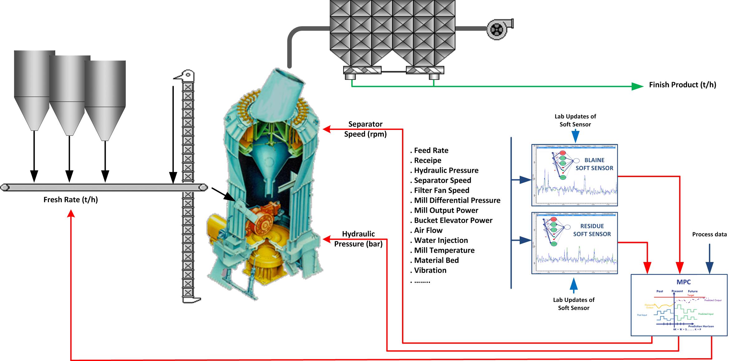
consistent clinker reactivity, cement fineness, and ultimately, higher-quality output.
ES Processing’s solutions are built around advanced AI and ML algorithms that learn from historical plant data. The soft sensors – a core feature of the CMO, VMO, and KPO systems – are trained using past operational and quality data. This allows them to predict cement quality metrics in real time without needing laboratory samples. This approach eliminates delays caused by manual testing and ensures that production remains uninterrupted, with accurate quality predictions driving the decision-making process.
Another key technology of these systems is model predictive control (MPC), which optimises the manipulated variables of mills and kilns. MPC models are capable of handling complex plant dynamics, long-dead times, and multivariable interactions. They do not only predict future process behaviour but also optimise operational conditions to maintain stable product quality and minimise energy consumption.
The cement industry is a major contributor to global CO2 emissions, and reducing the carbon footprint of production processes is a top priority for manufacturers. ES Processing’s AI solutions contribute to energy efficiency by minimising unnecessary energy consumption during production. The autopilot systems optimise operational conditions to reduce specific energy consumption while maintaining output levels.
For example, by reducing the variability in clinker reactivity and cement fineness, the systems allow plants to operate at higher production rates with lower energy input. In some cases, cement plants using ES Processing’s autopilot solutions have seen a 12% reduction in energy usage. This reduction not only lowers operational costs but also contributes to environmental sustainability by reducing CO2 emissions.
ES Processing’s AI solutions have been successfully implemented in cement plants worldwide, delivering significant improvements in production efficiency, product quality, and energy consumption.
At the SECIL Sibline plant, ES Processing’s CMO and VMO solutions were introduced to optimise the cement grinding process. The results were impressive: production rates increased by over 10%, while energy consumption decreased by
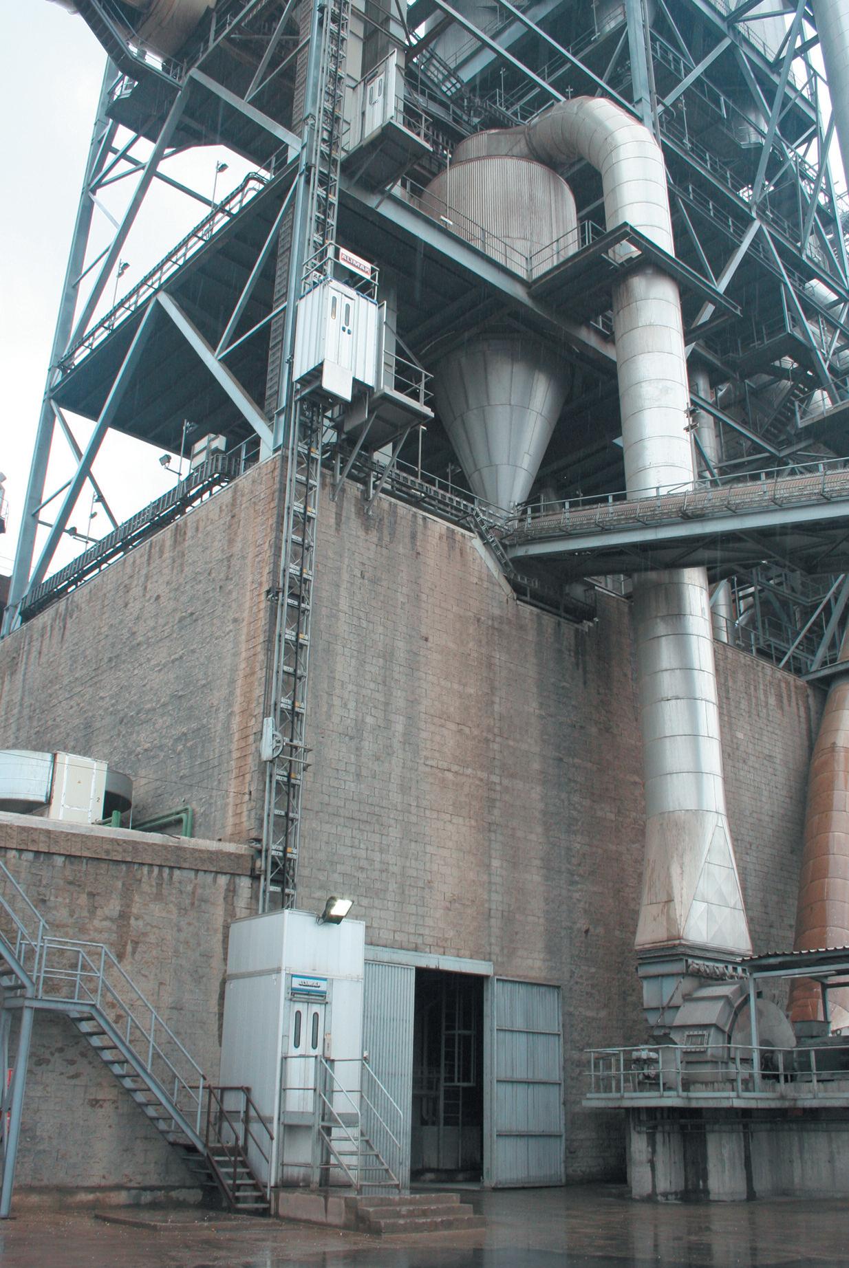
ARE YOU PAYING SKILLED STAFF TO CLIMB STAIRS OR TO PRODUCE CEMENT?
Cement plants all over the world rely on Alimak rack and pinion elevators to provide reliable, efficient vertical access for maintenance and inspection Designed to operate in demanding industrial environments, outdoors and indoors, Alimak elevator s require no expensi ve shafts or machine rooms, and they can easily be installed on new and existing structures Standard capacities range from 30 0 k g to 7,0 0 0 kg, with up to 24-ton capacity available upon request
Contact us at info@alimak com for further information
more than 12%. Moreover, the fineness standard deviation – a key indicator of cement quality consistency – was reduced by more than 50%, ensuring that SECIL could consistently produce high-quality cement with fewer fluctuations in product quality.
TITAN Cement Group adopted ES Processing’s AI/APC solutions to enhance its grinding operations in Sharccem. Similar to SECIL, TITAN saw a significant improvement in cement quality, with a reduction in variability and a more stable production process. The autopilot system allowed operators to focus on strategic tasks,
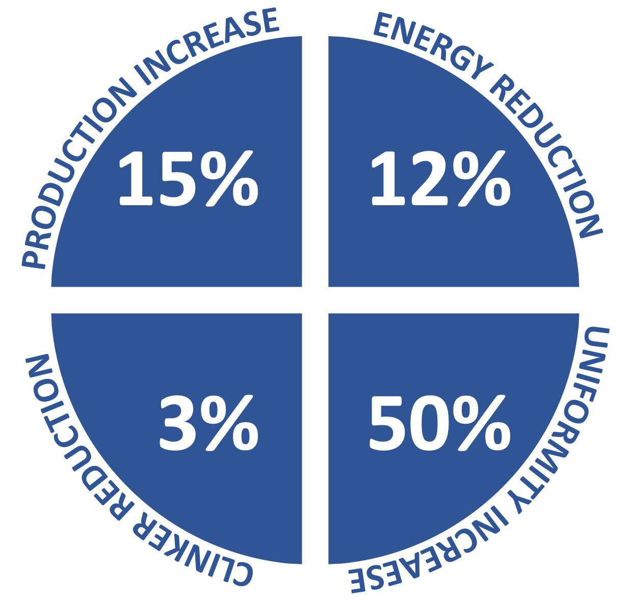
Approved gains for cement manufacturing.
while the AI-driven solutions handled day-to-day adjustments and optimisations.
This shift not only improved operational efficiency but also reduced the plant’s energy consumption.
The SAMAN cement implemented the CMO solution to optimise its cement mills operations. SAMAN benefited from the real-time control capabilities of the CMO system, which led to an increase in production volumes by more than 8%, all while lowering energy consumption.
As the cement industry continues to face challenges related to sustainability, efficiency, and product quality, the role of digitalisation will only become more critical.
ES Processing’s AI/APC optimiser solutions provide a blueprint for the future of cement manufacturing, where real-time data, automation, and advanced analytics drive continuous improvements in operational efficiency and sustainability.
By integrating autopilot systems such as the CMO, VMO, and KPO, cement plants can not only achieve higher production rates and lower energy costs but also ensure a more sustainable and profitable future. These types of solutions stand as a testament to the power of digitalisation in transforming one of the world’s most essential industries.
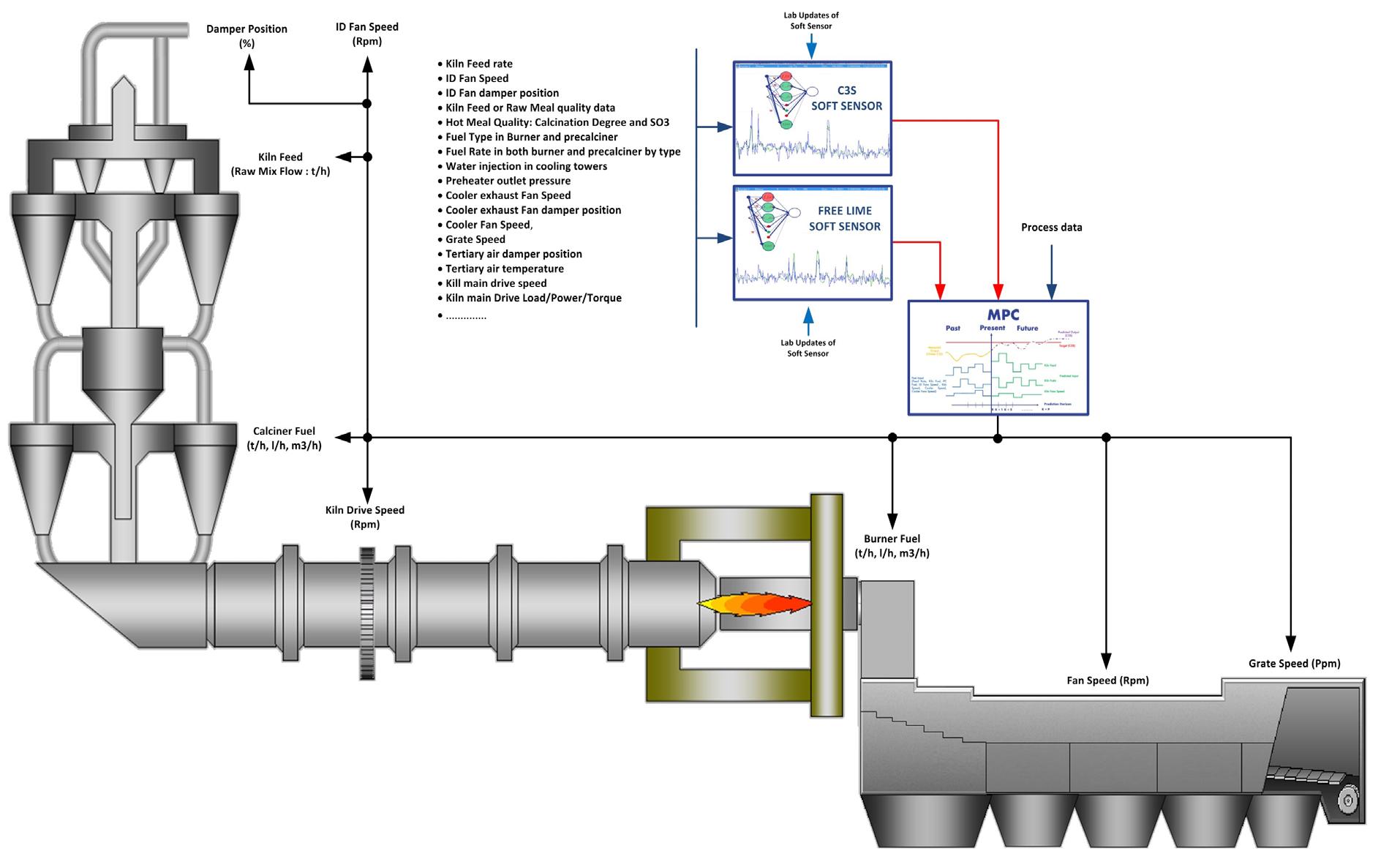


Ashutosh Dave, Schneider Electric, explores how digitalisation is key to tackling the challenges facing the cement industry, from improving competitiveness to addressing sustainability goals.
Heavy industries like cement production are facing increasing pressure to improve efficiency, sustainability, and competitiveness. Regulators, investors, peers, customers, and stakeholders are driving this pressure, and a growing gap exists between businesses already embracing these performance-enhancing digital solutions, and those that assume they still have time.
Many companies are already well off the starting blocks. According to McKinsey, an estimated 90% of organisations are currently undergoing some form of digital transformation. In 2024, spending on digital transformation is projected to reach US$2.5 trillion, and by 2027, global spending is expected to soar to US$3.9 trillion.
In other words, the competition is fierce. Digitalisation is no longer just an option; it is a strategic imperative. It drives safety and efficiency, benchmarks energy usage, reduces waste and emissions, and empowers plant workers to make efficiency suggestions for review by decision-makers and managers.
The consequences of inaction are clear, like the loss of clinker and cement production, operational inefficiencies, loss of improvement opportunities in real-time, and savings in overall energy consumption per ton of cement production. Beyond operational disadvantages, broader issues – such as climate change and energy transitions – require digitalisation. Failing to adapt means missing out on the opportunity to thrive in this new industrial landscape and drive meaningful change in the process.
The potential that industrial digitalisation enables is exciting because of what it enables: real-time decision-making, automation, improved quality and innovation across sectors, and more engaging roles for workers – allowing every individual to influence sustainable production methods.
Companies that have been slow to embed digital transformation programmes across their business risk being left behind by their peers and competitors, as they fail to tap into the potential that is on offer. Schneider Electric has embedded digital transformation programmes into 200 plants and research sites in 44 countries, and have a dedicated industrial digital transformation and consulting team to help businesses digitise operations. The reason for doing this on a global scale is that connectivity is vital to realising the true capabilities of software-defined automation and production.
The most recent 'Sustainability Lighthouse' factory, located in Hyderabad, India, has delivered remarkable results. Energy consumption has been reduced by 59%, CO2 emissions by 61%, water usage by 57%, and waste generation by 64%. These numbers highlight the power of combining digitalisation with sustainability and show tangible evidence of the advantages that can be achieved by capitalising on digitalisation at every level of the production process.
The progress achieved here is a result of utilising the capabilities of artificial intelligence (AI), big data analytics, cloud computing, internet of things (IoT), and smart devices. These technologies make it possible to achieve a digital workplace, enterprise online IT and benefit from insights on energy utilisation against production, emissions, and quality. At the heart of the IoT system architecture is the EcoStruxure platform. This connects everything on the shop floor to the top floor, collecting critical data from sensors to the cloud and analysing it to discover insights and act based on near real-time information.
As an example, the EcoStruxure Industrial Resource Advisor: Energy Management solution gathers, analyses, and visualises key energy data, empowering teams to enhance process and operational efficiency in a more immediate way. The module focuses on implementing short interval management (SIM), a hyper-focused element of waste energy recovery management. SIM involves structured progress checks every hour, ensuring swift responses to emerging process and operational issues. While effective, scaling SIM across crushing to packing operations can be challenging – but this is where these technologies excel for cement manufacturers.
Once implemented, EcoStruxure quickly proves its value to plant-floor workers. It simplifies data presentation, making operations more visible to everyone on the shop floor and all control room operations. When key performance indicators like energy production and quality lag, workers can suggest actionable solutions to resolve bottlenecks and enhance performance.
The platform also allows workers to flag issues, prompting supervisors to respond within a set timeframe. If unresolved, the system automatically escalates the alerts.
Most importantly, it has eliminated non-value-added tasks, allowing workers to focus on their core responsibilities and contribute more effectively. Systems like EcoStruxure showcase how digitalisation not only drives efficiency but also empowers people and supports sustainability.
Schneider Electric recently partnered with Omdia to conduct an in-depth analysis of the impact of digitalisation on job creation in heavy industrial companies. The report revealed that 45% of companies believe digitalisation will be pivotal in creating jobs on the shop floor, while 70% see it as a key factor in addressing talent shortages. Talent acquisition remains a major challenge, with more than half (52%) of
respondents reporting difficulties in attracting the right people.
The findings of this study show that digitalisation does not just benefit productivity and overall efficiency. It is vital for solving some of the people-centric challenges facing industrial businesses and sustainable operations as well. There is a real opportunity for industrial enterprises to optimise and enhance OT roles. By reducing the time spent on administrative tasks and enabling people to better fulfil their potential, many of the challenges these businesses face can be addressed, helping to build a sustainable future.
One of the most compelling findings of the report was that software-defined automation and digitisation are expected to attract new skills to the industrial sector. Within the next three years, respondents pointed to a growing need for expertise in robotics programming and integration. And yet, 49% of companies acknowledged having 'no' or 'insufficient' skills in these areas – nor in data processing, visualisation, or analytics.
A notable obstacle industrial companies face in their digital transformation is a workforce resistant to change. Workers fear the unknown, worry about job stability, or resist adopting new practices due to the extra work involved. In fact, 38% of surveyed companies identified organisational culture as a top three barrier to implementing digital solutions, noting that risk aversion can impede adoption.
The most effective way to address this challenge is to actively involve workers, and understand pain points in the digitalisation process. When employees are engaged and included, their buy-in often leads to measurable growth and the adaption of new technologies. Workers may initially experience uneasiness – or even cognitive bias – against new technologies, worrying that these innovations could introduce new problems or complicate legacy systems.
However, when employees feel their voices are heard, there is a greater likelihood of digitalisation being seen as a tool to enhance, rather than disrupt, work lives. This underscores a vital cultural element: successful technology adoption must be people-centric and inclusive. By addressing concerns and fostering collaboration, businesses can ensure that digitalisation empowers their workforce and drives meaningful transformation.
Finally, it is also important to understand that investment in digitalisation is critical for energy-intensive heavy industries like cement to address the challenges of sustainability. According to Copernicus, the European Union's
climate change service, it is now "virtually certain” that 2024 will be the warmest year on record. 2024 also marks the first year that global temperatures will exceed 1.5˚C above pre-industrial levels, breaching the goals outlined in the Paris Agreement.
Governments are stepping up to confront these challenges – albeit with some recent dilution of key policies in certain areas. Looking to the positives, the European Union has recently introduced the Corporate Sustainability Reporting Directive (CSRD), a transformative piece of legislation requiring companies to report on the environmental impact of their operations.
In much the same way that GDPR reshaped global privacy standards, CSRD is expected to have a significant global impact. It will encourage businesses to adopt practices that minimise their environmental footprint. This should result in boosting interest in initiatives such as the circular economy and renewable energy, driving job growth.
Indeed, a recent study conducted by Schneider Electric in partnership with Boston University for global sustainability, found that adopting clean, green, and renewable energy technologies in could create more than 2 million jobs and generate up to 141 million additional job years in Europe and the US alone. This innovation shows that digitalisation not only enhances productivity but also reduces fuel waste and enables companies to spend their resources more wisely.
Furthermore, there are many groundbreaking technologies like this that have not been mentioned, such as energy modelling with data analytics combining power and process, AI for operation & safety and simulation changes through digital twin technology. By creating virtual models of dynamic process, chemical reactions, machine operations, heavy industry manufacturers can now build, test, and optimise designs before physical production or operational changes in near real-time. There is a whole world of opportunity in connecting real and virtual worlds that cannot be overstated, presenting vast opportunities for growth and innovation.
Ultimately, a transformation is taking place in the global energy sector – one that is both driven and supported by end-to-end energy digitalisation, from sourcing and generation to consumption. By building a connected intelligence network enriched with AI, industrial businesses can make better decisions, adapt to evolving conditions, and continuously improve in areas such as weather change impacts, energy tariff optimisation, energy generation, and curtailment scheduling for optimal energy usage.


thyssenkrupp Polysius reveals why prioritising proven equipment and adaptive workflows is key to rapid plant ramp-up and sustained profitability.
Every successful cement plant is built on a foundation of trust, reliability, and long-term performance.
thyssenkrupp Polysius understands the complexities of adding new capacity, as well as upgrading existing plants, and the challenges of constructing and supporting plants that meet the highest operational standards and customer needs. The success of these projects relies on the teamwork and expertise of the individuals
driving them forward, with engineering excellence playing a role as crucial as the equipment itself.
thyssenkrupp Polysius’ Grey Build approach is centred around highly qualified teams and proven, reliable equipment. This combination aims to build strong and long-term partnerships that support profitability from day one.
thyssenkrupp Polysius deliver field-tested equipment and a partnership that extends far beyond commissioning. The goals are:
f To ensure the plant ramps up quickly.
f To enable teams to operate safely and profitably.
f To ensure the equipment remains a reliable asset for years to come.
How can these goals be guaranteed? The answer is more straightforward than one might think. Olivier Terver, CEO of thyssenkrupp Polysius North America, explains: “Grey Build refers to executing large projects based solely on equipment that has already been successfully deployed in the past, as well as execution practices that have been proven to work. By mitigating the technological risk, thyssenkrupp Polysius improve its customers’ profitability and accelerate project timelines. Simply put, it’s about using what we know works so our customers can hit the ground running.”
For decades, thyssenkrupp Polysius has installed a large portfolio of equipment designed for a wide range of operational and design parameters. It is time to leverage that know-how even further.
By clearly understanding the factors that made a design successful in the past, it is possible to
establish guidelines that will shape the technical configuration, replicating those positive results and optimising performance.
This approach represents a fundamental shift from past practices. The focus is no longer on standardising layouts and implementing new equipment designs, but on promoting best practices and customer experience.
Some may ask, ‘is this just copying what has already been done?’ – The short answer is: no.
The Grey Build concept does not simply copy the equipment; it adapts relevant solutions to specific plant needs. While the foundation of Grey Build is based on existing equipment, it is not a simple replication of past projects. Each project is unique. Every cement plant operates under specific conditions – elevation, temperature, chemistry, and existing infrastructure all play significant roles in determining the best project configuration.
"We don't just copy equipment," says Olivier Terver. "We share our past experiences with our customers to collaborate towards the most relevant decisions for the project. Switching our OEM focus on the end results rather than the technology, we can adapt the set-up to meet the specific needs of each project, while maintaining the configuration that made the equipment operation successful. The operational performance of our equipment is largely independent of layout specifics, which is not the case for the operational teams of our customers. Our goal is to lay out workplaces that will support our customers' operations more than just our equipment footprint."
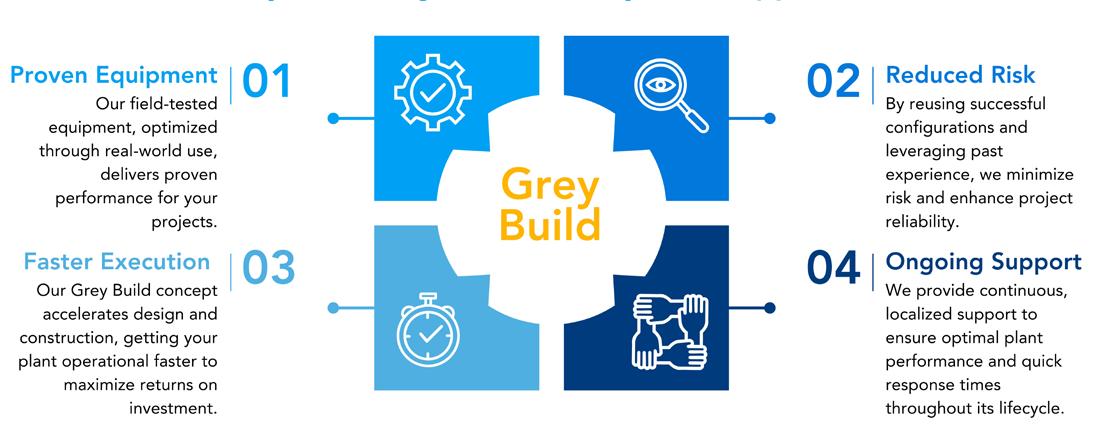
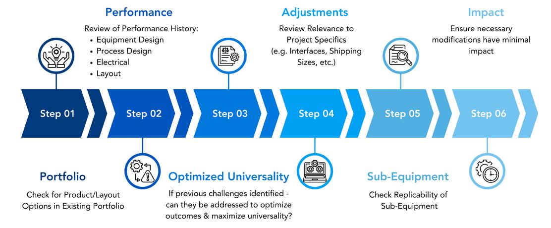
To maximise the benefits of the Grey Build approach, a systematic process is followed that prioritises equipment relevance and universality while allowing for site-specific adjustments when necessary (Figure 2). This is not a one-size-fits-all template, but rather a tailored solution that is expected to work for both parties.
Every project presents unique challenges, from processing different materials to integrating various material and gas handling systems. External factors like plant traffic, existing infrastructure, and future space planning often require flexible configurations for the main process equipment. Each Grey Build project will be aligned with the unique demands of the location.
Relying on thyssenkrupp Polysius’ experience with previous installations, more focused discussions can be held with customers, finding the most relevant product selection to meet their end goals. Equipment is prioritised based on it's performance and ability to meet specific goals, rather than simply offering the latest or most advanced technology.
Although projects may be influenced by previous work, every execution is unique. Engineering timelines and contract execution schedules remain the backbone of any project, and it is crucial that they align seamlessly for the overall success of the project.
With the Grey Build approach, the focus is on improving collaboration and managing risks early to achieve better results. The goal is a smooth transition between engineering and construction. thyssenkrupp Polysius’ philosophy is to integrate constructability, structural principles, and supply chain guidelines from the outset. With a global common understanding across the team, a foundation for greater collaboration and success is set.
Building on what works is a proven approach in many industries. Visiting previous installations,
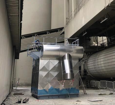
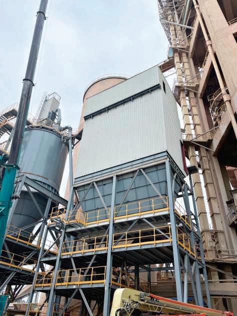
speaking with other owners, and seeing the equipment in action all help establish a strong foundation of trust and partnership. Transparency plays a crucial role, and customers should be aware of how thyssenkrupp Polysius’ past experiences – both positive and negative – shape the success of their project and decision-making.
thyssenkrupp Polysius is consistent throughout every phase of the project. Whether in the proposal or construction phase, the same team will be involved, promoting continuity, clear communication, and smooth collaboration.
thyssenkrupp Polysius can deliver service value and experience, with commitment continuing even after the plant is operational.
thyssenkrupp Polysius has been servicing the industry for 160 years by providing customers with long-lasting assets.
This commitment continues to drive thyssenkrupp Polysius today.
By adopting the Grey Build approach as best practice, it is recognised that effective projects are those built on engineering simplicity that stands the test of time. Informed decisions lead to solutions that are both dependable and effective.
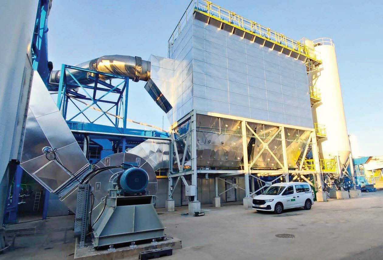

ABC
www.abc.org.uk
alcemy GmbH www.alcemy.tech
Alimak www.alimak.com
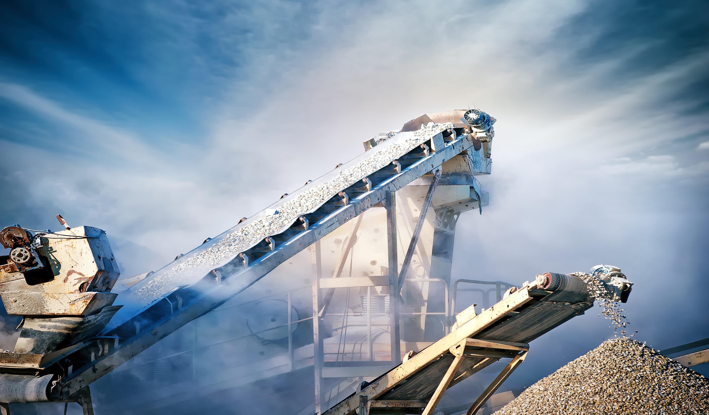
ASGCO www.asgco.com
ATD Abbausysteme GmbH www.atd-cardox.de
BOLDROCCHI
www.boldrocchigroup.com
Bricking Solutions
www.brickingsolutions.com
CalPortland www.calportland.com
CEMENGAL
www.cemengal.com
Christian Pfeiffer www.christianpfeiffer.com
Cinar Ltd www.cinar.co.uk
Cintasa www.cintasa.com
Claudius Peters www.claudiuspeters.com
Coperion www.coperion.com
DCL www.dclinc.com
Dracyon Corp www.dracyoncorp.com
Endress + Hauser www.endress.com
ENOTEC
www.enotec.com
ES Processing www.es-processing.com
ETS, Inc www.etsi-inc.com
Euromecc s.r.l www.euromecc.com
Everlasting Valve Company www.everlastingvalveusa.com
FLSmidth Cement www.flsmidth.com
Gebr. Pfeiffer, Inc www.gebr-pfeiffer.com
Gorco S.A gorco.es
HÄGGLUNDS
www.hagglunds.com
HASLE Refractories www.hasle-refractories.com
HEKO www.heko.com
IEEE-IAS/PCA Cement Conference www.cementconference.org
KOMATSU www.komatsu.com
Krosaki Group krosaki.eu
Lechler USA www.lechlerusa.com
Loesche www.loesche.com
Lubrication Engineers www.lelubricants.com
MAAG maag.com
Maerz Ofenbau AG www.maerz.com
Martin Engineering www.martin-eng.co.uk
Mole•Master www.molemaster.com
NAK Kiln Services nak-kiln.com
PENTA www.penta.net
PSCL www.pscl.com
Refra Technik refra.eu
Regal Rexnord www.regalrexnord.com
Ripik www.ripik.ai
Sika www.sika.com
ThermoFisher Scientific www.thermofisher.com
Unitherm Cemcon www.unitherm.at
Vortex Global www.vortexglobal.com
Wahl Refractories www.wahlref.com
World Cement www.worldcement.com


As the innovative and passionate world leader in the design and construction of kilns for the lime industry, it’s our aim to protect our planet and help our customers act responsibly. This has led to another milestone in our history – the Maerz EcoKiln® series. Its ability to enrich the CO2-content in the off-gas up to 95% gives you the full flexibility to choose the right downstream equipment for processing the CO2 for either sequestration or further utilisation.
maerz.com