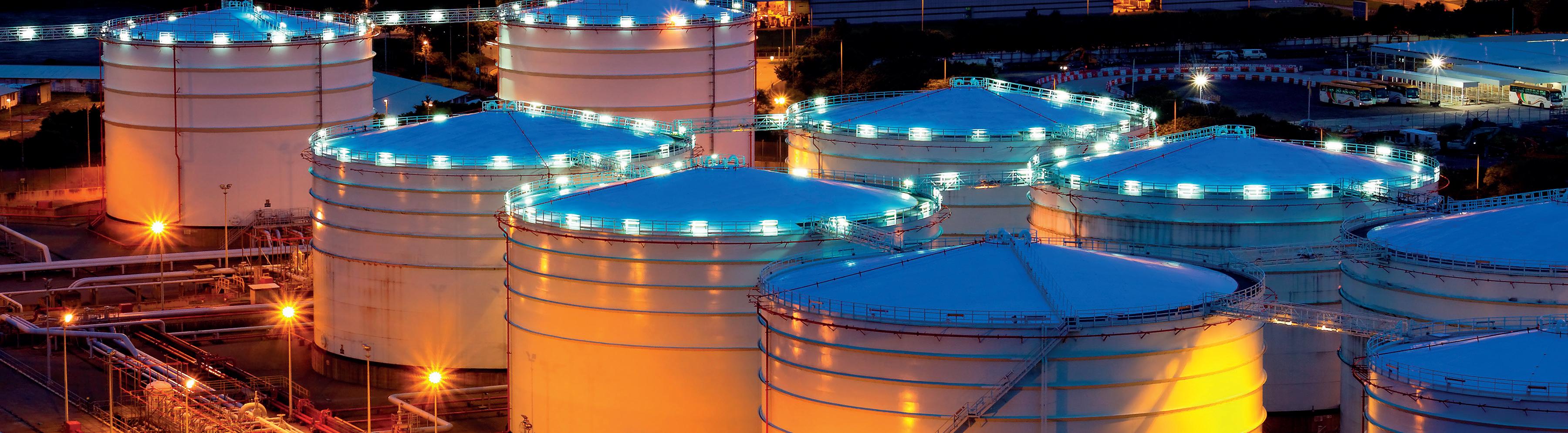
SPRING 2 024

Ammonia storage systems carry significant consequences, making thorough inspections crucial. Determining the right inspection strategy for a particular tank can be difficult when balancing inspection techniques with any identified damage to date and potential damage mechanism propagation. With E²G | The Equity Engineering Group, Inc., you can gain confidence in your ammonia tank inspection strategy and frequency. Our comprehensive approach enhances confidence in inspection results, empowering you to make informed decisions.
E²G delivers a multi-disciplinary approach that leverages API 581 risk-based inspection (RBI), European Fertilizer Manufacturer’s Association (EFMA) qualitative RBI, advanced probabilistic analysis, and finite element analysis (FEA) to offer a better understanding of the expected probability of failure.
Choose E²G for an optimized ammonia tank inspection strategy that is focused on safety and reliability.
03 Guest comment
05 World news
06
Gordon Cope, Contributing Editor, gives an overview of the upheaval seen across the energy storage sector in Europe, Africa and the Middle East, due to political, environmental and technological developments.
11
Ben Safavinia and Harold Laurence, Trinity Consultants, examine the US Environmental Protection Agency’s proposed New Source Performance Standard subpart Kc for storage tanks.
16
Alberto Feletto, Daniel Devò, Edoardo Marangoni and Alessandro Gerotto, Gerotto Federico Srl, Italy, provide an overview of what ATEX, IECEx and UL certifications are and why triple certification is advantageous for tank cleaning robots.
21
Chris Platt, Re-Gen Robotics, discusses how robots can improve the safety and enhance the efficiency of the tank cleaning process.
25 Automated surface cleaning
Jordan Koster, Jetstream of Houston LLP, describes the benefits and potential applications of implementing automated tank cleaning systems.
29
Cleaning up the industry
Dr Megan Pearl, Locus Bio-Energy, analyses the challenges present when cleaning storage tanks, and discusses the benefits offered by biosurfactant-based cleaners.


33 Improving supply chains
Toni Käsbeck, Endress+Hauser, explains how Inventory Management Systems (IMS) can help to optimise processes when handling bulk liquids.
37 Optimising LNG performance
Jon Taylor, Rotork, provides insight into the strategies that LNG terminals can use to optimise performance and prolong lifespan through efficient flow control and effective maintenance.
40 Q&A with Johns Manville
Tanks & Terminals talks to Mel Rasco, Foam Sales and Technical Manager, Johns Manville, about the importance of insulation systems in cryogenic applications.
43 Insulating LNG facility basins
Robert English, Owens Corning, discusses the benefits of installing proper LNG impounding pit insulation and how it prevents leaks or cracks from developing.
47 Turning up the heat
Carles Ferrer, Pirobloc, explains why it is necessary to implement thermal heating solutions for oil tank storage.
53 Safety sealed
Julian Yeo, United Electric Controls, and Saurabh Sanghavi, Vimal Fire Controls, discuss the crucial role of instrumentation in a rim seal fire protection system.
57 Intelligent grounding equipment
Dr Alexander Zelck, TIMM Technology Germany, explores how proper grounding and overfill prevention increases terminal safety and performance.
60 Breakthrough sensor developments
Juha Saily, PhotonTecTM, USA, explains how new fluorometric sensor technology can help to enhance liquid hydrocarbon leak monitoring.
64 Q&A with Chart Industries
Tanks & Terminals sits down with Paul Shields, Marketing Director Europe, Chart Industries, to explore the role that tank storage will play in the energy transition.
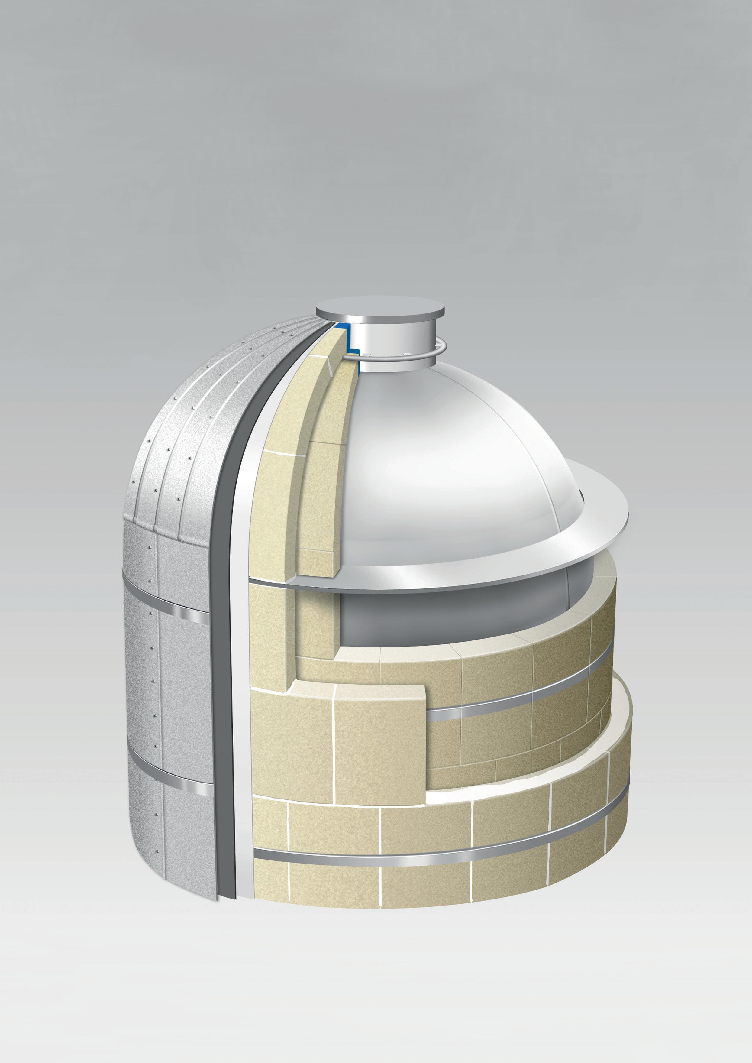
There are a lot of parts that go into a well-designed insulation system for LNG, as shown on this issue’s front cover, courtesy of Johns Manville. More detailed illustrations and guidance on insulating a complete cryogenic or LNG insulation system can be found at jm.com/en/industrial-insulation/


MANAGING EDITOR James Little
SENIOR EDITOR Callum O’Reilly callum.oreilly@palladianpublications.com
EDITORIAL ASSISTANT Oliver Kleinschmidt oliver.kleinschmidt@palladianpublications.com
SALES DIRECTOR Rod Hardy rod.hardy@palladianpublications.com
SALES MANAGER Chris Atkin chris.atkin@palladianpublications.com
SALES EXECUTIVE Sophie Barrett sophie.barrett@palladianpublications.com
PRODUCTION MANAGER Kyla Waller kyla.waller@palladianpublications.com
EVENTS MANAGER Louise Cameron louise.cameron@palladianpublications.com
DIGITAL EVENTS COORDINATOR Merili Jurivete merili.jurivete@palladianpublications.com
DIGITAL CONTENT ASSISTANT Kristian Ilasko kristian.ilasko@palladianpublications.com
DIGITAL ADMINISTRATOR Nicole Harman-Smith nicole.harman-smith@palladianpublications.com
ADMIN MANAGER Laura White laura.white@palladianpublications.com
CONTRIBUTING EDITORS Nancy Yamaguchi Gordon Cope
ASUBSCRIPTION
APPLICABLE

s 2024 gets underway, the new year marks an opportunity for the bulk liquid terminal industry to take a wider view of the global energy market. While products like oil and gasoline remain the clear majority in the stock of all bulk liquid goods, cleaner low-carbon forms of energy such as liquid hydrogen, liquid ammonia, and biofuels (e.g. ethanol) are playing an increasing role in the day-to-day energy supply chain.
Bulk liquid terminals the critical storage and logistics nodes for these products as they make their way from producer to consumer are poised to play a more pivotal role now and well into the future.
In the US, policy makers in Washington D.C. have started to notice and meaningfully support this shift. Both state and federal actors seek to capitalise on the funding provided for clean energy initiatives through laws like the 2022 Inflation Reduction Act and the Infrastructure Investment Jobs Act. In 2023 alone, for example, the US Department of Energy (DOE) announced US$8 billion for its Regional Clean Hydrogen Hubs Program (H2Hubs), which will create networks of hydrogen producers, consumers, and local connective infrastructure to accelerate the use of hydrogen.1 Likewise, the US Department of Agriculture (USDA) announced another US$500 million in funding to make biofuels more available to US consumers.2
Globally, organisations like the United Nations (UN) and its convenings like the Global Climate Change Conference (COP28) in Dubai, UAE, have offered the chance for leaders to outline a low-carbon future through international agreements and pacts. The body even went so far as to signal “the beginning of the end” of the fossil fuels era.3 Similarly, the International Renewable Energy Agency (IRENA) signed an agreement with DP World, a UAE-based global supply chain solutions company, to collaborate on decarbonising the global shipping and ports sectors.4
Terminal companies, however, must still overcome unique challenges to embrace this transition in bulk liquid goods. Hydrogen, as one of the current front-runners in the low-carbon transition, can be converted from its regular gaseous form to a liquid, through a costly liquefaction process. It must also be stored at incredibly cold temperatures, adding a logistical hurdle to its journey through the supply chain.
As an alternative, liquid ammonia is more readily available, is easier to store (as it does not need to be kept nearly as cold), and has a higher energy density than liquid hydrogen (11.5 MJ/l to 8.5 MJ/l). Ammonia production, however, is far from green and makes up 1 – 2% of global carbon emissions, undermining its value as a low-carbon source – at least in the short-term.5
In the end, a true and long-lasting move away from fossil fuels will require persistent effort from the public, government leaders, and businesses alike. As a critical component in this endeavour, terminal companies and the ILTA remain committed to meeting the challenges of tomorrow and stand ready to play a prominent role in the global energy market long into the future.
1. https://www.energy.gov/oced/regional-clean-hydrogen-hubs-0
2. https://www.usda.gov/media/press-releases/2023/06/26/biden-harris-administration-announcesfunding-homegrown-biofuels
3. https://unfccc.int/news/cop28-agreement-signals-beginning-of-the-end-of-the-fossil-fuel-era
4. https://www.irena.org/News/pressreleases/2023/Nov/IRENA-and-DP-World-Join-Forces-toAdvance-Decarbonisation-Solutions-for-Ports-and-Maritime-Logistics
5. https://e360.yale.edu/features/from-fertilizer-to-fuel-can-green-ammonia-be-a-climate-fix


A selection of the latest news hitting the headlines on www.tanksterminals.com
Vopak and Neste form strategic partnership
New deal strengthens UK natural gas supply
Tanks & Terminals spoke with Dandee Bacani, Manager for the Marketing Department at Endress+Hauser Level+Pressure Japan, about his article that featured in the Summer 2023 issue of Tanks & Terminals magazine. Scan the QR code to watch the interview in full.
READ MORE...

DIARY DATES
StocExpo Rotterdam, the Netherlands www.stocexpo.com
03 05 April 2024
26th Annual International Aboveground Storage Tank Conference & Trade Show Orlando, Florida, USA www.nistm.org
06 08 May 2024
ILTA Conference & Trade Show Houston, Texas, USA www.ilta.org
26 27 June 2024
Downstream USA Galveston, Texas, USA events.reutersevents.com/petchem/downstream-usa
17 20 September 2024 Gastech Houston, Texas, USA www.gastechevent.com
07 10 October 2024
API Storage Tank Conference & Expo Fort Lauderdale, Florida, USA events.api.org/2024-api-storage-tank-conference-expo
10 12 December 2024
17th Annual National Aboveground Storage Tank Conference & Trade Show
The Woodlands, Texas, USA www.nistm.org


Gordon Cope, Contributing Editor, gives an overview of the upheaval seen across the energy storage sector in Europe, Africa and the Middle East, due to political, environmental and technological developments.
The energy sector is used to major challenges, but rarely does it experience so many at once. Geopolitical risk is in the red zone in the Middle East and Europe; the costs of the worldwide shift to a low-carbon economy are stratospheric, and nobody has any real idea if our grandchildren will be driving vehicles powered by fossil fuels, hydrogen or electricity. While uncertainty is rife, opportunities for the storage sector abound.
Europe is still scrambling to replace the 150 billion m³ of gas formerly supplied by Russia. Germany, for instance, has commissioned floating LNG regasification facilities in northern ports. Larger, land-based LNG terminals are also in the offing, with new facilities coming on-stream over the next several years at Wilhelmshaven, Stade and Brunsbuttel. GlobalData, a consultancy, notes that 30 newly announced, and planned regasification terminals are expected to commence operations in Europe by 2030.
LNG is not the silver bullet, however. During the scramble to fill gas storage ahead of winter 2022, a strange phenomenon occurred; LNG tankers began to stack up as gas storage exceeded 90% capacity. Much was made of the fact that the EU has only enough gas storage for a few months at most during heavy usage throughout the winter.
But a few calculations comparing North America to Europe largely exonerates gas storage as a culprit. The US and Canada consume more than 3 billion m³/d of gas and possess slightly more than 150 billion m³ of storage, which would theoretically last seven weeks if significant domestic producing sources were compromised. The EU, in contrast, consumes around 1.1 billion m³/d of gas yet has 90 billion m3 of storage (which would last three months).
While this is like comparing apples and oranges, significantly upping EU storage (such as recommissioning the 1.5 billion m³ Rough storage facility in the UK), would only be part of the solution.
There is a pressing need for pipeline interconnectivity so that gas can be transported to major consuming regions with greater efficiency and flexibility. In September 2022, the Baltic Pipe was officially commissioned; the 275 km line connects Norway’s North Sea natural gas network through a series of underwater and surface segments to Poland. This European gas supply corridor could deliver up to 10 billion m³/yr, helping to reduce Poland’s dependence on coal for electricity.
The new, 182 km Interconnector Greece Bulgaria (IGB) line will possibly deliver up to 5 billion m³/yr from the Southern Gas Corridor system that transports Azeri gas to Europe.
The EU is also betting heavily on hydrogen. When burned, the energy-dense fuel emits only water; it can be created virtually anywhere, eliminating coercion by unfriendly suppliers; and it has low-carbon credentials when produced by electrolysis using electricity from solar panels and wind farms. In March 2023, the Dutch government officially designated a site for the world’s largest offshore hydrogen production project; the Ten noorden van de Waddeneilanden (the North of the Wadden Islands). The site, which has the potential for 700 MW of energy generation, will be connected to Gasunie’s 1200 km hydrogen pipeline network. In July 2023, Germany announced that it would develop over 11 000 km of ‘core’ hydrogen pipelines. It has charged FNB, the group of transmission operators shipping gas across the country’s 16 states, with delivering the network and infrastructure by 2032. Primary customers include steel furnaces, fertilizer plants, chemical producers and refineries; because pure hydrogen makes natural gas infrastructure brittle, much of the new network, including tanks and terminals, will have to be new-build.
As a case in point, Evolution Terminals announced it was in advanced development of North-western Europe’s first import, storage and handling terminal for hydrogen carriers, renewable energy products and low-carbon fuels. The first phase of development involves spending €450 million on a 16.4 ha. site at the Netherland port of Vlissingen. Infrastructure will include 400 000 m³ of storage for green and low-carbon products and fuels, a new deep-water jetty, and truck and rail-loading facilities. Phases two and three include plans for storage expansion, and the building of an ammonia cracking facility to convert green ammonia to hydrogen. The US-based company is currently seeking regulatory approvals with Dutch authorities.
Africa suffers from a deficit of energy infrastructure, but that is slowly changing. In Nigeria, the country of 213 million relies heavily on propane to meet household heating and cooking needs with recent estimates place consumption over 1 million tpy. In November 2023, Masters Energy Oil and Gas Ltd announced a US$500 million LPG project, which includes the construction of a 20 000 t gas storage unit in Port Harcourt, and over 200 gas refilling outlets and 2000 gas-exchange outlets situated throughout the country. The company, which is also involved in utilities, petrochemicals, dredging and shipping, did not designate a completion date.
In November 2023, Eni announced that it would spend US$10 billion developing the Baleine field, located in Ivory Coast’s offshore waters, approximately 50 km southeast of the capital of Abidjan. Reserves are estimated at 2.5 billion bbl of oil and 3.3 trillion ft³ of natural gas. Discovered in 2021, the field came online in August 2023, with production of 30 000 bpd. The new investment is
intended to boost production to roughly 200 000 bpd by 2027, primarily for export. In addition, the field is expected to produce 200 million ft³/d of gas and 150 000 tpy of butane for domestic use. Until recently, the country produced less than 50 000 bpd; the new production will require a comprehensive expansion of infrastructure in Abidjan’s port.
In Egypt, government-owned Red Sea Refining and Petrochemicals is building the Tahir refinery and petrochemicals plant in the Suez port of Ain Sokhna. When completed later in the decade, the US$7.5 billion complex will have the capacities of 1.5 million tpy of ethylene and around 600 000 tpy of propylene, largely for export.
Several major projects to improve goods and energy movement in ports and terminals are underway in Africa. Angola’s Sonangol is investing US$1.5 billion in the port of Barra do Dande. The project, with a completion date in mid-2024, will modernise old infrastructure and create new handling capacity for containers and bulk solids. It will also include approximately 580 000 m³ of onshore storage for imported gasoline, diesel and LPG. In late September 2022, Egypt’s Ministry of Petroleum and Mineral Resources (MOPR), launched an expansion of its major petroleum port in Al-Hamra. The port, located 120 km west of Alexandria, has six storage tanks with a capacity of 1.5 million bbl. The expansion will add an additional 1.1 million bbl of crude storage. Further phases foresee an expansion of the port to 5.6 million bbl capacity.
Rocked by rising prices for diesel and gasoline, African nations are also investing in green energy to create secure domestic supplies of fuels, as well as valuable exports. In June 2023, South Africa announced its SA-H2 Fund, an initiative to raise US$1 billion to accelerate the development of its green hydrogen sector. The fund, a mix of government, private and NGO investors, would fast-track the building of large-scale green infrastructure to take advantage of the country’s sun, wind and mineral resources. In August 2023, several international construction firms, including AP Moller-Maersk and Bouyges SA, expressed interest in tendering on the contract for the development of the US$2.6 billion port of Boegoebaai, located in northwest South Africa. The port and related rail project would facilitate the export of hydrogen and low-carbon products to international destinations.
In May 2023, the government of Namibia announced that German-based Hyphen Hydrogen Energy was the preferred bidder for the US$10 billion green hydrogen project located in the Namib Desert’s Tsau/Khaeb National Park. The facility would draw on abundant solar power to produce up to 2 million tpy of green ammonia for shipment from the nearby Atlantic port of Luderitz to European markets (which would require major tank and terminal upgrades).
Egypt’s Suez Canal Zone (SCZONE) is considered an ideal region to make green hydrogen through electrolysis due to its high wind and solar intensity. Some analysts have predicted that large projects could produce it for under US$1/kg. In late 2022, the government of Egypt issued two ‘golden licences’ to two green hydrogen facilities located in Ain Sokhna (a golden licence grants full
The only deep water platform (64’ operating draft) on the U.S. East
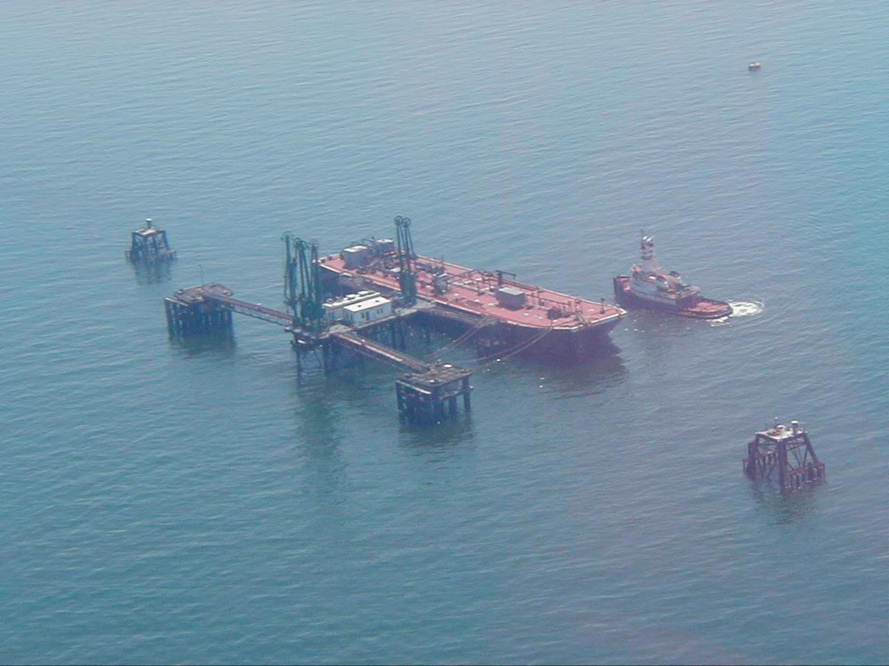
• 20 storage tanks 80 miles East of New York Harbor
• The only deep-water loading/ unloading platform on the U.S. East Coast.
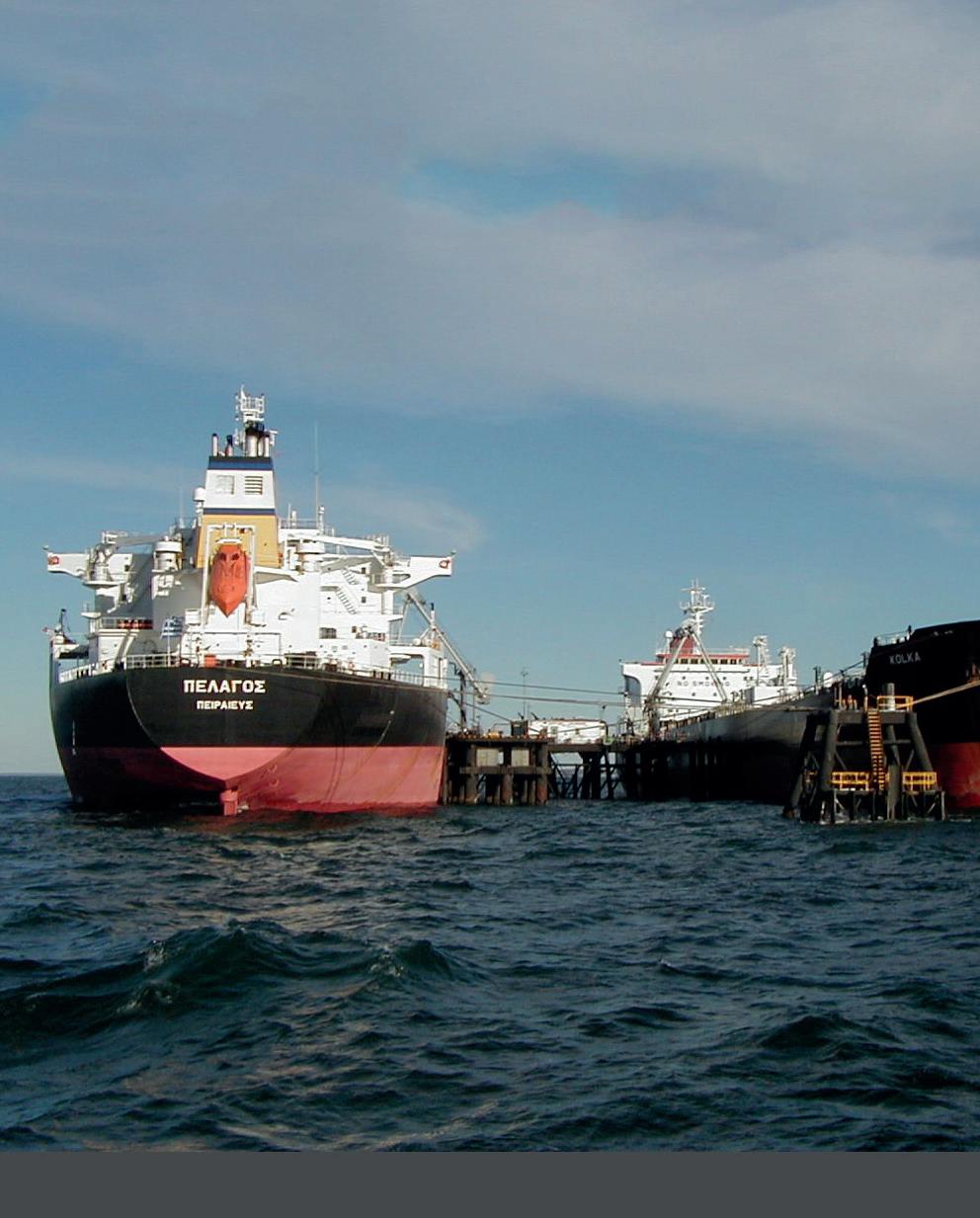
• Total Storage Capacity of 5 Million Barrels
• Easy reloading for distribution of product to U.S., Canada and Europe

approval in one single step, from right-to-operate to building permits). The first, at a modest cost of US$5.5 billion, will produce 1 million tpy of green ammonia from renewable hydrogen. The second is slated to produce close to 90 000 tpy of green ammonia.
In June 2023, Aramco and TotalEnergies announced that Hyundai Engineering & Construction, Maire Tecnimont, Sinopec Engineering and other companies had been awarded a total of US$11 billion in engineering, procurement and construction (EPC) contracts for the Amiral petrochemicals expansion at its SATORP refinery in Jubail, Saudi Arabia. The expansion will include one of the largest mixed-load steam crackers in the Middle East, with a capacity of 1.6 million tpy of ethylene and other industrial gases for domestic and export markets.
In October 2023, Chevron Phillips Chemical Co. and QatarEnergy announced that they had secured US$4.4 billion in financing for the Ras Laffan Petrochemicals project from various lenders. The US$6 billion complex, to be built by Samsung and partners, will include a 2.1 million tpy ethane cracker and two polyethylene trains with a combined output of 1.7 million tpy. When the plant comes online in 2026, it will raise the country’s petrochemical production capacity to almost 14 million tpy.
Middle East producers are also eager to participate in the nascent low-carbon fuel sector, specifically green hydrogen and green ammonia; consumers in Europe are keen on both for fuel production. Saudi Arabia intends to build an immense green ammonia plant in the NEOM project, a futuristic greenfield development in the country’s northwest, home to abundant solar and wind resources. The US$5 billion plant would produce up to 650 tpd ( which equates to 240 000 tpy). In the UAE, state-owned subsidiary Fertiglobe is also developing a greenfield project, which will be a 1 million tpy low-carbon ammonia plant in Abu Dhabi’s Ruwais industrial complex.
In July, 2023, the UAE announced its national H2 strategy that would see the production of 1.4 million tpy of green hydrogen by 2031, and 15 million tpy by 2050. The federation will develop two hydrogen hubs at still-unspecified locations at a cost of approximately US$16 billion, with a plan to develop another three by 2050. It currently has over two dozen submitted project proposals, seven of which have reached final investment decision (FID).
Moreover, Oman has laid plans to produce 1 million tpy of renewable hydrogen by 2030, 3.75 million tpy by 2040 and around 8.5 million tpy by 2050, with the intention of exporting the majority in various forms of ammonia. Analysts note that the country, which exports 200 000 tpy of grey ammonia products, would need to spend tens of billions in order to massively expand its terminals capacities.
While Europe’s pivot to LNG and hydrogen may seem like an excellent short-term solution to replacing Russian gas, placing all one’s eggs in a limited number of baskets is
never a good idea. LNG prices can (and do) spike with alarming regularity, and much of the hydrogen economy has yet to show economic viability as upfront cost estimates for production capacity and infrastructure trend towards the trillions of dollars. In January 2024, a study commissioned by Germany’s INES storage group cast doubt upon government estimates of envisaged hydrogen use of 279 TWh/yr by 2032, estimating instead that the demand might be as little as 73 TWh; this difference in capacity outlines the uncertainties and financial risk of expensive overcapacity.
Progress in Africa is compromised by needless complications. A case-in-point is the state of refining in Nigeria. For decades, the refineries of the Nigerian National Petroleum Co. (NNPC) have run at well below capacity, resulting in the export of 1.4 million bpd of crude and subsequent import of hundreds of thousands bpd of expensive diesel and gasoline. The greenfield, 650 000 bpd Dangote refinery is seen as a solution; after years of delay and cost escalations, it was formally inaugurated in May 2023. But supplying the privately-owned refinery with feedstock is a challenge; by January 2024, the refinery had acquired approximately 6 million bbl of crude on hand, enough to begin operations. NNPC announced it would supply four crude cargoes from its February 2024 programme; the refinery has indicated that it is looking at other countries to supply crude, as well.
The Middle East, of course, is rife with geopolitical risk. Iran seeks to disrupt nations throughout the region with proxies such as the Houthi and Hamas. Saudi Arabia, Kuwait, Qatar, the UAE and other Gulf countries are constantly wrangling when fields overlap borders. OPEC is perennially threatened with cartel sanctions by the US Congress. Tankers are attacked and seized without warning, and refinery, pipeline and petrochemical assets are hit with drones and rockets. Such constant threats drive up the risk costs and compel countries to spend inordinate amounts on military equipment and armies, rather than on developing terminal infrastructure.
The hydrogen economy may find itself hopelessly mired in ‘next decade’ syndrome, in which advances in electrolysis and solar power are promised to reduce its cost to parity with traditional manufacturing methods ‘within the next decade’. On the other hand, geologists are discovering massive deposits of natural hydrogen in France and around the world, with the potential to drop prices for carbon-free hydrogen precipitously.
In conclusion, the Ukraine war and regional military disputes have shown with great clarity the ability of disruptive events to massively reshape the energy landscape in every region of the world, including Europe, the Middle East and Africa. While hardship and tragedy are the main outcomes of such events, they also present opportunities as countries strive to adjust to new realities and to seek more secure supplies of energy. For better or worse, those opportunities represent both tremendous challenges and prospects for the storage sector.
Ben Safavinia and Harold Laurence, Trinity Consultants, examine the US Environmental Protection Agency's proposed New Source Performance Standard subpart Kc for storage tanks.
On 4 October 2023, the US Environmental Protection Agency (EPA) proposed the New Source Performance Standard (NSPS) Subpart Kc for volatile organic liquid storage vessels (including petroleum liquid storage vessels), the EPA’s first NSPS for this equipment type in 40 years. The EPA is expected to finalise NSPS subpart Kc by a court-ordered date of 30 September 2024. The new regulation
will apply to storage tanks in the volatile organic liquid (VOL) service that commence construction, reconstruction, or modification after 4 October 2023. In the subpart, the EPA proposes a broad, unprecedented approach to determining when a tank becomes subject to the rule by ‘modification.’ Among other changes, the EPA also proposes to require more stringent emission control requirements for certain tanks, annual Lower Explosive Limit (LEL) monitoring within internal floating roof (IFR) tanks, and control of degassing events.
The EPA promulgated NSPS subpart K, specific to storage vessels for petroleum liquids, in 1974.¹ These standards were amended several times before 1980, when the EPA proposed to establish a revised NSPS for storage vessels for petroleum liquids as NSPS subpart Ka.² In 1982, the EPA published a list of priority sources for which additional NSPS should be established, and VOL storage vessels at synthetic organic chemical manufacturers were included in the priority list.³
In 1987, the EPA promulgated an emission standard for VOL storage vessels (including petroleum liquid storage vessels) for which construction, reconstruction, or modification began after 23 July 1984, as NSPS subpart Kb. This subpart regulates storage vessels with a capacity of approximately 75 m³ (~20 000 gal.) or more that store VOLs with a true vapour pressure over 15.0 kPa (2.18 psia), and from storage vessels with a capacity of 151 m³ (~40 000 gal.) or more that store organic liquids with a vapour pressure over 3.5 kPa (0.51 psia). NSPS subpart Kb required storage vessels with the following parameters to install emission controls that included the use of either an IFR, an external floating roof (EFR), or a closed vent system and a control device:
n A capacity of 75 m³ (~20 000 gal.) or more that store VOLs with a true vapour pressure of 27.6 kPa (4.0 psia) or greater.
n A capacity of 151 m³ (~40 000 gal.) or more that store organic liquids with a true vapour pressure of 5.2 kPa (0.75 psia) or greater.
Subpart Kb also required the use of a fixed roof tank with a closed vent system and emission control device for the storage of organic liquids with a true vapour pressure of 11.1 psia or greater.
The standards set in NSPS subpart Kb for storage vessels with an EFR or IFR are a combination of design, equipment, work practice, and operational standards. These standards require, for tanks complying using a floating roof, that a rim seal be installed continuously between the inner wall of the vessel and the floating roof to prevent VOC emissions from reaching the atmosphere. Subpart Kb also contains several requirements for fittings on the floating roof.
The following tanks will be subject to emission requirements set forth in NSPS subpart Kc:
Storage tanks with capacities between 20 000 and 40 000 gal. which store liquids with a maximum true vapour pressure greater than or equal to 1.5 psia and
storage tanks with capacity greater than or equal to 40 000 gal. which store liquids with a maximum true vapour pressure greater than or equal to 0.5 psia that is used to store VOL for which commence construction, reconstruction, or modification after 4 October 2023.4
The thresholds requiring emission control are lower in the proposed rule than in subpart Kb. The EPA’s proposed threshold for tanks with a capacity of 40 000 gal. or greater is 1.5 psia (contrast 4.0 psia in subpart Kb); for tanks of capacity 20 000 – 40 000 gal., the proposed threshold is lower at 0.51 psia (contrast 0.75 psia in subpart Kb). Also, unlike subpart Kb, the proposed NSPS subpart Kc affected facility definition does not exempt certain tanks above the 20 000 gal. capacity based on maximum true vapour pressure. Any VOL tank above 20 000 gal. in capacity, and constructed, modified, or reconstructed after 4 October 2023, must compare its maximum true vapour pressure to the emission control thresholds.
Most exemptions from subpart Kb based on equipment type are continued under the proposed subpart Kc. Exemptions include mobile vehicle vessels, pressure vessels of 204.9 kPa (29.7 psia) or greater, petroleum or condensate vessels prior to custody transfer, beverage alcohol storage vessels, and vessels at bulk gasoline plants and service stations. The EPA proposes not to carry forward the exemption for vegetable oil storage vessels regulated by 40 CFR 63 subpart GGGG. 5
Existing storage vessels become subject to the new NSPS only when they are ‘modified,’ or ‘reconstructed,’ as those terms are used in 40 CFR part 60. 6 Under NSPS subpart Kb, the EPA has held that storage vessel ‘modifications’ are rare, because construction specifications of the vessel rarely need to be changed to accommodate various liquids. 7 The EPA’s rule proposal anticipates a similarly low rate of modifications, but the proposed text is open to interpretations that would heavily accelerate the number of tanks ‘modifying’ into subpart Kc. 8 The proposed rule text holds that “if the storage vessel is used to store a VOL that has a higher maximum true vapour pressure than the VOL previously stored,” 9 the vessel is modified. 10 This approach departs starkly from the EPA’s policy of over 40 years.
The EPA is proposing performance standards to the Best System of Emission Reduction (BSER) as well as alternative compliance standards for affected storage vessels. Many of the NSPS subpart Kc standards follow standards established in NSPS subpart Kb, or render them more stringent.
For storage vessels storing VOL with maximum true vapour pressures less than 11.1 psia, the EPA proposes the following standards of performance for newly constructed and reconstructed IFRs:
n For a new or reconstructed tank, an IFR with a liquid-mounted or a mechanical shoe seal primary seal and a rim-mounted secondary seal. 11

n For a new or reconstructed tank, an EFR with a liquid-mounted or a mechanical shoe seal primary seal and a rim-mounted secondary seal, welded deck seams, an unslotted guidepole with gasketed sliding cover and pole wiper may be used. If a slotted guidepole is used, a liquid mounted primary seal is required and the slotted guidepole must have a gasketed sliding cover, pole sleeve and pole wiper (with or without float). 12
For storage vessels with maximum true vapour pressures greater than or equal to 11.1 psia, the EPA is proposing to determine that the BSER is a closed vent system and control, and the standard of performance reflecting the BSER is a 98% weight or greater reduction in VOC emissions. The weight percent in NSPS subpart Kc is greater than the 95% in NSPS subpart Kb.
The EPA is proposing new rim seal requirements for IFR tanks, aligning EFR and IFR standards: a primary seal of either liquid-mounted or mechanical shoe seal type, with a rim-mounted secondary seal.
As stated above, the EPA proposes that new or reconstructed EFR tanks either use no slotted guidepole, or a liquid-mounted rim seal. However, slotted guidepoles are often used for essential purposes such as fuel sampling or level gauging. Whereas replacing a liquid-mounted rim seal with shorter service life would require a roof landing, causing emissions.
NSPS subpart Kc also includes numerous design requirements for deck fittings on floating roofs. Unlike subpart kb, the proposed subpart would require bolts on access hatches and gauge float wells, and would prohibit the use of slit fabric seals on gauge hatch sample wells. 13
The EPA proposes controlled degassing for all fixed-roof tanks that use a control device for routine emissions. Based on cost effectiveness, the EPA selected a 1 million gal. capacity threshold for floating roof storage vessels: “Control degassing for storage vessels with a capacity of 1 million gal. or more storing organic liquids with a maximum true vapour pressure of 1.5 psia or more.” 14
The requirements set forth in NSPS subpart Kc need to be met until the vapour space in the storage vessel is measured to be less than 10% of its LEL. 15
The EPA proposes that affected IFR storage vessels use an LEL monitor as a supplement to visual inspection, with an action threshold of 25%. 16 If a concentration reading exceeds 25% for the highest 5-minute period within a 20-minute monitoring period, the result would
be considered an inspection failure similar to a visual inspection failure.
For storage tanks using a closed vent system (CVS) to route routine emissions to a control device, fuel gas system, process, or flare, the EPA proposes several requirements, including initial and annual leak inspections for the CVS; bypass prevention practices such as a car seal; and pressure relief device monitoring. 17
The EPA proposes reporting requirements including initial notifications and semi-annual reports. In contrast to Part 63 NESHAP, the EPA proposes that subpart Kc tank owners or operators would be subject to different semi-annual reporting timeframe windows for individual storage vessels. 18 Tracking the reporting timeframes for each tank could create additional compliance burden for owners and operators.
The EPA has proposed substantial changes to air emission standards for VOL storage vessels. The proposed changes include revisions to the definition of modification, a new set of emission standards, seal and fitting requirements, and reporting requirements. Understanding that requirements are not final, tank owners and operators should begin assessing whether tank projects will be subject, and should begin developing compliance strategies.
1. 39 Fed. Reg. at 9317 (8 March 1974).
2. 45 Fed. Reg. at 23379 (4 April 1980).
3. 47 Fed. Reg. at 951 (8 January 1982).
4. 88 Fed. Reg. at 68535 (4 October 2023).
5. 40 CFR 60.110b(d). Cf. proposed § 60.110c(b).
6. Cf. the definition of modification in § 60.2, “change in the method of operation of, an existing facility which increases the amount of any air pollutant” or in § 60.14(a) “operational change to an existing facility which results in an increase in the emission rate to the atmosphere of any pollutant to which a standard applies.”
7. 49 Fed. Reg. at 29707 (23 July 1984). EPA has historically applied the “alternative fuel or raw material” exemption of § 60.14(e)(4).
8. When EPA proposed NSPS subpart Kc, EPA expected 27 to 30 tanks to become ‘modified’ into the rule within five years. 88 Fed. Reg. at 68545; 68551. According to EPA’s cost basis for the proposed rule, thousands of tanks are subject to NSPS subpart Kb at present, and many more tanks have not yet been modified into a K series subpart. At stake is the rate at which tanks become ‘modified’ and enter subpart Kc.
9. Proposed § 60.110c(e).
10. In the proposal preamble for NSPS subpart Kc, EPA proposes that changing the stored liquid does not constitute a ‘‘use of an alternative fuel or raw material,’’ and § 60.14(e)(4) does not exempt service changes from the §§ 60.2 and 60.14 modification definition. 88 Fed. Reg. at 68544 (4 October 2023).
11. Proposed § 60.112c(b).
12. Proposed § 60.112c(c).
13. Proposed § 60.112c(b)(6), (7); (c)(2)(iv), (v).
14. Proposed Federal Register/Vol. 88, No. 191. Table 7.
15. Proposed § 60.112c(e).
16. Proposed § 60.112c(b)(16).
17. Proposed § 60.112c(d)(2) contains a detailed list of requirements.
18. Proposed § 60.116c(d).
VOL storage emissions standards are set to change in September 2024. trinityconsultants.com/software
BREEZE TankESP
The market-leading, desktop-based program, that uses emission estimation procedures from AP-42 Chapter 7 to calculate emissions from floating- and fixed-roof tanks.
BREEZE ESP+
Highly-anticipated, cloud-based solution including all TankESP capabilities plus ability to calculate emissions from:
f Catch Pans
f Combustion Units
f Control Devices
f Equipment Leaks

f Line/Vessel Openings
f Loading Operations
f Sumps/Oil-Water Separators
f Vacuum Trucks
Now is the time to prepare for the proposed NSPS changes by investing in tank emissions calculations software today.
When it comes to tank emissions calculations, we have you covered!


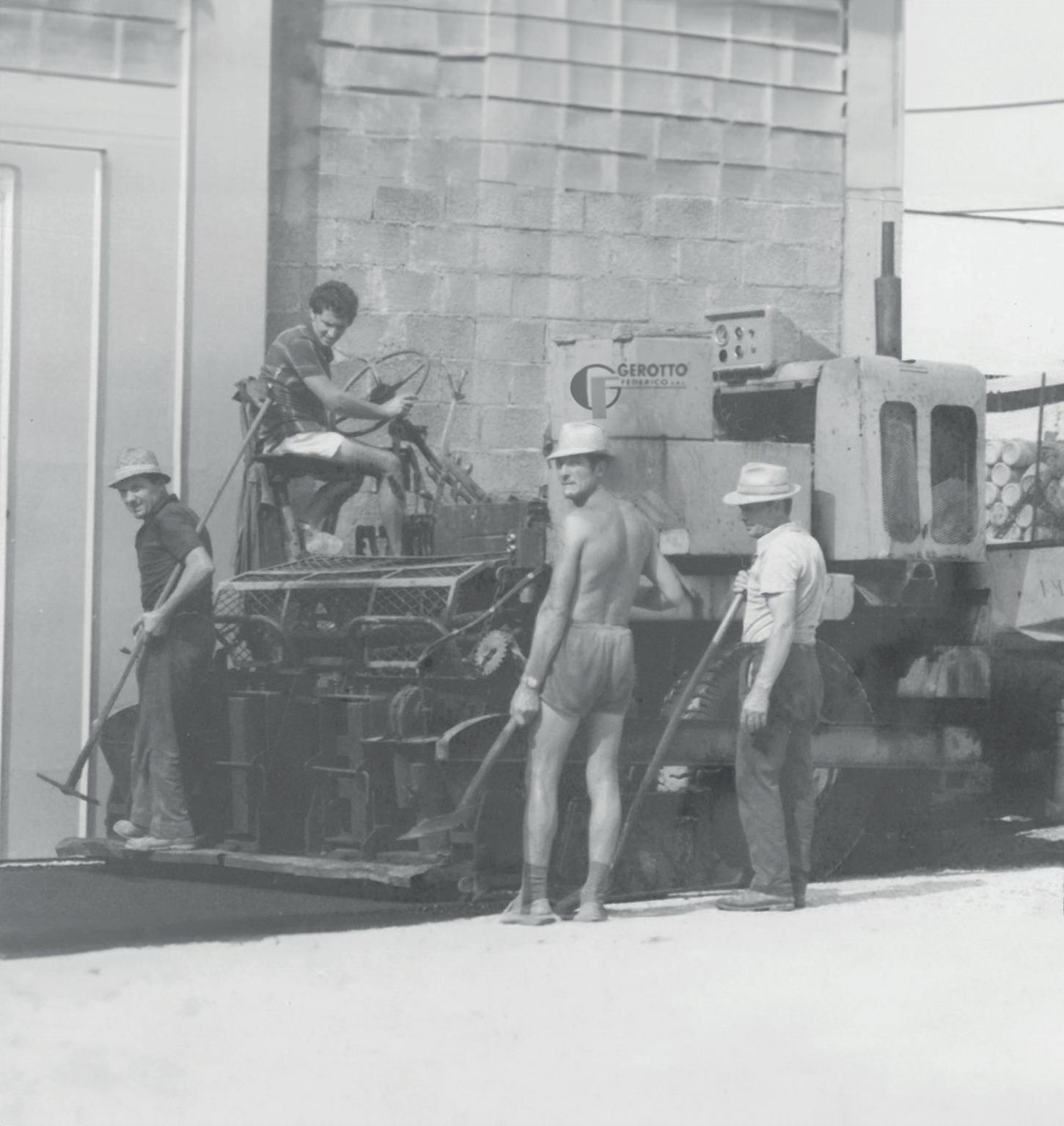
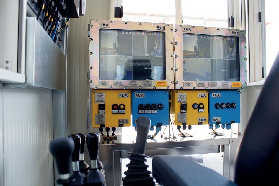
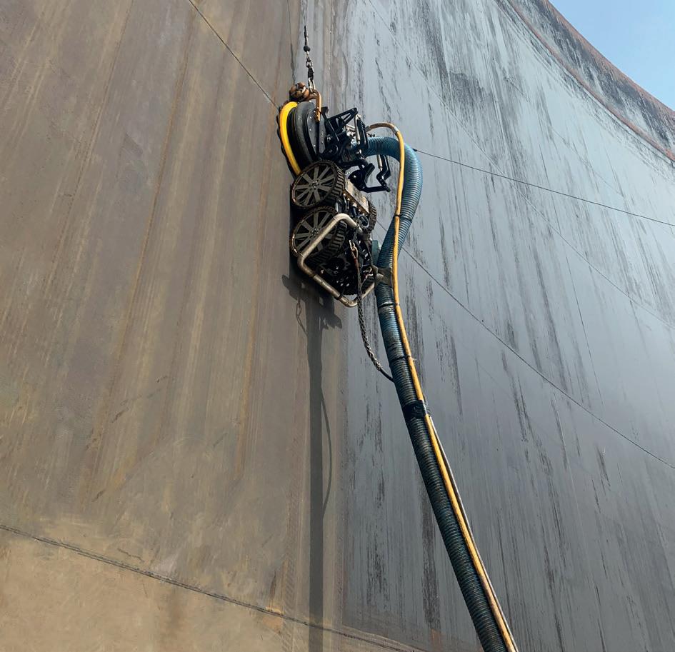
Alberto Feletto, Daniel Devò, Edoardo Marangoni and Alessandro Gerotto, Gerotto Federico Srl, Italy, provide an overview of what ATEX, IECEx and UL certifications are and why triple certification is advantageous for tank cleaning robots.
Safety standards are key to protecting employee health in the workplace. The increased focus on these issues has grown over the last 20 years, leading states, through notified bodies, to regulate machines and procedures more and more precisely to ensure that the chances of an accident are reduced to zero. This scenario is intertwined with the expansion of market globalisation that has led manufacturing companies to interface with customers and contractors at every latitude. Technical aspects, regulatory compliance, and market dynamics are consequently closely linked and determine precise design choices.
The name ATEX comes from the French ATmosphère EXplosibles, which describes the use of a product designed to be placed in an explosive atmosphere. ATEX certification is mandatory throughout Europe and involves all stages of its life cycle; from production, to the installation and use of the equipment. There are two parts: Directive 99/92/EC, which mainly focuses on the health and safety of people working in potentially explosive atmospheres and accounts for the correct selection, installation, inspection and maintenance of equipment; and Directive 2014/34/EU, which mainly concerns trade, considers equipment that will be used in potentially hazardous areas, and covers the manufacture and sale of ATEX equipment.
IECEx, on the other hand, stands for International Electrotechnical Commission Explosive. While ATEX is a mandatory application limited to Europe, IECEx is an international certification accepted in several countries to help build confidence in the safety of explosive equipment. It also facilitates international trade in equipment and services for use in explosive atmospheres.
In the case of machines, both standards apply not only to the individual product, but also certify that the company's entire production process can guarantee high performance in terms of production quality. For this, the company must have a quality system and undergo an audit to obtain a Quality Assurance Notification (QAN) under ATEX and a Quality Assurance Report (QAR) under the IECEx scheme. Both refer to ISO 9001 and EN 80079, which overlap in many respects.
For some important markets – the US and Canada for example – there is also the UL compliance, which is dedicated to the compliance of electrical components’ safety and that can overlap with the requirements of ATEX and IECEx.

The UL testing procedure encompasses the certification of personnel, products, facilities, processes, and systems. Testing is carried out by a team comprising support associates, field representatives, engineers, and technical support professionals.
The possibility of having more than one certification (ATEX, IECEx and UL compliance) for products has numerous advantages. The most obvious is the continuous increase in production quality. High standards demand high performance from manufacturers. At the same time, high standards are a safeguard for contractors and asset owners who can rely on qualified suppliers. Obtaining certification – and especially
maintaining it – imposes constant monitoring of production standards and constant supervision of the supply chain. These burdens for manufacturing companies, however, translate into reduced time to market for individual products, faster penetration of international markets, and optimisation of product certification time and costs.
There were 825 active refineries in 2023 with a projected capacity growth of 15% over the period 2023 – 2027.1 In Europe alone, there are about 90 refineries. To these numbers must be added those for tank terminals: it is reported that there are 734 terminals in Europe alone.² These numbers give the dimensions of a booming market that requires a strong focus on safety issues. According to a recent study, 184 accidents were recorded in the oil industry from 2013 – 2017.³ A 2014 study showed that in 30% of the cases these accidents were triggered by inadequate maintenance on pipelines and storage tanks.4 This highlights how effective plant maintenance is needed –hence through robotic technologies that can be more productive – and how raising safety indices can only be achieved through an increasing adoption of solutions that take people out of the line of fire.
In the field of robotic technologies for tank cleaning, the focus on operator safety is the rationale that has led companies to develop articulated solutions to eliminate the risks posed to people and, at the same time, guarantee the effectiveness of industrial cleaning operations. Radio-controlled robots are complex mechatronic units that are composed of several elements: the robot, the power unit and the control unit. Each of these elements is interconnected to the other and involves electrical and hydraulic wiring that requires significant technical precautions for ATEX certification, IECEx certification, and UL compliance. For these standards, the electrical installation of the entire system is crucial because it requires certified intrinsically safe components and state-of-the-art safety systems.
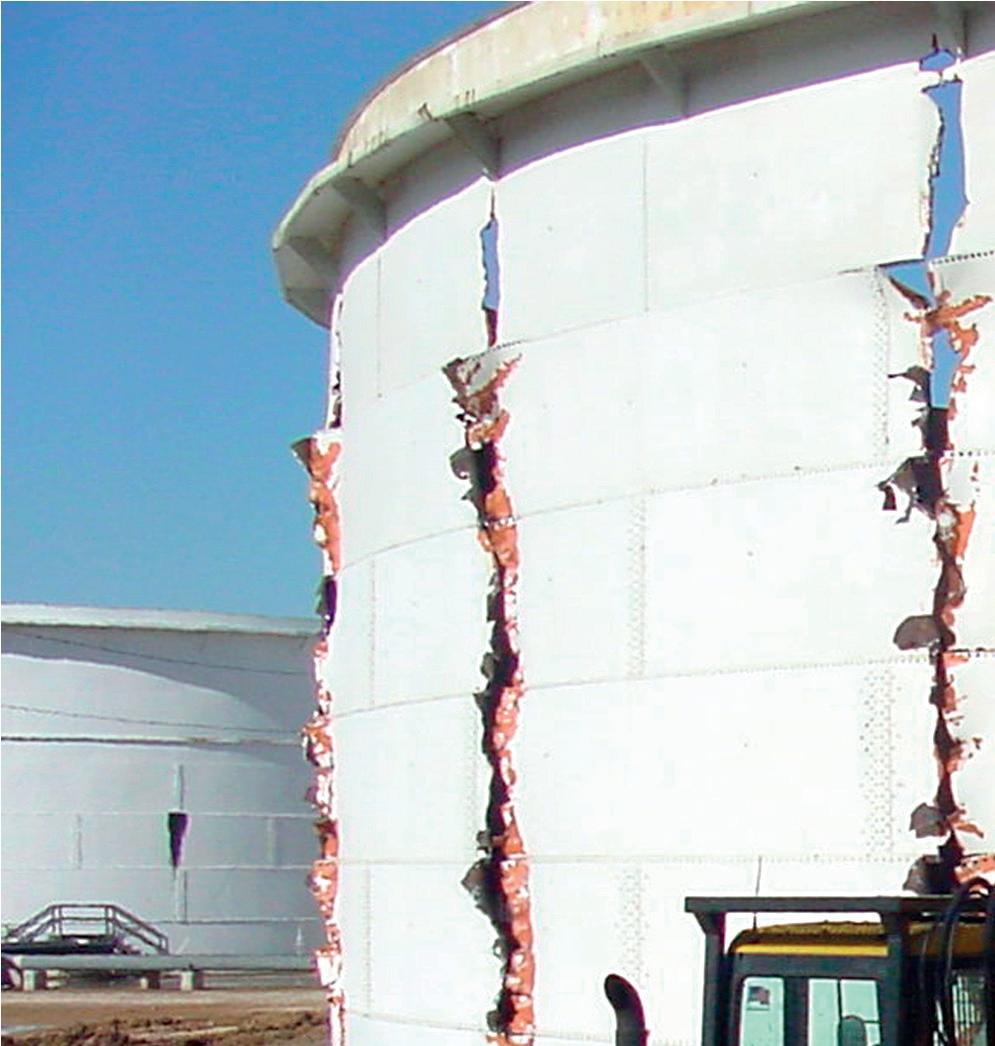
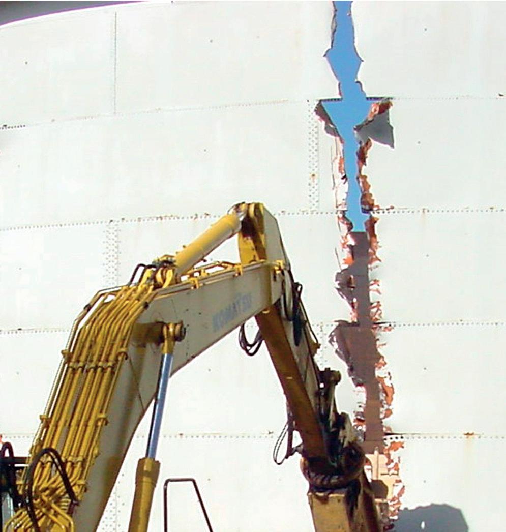
Crude oil (or petroleum) is one of the hardest materials that can be found in a tank. It is made of a mixture of hydrocarbons that varies depending on the place where the oil is found. The composition of crude oil, in fact, varies with the geographical location, age, and the depth of the well. Most of the hydrocarbons are paraffins, naphthene, aromatics, nitrogen, oxygen, metals, sulfur, asphaltic. The concentration of sulfur or oxygen can cause corrosion during the refining process and the quantity of sulfur, for example, determines if the petroleum is labelled as ‘sweet crude’ (<0.5% of sulfurs) or ‘sour crude’ (>0.5% of sulfurs). Depending on other elements, crude oil can be light, medium, heavy and extra heavy; if the API gravity of crude oil is greater than 10, it is lighter and floats on water; if API gravity is less than 10 then it is heavier than water and sinks. This case study reports the use of robots to de-sludge an external floating roof crude oil tank. Due to the corrosion of the roof’s
Figure 1. Tanks inside an industrial plant. Figure 2. Explosion proof control unit for robots.We
You strengthen your plant’s safety, productivity and availability with innovations and resources.

Endress+Hauser helps you to improve your processes:
• With the largest portfolio of safety instruments that comply with international regulations
• With applied technologies and people who have extensive industry application know-how
• With access to accurate and traceable information
Do you want to learn more?
www.endress.com/oil-gas
legs, caused by the concentration of sulfur and oxygen, the roof around the centre collapsed. Only 65% of the tank interior remained accessible. The use of a robot was the only option to clean the tank without man-entry, thereby eliminating risks that can occur to workers, along with any costs associated with man-entry.
Over time, oil storage tanks can accumulate sludge, which can compromise the integrity of the tank’s structure, capacity and the quality of the stored oil. Therefore, periodic cleaning and maintenance are essential to ensure safe and efficient operation. This case study focuses on the cleaning of a tank, which had accumulated 500 m3 of sludge.
The traditional method of cleaning an oil storage tank is through manual cleaning, which involves personnel entering the tank and manually removing the sludge. However, manual cleaning is a time-consuming and hazardous process, as workers are exposed to toxic fumes and the risk of accidents. Therefore, an alternative approach was used.
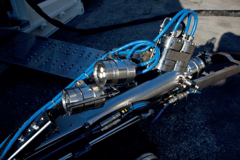
Robotic cleaning involves using remotely operated machines to clean the inside of the tank, thereby eliminating the need for workers to enter the tank. The robotic system combined the use of a suction pump or truck to remove the sludge from the tank’s walls and floor. The entire operation was completed with the final cleaning using a high pressure waterjet by the robot. The sludge was then pumped out of the tank and disposed of safely. In this case, the robotic cleaning method was used entirely to de-sludge and clean the tank. An ATEX Zone zero, IECEx or UL robot was able to enter a tank from the side manhole of 600 mm or about 24 in. The machine was equipped with bronze auger to avoid sparks that come with varied high-pressure nozzles to liquify the material if needed, but with decreased water consumption. The LED lights and cameras provided a clear view of the operation inside the tank, letting the operators remain in safe area outside the tank. It is fully hydraulic and remote controlled by a skid-mounted control unit. The robot was then connected to a vacuum truck by a suction hose (4 in.).
The tank cleaning process involved two stages: de-sludging and hydro jetting. De-sludging is the process of removing the accumulated sludge from the tank, while hydro jetting is the process of cleaning the tank’s walls and floor, so as to achieve gas-free status. The de-sludging process took 33 days, during
which time the accumulated sludge was pumped out of the tank using vacuum trucks. Once the tank was empty, the hydro jetting process began. The hydro jetting process took 27 days, during which the robotic system was used to clean the tank’s walls and floor thoroughly. The primary challenge encountered during the cleaning process was the corrosion damage to the tank’s roof top and roof legs. The corrosion damage was extensive, and there was a risk of the tank’s roof collapsing during the cleaning process. Therefore, additional measures were taken to avoid any collision of the robot with the internal structures such as roof legs.
The robotic cleaning method proved to be highly effective in cleaning the tank. The process was completed in 60 days, which was significantly faster than the traditional manual cleaning method. Furthermore, the robotic system eliminated the need for personnel to enter the tank, thus reducing the risk of accidents and exposure to toxic fumes. Finally, the cleaning process removed all the accumulated sludge from the tank and restored its structural integrity.
Oil storage tank cleaning is a crucial process in the oil and gas industry, and it must be carried out periodically to ensure safe and efficient operation. The traditional method of manual cleaning is hazardous and time-consuming, and an alternative approach, such as robotic cleaning, is safer. The robotic cleaning method eliminated the need for personnel to enter the tank, reduced the risk of accidents and exposure to toxic fumes, and restored the tank’s structural integrity.
Future robotic tank cleaning scenarios envisage more and more devices and sensors being mounted on the machine. The single robot, therefore, if initially conceived only with sludge removal functions, could in the near future provide other functions such as inclinometers, gas detectors, and thickness gauges for measuring surface damage. Increasingly, the single robot will centralise more functions that have been implemented by other instruments (leak detection, video inspection, etc.). Similar to what has happened in consumer technology where several functions (camera, audio, video, etc.) have been incorporated in a single device, and given the increasingly frequent osmosis between technological trends, it is conceivable that contractors and asset owners will have developed robots where the software and electronic components (PLCs, sensors, etc.) will play an increasingly predominant role. In this context, ATEX, IECEx and UL certifications become a guarantee that each manufacturer, in developing its technologies, remains faithful to the objective of zeroing out explosion risk factors inside refineries and industrial plants.
1. https://www.offshore-technology.com/data-insights/global-top-tenactive-oil-refineries/ (consulted on 15 January 2024).
2. https://fetsa.eu/publications/ (consulted on 15 January 2024).
3. NWANKWO,
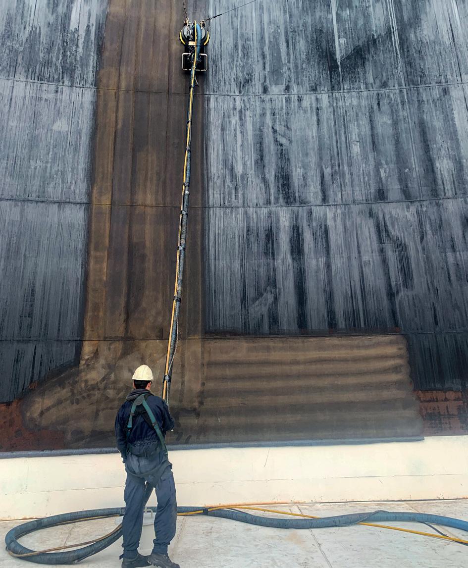
C. D., AREWA, A. O., THEOPHILUS, S. C., and ESENOWO, V. N., ‘Analysis of accidents caused by human factors in the oil and gas industry using the HFACS-OGI framework’, International Journal of Occupational Safety and Ergonomics, 28:3, pp. 1642 - 1654, (2022). 4. SKALLE, P., AAMODT, A., and LAUMANN, K., ‘Integrating human related errors with technical errors to determine causes behind offshore accidents’, Saf Sci. 2014;63:179 – 190.Industrial tank cleaning has long been a challenging and hazardous task. Using traditional methods based on manned confined space entry (CSE), workers face numerous risks, from exposure to toxic chemicals to flammable and oxygen-deficient atmospheres. However, with the advent of robotic tank cleaning, the oil industry has witnessed a significant improvement in risk mitigation and consequent safety performance. This technology not only reduces the human element in hazardous environments but also enhances the efficiency and precision of the cleaning process.
In the context of cleaning the internals of atmospheric storage tanks, robots are available today that comply with the most rigorous ATEX Zone 0, Class1 Div1 electrical safety standards. These can be used in storage tanks containing a

wide range of raw materials and products. They are designed to effectively remove even viscous materials such as heavy fuel oil. They benefit from rapid set-up on site and require no modification to either the tank wall or roof to provide entry points, utilising standard 24 in., 600 mm manways. They can be fully submerged in oil, with cameras and lights on arms which rise above the liquid level where necessary. Controlled from a portable control room located outside the tank, the robots, or more accurately remotely operated vehicles (ROVs), are propelled via a variety of different track designs, powered via hydraulic systems. Different track designs allow lined tank floors to be accommodated. The robots utilise low voltage cameras and lights to allow remote operators to precisely position them within the tank. They suck liquids and sludges via one of a range of suction heads connected via a 4 in. or 6 in. hose to a suction tanker outside the tank. Stubborn sludges are removed with the addition of gas oil
cutting fluids, high pressure water or steam, which is separated from the original tank contents once they have been removed from the tank.
However robots, like any piece of machinery, can fail. It would be wrong to pretend that this cannot happen. When subject to arduous duties, components will wear and problems can develop. Whilst routine maintenance is designed to avoid this happening, the reality is that failure can and does happen. Although frustrating, it only means that the robot stops working. The operator then has time to evaluate the situation, find the fault and recover the robot. In comparison, when a problem develops during a CSE, rescue from a poorly lit, large storage tank, 1 m deep in sludge when the injured party is 30 m from a 600 mm exit hatch and cannot potentially help themselves to escape, is a whole different story. The consequences of such a problem are worlds apart.
One of the most immediate advantages of employing robotic tank cleaning systems is the significant reduction in human exposure to hazardous environments. Traditional tank cleaning methods often require workers to enter confined spaces, exposing them to potentially harmful chemicals, fumes and oxygen-deficient atmospheres. Robotic systems, on the other hand, can navigate such environments with ease, ensuring that human workers remain at a safe distance, isolated from the hazard. Adopting a man-less tank cleaning philosophy can

represent a step change in risk reduction for an operating organisation.
CSE involves working in spaces with limited access and egress and these spaces are often poorly ventilated and contain harmful substances. Robotic tank cleaning removes much of the need for workers to physically enter these spaces, thus mitigating the associated risks of accidents, injuries, and exposure to toxic substances.
Conventional CSE, if it is to be carried out safely, relies heavily on the use of personal protective equipment (PPE). Operators of high hazard plants are all too aware of the difficulties of ensuring full compliance with PPE requirements. PPE may not be worn as the manufacturer intended, it may be of the wrong specification or it may have become defective during use. Breathing apparatus can become hot and uncomfortable and rapidly lead to fatigue. Safe usage requires constant and vigilant monitoring by trained personnel.
Operating procedures are also a cornerstone of traditional approaches to CSE tank cleaning. Ensuring that all the working parts of a complex procedure come together in a timely manner is a challenging task. Such procedures often consist of 50 – 60 pages of close-written corporate memory regarding ways to avoid incidents that have happened previously on that site, in that company or within the industry. They rely on the effective coordination of the inputs of multiple different personnel from both the operating and contracting companies, together with thorough training and effective communication. Operators regularly learn that their permit to work procedures can and do fail in a myriad of different ways, across the full range of tasks routinely carried out in refineries and terminals. During a confined space entry, sadly, such failures of permit procedures rarely have minor consequences. Robotic technology prevents the need for such processes as part of the removal of sludge from tanks.
Incidents occurring during confined space entries may be classified as ‘process safety’ events, characterised as they are by the fact that the hazards are present largely because of the nature of solids and fluids being handled and, importantly, by their low frequency, high consequence nature. Because such events, thankfully, only occur infrequently, it can be difficult for operating companies to assess how effectively their systems mitigate such risks. As a result, it can be a surprise to management when an incident occurs, as patterns in the company statistics or key performance indicators (KPIs) regarding CSE incidents may not have been detected.
It may be that instead of managers asking, “Do we see incidents related to CSE entries?”, to which the answer may well be, “Not in the recent past”, companies should be asking, “Do we see problems with either PPE compliance or permit procedures?” For most operating sites, the answer to the latter would be, “Yes”. They might then go on to ask, “If that is the case and such relatively frequent problems were to arise in the context of a CSE, would the results be considerably more hazardous?” To that question, the answer would also likely be, “Yes”. Such a discussion might prompt an evaluation of the viability of the traditional approach.
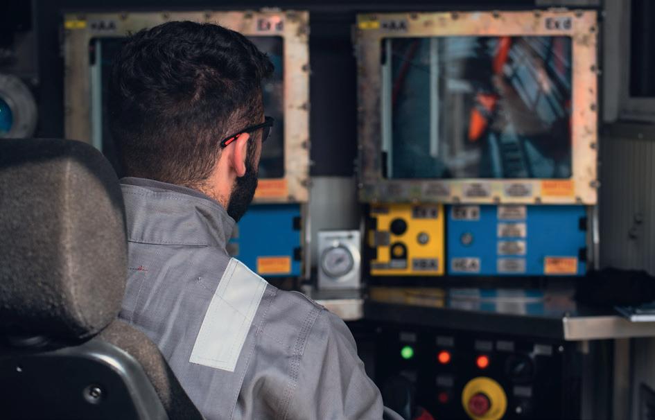
Figure 2. Robotic operative completing daily safety checks prior to deployment.
The conclusion might be that a site, with an operating history without any confined space incidents for 10 years, could well be working on borrowed time and not be aware of it.
Traditional tank cleaning methods often involve physical exertion and repetitive activities, leading to potential musculoskeletal injuries. Robotic systems eliminate this occupational hazard, as they are designed to carry out tasks with precision and consistency, without the risk of physical strain or fatigue.
Robots are not susceptible to the weaknesses of pre-existing medical conditions, ill-health, twisted joints, pulled muscles or fatigue. Health monitoring regimes can be reduced as exposure of workers to toxic materials is decreased and the long-term liability of employers is therefore also reduced. A typical 50 m, 165 in. dia. crude oil tank might involve up to 5000 man hours of exposure to CSE hazards when carried out in the traditional fashion. This can be avoided with the use of robotic technology.
Robotic tank cleaning systems are also designed to minimise environmental impact. They utilise less water and cutter stock than other processes, such as water jetting or the employment of water cannons, thereby reducing the burden on waste treatment systems. This both facilitates compliance with environmental regulations and leads to reduced waste
declarations, and therefore improves sustainability performance. This not only contributes to a safer work environment but also supports the achievement of sustainability targets.
Robotic tank cleaning systems are equipped with advanced sensors and imaging technologies that allow them to precisely navigate and clean tanks. Modern robotic technology utilises a range of different suction heads, designed to reach under, over and round internal heating coils, roof drains, and other internal tank furniture. This facilitates access to challenging areas and ensures a thorough cleaning process. This level of precision not only results in a higher quality of cleaning but also reduces the likelihood of contaminants being left behind, which could lead to potential safety hazards in the future.
Robotic tank cleaning has emerged as a turning point in industrial cleaning processes, revolutionising safety standards in hazardous environments. By reducing human exposure to risks, limiting the need for CSE, and enhancing cleaning precision and efficiency, this technology not only protects workers but also improves the quality and sustainability of industrial operations. As industries continue to adopt and advance these technologies, even greater strides in safety and efficiency can be expected in the years to come.


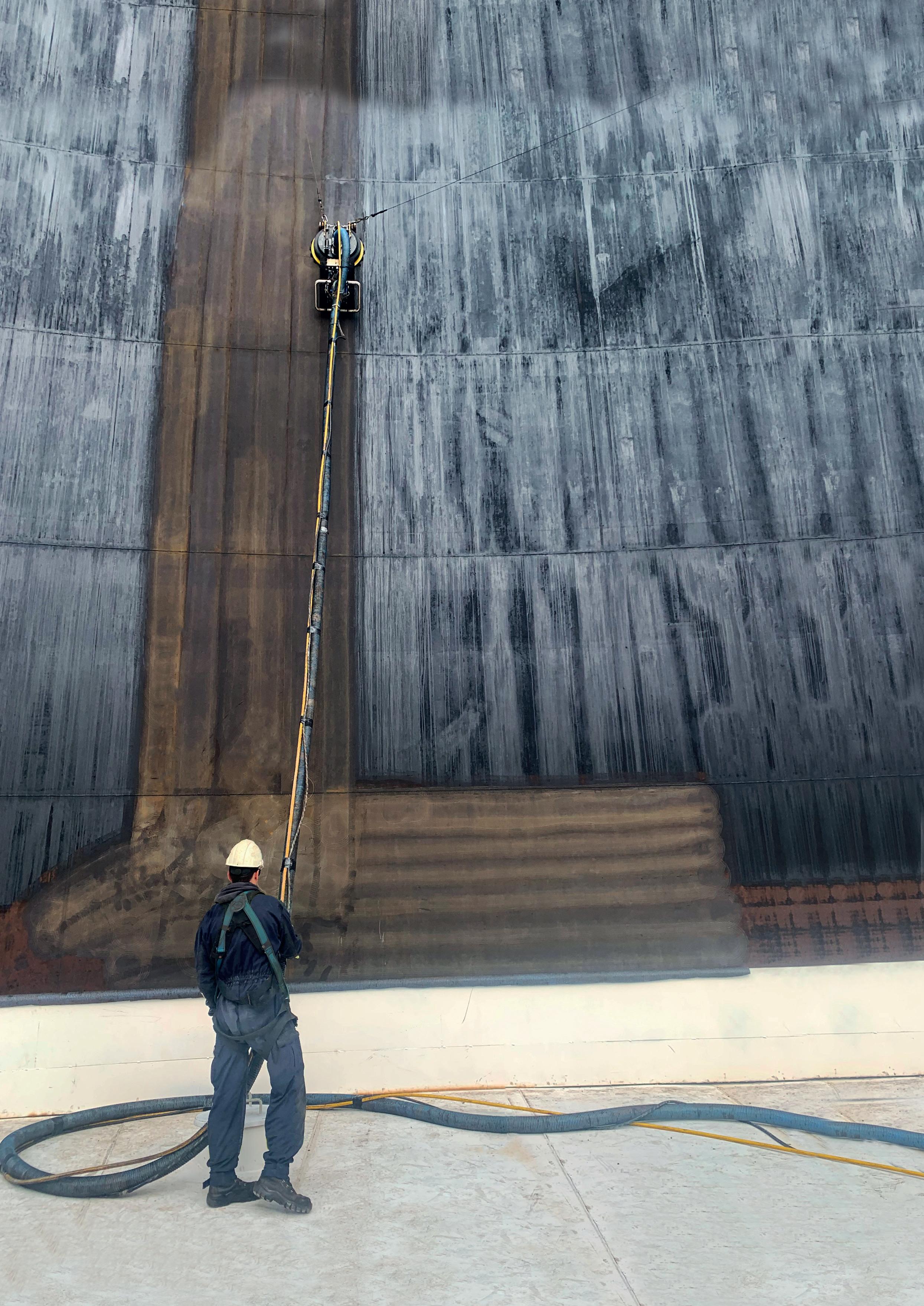
Jordan Koster, Jetstream of Houston LLP, describes the benefits and potential applications of implementing automated tank cleaning systems.
With the growth of artificial intelligence and rapidly increasing technological capabilities, it is natural that contractors seek automated solutions to enhance safety and improve efficiency. As such, the industrial cleaning industry is ready to benefit from new automated solutions. Waterblasting has been a go-to method for decades for applications ranging from cleaning oil and gas storage tanks to removing paint from large surfaces. While using high-pressure water for surface cleaning is not a new concept, the introduction of automated methods is revolutionising the industrial cleaning industry and offering a safer and more efficient alternative to handheld waterblasting tools. The first step to selecting an automated system is understanding the benefits that it can bring to an industrial cleaning business. Subsequently, two main factors must be evaluated.
Traditional methods of cleaning oil or gas storage tanks require an expensive investment in scaffolding, up to four crews and at least four water blasting units. Crews must climb the scaffolding with a waterblasting gun in hand and spend hours directing up to 40 000 psi of high-pressure water at close range. They must try to thoroughly clean every square inch of the tank’s surface, but often miss spots or fail to adequately clean due to the high degree of precision the job requires. The work is also physically exhausting and dangerous, calling for regular breaks to reduce fatigue.
While there will always be a time and place for this method, new automated robotic carrier systems are revolutionising tank and other industrial cleaning applications. Automated carriers are programmed to move in a specific pattern across the entire surface so that operators can complete a thorough cleaning without any missed areas or unnecessary overlap, ensuring an efficient process. These robotic carriers attach to a tank’s wall with magnets, allowing operators to remain safely at ground level while operating the robot through a remote control, virtually eliminating the cost of scaffolding systems.
Some systems feature four-wheel drive and a wide range of motion both up and down and side to side and even the ability to drive upside down, allowing the cleaning of nearly any magnetic surface. The carriers are connected through an umbilical line to a control panel where an operator controls the robot from up to 100 ft away, significantly reducing the risk of injury from
high-pressure water and hoses. Fall-protection lines secure the robot for safety. Some manufacturers’ units are even ATEX approved for Zone 2. This European standard indicates that the automated system is designed for safe operation in oil and gas tanks for petrochemical applications.
Whether ensuring a storage tank is ready for an inspection or a product switch for a new rental agreement or removing old paint to prepare for a new coating, completing the work both safely and efficiently is paramount. While traditional, manual methods may get the job done at the end of the day or a few days they sacrifice efficiency. Automated waterblasting systems do not require regular work breaks, safety protocol reminders or training on how to implement best practices. To put it simply, the automated systems ensure continual operation and faster completion for these projects.
Many contractors find that for a cost similar to or sometimes less than scaffolding setup, two robots cut other costs in half. Automated carriers require half the number of waterblasting units and half the number of nozzles. Four crews become four operators one for each robot and pump. Additionally, a smaller crew size and enhanced safety reduces the risk of workers compensation claims.
Automated waterblasting systems present clear productivity and profitability benefits in tank cleaning as well as other industries, achieving removal and cleaning rates of up to 40 m2/h for paint removal jobs. This creates significant opportunity in an industry like surface preparation where contractors are often paid per square meter.
To fully realise the benefits of an automated approach to cleaning, it is important to integrate the robotic carrier into a cohesive system that will maximise the overall efficiency of the job. This includes the pump, connections, nozzles, safety gear and for some applications a vacuum system.
Open waterblasting systems use a swing arm and do not include a vacuum system. This provides benefits in terms of speed and efficiency. This method is cost-effective because it does not require a vacuum pump and truck.
Closed waterblasting with a vacuum blastcan collects all materials including the used water along with any paint, debris or other hazardous material. This leaves behind a completely clean and dry surface and surroundings, which combats rust and allows for immediate resurfacing. Closed waterblasting also allows the hazardous material to be collected and properly disposed. Some operations even treat the water to allow safe disposal on site. Closed systems also remove vapour from the air, which improves visibility, especially when operating in an enclosed area such as a storage tank. If considering this option, it is important to find a manufacturer who can offer all aspects for the closed waterblasting system from the robot to the vacuum, to the pump.
While the new technology of an automated system might receive all the attention, the fact remains that with any waterblasting system, the pump is the heart of productivity. The efficiency of an automated system means little without a pump system that minimises downtime and paces the robotic carrier in efficiency.
The key to finding the right pump begins with identifying the correct size for the application. Many tank cleaning applications require a flow of approximately 10 gal./min at roughly 40 000 psi. A 325 hp pump rated for 12 gal./min is often the best fit for these jobs, although some contractors
Figure 1. Automated robotic waterblasting carriers are programmed to move in a specific pattern across the entire surface so operators can complete a thorough cleaning without any missed areas or unnecessary overlap.
lubrication for oil do not contain an oil pump that can fail and cause a loss in oil circulation. Additionally, pumps that feature oversized roller and journal bearings and a forged crankshaft tend to have a long lifespan and maintenance intervals as long as 500 hours. Valves are usually the most frequent wear item on waterblasting pumps, so opting for a cutting-edge pump that enables valve change outs in the field in five minutes or less has a huge impact on productivity. Additionally, considerations should include easy access to internal components and no special tool requirements.
Waterblasting safety does not end where the water flows. Like the carriers they power, waterblast pumps should support safety on the jobsite. Consider pumps that feature a locking rod box that protects the operator from moving parts and high-pressure water while also providing ease of service.
choose pumps with higher flow capabilities, depending on the scope of their operation. For maximum versatility, contractors should consider a pump that features interchangeable fluid ends. With this technology, crews can quickly and easily convert the pump to different operating pressures to match a full range of jobs.
While maintenance is unavoidable, operations benefit from pumps that allow streamlined servicing with a simple design and a minimal number of parts. Those that use splash


Automated systems continue to create new opportunities for contractors to improve their efficiency and productivity, boosting the bottom line. Contractors should work with a trusted manufacturer to ensure all components of their waterblasting system are optimised to create a safe and effective solution that will make fast work of any surface cleaning job. The manufacturer should also offer training for proper equipment operation and to provide knowledge of industry safety standards. With the right combination of equipment and resources, automated waterblasting systems are ready to take industrial cleaning operations to the next level.


home for the latest
Dr Megan Pearl, Locus Bio-Energy, analyses the challenges present when cleaning storage tanks, and discusses the benefits offered by biosurfactant-based cleaners.

Each day, nearly 100 million bbl of oil are transported and stored through pipelines, tankers, trucks, railcars and terminals, leaving behind viscous layers of sludge – comprising heavy hydrocarbon-based substances like asphaltenes, paraffin and other organic deposits. Cleaning the substantial volumes of waste poses a formidable set of challenges that have long hindered operational efficiency and profitability in the midstream sector. However, crude oil is not the only material accumulating waste. In 2021, a staggering 130 million gal. of friction reducer was used, with 77 million gal. deployed in the US Permian region alone. The popularity of emulsion friction reducers for hydraulic fracturing exacerbates the cleaning challenges in thousands of railcars, road tankers and storage tanks each year.
Traditional methods to handle the massive waste accumulation face four main challenges: toxicity concerns, costly specialised equipment, slow processes leading to prolonged shutdowns, and the added expense of disposing sludge contaminated with cleaning solvents.
The use of standard midstream cleaning solvents has introduced a critical concern for potential toxicity. Many of these solvents contain hazardous components such as xylene and heavy aromatic naphtha. They pose a significant risk to the health and safety of workers when deployed in the confined spaces of storage tanks and terminals. Exposure to toxic fumes and chemicals during cleaning operations is a serious occupational hazard that demands urgent attention.
Traditional midstream cleaning methods often necessitate the use of specialised equipment and extensive manual labour. The requirement for costly machinery tailored to handle the specific challenges of
cleaning substances like friction reducer and sludge has contributed significantly to the overall maintenance cost. Moreover, the manual cleaning efforts involved are time-consuming, labour-intensive and require skilled personnel, further compounding operational expenses.
Solvents commonly deployed in traditional midstream cleaning processes exhibit a slow and gradual action, resulting in extended shutdowns that can span days or even weeks. During these prolonged periods of inactivity, vessels remain out of service, leading to financial losses and reduced profitability. The impact is not only felt in terms of direct operational costs but also in the missed revenue during downtime. As the industry strives for increased efficiency, minimising these shutdown periods has become a crucial objective.
Disposal of removed waste has introduced an additional layer of complexity and expense. Sludge contamination with the cleaning solvents used in the process requires careful handling and disposal, often involving specialised waste management procedures. Additionally, current cleaning methods for residual friction reducers utilise high volumes of water. Although water itself is inexpensive, the polymer-contaminated wastewater must often be trucked offsite – sometimes across state lines – for proper disposal. These added disposal costs further contribute to the overall financial burden of traditional cleaning methods. Therefore addressing this challenge involves not only finding effective cleaning solutions, but also implementing environmentally sustainable practices for waste disposal.
With increased oil and gas demand, the need becomes more urgent for a transformative solution that is not just faster and more effective but also safer. Midstream companies have navigated these obstacles using numerous methods with varying success. Some solutions address specific issues but exacerbate others or offer only temporary relief. Today’s dynamic market also places greater emphasis on increasing profitability in as many areas of operation as possible. This has driven forward-thinking operators to evaluate each stage of the cleaning process from start to finish. Rather than adopting piecemeal fixes that merely address immediate concerns, industry leaders are increasingly exploring innovative technologies that offer comprehensive solutions.
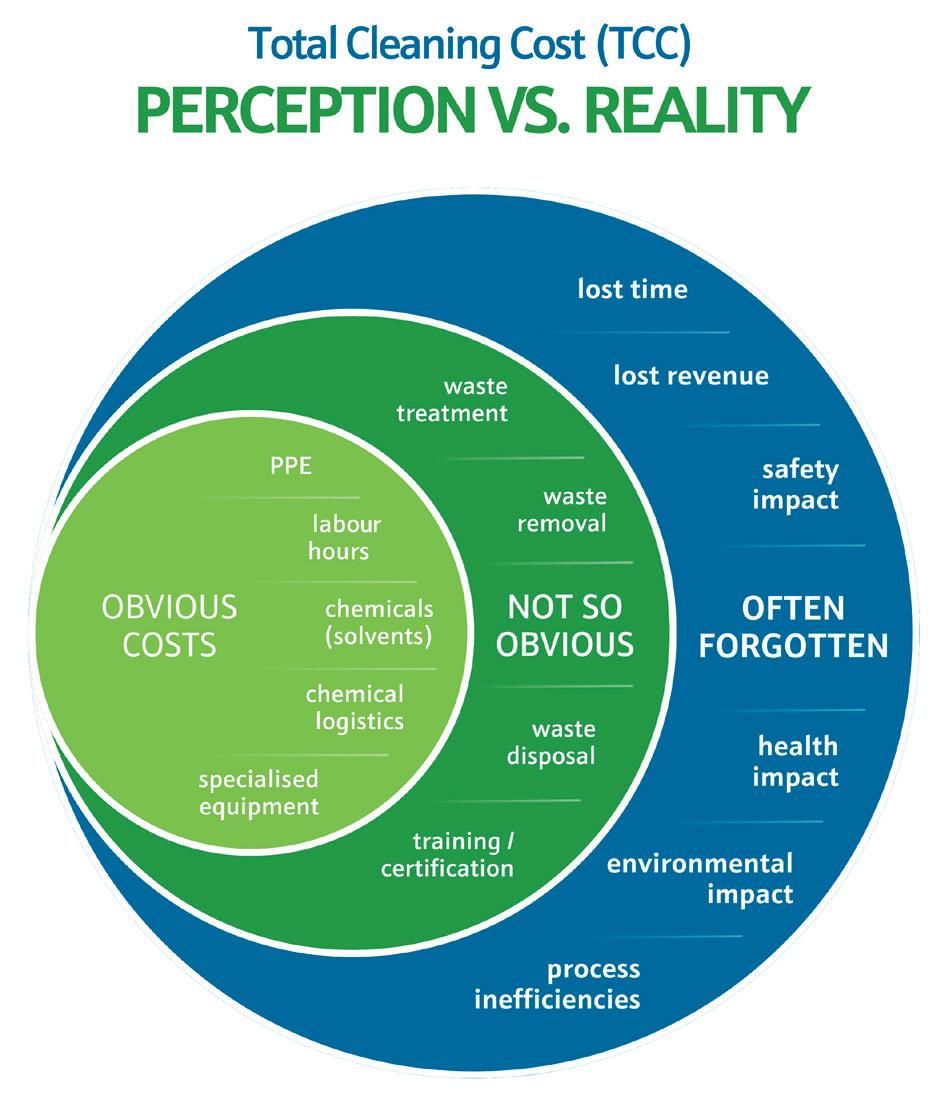
To holistically assess the total cleaning cost (TCC), it is important to consider the breakdown of expenses in a conventional barge cleaning process.
Chemicals (typically solvents) and their logistics for transport to the cleaning site present obvious direct costs. Heating trucks and associated equipment, which are required to maintain optimal cleaning temperatures, also add to tangible costs. Traditional cleaning methods, such as manually removing substances from the barge bottom, contribute significantly to TCC through the quantity of personnel, man hours, and personal protective equipment (PPE).
The resources and time needed to remove and/or treat waste generated from cleaning add to indirect costs, often varying by area due to regional environmental regulations. Another often underestimated cost is the downtime incurred during the cleaning process. The longer a barge is out of commission, the greater the revenue loss for the company. It is imperative for companies to consider the financial impact of downtime, especially the potential revenue generation lost during the inactive period.
Furthermore, what is the cost placed on employee safety? Though intangible (outside of PPE expenses), the prolonged use of and exposure to toxic chemicals in confined spaces poses significant risks to employee health and safety. As companies increasingly evaluate cleaning processes, it becomes more apparent that TCC involves much more than labour and chemicals.
Beyond the immediate expenses, exploring opportunities for additional profit, such as the sale of residual oil, adds a nuanced dimension to the financial analysis.
In response to these pressing challenges, a new technology has emerged – biosurfactant-based cleaners. These cleaners offer efficiency and sustainability benefits, as well as potential revenue. In 2023, biosurfactant-based AssurClean was a finalist for ‘best advancement in maintenance technology’ for the midstream sector. The designation was based on its ability to reduce cleaning time by 50% for tanks, pipelines, barges and more, while also turning waste oil and sludge into profit.
Conventional cleaning chemicals are typically sourced from non-renewable, petroleum-based materials. However, research and production are rising for bio-based surfactants, which range from being partly or wholly derived from biological sources. Biosurfactants are a premium subset of bio-based surfactants that are 100% derived from renewable raw materials. They are increasingly proving to be sustainable, renewable and, most importantly, effective.
Typically used solvents often work slowly, gradually dissolving downwards from the surface. In contrast, biosurfactants feature complex molecular structures with multiple active sites and multifunctional properties. The nanometre size also contributes to the ‘biosurfactant trifecta’, which is the ability to penetrate, disperse and suspend during the cleaning process. The powerful functions work synergistically to tackle cleaning operations from multiple angles through:
n Penetration for deeper reach within the layers of waste accumulation.
n Dispersion to break contaminants down into smaller, manageable components.
n Suspension to prevent reattachment of these components to surfaces.
This three-pronged approach not only enhances the efficiency of cleaning but also enables the technology to attack contaminants from the inside out, ensuring a thorough and effective cleaning process that goes beyond surface-level treatment.
Biosurfactants possess unique properties that disperse and enhance the flowability of oily wax, asphaltenes, friction reducers and solids. The higher potency allows for smaller, low-cost doses, making them very effective. Using a

biosurfactant-based product also reduces the amount of water needed for cleaning, leading to reduced waste disposal costs for contaminated water. What sets biosurfactants apart is the ability to achieve these cleaning results without requiring specially designed equipment or labour-intensive manual cleaning efforts, as well as the potential to turn waste into profit. The biosurfactant-based product can be used as a standalone treatment or added in small amounts to acid and steam, significantly enhancing treatment efficiency while also reducing the required dosage.
In one case, the biosurfactant-based cleaning product effectively removed 4 ft of sludge from a 40 000 bbl storage tank without the use of any hydrovac trucks. Although the tank was previously deemed unusable and had been idle for years, the remediation process turned it into a profitable asset.
For the treatment, one drum of the biosurfactant-based product was diluted at a ratio of approximately 10:1 and added to the tank. The tank underwent a 72-hour soaking period, during which no agitation, circulation or heat was applied. Approximately 1000 gal. of crude oil sludge was liquified after the soak period. In addition to the significant reduction in downtime, the operator recovered nearly 2000 bbl of sellable oil after separating the solids.
AssurClean was also used to remove residual friction reducer from a storage vessel in under two hours with minimal water usage and light agitation. Traditional methods typically require several hundred gallons of water, involve multiple personnel and extend over eight hours.
The process involved adding a 5 gal. bucket of the biosurfactant-based cleaner to a 330 gal. tote containing residual friction reducer. The tote was manually rocked

back and forth, then left to settle for one hour before the liquid was discharged. After a 24-hour period, the discharged liquid had fully separated into two distinct layers: AssurClean and friction reducer. Analysis of the friction reducer layer revealed nearly identical rheology and friction reduction profiles as the neat friction reducer. The resulting ability to reuse both products further demonstrates the technology’s potential to offer nearly waste-free cleaning in a cyclic, low-water process.
In the Permian basin, application of the biosurfactant-based product for barge cleaning reduced downtime from months to days, with 92% faster cleaning time and 70% lower costs. Previously, the operator used a labour-intensive process that required employees to wear respirators and manually remove solids at the bottom of the barge. The process typically spanned 3 – 4 months, incurring costs up to US$500 000 per barge. The associated downtime also resulted in a significant loss of revenue.
Using the biosurfactant-based product enabled liquefaction of the solids, replacing labour-intensive manpower with safer, more efficient vacuum cleaning methods. Further, it reduced downtime to just 7 – 10 days, with costs totalling about US$150 000 per barge. The operator was able to return the barge to operational service faster, with the added opportunity for revenue
from selling the residual oil that was removed during the cleaning process.
As global energy demands continue to rise, so will production operations and the adoption of new technologies to supply more oil. The corresponding rise in midstream activity (and associated storage and transport) has made the need for more efficient cleaning methods more apparent. Some operators are shifting their focus beyond tangible expenses to holistically evaluate their processes for a more accurate total cleaning cost.
One significant discovery surfacing from these comprehensive reviews is that inefficiencies in indirect costs, such as waste management, can often surpass direct costs. For example, cleaning a residual friction reducer from a tank can require hundreds of gallons of water, generating more waste than the initial amount that required removal.
Modern solutions such as Locus Bio-Energy’s biosurfactant-based solutions are increasingly being used to address key pain points across all levels of oil and gas operations, including tank and terminal cleaning. Biosurfactant technology offers a cost-effective and efficient alternative to traditional cleaning methods, providing a path to a new era of cleanliness, safety and profitability in the midstream sector.

Supply chains are increasingly becoming the focus of companies’ process improvements. There are both qualitative and quantitative reasons for this. On the one hand, people expect companies to ensure the quality aspect along their supply chain. On the other hand, the quantity aspect must be ensured when a product is passed on from one company to another.
The first step in improving the supply chain is to have continuous, highly accurate level measurement. The automatic tank gauge (ATG) measures continuously and custody-transfer based procedures warrant high accuracy.

The continuous measurement is an essential advantage against manual sounding at certain points of time, which provides data when staff access to the tanks is not possible due to adverse weather conditions. In addition, automatic measurement avoids potential human error.
Aside from accuracy and reduced error rate, the initial investment for a gauge pays off quickly: the actual savings can be easily calculated per tank farm based on how often and how long it takes to perform a manual measurement as well as the labour cost involved. An example of this could be how a daily manual sounding on eight tanks (30 minutes per tank with an hourly cost of US$50) amounts to US$200. Multiplied by 200 working days per year, this comes to an estimated annual cost of US$40 000.
The investment in a high-precision level gauge at a refinery usually amortises in about 14 months. Other benefits include the automatic generation of reports per shift or per loading, which eliminates the possibility of manual human error.
To account for business-to-business transactions or determine taxes (for custody transfer) in the supply chain, companies must ‘follow the product’ to verify wherever it arrives (e.g. trucks, trains or barges) and is unloaded into tanks, and where liquids are loaded into trucks, barges or ships, using flow meters and manual measurements.
By ‘following the data’, the supply chain is optimised and more accurate information is generated. This is required at multiple points, including:
n When the product is loaded, information on volume/mass, temperature, and density is useful for the recipient before the product arrives.
n When the product is unloaded, it is useful for the shipper of the product to know the actual loaded volume/mass to see what has arrived.
n If the shipper, owner of the product, transportation company, and recipient of the product are independent companies, the data increases transparency for all parties involved in the supply chain.
For instance, a marketing distribution terminal receives product from a refinery that has sold certain quantities to
individual oil companies. The terminal stores the product and loads it onto trucks for the individual oil companies, which have them delivered to their filling stations. Multiple parties buy, sell, and own the same physical product, but their share of each link in the supply chain must be clearly identified so that the correct amounts can be invoiced later.
All financial transactions, such as the payment of a delivery or the payment of import duties, cannot be based on the fill level, but on the precise calculation of volume or mass.
The calculation of volume from level is done by strapping Tank Capacity Tables (TCT) or by interpolation. In addition, some corrections are made to compensate for thermal or other effects. The main influencing factor is the change in product temperature: a change of 1˚C affects the volume by 0.1 %. This may not sound like much, but for tanks with a capacity of more than 10 million l or large crude oil transporters, this change corresponds to the size of several trucks worth thousands of euros.
There are two methods for determining the transfer quantities sent and received: either relying on flow meters or level-based determination of volume or mass differences in tanks.
A crucial factor to be considered are deviations that must be considered normal due to inaccuracies. Regardless of a flow or level-based measurement, there will always be differences. The inaccuracy calculations of flow and level measurements are very different and therefore allow different perspectives on a transfer:
n Flow measurement has a certain inaccuracy of 0.xxx%, calculated on the total amount of product transferred: 0.05% for 1000 l or 0.05% for 1 million l, the amount refers to the total amount transferred.
n The level measurement accounts for a fixed inaccuracy, e.g. +/- 1 mm for a 5 m tank or for a 30 m tank; the volume, which represents the inaccuracy, is always the same (provided the tank diameter is the same).
Monitoring a transfer via flow meters or level gauges are different views of the same product transfer. This can help to find weak points in the supply chain.
For example, at a biodiesel refinery that used to supply its neighbouring plant via an internal pipeline, billing was carried out via flow meters. But at present the refinery sells its diesel to external companies that transport it by barge. If the buyer insists on using the barge’s flow meters, then the refinery has no way to verify correct charges when old and unreliable level meters on the tank do not allow the biodiesel refinery to verify the quantities transferred. Custody transfer level gauges and an approved tank gauging system are an easy-to-implement way to verify the barge’s flow meters.
It is the collection of data over longer periods of time that gives information about the supply chain. This knowledge can then be used to improve processes at both source and destination.
Business process consulting is the first step in analysing the supply chain to identify the points at which products are transferred, stored, and distributed. During an Installed Base Audit (IBA), each point can be evaluated, analysed, and verified as to what measurements are taking place, what type they are and how accurate they are.
Along the supply chain, the correlation of the quantities at the loading point and the unloading point is recorded. In the example of a crude oil carrier transporting bulk liquids from Saudi Arabia to Germany, there will always be a differential between how much was loaded in Saudi Arabia and how much was unloaded on arrival in Germany. Identical figures are impossible to achieve, every measurement is subject to error and there are different additional influencing factors at each transfer point.
Recording these observed volumes over a longer period of time is a first point of reference and can reveal pain points or potential for improvement, such as changes in ambient temperature. As a first step, the quality of the measurements can be improved by using more accurate measuring instruments in the event of high deviations. High deviations at certain points in the supply chain may indicate that processes are not being measured consistently and/or inaccurately or that procedures are not being followed.
Typical recommendations include the following:
n Use mass flow metering with custody transfer approved instruments for offloading ships and barges.
n Implement custody transfer approved level measurement, which is safeguarded against manipulation.
n Use multi-point temperature measurement to detect temperature stratification and correct to standard temperature.
n Match flow meter readings with delta volume from custody transfer level measurement in tanks.
n Develop or improve loading and offloading procedures by automatically monitoring them in the tank gauging software and documenting the results.
n Record all tank-to-tank transfers via the source and target levels (and respective volumes) in the tanks or consider flow metering for tank-to-tank transfers.
If these recommendations are followed, all parties involved will benefit from increased efficiency and time saving during loading and unloading, improved transparency along the supply chain, and increased safety through automatic level measurements, e.g. no manual measurements during rain or storms. Real-time monitoring of critical delivery parameters such as flow and pressure allows potential anomalies to be addressed directly, while operators and distributors can utilise the full capacity of the tank or silo. In addition, more transparency and confidence in deliveries on the buyer’s side is achieved.
Optimised logistics management is fundamental to successful stock management. Forecasting, scheduling, and replenishment management are tools to increase the efficiency of every facility.
While monitoring systems for static and dynamic measurements typically cover a local operation in real time, a globally accessible system aggregates information from multiple locations and provides insight into global operations.
Working capital reduction through reduced overall inventory levels is achieved through timely orders that are automatically scheduled based on optimised shipping points to ensure material availability as well as optimised maximum stock levels for inventory at each location and the upstream and downstream supply chain location.
Reconciliation with increased accuracy compares level measurement and calculated volumes, and creates transparency by incorporating readings from flow meters for the inflow to a tank (input) and the outflow from a tank (output) into the measurement process. The Reconciliation Report relates these three values and compares them with each other, thus making discrepancies visible.

By displaying important indicators for the inflows and outflows of the individual tanks in the form of data and diagrams, it is possible to analyse the cycle patterns of the past and use them as a basis for future planning.
The continuous automatic execution of these reconciliation tasks and the subsequent analysis of the information enables procurement departments to reduce stock levels and thus investments, optimise administrative tasks and costs through fewer human errors, reduce logistical effort, and shorten procurement times.
IJon Taylor, Rotork, provides insight into the strategies that LNG terminals can use to optimise performance and prolong lifespan through efficient flow control and effective maintenance.
n recent years, LNG has emerged as a crucial component of the global energy mix, with LNG exports experiencing exponential growth. The US alone doubled its LNG exports to Europe in 2021, underscoring the increasing relevance of LNG in addressing the rising global demand for natural gas, which is expected to grow by 10% by the end of the decade.1 As LNG plays a pivotal role in the lower-emission hydrocarbon bridge of the energy transition, it is necessary to explore the significance of efficient flow control throughout the LNG value chain, focusing on the importance of effective maintenance plans in LNG applications.
The LNG industry is poised for substantial expansion, with liquefaction capacity projected to see major growth and regasification capacity anticipated to increase significantly by 2030.2 The infrastructure needed to accommodate this growth presents challenges in many parts of the world. LNG's ability to serve as a lower-emission hydrocarbon bridge necessitates substantial investments in liquefaction, regasification, and transportation infrastructure. This infrastructure expansion emphasises the critical role of effective flow control, requiring reliable actuators and flow control solutions to ensure a smooth
operation from liquefaction and extraction to regasification, transport, and distribution.
In the cryogenic part of the LNG process, large quantities of gas are transported at extremely high pressures and controlled with actuated valves between 36 in. and 72 in. dia. It can be converted into a liquefied condition by applying pressure to the natural gas and reducing its temperature using compression trains and cryogenic systems. Valves and related equipment must withstand the extremely low temperatures involved (-162˚C).
Cryogenic valves are usually constructed from type 316 stainless steel due to its ability to maintain its strength at extremely low temperatures. To prevent potential hazardous events and prioritise operator safety, valves regulating LNG flow must adhere to stringent safety standards such as BS 6364. Actuators controlling the valves must offer safe and dependable operation in continuously hazardous conditions.
Throughout this process, the inherent risks associated with the high-pressure gas necessitate robust safety measures. Emergency shutdown systems are critical components in managing potential hazards. Recognising this vital need, LNG operators rely on well-established and reliable solutions. Since the first LNG plants were built in the 1960s, Rotork has been a partner of such sites. Its pneumatic actuation systems provide large valves with the high-speed closure capability and torque required for effective emergency shutdowns.
Rotork’s GP and CP pneumatic scotch yoke actuators are widely used in LNG terminals across the globe. Moreover, they reliably operate ball and butterfly cryogenic valves within
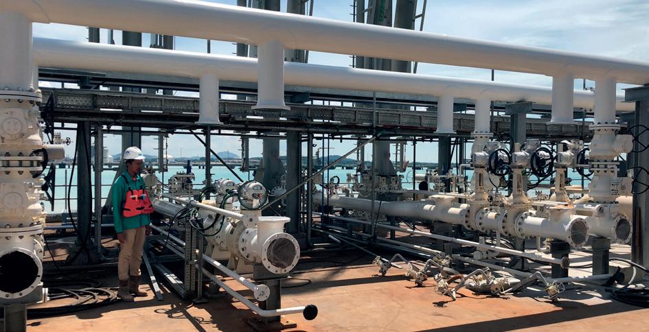
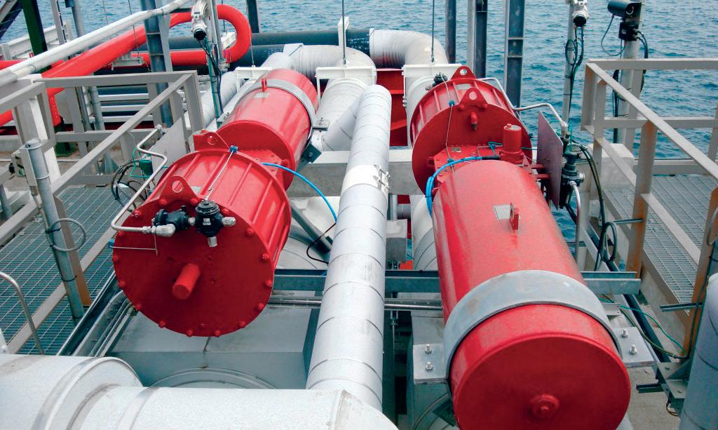
storage and regasification plants. Certified to IP 66M/67M standards and equipped with corrosion-resistant cylinders, these actuators are well-suited for the challenging environments of the LNG industry.
High standards of safety certification are paramount throughout the LNG supply chain. The Safety Integrity Level (SIL) serves as a benchmark for performance expectations in safety systems. It is integral to a comprehensive functional safety plan encompassing techniques, technologies, and procedures designed to mitigate potential hazards. Recognising the importance of a life-cycle approach in managing hazardous processes, Rotork has worked to ensure that both GP and CP actuators achieve SIL3 certification for single-device operation as per IEC 61508, demonstrating their effectiveness for handling hazardous substances.
While many valves remain open during normal operation, operators require absolute confidence in their ability to close swiftly when needed. These products can be equipped with Rotork’s PIC0 system to provide a partial stroke testing function.
Using bulk carriers is one of the most common methods to transport LNG across long distances. Actuators for process control are mounted on these specialised LNG carriers.
For example, during LNG shipping, safe, dependable, and efficient flow control management of liquefied gas into containers is reliant on intelligent electric actuators, such as Rotork’s IQ actuators. Extensive real-time and historical feedback data via data logs (such as warnings, valve torque profiles, and the quantity of valve movements/operations) is another benefit of using intelligent actuators for LNG flow management. Explosion-proof certified actuators can ensure long-term dependability even in the most challenging conditions.
Another option is electro-hydraulic actuators, which combine the mechanical spring-return or accumulator fail-safe action’s dependability with the accuracy of hydraulic control and the simplicity of electrical operation. Skilmatic SI actuators have been certified for hazardous areas and are commonly used for remotely operated shutdown valve (ROSoV) functions and ESD inputs pertaining to functional safety. For usage in these applications, they provide ESD options with single or dual inputs and partial stroke testing (PST).
Regasification often takes place at coastal import terminals, which have specific requirements for handling LNG. The functionality of the actuators is a critical component of ensuring safe and dependable operation throughout the entire LNG value chain. Actuators are a common sight at automated tank farms. They perform isolating duties for regular flow control, modulating actions, and fail-safe activity for essential safety requirements. Intelligent electric actuators are also used in tank farms for safety-related purposes, such as Emergency Shut Down (ESD), which is crucial in case of hazardous situations.
Control and monitoring centres are critical to simultaneously controlling hundreds of actuators on LNG sites. Rotork’s Master Station control system is used by LNG facilities all over the world, such as the Pengerang Deepwater Petroleum
Figure 2. Scotch yoke actuators in service at a marine terminal.Terminal in Malaysia, which contains two 200 000 m³ LNG storage tanks, a regasification facility, and berths for the loading and unloading of LNG tankers.
Utilising a field network, a Master Station can remotely manage hundreds of intelligent actuators, while the actuators regulate the flow of LNG. This technology provides dependable plant management and monitoring, which is essential in the LNG industry.
As the industry focuses on sustainability, the use of electric actuators emerges as a strategic choice to help reduce emissions. Retrofitting natural gas-powered pneumatic devices with electric actuators helps to reduce or eliminate methane and volatile organic compounds (VOC) emissions. This environmentally conscious approach contributes to a lower environmental footprint, improved regulation duty, and the increased reliability of LNG operations.
Throughout the LNG process, emissions can be reduced using electric actuators. In Belgium, Rotork upgraded an LNG terminal, a 4000 km pipeline, and an underground storage facility. Part-turn intelligent IQT actuators were installed to manage butterfly valves on boilers located in unmanned gas pressure-reducing stations. These valves are responsible for reducing the pressure of natural gas, allowing it to flow through a network that operates at a lower pressure or be transferred to an end consumer facility.
The installation of IQT actuators facilitated accurate flow control, emissions reduction, simple setup, diagnostics, and dependable operation. Rotork Site Services adapted IQTs onto existing valves at multiple locations. They offer continuous position tracking, even when there is no power available. IQTs are explosion proof in line with international standards, and are protected against water ingress (double-sealed) achieving a rating for water protection of IP66/68 at 7 m for 72 hrs.
LNG flow control equipment is used in challenging operational and environmental conditions on a daily basis. These assets often work under abrasive, extreme-temperature conditions and are subject to excessive vibration, so it is essential that they perform reliably. The efficiency of these assets depends on the maintenance they receive to ensure their availability throughout the LNG journey.
When implementing a maintenance programme, it is crucial to consider the entire life cycle of an asset. Neglecting unsupported equipment can pose significant risks. However, by utilising specialised service and maintenance programmes, sites can effectively manage potential obsolescence and ensure that the site operates at peak efficiency with minimal unplanned downtime.
Asset failure due to poor maintenance can result in reduced performance, decreased quality and productivity, loss of investment, and severe environmental consequences. A site operator’s responsibility is to ensure that the operation is running as effectively as possible to avoid unplanned downtime brought on by failing or underperforming equipment. Equipment failure can lead to catastrophic outcomes, so it is crucial to take proactive measures to prevent it.
To manage potential issues that a site could encounter, an effective and comprehensive site service programme is essential. The programme needs to be affordable, easily accessible, and adaptable enough to meet the needs of the customer.
A reliability services programme can offer different levels of coverage based on three tiers: basic, standard, and premium. Customisable programmes increase asset availability and dependability while reducing downtime. Having the option for additional upgrades to suit the demands of the user is also an advantage. Adaptability is the key to maintaining consistent enhancement of a site’s functionality.
The importance of taking into account an asset’s whole life cycle cannot be overemphasised. Ageing equipment can have a number of concerns. However, with focused service and maintenance programmes, operators may manage obsolescence and sustain a site operating at optimum performance. Poor maintenance of assets can result in reduced performance, decreased quality and productivity, loss of investment, and severe environmental consequences. Site operators need to ensure their operation is running as effectively as possible to avoid failing or underperforming equipment. If equipment fails, the results can be disastrous.
One service Rotork can offer to help is its cloud-based asset management system for intelligent actuators and valves. The Intelligent Asset Management (IAM) system can provide comprehensive condition monitoring, anomaly detection and predictive diagnostics that allow asset conditions and actionable insight to be accurately and clearly communicated to users.
The system uses specially developed analytical models and data logged-in intelligent actuators to allow users to effectively plan maintenance and react appropriately to developing issues. This leads to reduced costs, reduced risk to the plant and increased uptime.
With the growing demand for LNG, these processes require accurate and effective flow management that can operate in difficult conditions and minimise total emissions across the supply chain.
The LNG business is intricate, but with effective and dependable flow control assets like actuators, it is possible to produce, transport, and distribute LNG in a way that is safe, efficient, and reliable.
When the asset’s whole life cycle is taken into consideration, a system is future-proofed. It decreases the risk of failure, removes the need to modify existing connections or control systems, and increases its ability to continue running. More customers than ever have access to intelligent flow control solutions, and by taking advantage of the right plan, they can increase the profits, uptime, and safety of their sites whilst reducing costs and environmental impact.
1. FULWOOD, M., ‘A New Global Gas Order? (Part 1): The Outlook to 2030 after the Energy Crisis’, The Oxford Institute for Energy Studies, p. 3, (July 2023).
2. ‘World Energy Investment 2023’, International Energy Agency, p. 15, (May 2023).
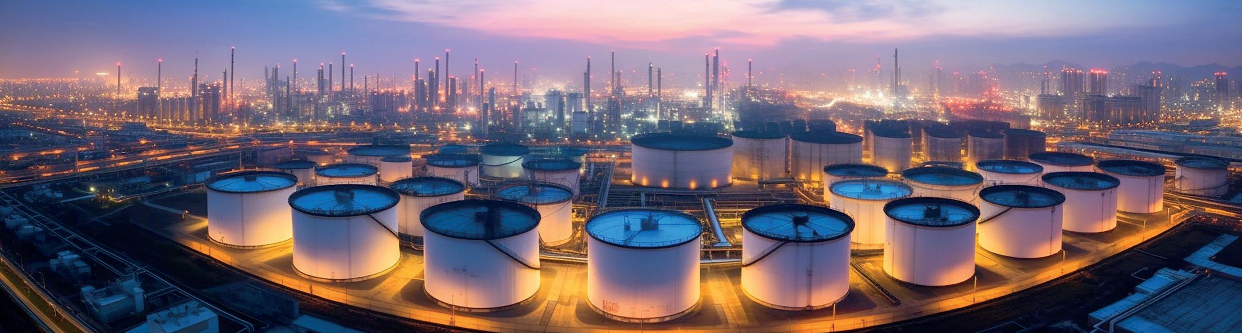

Mel Rasco is the Foam Sales and Technical Manager for Johns Manville. He has 34 combined years of experience with Dow Chemical, ITW Insulation Systems and Johns Manville, and has spent 31 of those years working with Trymer® PIR. He specialises in the production and chemical composition of the Trymer Polyisocyanurate product line. Mel holds a Bachelor of Science in Chemistry from Alcorn State University and a Master of Science in Polymer Chemistry from Virginia Tech.
01 Why are insulation systems so important in cryogenic applications?
In an LNG application, if more heat is gained than can be removed by the refrigeration system, there is potential for the system to become pressurised as the LNG vaporises. Minimising heat gain is particularly important in cryogenic applications, like LNG, and is why a well-designed insulation system is essential.
Cryogenic and below-ambient pipe and tank temperatures can drop to -297°F, making a robust insulation system critical to ensure safe and efficient operations in an LNG facility. Johns Manville is able to assist you with all the details you need to properly design, specify and install your cryogenic and LNG application.
0 2 What insulation options are available for use in the LNG sector?
When considering insulation for use on an LNG system, there are many options. Polyisocyanurate (PIR) insulation has proven to be a cost-effective choice for cryogenic insulation contractors. It is a closed cell, rigid insulation that is produced by foaming organic raw materials into a large foam block.
Other LNG insulation options include cellular glass and silica aerogel, both of which can be successfully used in LNG applications with long service lives. Cellular glass is an inorganic material that contains a myriad of closed cells. Silica aerogel is an extremely low-density solid derived from a solgel reaction in which the liquid-filled pores are replaced with gas.
PIR offers low cost per board foot, low thermal conductivity, low density (resulting in lower total system weight), ease of fabrication, and lower total installed cost. Low thermal conductivity means less thickness, which translates to a smaller outer circumference. This means fewer accessory products.
0 3 What are some of the accessory products that are required for a properly installed insulation system?
Cellular glass and PIR are both greater than 90% closed cell, while aerogel, which is open cell, has hydrophobic properties. However, properly designed and installed systems for all the insulation types require a properly installed vapour retarder, properly sealed joints, vapour stops/dams, and a good outer protective jacketing system.
Along with Trymer PIR insulation, Johns Manville also offers metal jacketing to complete the insulation system.
0 4 What factors need to be considered when designing and installing an insulation system?
When designing a robust insulation system for LNG, many factors ultimately help determine the best product. What is the desired service life? Will the insulation be in a heavily machined/busy area where it could incur more damage? Is it installed indoors or outdoors, or near an ocean/corrosive environment?
Along with considering the physical location of the project, where are the pipes themselves located and what kind of space is available for insulation (for example, are the pipes located very close together, making installation difficult or eliminating the use of certain products)? Are there fittings other than elbows within the system (such as valves, flanges and pipe supports) that need configuration? What is the budget, and does it allow for redundancy to be built into the system? What is the timing of the project and how critical is material lead time?
Johns Manville has released an updated and revised ‘LNG Systems Guide’, which covers the installation of a complete thermal insulation system on LNG piping systems, tanks, vessels and equipment surfaces (with a service temperature range of -320°F to -70°F (-196°C to -57°C) This guide is available to download on our website.
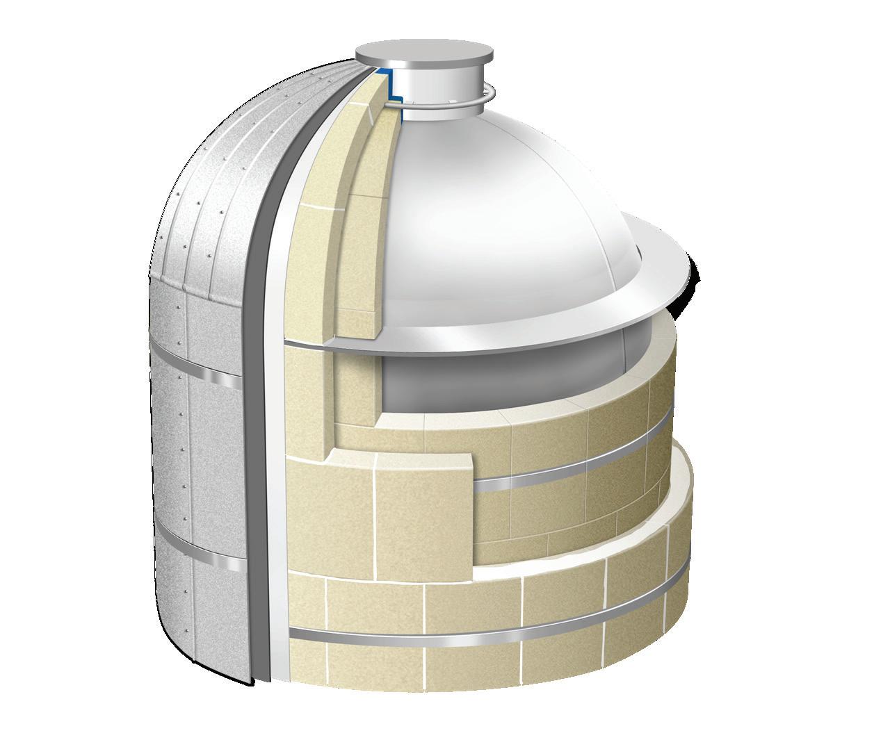


Robert English, Owens Corning, discusses the benefits of installing proper LNG impounding pit insulation and how it prevents leaks or cracks from developing.
Reliability is paramount in the utility sector where millions of customers depend on a 24/7 supply of energy to power their homes and businesses. Peak shaving, also called load shedding, is a strategy designed to support a reliable supply of power during times when demand peaks – such as heat waves or cold snaps. Utilities may also rely on peak shaving when a pipeline is shut off or unable to service customers. Peak shaving facilities rely on LNG taken from natural gas pipelines and stored in cryogenic tanks capable of holding contents at -260˚F. When additional energy is needed to meet demand, the LNG is re-gasified and available to serve customers.
Largely constructed from concrete and steel, LNG impounding basins require insulating materials that can withstand cryogenic temperatures used in LNG processes.
LNG basins are designed to collect and contain highly flammable contents that may be released in the event of a fire, pipeline leak or tank breach. This article focuses on the role that insulation plays in impounding basins at LNG facilities. It will also examine a newly constructed LNG facility in south-eastern Wisconsin, US, that relies on cellular glass insulation installed in its impounding basin to help protect surrounding wetlands and habitat. The Ixonia, Wisconsin LNG facility is the first LNG system in the US to rely on cellular glass insulation to help protect the surrounding environment.
The Ixonia LNG facility is located in a region of the US renowned for its frigid winters. The facility is designed to serve as a peak shaving facility and supplies heat to customers on the coldest days of the year. When demand for natural gas peaks, the stored LNG can be warmed to a gaseous state and made available to meet customers’ energy needs. No one wants to be without heat on a sub-freezing day, and as it makes an additional supply of energy possible, peak shaving reliably provides consistent heating for customers.
The new LNG facility in Ixonia is home to the first cellular glass insulating system installed to help protect the environment. Installed in the facility’s LNG basin, the Owens Corning FOAMGLAS® CryoSpillTM System delivers thermal shock protection designed to guard against cracks in concrete or loss of strength that can occur when ultra-cold LNG encounters concrete and steel elements in the basin.
When concrete is subjected to changes in temperature, cracking can occur, which in turn damages the structural integrity. Without an adequate leak defence system, breaches in concrete could present a path for LNG to exit the basin and potentially contaminate the surrounding area. Thus, the challenge was to insulate the basin with an impermeable material that could also deliver compressive strength.
The cellular glass insulating system delivers load-bearing performance and helps protect against cracking triggered by LNG’s cryogenic temperatures in the event of a spill. Comparable to the size of two American football fields, the impounding basin is insulated with 850 m3 of cellular glass insulation. As it protects the surrounding environment, the system also complies with standards related to basin capacity.
Recent changes to standards have set forth new capacity requirements for basins serving LNG storage tanks in the US. The standards impose requirements on the amount of a tank’s liquid contents that an LNG basin must be able to contain.1 Each impounding system serving an LNG storage tank must have a minimum volumetric liquid impoundment capacity of:
n 110% of the LNG tank’s maximum liquid capacity for an impoundment serving a single tank.
n 100% of all tanks or 110% of the largest tank’s maximum liquid capacity, whichever is greater, for the impoundment serving more than one tank.
n If the dike is designed to account for a surge in the event of catastrophic failure, then the impoundment capacity may be reduced to 100% in lieu of 110%.
The insulating system’s ability to contain liquid contents was put to the test during construction of the Ixonia facility. A total of 8 million gal. of liquid were dumped into the pit, demonstrating its capacity to contain a high volume of liquid, such as might occur in the event of a tank breach.
While impounding basins must be able to accommodate these loads, even a small leak could potentially present a contamination risk for nearby areas. A breach, break or crack in the concrete or steel infrastructure caused by thermal stress could present a path for contents to escape the basin and threaten surrounding grounds and habitat. As it provides thermal shock protection, the Owens Corning FOAMGLAS CryoSpill System supports the structural integrity of the pit’s concrete and steel components, helping to keep a spill contained in the basin.
A spill protection system should support and reinforce the steel tiebacks that help keep the pit walls straight. This added level of support is a critical factor in cryogenic applications. LNG process temperatures are around -260˚F. The composition of carbon steel also needs to be considered. Carbon steel begins to lose its strength at temperatures below -20˚F. Once installed, no mechanism is required to activate the spill protection system and it works passively to keep the steel at a temperature above -20˚F, until any spilled LNG evaporates. From an efficiency perspective, the system eliminates the need to install sacrificial concrete, and it supports streamlined design and functions with minimal maintenance across its life cycle. This renders the system easy to maintain.
Mitigating risk posed by fire at an LNG facility is an important consideration when specifying an insulating system. It is important to factor in the ability of a material to absorb liquid (wicking potential) when designing insulating systems for LNG facilities. LNG poses a significant potential to catch fire. With this in mind, evaluating the fire resistance and wicking potential of a material when insulating assets at an LNG facility is critical. The all-glass composition of the insulation means it will not wick flammable liquids. The material does not burn, does not contribute to fire spread, and will not produce toxic smoke nor generate flaming droplets which could lead to injury or contribute to fire development. These qualities make cellular glass a material well-suited for a range of industrial applications
beyond LNG, including jet fire protection and fire wall penetrations.
Every project comes with some bumps that lead to new insights – and sometimes these bumps are quite literal. This was the case when it came to achieving a smooth concrete surface in the Ixonia LNG basin. The project was constructed with pre-made concrete piles called secant piles. Secant piles are rarely insulated and the project team faced some challenges during installation. The piles had to be shot through – a practice known as shotcrete. The impact created by the high velocity application led to some areas that needed to be smoothed out to create even surfaces throughout the pit so that the insulating blocks could be installed. Owens Corning team members worked with the concrete contractors and subcontractors to get the pit walls and floor smooth in preparation for the rigid FOAMGLAS insulation to be adhered in place.
Collaboration also plays an important role in completing such immense projects. The FOAMGLAS technical team collaborated with partners and trades, including Burns & McDonnell (engineers), Payne and Dolan (general contractor) and Chicago Bridge and Iron (CB&I). At the outset, Owens Corning engineers completed calculations to help drive the specs to meet the customers’ requirements. The technical service team offers a variety of training and educational resources to support industrial projects from the start-up phase
through completion. Installation guide specifications are available to assist engineers, contractors and facility owners with all aspects of the design, installation and maintenance of insulation systems. The technical team can assist with advice relevant to process temperatures, the fire safety of applied systems and more.
As reliability remains a concern for the energy sector, LNG demand remains robust, and environmental stewardship efforts continue to advance, an insulating strategy that helps protect both the plant and the surrounding environment is important.
While the Ixonia facility relies on the Owens Corning FOAMGLAS CryoSpill System to help keep a spill from infiltrating into wetland areas, cellular glass insulation is also a strategy for passive fire safety at LNG facilities around the globe. For example, the impounding basins of LNG storage tanks in the North of France are protected with non-combustible Owens Corning FOAMGLAS insulation to reduce the vaporisation rate and minimise heat gain in the event of a pool fire. Like the Ixonia installation, the installation of cellular glass avoids possible cold spillage on the concrete and mitigates the effects on the steel-reinforced concrete that could compromise structural integrity.
1. 'Liquefied Natural Gas Facilities: Federal Safety Standards, 193.2181', up to date as of 10 October 2023, https://www.phmsa.dot.gov/ regulations/title49/section/193.2181.


Carles Ferrer, Pirobloc, explains why it is necessary to implement thermal heating solutions for oil tank storage.
Oil extraction and processing plants require a system to preserve the stored oil in its liquid state since this fluid tends to become semi-solid, or even solidify, if left for an extended period at room temperature, even when the tanks are properly insulated. The need to keep the oil in a liquid state for ease of handling makes the use of industrial heating systems crucial, with thermal oil solutions being prominent. The reliability of thermal oil heating systems is essential for preventing the solidification of fluids inside the tanks at all times.
Choosing to heat the tanks with a thermal oil system stands out as the safest and most efficient solution, surpassing the steam heating alternative. This process not only focuses on maintaining the product's temperature upon arrival at the terminal but also on slightly increasing it if the product has been transported at a low temperature.
Improper storage of hydrocarbons can lead to issues such as the inability to transfer them between tanks or internal solidification.
Immersion heaters are one of the most widely used systems in oil and gas heating processes, efficiently providing heat to various consumers used in the oil and gas industry, including specific liquids, processing equipment, and large tanks.
Immersion heaters also offer high performance in keeping liquids below freezing temperatures, which are

common during winter in cold climates. In places with low temperatures, fluids freeze faster, making it challenging to maintain their state. They are especially used in processes where rapid heating is required.
Through an indirect heating system, it is possible to achieve and maintain the required temperature with great precision and reliability, whether coil heaters, suction heaters, finned tube heaters, or other types of systems are used.
The most commonly installed heating system consists of a grid or coil through which thermal oil circulates, providing a simple solution. The arrangement of these coils at different heights ensures a uniform distribution of heat. This is common in tall tanks, as placing coils at various levels minimises natural convection and temperature variations.
It is crucial to perform engineering calculations to select the appropriate size for heating coils, ensuring the transfer of the entire power of the thermal oil boiler to the tank. The mass to be heated and the required temperature rise are essential data for this sizing. Another important parameter to consider is the pressure drop or Delta P, which affects the selection of pumps and the hydraulic circuit.
To ensure the reliability of the heating system, it is common to install two sets of thermal fluid boilers and three pumps in each installation. This way, the system
has one boiler and two spare pumps at all times, ensuring continuous heating of the process and preventing the solidification of large masses of viscous products in the tank.
The presence of two boilers allows for continuous operation even in the event of a failure of one of them. Typically, one of the thermal fluid boilers will be in standby mode, as a single boiler is capable of producing 100% of the necessary heat.
The circuit also includes three recirculation pumps, with two spare pumps to ensure operability in various operating configurations. Any of the three pumps can operate with any boiler using a manual valve system.
On the other hand, the system can also be designed so that both boilers operate simultaneously. In this case, the boilers can deliver the entire installed power if the process demands it.
Some installations also incorporate a suction heater in the tank, in addition to the heating coil. The suction heater’s function is to reduce the viscosity of the product in the suction area through an open-mouthed exchanger, where thermal oil tubes are in direct contact with the transported fluid. The suction heater keeps the product in a liquid state and facilitates proper transfer when needed.
The suction heater is attached by a main flange to the tank wall, typically located at the bottom and near the product suction area. An external flange on the tank allows the exit of the heated product at the appropriate temperature for transfer.
The heating surface and power are selected accordingly to meet the process requirements. Variables to consider for its configuration include the product characteristics inside the tank, viscosity, tank volume, and flow rate.
There are two fundamental categories of heating methods: direct and indirect. Direct heating involves the stored product in the tank coming into direct contact with the heat source, while indirect heating uses an intermediate fluid to transfer energy from the heat source (the heater) to the tank, where it is transferred to the stored product.
In direct heating, electric resistors inserted into the storage tank are employed. Typically, three or four sets of resistors are used, located at different points at the bottom of the tank. This system offers efficiency since there is no energy loss between the energy source (the resistors) and the product being heated. Any issues with one of the resistors can be quickly resolved by replacing it with a new one. This replacement operation is particularly fast if the tank is empty.
However, this method requires high electricity consumption and the installation of resistors rated for specific areas, making it economically unviable in most cases unless dealing with tanks of reduced capacity or located in areas where installing an indirect heating system is challenging.
Another issue associated with direct heating using electric resistors is the direct contact between the resistor’s surface and the product to be heated. Hydrocarbons typically have relatively low flash temperatures. This necessitates keeping the film temperature equally low. In practice, the film temperature is the temperature of the fluid droplet in contact with the heating surface. Given the direct contact between the heating resistor and the fluid, this film temperature can be excessive, leading to the overheating of the hydrocarbon with the subsequent risk of ignition and endangering the safety of the entire plant.
An indirect heating system involves the installation of an energy transport circuit where a heat-carrying fluid flows from the heat source (the boiler) to the heat consumer (the tanks).
The energy transfer occurs through coils or heat exchangers, and then the fluid returns to the thermal fluid boiler. During this process, no heat is added or removed between the system’s walls, except for losses to the environment, which are minimised through efficient insulation of the pipe network.
The fluid used to transmit heat from the boiler to the tank must meet certain characteristics to be efficient and economical, including:
n Good heat transfer properties.
n Thermal stability.
Notes:
* Tanks 2, 3, 7 and 8 are grouped for calculations of loss to the environment.
** Tanks 5 and 6 are grouped for calculations of loss to the environment.
*** Tanks 1 and 11 are grouped for calculations of loss to the environment.
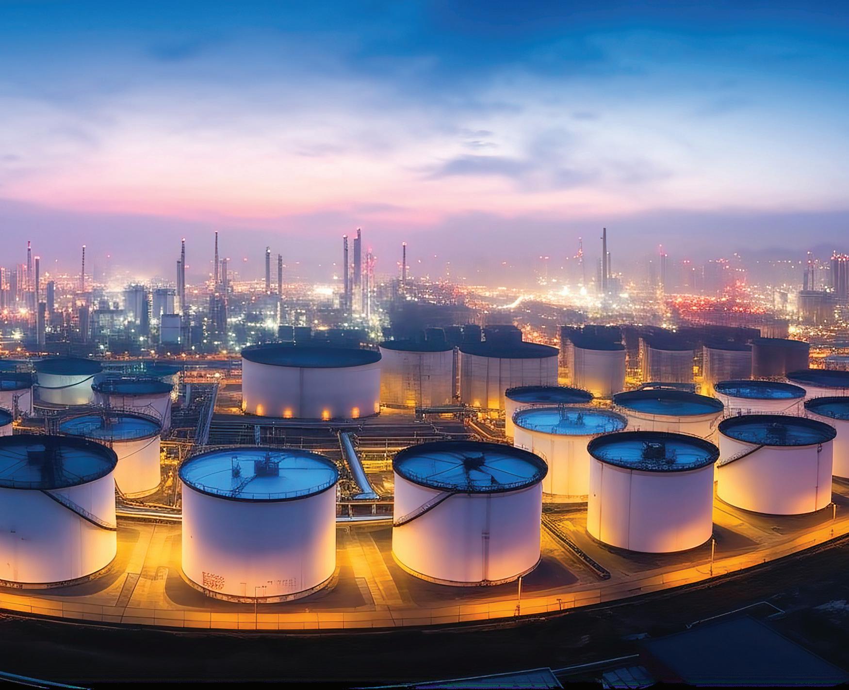
n Low viscosity.
n Low solidification temperature.
n Low corrosion.
n Technical suitability for the process.
n Low toxicity.
n Ease of disposal at the end of its life.
Thermal fluids and steam are the most commonly used heat transfer mediums. Although each has its pros and cons, thermal fluids stand out for various reasons including:
n Efficiency.
n Ability to work at high temperatures and low pressures.
n Precision in adjusting the final product temperature.
n Versatility.
Any thermal fluid installation with a total capacity greater than 1000 l must have a collector tank, located at the lowest point, capable of receiving the total quantity of liquid from the installation. This collector will have a ventilation and drainage device. It is recommended that the collector tank capacity is 23 m3
Heat transmission installations must incorporate an expansion tank of sufficient capacity. Depending on the volume of the installation (greater or less than 1000 l), an expansion tank must be available that can absorb from roughly 1.3 – 1.5 times a possible volume increase in the liquid load of the installation at the maximum temperature of the heat-carrying liquid. The connection of the tank to the atmosphere will be made freely and safely through the collector tank, so that there is no excess pressure. It is recommended that the expansion tank capacity be 7 m³.
Case study: Ducar Oil Co., Spain
Ducar Oil Co. requested a thermodynamic study from Pirobloc for the fuel oil storage tanks at its terminal in Ceuta, Spain. The company currently has a steam system that it wants to replace with a thermal fluid system.
The fluid to be heated is HFO-380 fuel oil with the following characteristics at 50˚C:
n Viscosity: 380 cSt.
n Density: 938 kg/m³.
n Specific heat: 0.45 kcal/kg·K.
n Thermal conductivity: 0.119 W/m·K.
Ambient conditions for calculating energy loss to the environment:
n Outside temperature: 10˚C.
n Wind speed: 10 m/s.
Other data and calculation assumptions:
n Fuel oil storage temperature: 50˚C.
n Product level in the tank: 80% of total height.
n Side insulation thickness: 80 mm expanded polyurethane foam.
n Insulation thermal conductivity: 0.03 W/m·K.
n Soil thermal conductivity: 2 W/m·K.
n Tank cover: no insulation.
Thermal calculations for environmental heat losses should consider the following tank situations:
n Heat losses through the soil.
n Heat losses on the side submerged in the product.
n Heat losses on the side not submerged in the product.
n Air chamber between product and roof.
n Heat losses through the uninsulated roof.
Table 1 presents thermal calculations for the tanks, considering both the main calculation (to compensate for heat losses and maintain temperature) and the secondary calculation (to increase the temperature of each tank by 5˚C in 24 hours).
The preliminary sizing of two thermal fluid boilers, each with a capacity of 1800 kW, is considered appropriate, providing a total heating capacity of 3600 kW.
Although the total boiler power is less than the calculated maximum power (4423 kW), a 100% simultaneity in
tank heating is not anticipated under reasonably foreseeable conditions.
In most situations, the plant is expected to operate with a single boiler, keeping the second boiler on standby in case of an incident with the main boiler or as support for the primary boiler during exceptional thermal demand peaks.
When operating the boilers non-simultaneously, it is recommended to alternate the boiler acting as the primary and secondary to distribute wear and maintain both units in optimal service conditions.
Based on the total thermal power of each boiler, the following flows are calculated with a maximum thermal jump of 30˚C between the thermal fluid supply and return:
n Boiler power: 1800 kW.
n Boiler flow: 110 m³/h.
n Nominal diameter of boiler elements: DN125.
n Boiler power: 3600 kW.
n Boiler flow: 220 m³/h.
n Nominal diameter of the main line: DN200.
The sizing of the tank supply and return intakes is performed based on the same calculations as stated earlier.
According to Ducar Oil Co.’s previous plant records, it is supposed to provide heat to the tanks using radiators consisting of a row of longitudinally finned tubes.
Each radiator consists of:
n A thermal fluid supply manifold.
n The input manifold that feeds five tubes.
n Thermal fluid return manifold.
Thermal calculations are carried out for each radiator, resulting in 60 kW per unit. The number of radiators needed for heating each fuel oil storage tank is proposed, taking into account two criteria:
n Number of boilers analogous to the Ducar-2 fuel oil storage plant.
n Number of boilers according to the calculated thermal power.
Since each radiator has five tubes, the circulating flow for each radiator under optimal conditions ranges between the following values:
n Minimum flow: 4.5 m³/h.
n Maximum flow: 10 m³/h.
The pressure drop (or pressure loss) of the radiator based on the indicated flows and with an average temperature of 165˚C is:
n Pressure drop at 4.5 m³/h flow: 0.05 bar.
n Pressure drop at 10 m³/h flow: 0.23 bar.
The final number of heaters is the result of the thermal study conducted as shown in Table 2.
According to the bottom coil data, the nominal flow is calculated:
n Tank N2 has two inputs and two outputs for the coil, so the total flow will be distributed between both coils.
n The pressure drop for a flow of 20.5 m³/h is estimated at 0.05 bar.
n Tank N11 has a single input and output for the coil. The pressure drop for a flow of 5.4 m³/h is estimated at a 0.01 bar. The reason for the low pressure drop is the pipe size, which is 3 in., so it is highly oversized for a flow of 5.4 m³/h.
It is determined to size the pipe diameter based on the maximum thermal fluid flow that the radiators are capable of absorbing.
This will allow the tank to receive a higher flow than calculated for its nominal power in case of a peak heat demand, allowing it to operate with a reduced temperature difference and increase heat transfer.
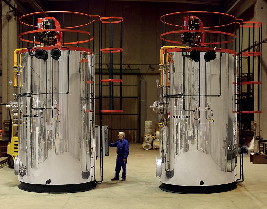
According to the results and the proposed PID, data is entered into calculation software for hydraulic simulation.
After analysing the results of these simulations, it is proposed to implement a small bypass at the end of the DN25 line, to which an orifice plate will be added to maintain a certain flow volume until the end of the main line, which will keep the temperature close to the boiler outlet. The function of the orifice plate is to limit the flow through the end-of-line bypass.
For the simulation calculations, a set point of a differential pressure of 1.5 bar is established for the general bypass valve located in the boiler room:
n In case the differential pressure exceeds 1.5 bar, the valve must open to allow fluid passage and lower the differential pressure.
n If the differential pressure is below 1.5 bar, the valve must close so that the boiler flow is available to the heat consumers.
n In many scenarios, the bypass valve will be completely closed due to the low differential pressure of the heating tanks.
Non-standardised components such as the thermal fluid boiler, radiators, and others are registered as new Kv components, to which their hydraulic characteristics have been introduced at a known point of flow, pressure drop, and fluid density, allowing the software to calculate pressure drop under any other circumstances.
The distribution of flows is proportional to the tank size (larger tanks receive more flow than smaller ones). It is observed that in the extreme case of only supplying the two closest tanks and the two farthest tanks from the boiler room, the farthest tanks are not adversely affected by the opening of the nearby tanks. The thermal fluid pump flow is always equal to or greater than the nominal flow of the boiler. Based on the above, the proposed pipeline sizing by Pirobloc is considered valid.
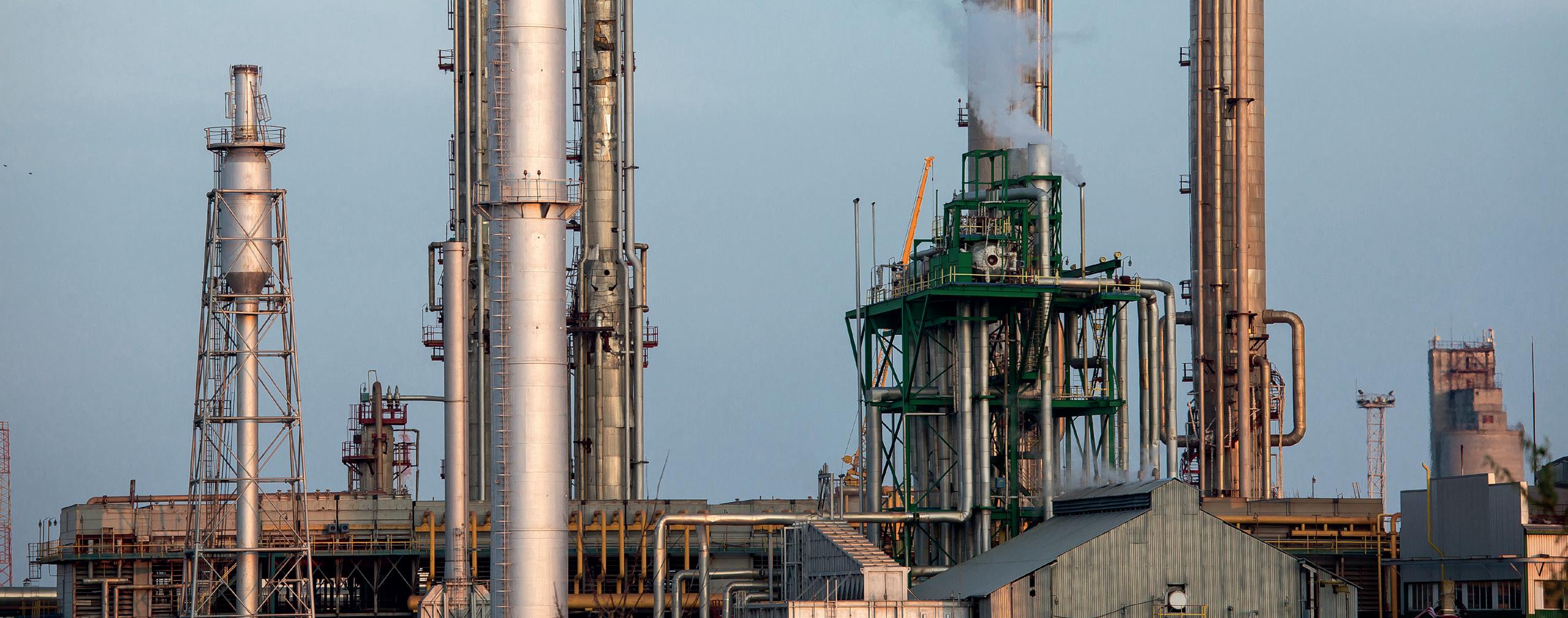
•
•
Tank farms, with their vast arrays of storage tanks, serve as critical nodes in the supply chain of various industries, including petrochemicals, oil and gas, and chemical manufacturing. The sheer scale and volatility of the substances stored in these tanks, as well as the potential for catastrophic incidents, makes tank safety paramount. This article examines safety systems on floating roof tanks, particularly rim seal fire protection systems (RSFPS). Selecting the right instrumentation for such a system is crucial for tank storage safety.
There are several standards that are associated with RSFPS. The ‘API RP 2001: Fire Protection in Refineries’, which was

published by the American Petroleum Institute (API), provides guidelines for the design and installation of fire protection systems in refineries, including recommendations for rim seal fire protection. The National Fire Protection Association (NFPA) published a standard, ‘NFPA 11: Standard for Low-, Medium-, and High-Expansion Foam’. This standard covers the design, installation, operation, and maintenance of low-, medium-, and high-expansion foam systems, which may be used for rim seal fire protection. In Europe, there is the ‘EN 13565-2: Fixed firefighting systems - Foam systems - Part 2: Design, construction, testing’. This standard provides specifications for foam systems, including those used for rim seal fire protection. In specific countries like India, there is the ‘OISD-STD-117: Fire Protection Facilities for Petroleum Depots,
Terminals, Pipeline Installations and Lube oil installations’, an Oil Industry Safety Directorate (OISD) standard which is being used to design rim seal protection systems.
A RSFPS safeguards floating roof tanks (Figure 1), the most common type used in tank farms. These tanks consist of a roof that floats on the stored liquid, allowing for minimal vapour emissions. The rim seal is the area where the roof meets the tank shell, forming a critical seal. However, this area
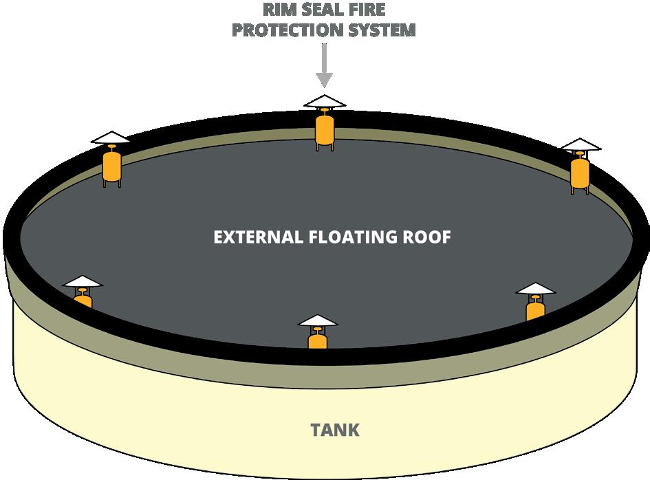
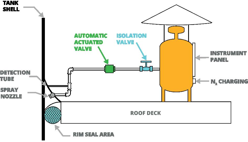
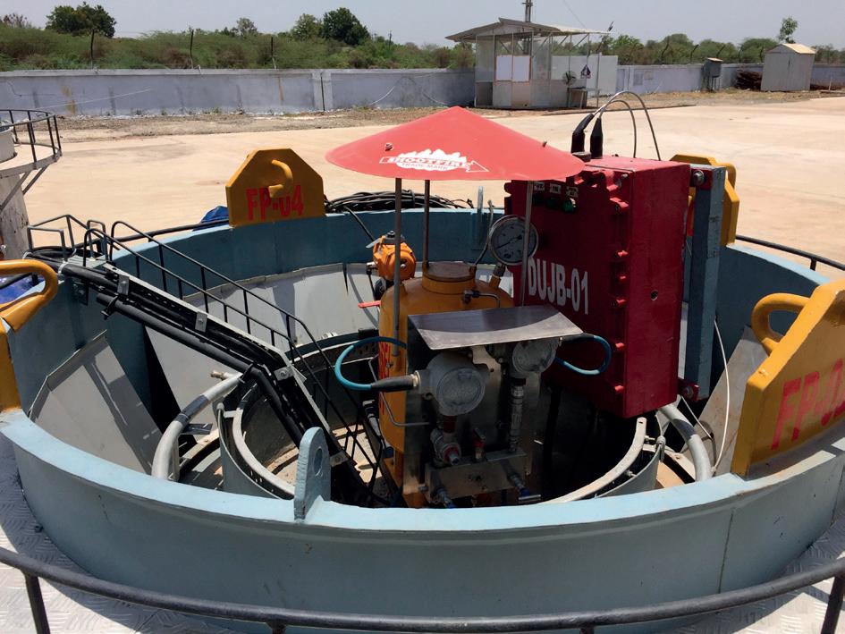
is vulnerable to fires due to lightning strikes, static electricity, or equipment malfunctions. 90% of fires in open floating roof tanks start in the seal between the floating roof and the tank wall, known as the rim seal.
A RSFPS (Figure 2) detects and suppresses fires at the earliest stages and typically comprises three key components:
n Detection system: this includes sensors like heat detectors, flame detectors, or fusible elements strategically placed around the rim seal. These sensors quickly alert the system of even minor fire outbreaks.
n Extinguishing system: this consists of a network of pipes, nozzles, and pressure tanks containing the necessary pressurised fire-suppressing agents like foam or water. Upon detection, the system automatically releases the agent, extinguishing the fire efficiently.
n Control system: this central unit monitors the sensors, receives alarm signals, and activates the extinguishing system.
Instrumentation plays a pivotal role in the effectiveness of a RSFPS. The roof of the tank is an unmanned area where access is restricted, which makes instrumentation all the more important as it serves as the eyes and ears of the system. Various sensors, including those for pressure, level, temperature, flow, and heat, are strategically placed to monitor conditions and identify abnormalities. Precise and reliable instrumentation ensures that:
n Real-time data is communicated continuously: instruments like sensors and transmitters provide data on factors like temperature, pressure, and flow rate. This data allows the control system to predictively monitor the system’s health, enabling proactive maintenance and minimising downtime.
n Accurate detection: sensors positioned strategically around the rim seal detect fire at the earliest stages, minimising the potential for damage.
n Extinguishing agent delivery is optimised: by analysing data from various sensors, the control system can optimise the delivery of extinguishing agents, ensuring effective fire suppression while minimising waste.
The RSFPS has a control system unit that monitors the sensors, receives alarm signals, and activates the extinguishing system (Figure 3). The following is a set of criteria that designers of RSFPS would look for in their instrumentation:
n Reliability: the instrumentation should function dependably even in harsh environments and extreme conditions. This is likely the most important factor as it ensures the RSFPS can perform its mitigation function, which can determine if there is minimal or severe damage to plant assets and personnel. A trustworthy instrumentation brand with superior performance is recommended.
n Durability: the instrumentation should be built to withstand weather elements and the long-term wear and tear of a tank farm environment. An IP66 or NEMA4X rating should be a minimum.
Figure 1. External floating roof. Figure 2. A rim seal fire protection system (RSFPS).

ILTA 2024, the leading conference and trade show for the bulk liquid terminal industry, is set to be our biggest yet!
Join thousands of terminal industry professionals from around the world for:
Inspiring keynotes plus in-depth educational sessions featuring expert speakers
The ILTA exhibit floor packed with hundreds of industry solution providers
World class networking including a special celebration of ILTA’s 50th anniversary
All in Houston, TX—the Energy Capital of the World!
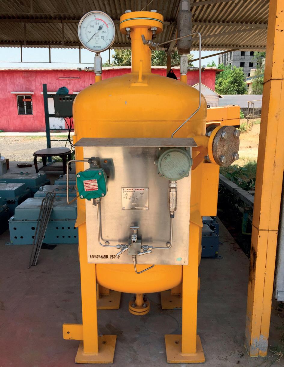
n Accuracy and stability: precise measurements and data are essential for effective pressure monitoring, fire detection and suppression. In the instance of pressure readings, setpoints would be stable over temperature and time.
n Easy maintenance and after-sales service: simple maintenance procedures (e.g., field calibration with minimal tools) and readily available spare parts with quick lead times are crucial to minimise downtime and maintain system performance.
n Remote diagnostics: since the roof of the tank is an unmanned area, a device with remote diagnostics capability can inform the user if the instrument needs to be replaced immediately instead of waiting for the next maintenance round to discover the faulty instrument.
n Compliance with standards: instruments must comply with relevant international industry standards and regulations for safety and performance.
The consequences of selecting inferior instrumentation for the RSFPS can be severe and far-reaching. False alarms triggered by unreliable instrumentation can lead to unnecessary shutdowns and interruptions in operations. This not only incurs financial losses but also disrupts the efficiency and continuity of industrial processes. The ramifications of these disruptions can extend beyond immediate financial implications, affecting the reputation of the facility and its operators.
In addition, inaccurate or unstable readings or delayed response times due to faulty sensors can result in the system
failing to detect a fire in its early stages. This, in turn, may lead to the uncontrolled escalation of the fire, causing significant damage to assets, posing environmental risks, and jeopardising the safety of personnel. Non-compliant instrumentation can lead to significant fines and legal repercussions for regulatory violations.
The following case study demonstrates how a global RSFPS manufacturer, Vimal Fire Controls, partnered with a global instrumentation manufacturer, United Electric Controls, to design a reliable RSFPS for some of the largest clients in India.
Vimal Fire Controls manufactures RSFPS for floating roofs in tank storage facilities for facilities in India and the Middle East. A few common challenges arise in the design of a RSFPS:
n There is limited real estate on a tank roof. Space is a premium and hence the RSFPS must be compact in design.
n The extinguishing agent is only as effective as its coverage on the tank roof. This is heavily dependent on the agent’s discharge pressure. The effective functioning of the RSFPS is hinged on the reliability of the pressure monitoring device on the RSFPS.
n Maintenance efforts required on top of these storage tanks can be a hazardous and labour consuming process.
Vimal Fire Controls selected United Electric Controls’ (UE) All-Stainless-Steel, SIL2-rated, compact 12 series pressure switch as the pressure instrumentation on the RSFPS. The discharge tanks (Figure 4) are pressurised to 15 kg/cm². When the pressure falls to 12 kg/cm², an alarm is triggered by the pressure switch to notify the operator that there is insufficient pressure in the tank. Insufficient pressure reduces the trajectory of the extinguishing foam, leaving areas of the tank susceptible to fire.
The 12 series was ideal for this application as it was compact enough to be fitted on the foam agent tank. The pressure switch has a Belleville spring design that provides the instrument with setpoint stability to eliminate false trips and reduce costly maintenance.
UE was chosen by Vimal Fire because of its reputation worldwide as a manufacturer of reliable instrumentation used in safety, alarm and shutdown applications. The 12 series also has two major certifications, UL and ATEX, which were requirements for the majority of its customers.
RSFPS are a critical component of safety measures in tank storage facilities, particularly for floating roof tanks. The selection of high-quality instrumentation is central to the effectiveness of such a system. Investing in reliable, sensitive, and interoperable instrumentation not only enhances the safety of tank storage facilities but also ensures the continuous and efficient operation of industrial processes. Conversely, the consequences of neglecting the importance of proper instrumentation selection can be severe, jeopardising not only the assets within the tank farm but also the overall integrity and reputation of the facility. It is vital for engineers to understand the crucial role that instrumentation plays in a safety system.
Dr Alexander Zelck, TIMM Technology Germany, explores how proper grounding and overfill prevention increases terminal safety and performance.
The loading of flammable liquids is a daily operation at storage terminals. Large quantities are handled via tank trucks, tank containers, railway tank wagons or tanker ships. Additionally, barrels or intermediate bulk containers (IBCs) are occasionally filled. The more efficient and safer these loading processes are, the more efficient and safer the operation of the entire storage facility is.
The main factor influencing loading terminal performance is the application of a modern loading technology. ‘Modern’ refers to advantages in terms of occupational safety, environmental protection, product flow rate, and automation possibilities. For example, in the distribution of fuels by road tankers, bottom loading can be considered a more modern loading technology compared to top loading.
After selecting a loading technology, the level of loading automation needs to be decided. This involves precise metering, blending, additivities and marking, access control, identification and truck queuing, electronic clearing, and the control and IT backbone (PLC, SCADA, TAS, TMS, ERP connection). Automation enhances the performance of the utilised loading technology and allows for the optimisation of the preceding and subsequent loading processes.
Loading always involves the flow of a liquid, and the flow of low conductive liquids, such as hydrocarbons, is a process that generates electrostatic charges. Regardless of the loading technology or

automation level, operators must always consider electrostatic charges. The generated charge can accumulate on the liquid, on the container/tank, and generally on all elements involved in the liquid flow line. The more that charge accumulates, the greater the risk of a discharge spark.
The particular danger lies in the fact that most fuels and liquid chemicals are flammable. Depending on their flash point, flammable vapours may also evaporate from the liquid. These vapours mix with air and can create an explosive atmosphere. It should be noted that vapours can also creep into adjacent areas through channels and pits. Within this potentially explosive area, electrostatic discharges (such as sparks) can lead to the ignition of the flammable air-vapour mixture, resulting in an explosion.
To counteract electrostatic charges, grounding must be applied. Grounding means connecting a conductive or dissipative object in such a way that electrostatic charges can safely dissipate into the earth. The physical requirements for this grounding connection are not particularly high. Since electrostatic charges involve high voltages (kV) with simultaneously low currents (mA), an electrical resistance of 10^6 ohm is more than sufficient in most cases.
Sometimes a value of 10 ohm is mentioned as a requirement for the discharge resistance. However, this can be misleading. This value is solely to facilitate the measuring of a grounding connection; using a hand-held multimeter for instance. In real terms of discharging
electrostatic charges, there is no significant difference between having a resistance of 10 ohm or 10^6 ohm. The crucial factor in daily operation is not the value of the resistance, but that a grounding connection is made at the right time and to the right object.
Electrostatic grounding can be realised through the establishment of installations for equipotential bonding or lightning protection. These are the green-yellow cables that connect all elements of the loading system together and to a foundation ground. In this way, dangerous charges from the loading skid, pipes, fittings, etc. can be avoided – assuming that these connections are in place and correctly installed on every element.
When considering mobile tanks or containers for the intake or outtake of liquids, it is clear that these cannot be permanently integrated into the grounding and equipotential bonding system with firm cables. But without a doubt, these objects also need to be reliably grounded.
The basic principle of grounding movable tanks and containers is very simple: a conductive grounding cable with a grounding clamp is installed at the filling station. It has a firm connection to the equipotential bonding system/the structure. Before the closure of the mobile tank/object for
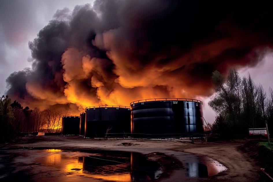
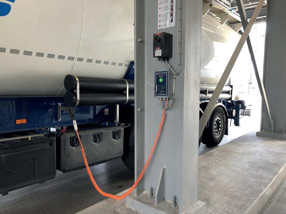
filling or emptying, the grounding clamp must be attached to the designated grounding point at the tank/object. It remains there until the filling and resealing of the tank is finished.
A significant potential hazard lies in the fact that the establishment of ‘temporary grounding connections’ depends heavily on manual processes. Further potential hazards that can be found at loading stations include the following:
n Presence and release of flammable vapours.
n Leaked, dripped or spilled liquids.
n Isolated tanks and containers (trucks with rubber tyres, IBCs standing on concrete floors).
n Rusty grounding tabs, painted drums.
n Grounding clamps which are not secured and can be accidentally pulled down.
From the physical perspective, electrostatic grounding is fulfilled when the grounding clamp is attached to the object to be grounded. However, from an operational safety standpoint, this is far too little.
To truly ensure that a conductive grounding connection has been established, it must be electrically measured. A purely visual supervision of electrical connections is not possible.
The aim of measuring the established grounding connection is to detect possible cable breaks or any non-conductive attachments of the clamp. Improper connections can come from clamping on rusty/dirty/painted surfaces or handling mistakes by the operator. However, manual measuring of the contact and discharge resistance is not practical during loading operations. Another important criterion is that the liquid transfer must not be started and must immediately stop when grounding is not present.
The aforementioned points can only be mitigated through automatically working grounding control devices. Their use is often mandatory in large companies and is even legally required in some countries. Yet, there are still many filling stations where either no safety measures are in place, or outdated grounding equipment is present.
Electronic grounding control devices are equipped with a grounding cable and a grounding clamp. Once the object is contacted, they continuously measure whether a sufficient grounding connection is present. If it is, they indicate it to the operator with a green light. If there is no good grounding connection, they typically display red. In addition to the visual indication, grounding control devices have control outputs to connect to the filling station control system. This interlock function is very useful. Only when it detects good grounding will the liquid transfer be possible. If the grounding is lost, the liquid transfer, and thus the generation of electrostatic charges, are immediately interrupted.
Not all grounding control devices are the same. Modern grounding control devices have an object detection function. They only switch to permissive when the grounding clamp is connected to a ‘plausible’ object. Such an object detection function is available for tanker trucks and tank trailers as well as for dissipative plastic drums and FIBC type C.
Figure 1. Electrostatic sparks can ignite flammable liquids.If the grounding clamp is connected to a different object (for example, directly to the frame of the structure), the loading permissive is reliably denied. In this way, the operator is encouraged to use the grounding equipment properly. The operator can only load when a ‘plausible’ object has been connected. When monitored grounding is installed and connected to the loading control system, its use is inevitable and not subject to personal decision. Otherwise, the actual use of grounding clamps is hardly enforced.
In fuel distribution, two different types of loading technologies are to be distinguished. Road tankers can be loaded through the dome lid (top loading) or via bottom valves (bottom loading). Top loading is the historically older loading technology and still widely used in emerging and developing countries. In Europe, top loading for fuels has been replaced by bottom loading at most terminals. Advantages of bottom loading for storage terminals include:
n Reduction of loading times by up to a quarter compared to conventional top loading. Vehicle tank compartments can be filled simultaneously with a flowrate up to 2500 l/min each.
n Reduction of the processing time at the terminal to potentially 15 mins from entrance to exit, including product loading and all paperwork, with a capable Terminal Automation System.
n Enhancement of occupational safety as operators are no longer exposed to toxic vapours when filling through the dome hatch. All operations can be carried out at ground level with no risk of falling.
n Reduction of product losses and preventing emissions by use of a closed collection and recovery system for displaced vapours.
n Loading gantries can be constructed with lower roof height. Platforms, stairs, ladders and fall prevention systems are not required.
n Multi-product loading bays allow for the loading of different products at the terminal simultaneously into tankers. Each loading bay can accommodate different products like unleaded, super unleaded, diesel, and kerosene.
n Standardised technology by API Recommended Practice 1004, European Directive 94/63/EC, European Standard EN 13922.
Overfill prevention is mandatory when bottom loading because of the high filling speed and simultaneous loading into different tank compartments. The necessary safety precautions cannot be guaranteed by a supervising operator with manual intervention. To meet these requirements, combined control units for overfill prevention and electrostatic grounding are used. These control units are installed at the loading gantry. They connect through a standard plug-socket connection to the tanker truck and further to the sensors at the top of the tank compartments. In case the truck’s tank or a compartment is overfilled, the overfill prevention controllers trigger to immediately
shut down the loading. The same applies if the electrostatic grounding is not sufficient.
Overfill prevention controllers can switch automatically into the correct operating mode according to the detected type of truck installation (sensor types). On their display they give instructions to the operator and indicate critical situations accurately. This includes the verification of electrostatic grounding and single identification of the overfilled tank compartment. A separate grounding control device is not necessary when using an overfill prevention controller.
Intelligent control devices for grounding and overfill prevention embody efficiency and safety advantages through appropriate automation. Essential characteristics include the following:
n Designed according to an intelligent explosion protection concept (IEPC), which allows the control devices to be opened while being energised, inside the hazardous area. This facilitates installation, configuration, and troubleshooting. It also enables the rapid replacement of worn-out grounding cables and clamps without having to shut down the adjacent loading operation.
n Control outputs for integration into the loading control system. Rendering loading only possible when the permissive signal is present. For the highest degree of safety, device-monitored potential-free contacts or NAMUR compatible signal outputs (IEC 60947-5-6) should be present. With NAMUR outputs, the signal path to the PLC can be monitored for short circuit or cable break.
n Self-monitoring function of the device and switching to a safe state (no loading authorisation) in case of a fault. This includes monitoring for external EMC influences. Ideally complemented by the compensation of factors that could disturb the reliability of measurement, such as parasitic capacitances from cable length, moisture, snow, and road salt.
n Object detection function, ensuring the grounding device only activates on plausible objects. This is adjustable and configurable on site. The function is ideally suited for grounding control devices for road tankers, silo vehicles, FIBC type C, and barrels made of conductive plastics. Furthermore, it protects against operator misuse.
n When bottom loading fuels, it is important to use an overfill prevention controller with integrated electrostatic grounding, multi compartment monitoring, status indication of individual compartments, and text display for operator instruction.
Loading technology and appropriate automation is essential to future-proof storage terminals. Bottom loading is the most modern loading technology for fuels and can be protected reliably by an overfill prevention controller. For general filling applications, grounding control devices with an object detection function reduce the risks associated with improperly executed grounding connections. Overfill prevention and monitored grounding directly increase terminal safety and allow for a significant reduction in labour-intensive supervising and electrical measurement of grounding cables – freeing up operator personnel for important tasks.
Real-time monitoring and timely detection of oil and fuel spills are crucial for environmental protection, asset safeguarding, and the health and safety of humans and wildlife. An effective early warning system and rapid response to leaks and spills minimises cleanup efforts, reduces the risk of fines and penalties, demonstrates an organisation’s commitment to environmental stewardship, and enhances risk mitigation and resilience to spill events, ultimately lowering overall risks and associated costs.
Recent advancements in fluorometric sensor technology have led to the development of sensors that provide more accurate non-contact detection of even the smallest liquid hydrocarbon leaks. These new sensors offer expanded capabilities to reliably monitor a wider range of petroleum products on both water and dry surfaces. They can also be deployed and installed in more challenging environments and applications that are not possible with traditional sensors.
This article will explore the benefits offered by new fluorosensors, which utilise the well-established fluorometric sensing principle with unique optical and electronic designs.
Fluorometric sensors emit ultraviolet (UV) excitation light pulses (Figure 1) onto the monitored surface at a user-defined
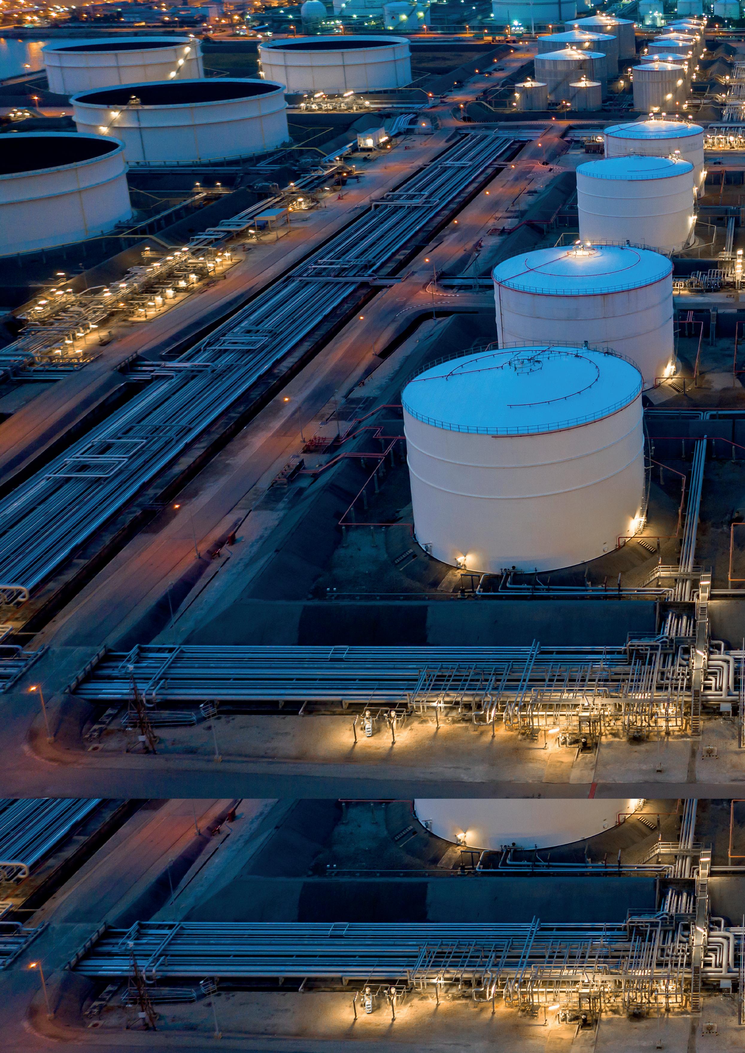
frequency. When the light interacts with hydrocarbon contamination, it induces the emission of light at longer wavelengths, known as fluorescent light. The sensor then detects this fluorescence and measures its intensity. Upon reaching a user-defined threshold, the sensor triggers an alarm notification that is transmitted to the destination, such as a monitoring centre, for response via wired or wireless means.
New sensors, such as those developed by LDI Innovation Ltd (represented in the US and Mexico by PhotonTecTM), can provide continuous and reliable operation 24/7 in bright daylight and in total darkness. For traditional sensors, sunny ambient light conditions, or algae, for example, may cause false alarms. These are eliminated by the intelligent filtering mechanism offered by modern sensors.
Traditional fluorosensors are limited to using UVA excitation wavelengths between 315 and 400 nm, which effectively detects crude oils and medium-weight and heavyweight petroleum products such as diesel oils, fuel oils, and lubricants.
However, UVA-only sensors struggle with or even fail to detect very light and light oils such as gasoline and jet fuels. The UVB band (280 – 315 nm) is significantly better suited for these
products. LDI Innovation Ltd’s BlueHawkTM and TinyHawkTM sensors can be configured for UVB, which makes them capable of accurately detecting lighter oils. This opens up a range of new applications for fluorometric sensing at fuel storage facilities, oil refineries, pipeline systems, and fuel terminals.
The patented LED-based optical design of the BlueHawk sensor utilises the same single set of large lenses for transmitting the excitation light pulses and receiving the fluorescence emission, whereas other sensors use two separate sets of much smaller lenses. Large apertures provide efficient light delivery, improving the sensor’s signal-to-noise ratio and boosting sensitivity to detect spills. This virtually eliminates false alarms, as the sensor does not need to operate at the edge of the detection window, which is a common issue with conventional fluorometric sensors.
The sensor’s optical design also incorporates internal health-check and control functions for the sensor’s UV LED using a reference detector. The detector continuously monitors the intensity of the UV pulses and automatically adjusts it as the sensor’s operating temperature changes or the LED ages. In addition to the robust LED UV light source, this further extends the sensor’s service life and its mean time between failures (MTBF).
New sensors also offer longer detection ranges of up to 33+ ft (10+ m), which broadens the available applications for fluorometric spill detection. They also provide a high tolerance for varying sensor-to-surface distances, caused by high waves or large tidal ranges, for instance.
Traditional fluorosensors typically offer scan rates up to 2 Hz (two UV pulses per second). This is adequate for monitoring static surfaces such as concrete, soil, or stationary water, but it is often insufficient for accurate oil detection in turbulent or rushing waters. Modern sensors can operate at a maximum rate of 10 Hz, significantly improving detection reliability in such environments.
New sensors also offer a broad angle of incidence (± 45˚). Traditional sensors operate vertically only, and they stop detecting fluorescence when the scan angle exceeds a few degrees. Modern sensors can be installed onboard vessels, at cramped sumps, and in other environments where vertical installation is difficult or impossible. The broad angle of incidence also delivers improved detection accuracy in rough waters where the


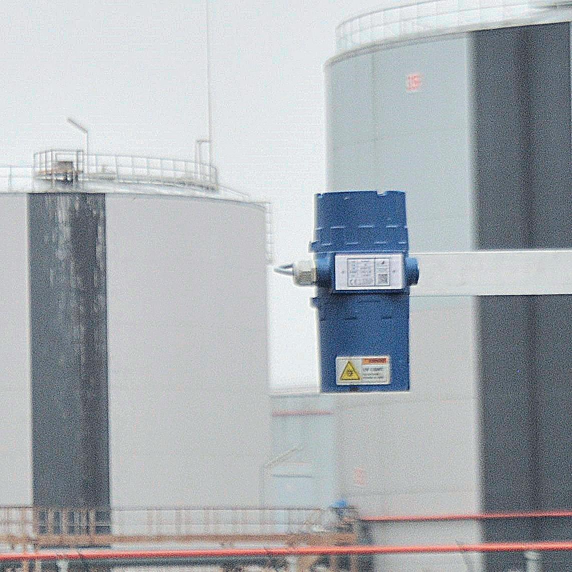
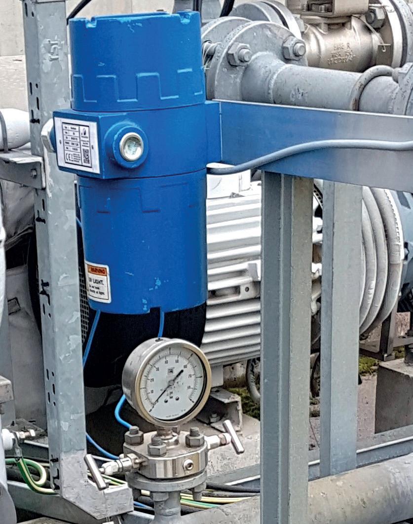
surface topography and angles continuously change.
This combination of long detection range and broad angle of incidence enables modern sensors to be mounted on motorised pan-tilt fixtures, allowing a large surface coverage of up to 1600 ft2 (150 m2). In contrast, vertical-only long-range sensors cover up to only approximately 33 ft2 (3 m2). This means a single new sensor can monitor approximately 50 times larger areas than traditional long-range sensors, lowering the number of units needed in multi-sensor systems.
New sensors come in a NEMA 6P (IP68) rated standard enclosure, providing the most durable and watertight protection available for an electronic device. As such, they can cope with occasional prolonged submersion in water. Traditional sensors, meanwhile, are less watertight and typically use NEMA 4X (IP66) enclosures, allowing hose-downs but no submersion.
Optional ATEX-certified enclosures enable sensor deployment in hazardous and explosive environments across industries like oil and gas, petrochemical, chemical, and mining.
Leveraging the latest optical and electronic innovations, modern sensors are smaller, lightweight, and offer low power consumption. This enables novel deployments on solar-powered buoys, aerial drones, and other battery-powered equipment.
Modern sensors are powered by safe 10 – 30 DC voltage, and an AC/DC converter can be used where only AC supply is available. The sensors offer remote access to enable them to be set-up up directly from the monitoring centre. For wired alarms, a sensor can use its serial RS485 data connection, analog 4 – 20mA current loop, or SPDT relay contacts. Wireless alerts by email or SMS messaging may also be available with optional equipment.
Modern sensors can also operate in standalone or networked modes, allowing up to 128 units to work in a single easy-to-expand system.
It is also possible to equip new sensors with optional surface distance measurement to further improve detection accuracy in applications with extreme sensor-to-surface distance variations, such as areas with macro-tidal ranges. Another optional piece of equipment available to the BlueHawk sensor is a data logger for recording the sensor’s digital output.
A special model can also measure chlorophyll-a a colour pigment found in green marine algae and phytoplankton. Oil and chlorophyll-a sensors can operate within the same system.
Compact sensors, designed for static surface applications that require a shorter detection range of up to 10 ft (3 m), are also available. These include the new TinyHawk sensor (a smaller
Figure 2. BlueHawk ATEX at tank farm. Figure 3. BlueHawk ATEX.sibling of the BlueHawk). Suitable surfaces for such sensors include concrete, soil, ice, and stationary or slow-mowing waters.
These sensors offer many of the same features and benefits as larger sensors (outlined throughout this article). However, special attention is paid to making the sensors as compact and lightweight as possible without compromising detection accuracy or operational reliability. The TinyHawk sensor has readiness for internal LED intensity monitoring and control functions, and its power consumption is only 1.5 W.
Compact sensors can be installed in the most cramped environments and are ideal for battery and solar-powered applications due to their low power usage.
Hundreds of Hawk sensors are in use around the world. In France, for example, they continuously monitor wastewater discharge for oil pollution in process water and steam at oil refineries. In the Baltic Sea and Mediterranean Sea, they are part of multi-sensor networks that detect and monitor oil leaks during tanker unloading and bunkering operations.
New sensors represent a major breakthrough in remote oil and fuel spill detection technology. They offer advanced LED-based design, broad ultraviolet spectra for detecting all types of liquid hydrocarbons, and excellent detection reliability. They can also be installed in a wide range of environments, providing continuous, unmanned, and maintenance-free operation 24/7. By leveraging the latest technical innovations, these sensors contribute to enhanced environmental protection, asset safety, and prevention and minimisation of ecological disasters.

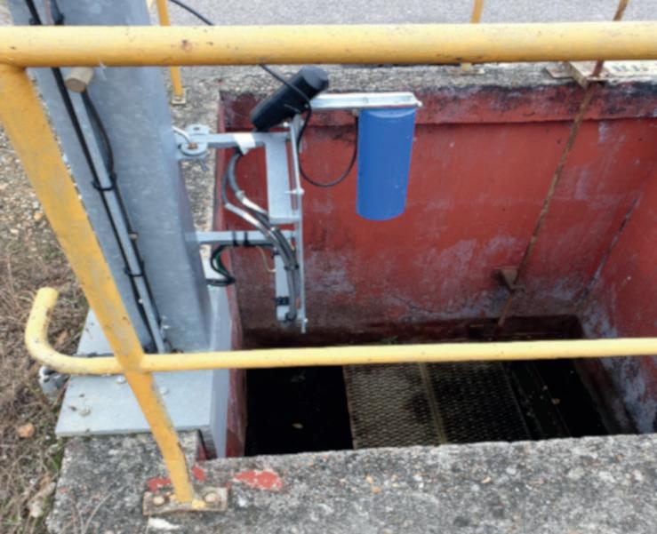
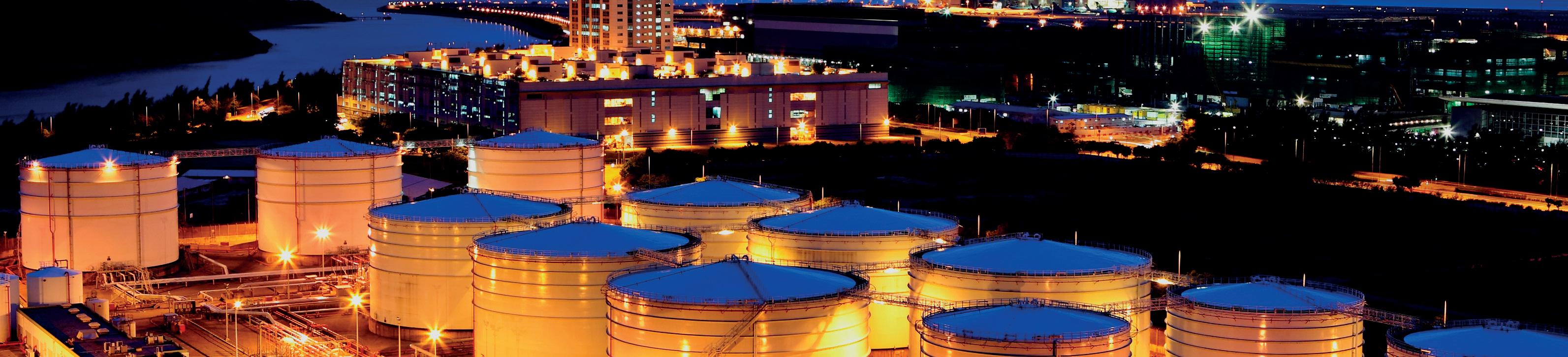 Figure 4. BlueHawk mounted on an aerial drone.

Paul Shields commenced his second tenure at Chart in 2009 and is currently the Marketing Director for Europe, focused on the company’s complete portfolio of cryogenic and compression products following last year’s acquisition of Howden. Paul has degrees in European Business & Management from Nottingham Trent University and the University of Paderborn.
01 How have recent geopolitical activities impacted the tank storage market?
Recent geopolitical activities mean there is far less certainty about pipeline natural gas and hence a greater reliance on imported LNG.
Of course LNG can be used to substitute pipeline gas but it also offers additional scope through the virtual pipeline, a model where LNG is transported to, and stored at, the point of use bringing natural gas to off-grid locations, enabling LNG to augment renewables, for example when the sun does not shine or the wind does not blow, and peak shaving.
02 What role will the tank storage sector play in the energy transition?
Cryogenic storage technology is fundamental to the virtual pipeline in the storage and transportation phase. As the import terminal at Klaipeda, Lithuania, demonstrates, small-scale facilities can play an important role in creating hubs for distribution of LNG. Storage capacity at Klaipeda is 5 x 1000 litre cryogenic ‘bullet’ tanks. All tanks are identical and shop-built. They were transported to site by surface transport and because total storage capacity is modularised, civil engineering and time at site is minimised, reducing project cost, complexity, schedule and risk.
LNG at terminals can be used for a number of applications: vaporised and injected into the pipeline; used at source for power generation, bunkering and vehicle fuelling; or loaded into cryogenic vessels for onward transportation. A cryogenic trailer is simply a cryogenic tank on wheels and cryogenic ISO containers facilitate multi-modal transport. The natural gas power station on Madeira island is a great example of the virtual pipeline in operation using ISO containers. LNG is loaded at the port of Sines and taken by road and sea to the island where full ISO containers are dropped and empty ones loaded onto the returning transport for refilling.
03 What additional challenges are associated with hydrogen storage and how can these be overcome? While much of what is needed to develop the hydrogen economy is new, novel or requires significant scale-up, liquid
hydrogen storage and distribution is already proven, safe and effective, with hundreds of hydrogen tanks already in operation around the world in industries such as manufacturing, science, research and aerospace.
The virtual pipeline model described previously for LNG is also applicable to hydrogen with liquid hydrogen trailers and ISO containers already developed and in operation.
04 How can your products and solutions support companies looking to decarbonise and/or optimise their operations?
Cryogenic storage can be a key element in helping companies to decarbonise. Even if they are not connected to the grid, the virtual pipeline enables business and communities that use diesel for power generation to switch to LNG, which is the cleanest burning fossil fuel.
Cryogenic products and technology are also source agnostic, hence tanks can store and distribute LNG, bioLNG and even mix the two. The model is virtually mirrored with hydrogen that can also be transported and stored at the point of use in liquid form.
Just as LNG and bioLNG are totally interchangeable or can be mixed, cryogenic storage and technology is also colour agnostic when it comes to hydrogen.
The Nexus of CleanTM is Chart’s business model for efficient use of liquid gases to improve sustainability, reduce waste and decarbonise across industry, energy, food and beverage, and water. Just a few examples of Chart technology at work in sectors people might not traditionally associate us with include the following. In the carbon capture field we have twin processes that can go beyond sequestration where captured carbon dioxide emissions are purified and liquefied for reuse, turning a waste stream into a valuable resource. Chart liquid nitrogen dosers are used in the packaging of a wide range of products including craft beers, baby formula and bottled water. As well as preservation, the pressurised nitrogen provides rigidity to the package, which means a reduction in the amount of plastic required. Howden compressor technology is used in the Air Lubrication System that blows micro bubbles under a ship’s hull, reducing the resistance between the hull and the water with fuel, and hence creates emissions savings of up to 10%.
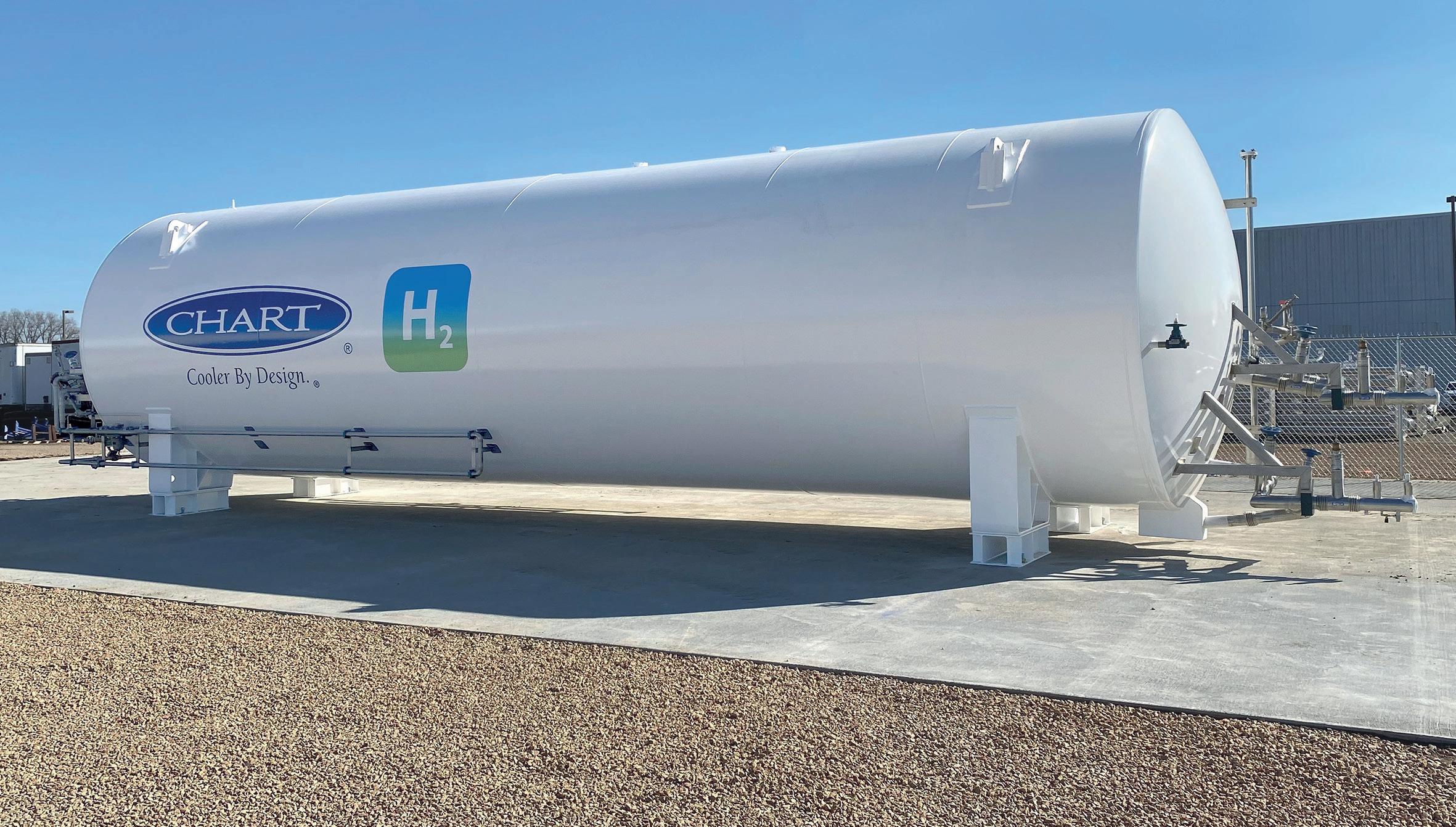
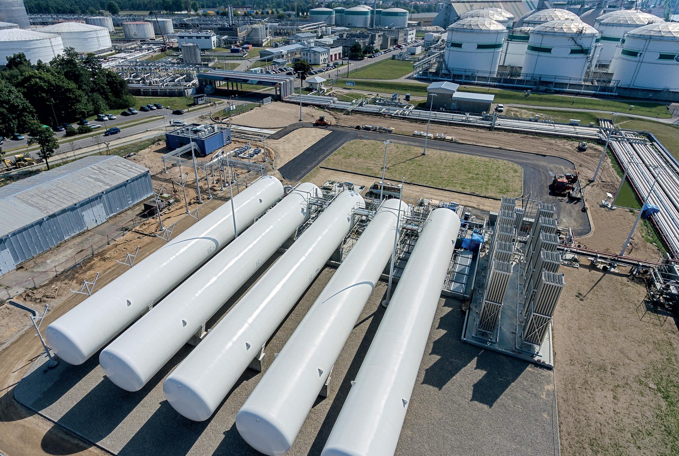
Chart cryogenic storage products are integral to the virtual pipeline facilitating increased energy independence and security through LNG and liquid hydrogen. By utilizing cryogenics to store gas in liquid form the tanks are much smaller than their gaseous equivalents. Cryogenic tanks are shop built and total storage capacity is modularized, reducing project cost, complexity, risk and timescale.


• Finance (D&B: 4A2 / Z-Score: 5.64)
• Safety (ZERO TRIR in 10 of 13 years)
• Change orders minimized
• Quality (Solutions and results)
• Schedules (On-time during COVID)
• Overhead reduced
Whether you are storing LNG, ammonia, or crude oil, contact an AT&V representative or office to realize ALL OF THE VALUE in your next project.