
April 2024

PROVEN PERFORMANCE TO HELP YOU PROVE YOUR COMMITMENT
OPTIMIZE OPERATIONS
SAVE ENERGY
REDUCE CO2 EMISSIONS
Struggling to save energy and lower CO2 emissions without compromising your operational performance?
Specified and used in over 50 LNG liquefaction and regasification projects around the world, Cryogel® Z insulation is helping owners and operators meet their targets.
Backed by our expertise, it’s our proven solution to solving your most challenging energy commitments.
Visit aerogel.com or contact us at info@aerogel.com

APRIL 2024
34 Flexible futures for island nations
Mark van Meel and Jürgen Essler, BRUGG Rohrsysteme GmbH, Germany, breaks down how the advent of stainless-pipes has altered small scale LNG for island populations.
39 Innovate under pressure
Ademiju Allen and Ole Dramdal, Rystad Energy, look at recent developments and upside in Canadian LNG.

High-pressure LNG fuel systems are an increasingly popular solution in shipping, and new innovative solutions are now being developed to meet the demand for leak-free fuel supply systems components with long service life. Rasmus Gregersen, Svanehøj, Denmark, provides a technical overview of one of these new solutions.
43 A focus on the behind-the-scenes
Clayton Kale, Director of Marketing, AMECO, USA, maps out an integrated site services approach for constructing LNG facilities.
46 Integrated operations
Rubén David Monje, Technology Services Consultant, KBC – A Yokogawa Company, discusses how integrated operations can optimise scheduling, production accounting and energy cost, and manage emissions on LNG sites.
50 Floating new ideas
Seatrium Ltd considers an alternative marine solution for small scale LNG.
55
Cathy Farina, General Manager Product Development, PolaireTech International Inc., and Aditya Hegde, General Manager, Polairetech India Private Ltd, explore how small scale LNG is gaining popularity in unlocking and commercialising local stranded gas resources, enabling a sustainable transition to cleaner energy. 10
Mark Butts and Yogesh Meher, CB&I, outline how identifying key risks can help optimise and de-risk projects from the very beginning.
Michael Pospisil P.E., Senior Engineer, and Rich Insull, P.E., Project Manager, Matrix PDM Engineering, detail the significance of life cycle analysis to helping secure LNG’s role in the future energy mix.
Dive into the intricate world of control valves and their role in LNG with Baker Hughes' article, 'Control valves and LNG: Common, yet critical.' Explore how control valves are essential in every stage of the LNG cycle, from liquefaction plants to transportation vessels and receiving terminals. Discover the diverse applications and types of control valves crucial for optimising operations, ensuring safety, and upholding the integrity of the LNG process.
ISSN 1747-1826 CONTENTS Copyright © Palladian Publications Ltd 2024. All rights reserved. No part of this publication may be reproduced, stored in a retrieval system, or transmitted in any form or by any means, electronic, mechanical, photocopying, recording or otherwise, without the prior permission of the copyright owner. All views expressed in this journal are those of the respective contributors and are not necessarily the opinions of the publisher, neither do the publishers endorse any of the claims made in the articles or the advertisements. Printed in the UK. ON THIS MONTH’S COVER LNG Industry is audited by the Audit Bureau of Circulations (ABC). An audit certificate is available on request from our sales department. CBP019982
Small scale LNG to the rescue
03 Comment 05 LNG news 14 Control valves and LNG: Common, yet critical Stephen
USA, addresses the
of control valves to the LNG supply chain. 19 Success through planning and risk mitigation
James, Baker Hughes,
importance
Securing LNG's leading role on the global energy stage
23
29 LNG loading equipment Q&A
Optimism on the horizon for Canadian LNG
LNG Industry asked several companies to discuss some topics regarding LNG loading equipment. 10

www.zwick-armaturen.de
*acc. to DIN EN 12266-1 100 % cOntrOL VaLVe 100 % tiGHt* tri-SHark
COMMENT
We’ve made it through 1Q24. The end of March, and the beginning of April, represents the end of Winter in the UK; hopefully, it will also bring some warmer (and drier) weather with it.
Daylight Savings started on 31 March this year, with the clocks ‘springing’ forward, signifying the start of longer days and lighter evenings in the Northern Hemisphere.
If more mild weather persists, as it has during January and February (the Met Office noted record UK temperatures for January 2024 and February 2024),1,2 it may be that the demand for LNG across Europe declines slightly. If this is the case, Europe will have to store any excess energy until it is needed. CB&I’s article, starting on p.19, looks at how identifying key risks can help optimise and de-risk LNG storage projects from the very beginning. The second part of this two-part article (coming in the June 2024 issue of LNG Industry) will address key early inputs and their impacts on the selection of optimal tank configuration.
March also saw what perhaps is the most prestigious film event of the year: the 96th Academy Awards. Americans emerged victorious: Oppenheimer was the standout success, winning seven awards, with Robert Downey Jr. winning Best Supporting Actor; Emma Stone won Best Actress for Poor Things; Da’Vine Joy Randolph won Best Supporting Actress for The Holdovers; and Billie Eilish and Finneas O’Connell came out on top for their Original Song, ‘What Was I Made For?’ from the blockbuster hit Barbie, to name a few.3
The US has also come out on top as the world’s largest LNG exporter in 2023, with US LNG exports averaging 11.9 billion ft3/d – a 12% increase (1.3 billion ft3/d) compared with 2022, according to data from the U.S. Energy Information Administration’s Natural Gas Monthly.4 Like 2022, Europe remained the primary destination for US LNG exports in 2023, accounting for 66% of US exports, followed by Asia at 26%.4

However, despite a large chunk of US LNG being exported to Asia (especially Japan and South Korea, which were the fourth and fifth-highest US LNG export volumes by country in 2023),4 only one US cargo reached Asia via Panama by 27 March 2024 according to S&P Global Commodity Insights data, with a record 24 US LNG cargoes choosing the longer route through the Cape of Good Hope as a result of long wait times and Red Sea tensions.5
Speaking of the US, make sure to keep an eye out for the 2nd edition of the North America supplement to LNG Industry, due to be published with the July 2024 issue. This special issue will look at recent trends and developments in the US, Canada, and Mexico, along with project case studies about various planned and active LNG projects. For now, make sure to read Rystad Energy’s regional report on Canada (p.10), which outlines recent developments in Canadian LNG.
References
1. ‘UK January temperature record, 28 January 2024’, Met Office, www.metoffice.gov.uk/binaries/content/assets/ metofficegovuk/pdf/weather/learn-about/uk-past-events/ interesting/2024/2024_03_jan_hightemp_scotland.pdf
2. ‘Warmest February on record for England and Wales’, Met Office, (1 March 2024), www.metoffice.gov.uk/about-us/press-office/ news/weather-and-climate/2024/february-2024-warm-and-wetfor-the-uk
3. ‘The 96th Academy Awards | 2024’, Oscars, (10 March 2024), www.oscars.org/oscars/ceremonies/2024
4. ‘The United States was the world’s largest liquefied natural gas exporter in 2023’, U.S. Energy Information Administration, (1 April 2024), www.eia.gov/todayinenergy/detail.php?id=61683
5. ‘US exports record number of LNG cargoes to Asia via Cape of Good Hope in March’, S&P Global Commodity Insights, (27 March 2024), www.spglobal.com/commodityinsights/en/ market-insights/latest-news/lng/032724-us-exports-recordnumber-of-lng-cargoes-to-asia-via-cape-of-good-hope-in-march
JESSICA CASEY EDITOR Editorial/Advertisement Offices, Palladian Publications Ltd 15 South Street, Farnham, Surrey, GU9 7QU, UK Tel: +44 (0) 1252 718 999 Website: www.lngindustry.com Managing Editor James Little james.little@palladianpublications.com Senior Editor Elizabeth Corner elizabeth.corner@palladianpublications.com Editor Jessica Casey jessica.casey@palladianpublications.com Editorial Assistant Théodore Reed-Martin theodore.reedmartin@palladianpublications.com Sales Director Rod Hardy rod.hardy@palladianpublications.com Sales Manager Will Powell will.powell@palladianpublications.com Production Designer Kate Wilkerson kate.wilkerson@palladianpublications.com Events Manager Louise Cameron louise.cameron@palladianpublications.com Digital Events Coordinator Merili Jurivete merili.jurivete@palladianpublications.com Digital Content Assistant Kristian Ilasko kristian.ilasko@palladianpublications.com Digital Administrator Nicole Harman-Smith nicole.harman-smith@palladianpublications.com Administration Manager Laura White laura.white@palladianpublications.com LNG Industry Subscription rates: Annual subscription: £50 UK including postage £60 overseas (postage airmail) Two year discounted rate: £80 UK including postage £96 overseas (postage airmail) Subscription claims: Claims for non receipt of issues must be made within 3 months of publication of the issue or they will not be honoured without charge. Applicable only to USA & Canada. LNG Industry (ISSN No: 1747-1826, USPS No: 006-760) is published monthly by Palladian Publications Ltd, GBR and distributed in the USA by Asendia USA, 701C Ashland Avenue Folcroft, PA 19032. Periodicals postage paid New Brunswick, NJ and additional mailing offices. POSTMASTER: send address changes to LNG Industry, 701C Ashland Ave, Folcroft PA 19032.
Turn to Cryodynamic Products for unequaled experience in marine services for LNG liquefaction, regasification, LNG carriers, and LNG bunkering.
Cryodynamics® cryogenic pumps and expanders have delivered maximum efficiency and reliabilty on hundreds of LNG vessels. With over 4,000 marine installations, and a focus on advancing LNG technologies, Cryodynamic Products is a partner you can trust. Who will you turn to?
n Learn more at www.elliott-turbo.com
n Contact us at: info@elliott-turbo.com

The World Turns to Elliott. COMPRESSORS | TURBINES | CRYODYNAMICS® | GLOBAL SERVICE
Japan
NYK and partners receive dual-fuel LNG bunkering vessel
A ceremony for the LNG bunkering vessel
KEYS Azalea was held at the end of March 2024 at the Yamatomachi Shipyard of Mitsubishi Shipbuilding Co., Ltd in Yamaguchi Prefecture to mark the vessel's delivery. Officials from KEYS Bunkering West Japan Corp. and Japan’s Ministry of Land, Infrastructure, Transport, and Tourism (MLIT) attended and prayed for the vessel's safe voyage.
KEYS, a joint venture established by Kyushu Electric Power Co., Inc., NYK Line, ITOCHU ENEX CO., LTD, and Saibu Gas Co., Ltd, will be the first to operate in the Kyushu and Setouchi areas.
KEYS Azalea will provide domestic coastal transport of LNG to consumers in the Kyushu and Setouchi areas and LNG bunkering for oceangoing vessels calling ports in the region. This is Japan's first LNG bunkering project to supply LNG to vessels in this vast area. The construction of the ship was funded by a subsidy adopted under MLIT’s FY2021 LNG Bunkering Base Formation Project.
KEYS Azalea is Japan's first LNG bunkering vessel equipped with a dual-fuel engine that can use both LNG and heavy oil as fuel for the main power generation system.
The four companies and KEYS will continue to contribute to reducing greenhouse gas emissions toward realising a carbon-neutral society.
Canada
LNGNEWS
Global TES partners with seven large international companies to create a global e-NG coalition
TES has entered into a memorandum of understanding with other large international companies to sponsor the creation of a global coalition, the e-NG Coalition, which is exclusively dedicated to electric natural gas (e-NG or e-natural gas), also referred to as e-methane.
The founding members of the e-NG Coalition include: Engie, Mitsubishi Corp., Osaka Gas, Sempra Infrastructure, TES, Tokyo Gas, Toho Gas, and TotalEnergies.
e-NG is a synthetic gas produced by the combination of renewable hydrogen and recycled carbon dioxide through methanation. With a molecular composition identical to conventional natural gas, it can be transported and stored utilising existing infrastructure. e-NG is considered a carbon-neutral ‘drop-in’ solution for gas consumers as it does not require the modification of industrial processes and applications to be used in place of conventional natural gas.
The e-NG Coalition will be a global platform to raise awareness on e-natural gas, promote global tradability and use of e-NG, foster policy support and harmonisation of applicable regulation and standards, and bolster collaboration across geographies and stakeholders along the e-NG value chain. Its purpose is to accelerate the development of e-NG in a reliable, affordable and sustainable way.
TC Energy to sell Prince Rupert Gas Transmission entities to Nisga’a Nation and Western LNG
TC Energy Corp. has entered into a binding letter agreement with Nisga’a Nation and Western LNG (the buyers) regarding the purchase and sale of all outstanding shares in Prince Rupert Gas Transmission Holdings Ltd and the limited partnership interests in Prince Rupert Gas Transmission Limited Partnership (collectively, PRGT). PRGT is a wholly-owned subsidiary of TC Energy and the developer of a natural gas pipeline project in British Columbia and potential delivery corridor that would further unlock Canada as a secure, affordable, and sustainable source of LNG.
As part of the letter agreement, TC Energy has committed to provide transition services, on a reimbursable basis, to facilitate the seamless transition of the pipeline project and support development work planned for this year. Subject to the execution of definitive agreements and customary closing conditions, the transaction is expected to close in 2Q24. Initial proceeds from the transaction are not expected to be material to TC Energy, with the potential to receive additional payments contingent upon the project achieving final investment decision and commercial operation.
April 2024 5

UAE
ADNOC signs second long-term heads of agreement for Ruwais LNG project
ADNOC has signed a 15-year heads of agreement with SEFE Marketing & Trading Singapore Pte Ltd, a subsidiary of Germany’s SEFE Securing Energy for Europe GmbH, for the delivery of 1 million tpy of LNG.
The LNG will primarily be sourced from ADNOC’s lower-carbon Ruwais LNG project, currently under development in Al Ruwais Industrial City, Abu Dhabi. The Ruwais LNG plant has been designed to run on clean power and will leverage the latest technologies and artificial intelligence tools to drive efficiency. This is the second long-term LNG supply agreement from the Ruwais LNG project, following the 15-year agreement with China’s ENN Natural Gas signed in December 2023. The deliveries are expected to start in 2028, upon commencement of the facility’s commercial operations.
USA
THE LNG ROUNDUP LNGNEWS
The Republic of Congo
Wison New Energies completes SPB tank lifting operation for Eni
Wison New Energies (WNE), witnessed by Eni and third-party partners, has hoisted the first SPB tank of the Marine XII Offshore FLNG project (Congo FLNG) into hull cargo hold space at WNE Nantong yard.
At 9:58 a.m. on 2 March 2024, following the cannon ignition, the SPB tank hoisting operation officially started. The SPB tank, designed and constructed by WNE, is the world's largest SPB tank. Its construction started in February 2023, with the upper and lower bodies of the tank closed in July, and completed overall installation on 2 March 2024. It is the core equipment of the Eni Congo LNG project. The entire tank is 45 m long, 44.9 m wide, with a main body height of 24 m and a total height of over 31 m. The tank has a volume of 45 000 m3, with a total weight exceeding 1400 t, making it the highest and largest independent lifting component in the entire project.
According to the plan, the Nantong yard was to complete the installation of the remaining three SPB tanks for the Congo LNG project by the end of March.
Glenfarne Energy Transition's Texas LNG announces LNG offtake agreement with Gunvor Group
Texas LNG Brownsville LLC, a 4 million tpy LNG export terminal to be constructed in the Port of Brownsville, Texas, and a subsidiary of Glenfarne Energy Transition, LLC, has signed a heads of agreement with Gunvor Group, through its subsidiary Gunvor Singapore Pte Ltd, for a 20-year LNG FOB sale and purchase agreement for 500 000 tpy of LNG from Texas LNG.
This news follows Texas LNG’s recently announced LNG tolling agreement with EQT Corporation. Texas LNG also recently announced partnerships with Baker Hughes, ABB, and Gulf LNG Tugs of Texas. These partnerships total nearly US$1 billion of investment into the project.
Glenfarne Energy Transition is the majority owner and managing member of Texas LNG. Texas LNG will achieve financial close and begin construction in 2024, commencing commercial operations in 2028.
X AG&P LNG awarded 20-year contract by PLN EPI
X MidOcean Energy completes acquisition of Tokyo Gas' interests in Australian LNG projects
X First ever bunkering operation completed at Hamina LNG

6 April 2024 Follow us on LinkedIn to read more about the articles www.linkedin.com/showcase/lngindustry
C M Y CM MY CY CMY K
Accelerating Modular LNG Solutions
Invisible. Invaluable.
Sometimes the things you can’t see make all the difference. Our integrated team of consultants, engineers, technicians, and construction professionals leverage our extensive history and expertise in mid-scale LNG technology and pioneering work in FLNG EPC to seamlessly bring our modular designs to life. Our modular LNG solutions enable fast-to-market results, so you can arrive at your destination on your terms, regardless of the technology, processes, or path.
The invaluable difference:
• Minimize interfaces and reduce prolonged onsite installation time and manpower
• Flexibility in compressor driver selection, cooling medium, and capacity from 1–2 MTPA per train
• Utilize the same modular philosophy for gas treating, heavies removal, product and boil-off handling
• Complete modular solutions for onshore and offshore applications between the pipeline and storage tank
bv.com/gas-solutions
LNGNEWS
30 April – 02 May 2024
2024 AGA Operations Conference
Washington, USA
www.aga.org/events/2024-aga-operationsconference-spring-committee-meetings
07 – 08 May 2024
ILTA 2024 Annual International Operating Conference & Trade Show
Texas, USA
https://ilta2024.ilta.org
07 – 09 May 2024
Canada Gas Exhibition & Conference
Vancouver, Canada
www.canadagaslng.com
13 – 16 May 2024
Asia Turbomachinery & Pump Symposium 2024
Kuala Lumpur, Malaysia
https://atps.tamu.edu
11 – 13 June 2024
Global Energy Show Canada 2024
Calgary, Canada
www.globalenergyshow.com
20 – 22 August 2024
Turbomachinery & Pump Symposia
Texas, USA
https://tps.tamu.edu
03 – 06 September 2024
SMM
Hamburg, Germany
www.smm-hamburg.com
17 – 20 September 2024
Gastech 2024
Texas, USA
www.gastechevent.com
Qatar
Saipem ships modules for North Field project
Saipem has shipped the first three topsides from Indonesia to QatarEnergy LNG’s North Field project in Qatar.
The first three topsides (one wellhead production and two riser platforms) were successfully loaded out from Saipem’s Karimun fabrication yard in Indonesia.
The modules are being installed on the northeast coast of Qatar for QatarEnergy LNG’s North Field production sustainability offshore and pipelines project, aimed at sustaining the production plateau of the largest non-associated natural gas field in the world.
Germany
Green light given for Germany's first land-based liquefied gases terminal in Stade
Hanseatic Energy Hub GmbH has committed to the final investment decision (FID) to construct Germany’s first land-based terminal for liquefied gases. After successfully concluding the permitting and commercial phase in late 2023, the company´s shareholders, Partners Group (on behalf of its clients), Enagás, Dow, and the Buss Group, have now successfully secured financing for the large scale infrastructure project, known as well as the Hanseatic Energy Hub (HEH). The globally active EPC specialist, Técnicas Reunidas and its partners, FCC and Enka, have been awarded the contract to build the future-flexible energy hub at the Stade Industrial Park. Around €1 billion will be invested in the construction of the terminal. The official groundbreaking ceremony is scheduled to be held in the coming weeks.
This FID allows the Hanseatic Energy Hub to make an important contribution to securing Europe’s energy supplies following its planned commissioning in 2027. Initially the HEH will serve as an import terminal for LNG, synthetic natural gas, and liquefied biomethane and, subsequently, for ammonia, as a carbon-neutral, hydrogen-based energy carrier. Once the HEH enters into service, the FSRU Energos Force chartered by Germany’s federal government, will set sail from Stade. The floating LNG terminal, which has been on site since March 2024, will continue to secure the gas supply in the short term until the more efficient land-based terminal is completed.
The Hanseatic Energy Hub will have a total capacity of 13.3 billion m3/y of natural gas. 90% of this volume has been booked long-term by three European energy majors EnBW, SEFE, and CEZ. The remaining capacity is reserved for short-term bookings. Long-term contracts include the option to switch to hydrogen-based energy carriers at a later stage. The terminal has been certified by permitting bodies as being ammonia-ready.
Following a development of more than six years, the Hanseatic Energy Hub project is entering its next phase. Enagás is providing the technical direction of the construction and will also be terminal operator. The Spanish energy company is increasing its share from 10 – 15%.
Johann Killinger, one of the entrepreneurs driving the project up to this point, is stepping down from the management team following the investment decision. He will now focus on his role as a shareholder, handing over to Jan Themlitz the CEO responsibilities for constructing and commissioning the terminal. Jan Themlitz has a long track record of developing energy-related projects as well as extensive LNG experience from having worked with gas majors and power generators for 30 years.
8 April 2024

Western Canadian dry gas is likely to see an oversupply of 1.97 billion ft3/d and 1.99 billion ft3/d this year and next, respectively, according to Rystad Energy research. This is inclusive of the LNG Canada Phase 1 ramp-up period, as the market requires incremental LNG capacity to provide balance to a market that is rapidly expanding short-term production. Rystad expects Western Canadian gas output to increase to 19.9 billion ft3/d in 2024 and to 21 billion ft3/d next year. Moreover, moderate growth is anticipated in local consumption, with a potential upside to gas-for-power demand. Aggregate flows from Western Canada are expected to decrease modestly to 8.34 billion ft3/d (-2.3% y/y), attributed to milder winter temperatures in the US, contributing to subdued regional gas demand. Even though Rystad sees an oversupplied

Ademiju Allen and Ole Dramdal, Rystad Energy, look at recent developments and upside in Canadian LNG.
Western Canada going forward, operators remain bullish on the Canadian natural gas price benchmark Alberta Energy Company (AECO). This is most likely associated with a less strained NOVA Gas Transmission Line (NGTL), as a greater volume of gas is being pulled westward with the Coastal GasLink. Furthermore, Alberta and British Columbia storage numbers remain elevated and will continue to do so without more takeaway capacity.
Western Canadian Sedimentary Basin (WCSB) output increased from 17.9 billion ft3/d in January 2022 to 19.4 billion ft3/d in January 2023. Throughout 2023, the output was reduced due to raging wildfires in both Alberta and British Columbia. In April, right before the wildfires started, WCSB dry gas output hit a record of 19.5 billion ft3/d before it plunged to 17.4 billion ft3/d for May. Subsequently, output climbed back
10

11
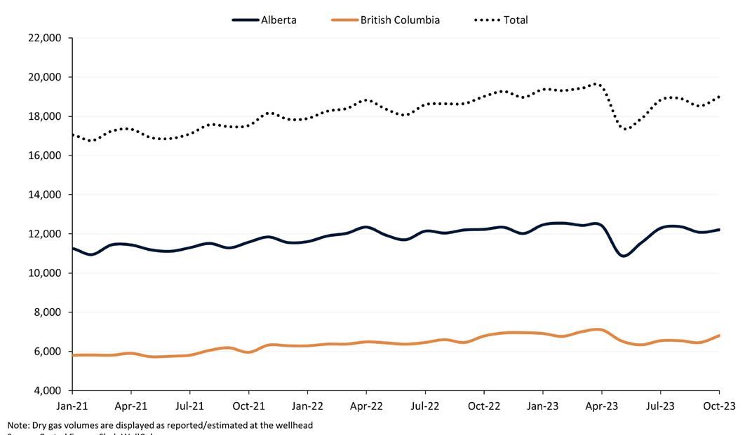
above 19 billion ft3/d in October, which is the last available data point for wellhead dry gas production.
Rystad Energy estimates full-year gas volumes in WCSB for 2023 will come in at 18.3 billion ft3/d. Going forward, Canadian operators’ bullish growth charge sees Rystad estimating 19.9 billion ft3/d this year, 21 billion ft3/d in 2025, and 21.9 billion ft3/d in 2026 – an output surge that nearly neutralises the new takeaway capacity.
Operators such as ARC Resources and Peyto Exploration & Development envision a structural upside to AECO prices. They are optimising their gas marketing strategies by exposing more of their gas production to the AECO hub ahead of LNG Canada’s estimated start-up. The notion in the industry is that LNG Canada will bring more stability to the AECO price. As mentioned, the implied production growth in dry gas is expected to cover the new capacity on the Coastal GasLink, leaving Alberta and British Columbia with the same oversupply in 2024 and 2025. Nevertheless, the upside for the AECO price may reside in fewer bottlenecks on the NGTL. With 2.1 billion ft3/d being shipped westward from the Basin, bypassing the need to route natural gas south through the constrained east and west gates, could result in less oversupply within the AECO hub.
Putting Canada on the global gas map
The Shell-operated LNG Canada Phase 1 is a pivotal project for the Canadian energy industry, as it is set to make the country a player in the global gas landscape. The operator recently announced the project was more than 85% complete and will begin start-up activities over the next 12 months. TC Energy also announced in November 2023 that the Coastal GasLink pipeline (2.1 billion ft3/d capacity) was mechanically complete ahead of its year-end target. The US$10.9 billion pipeline serves as a major link for growing yet-constrained basins such as the Montney. Rystad’s estimates indicate that the pipeline will begin to take in feed gas by 3Q24, with a seven-month timeline for the ramp-up to near full utilisation.
The industry is now firmly in the second wave of global LNG expansion, with demand expected to increase to 20 million tpy by 2030, and the bulk of the demand growth shouldered in Asia. Canadian LNG has an outsized opportunity to be part of this growth story and reap the economic benefits by increasing sanctioning efforts on the country’s west coast. Rystad Energy expects medium-term liquefaction capacity to expand to 20 million tpy in 2030, driven by west coast projects such as LNG Canada Phase I (14 million tpy), Woodfibre LNG (2.1 million tpy), and Cedar LNG (3 million tpy). The predominant driver of LNG demand lies in Asia, and the strategic proximity of these projects to the Asian market positions them competitively in comparison to other sources of North American LNG supply. However, a few speculative projects could present material upside to Canadian LNG supply surge, primarily LNG Canada Phase II, which could add another 14 million tpy. Nevertheless, Rystad’s base case does not anticipate liquefaction prior to 2030. The 12 million tpy Ksi Lisims LNG project showed signs of optimism recently as it signed a 2 million tpy offtake agreement with Shell. In aggregate, this would bring total Canadian LNG liquefaction capacity to 32 million tpy by 2030, a much-needed addition to
12 April 2024
global
Figure 1. Alberta and British Columbia monthly dry gas production (million ft3/d). Source: Rystad Energy ShaleWellCube.
Figure 2. Gas production in Western Canada (million ft3/d). Source: Rystad Energy UCube.
Figure 3. LNG Canada ramp-up. Source: Rystad Energy North America fundamentals dashboard; Rystad Energy R&A.
Figure 4. Medium-term Canada liquefaction capacity evolution (million tpy). Source: Rystad Energy GasMarket Cube.
LNG balances as Rystad Energy still anticipates a global deficit of 19 million tpy by 2030.
Woodfibre LNG officially commenced in 3Q23, with operations due to start in 2027. The 2.1 million tpy facility with floating storage tanks near Squamish in British Columbia will source gas from the Eagle Mountain – Woodfibre gas pipeline that is currently under expansion. Ksi Lisims, the floating LNG (FLNG) project proposed by the Rockies LNG partnership, formally applied for an environmental assessment certificate (EAC) from the British Columbia government in October 2023. For natural gas supply, Ksi Lisims has hired TC Energy to work on revised designs for the planned Prince Rupert Gas Transmission pipeline. Cedar LNG, the 3 million tpy FLNG facility, has progressed further over the last few quarters. The FLNG project secured environmental approval from the Government of British Columbia in March 2023, while securing the British Columbia regulator’s permit for the 8.5 km pipeline that will link the project to TC Energy’s Coastal GasLink Pipeline. Nevertheless, as Cedar LNG is projected to source gas from the Coastal GasLink pipeline and Woodfibre is expected to source gas from the Westcoast pipeline, takeaway capacity out of WCSB will remain at the same levels without expansions. Only Ksi Lisims’ Prince Rupert Pipeline will add significant takeaway capacity.
Looking forward
In the last 12 – 18 months, cost inflation has been a significant factor influencing capital deployment in the energy sector and is even more relevant to large CAPEX projects such as liquefaction facilities. Figure 5 analyses normalised CAPEX investments for
the planned Canadian LNG export facilities, indicating that both phases of the LNG Canada project are near or above US$1000/t. CAPEX for Phase I of LNG Canada has grown materially since the project was first announced, and estimates on the chart do not include the midstream cost i.e. construction of the pipeline. Currently, Rystad estimates expect normalised cost of US$928/t for LNG Canada Phase II, and absolute CAPEX at US$13 billion. CAPEX estimates for other projects are subject to significant variability as development plans are in the early stage. However, Rystad is confident in the US$1.4 billion estimates for Woodfibre LNG project. Project economics will drive the final investment decision for Ksi Lisims LNG export project; Rystad’s estimates indicate CAPEX of US$10 billion, but the regulatory seems to be slower than anticipated which could force increases.
BOG management for Maritime LNG
Two concepts: Direct Reliquefaction or Subcooling


• Plug and play modular design
• Turn-key projects
• Cost efficient redundancy to meet uptime requirement
• Energy efficient Stirling cycle
• Small footprint 1.6 sqm (17,2 sqft) per unit Stirling Cryogenics +31 40
Figure 5. Normalised Canada liquefaction investment by facility phase (US$/t). Source: Rystad Energy GasMarket Cube.
77 300
26
info@stirlingcryogenics.com www.stirlingcryogenics.com
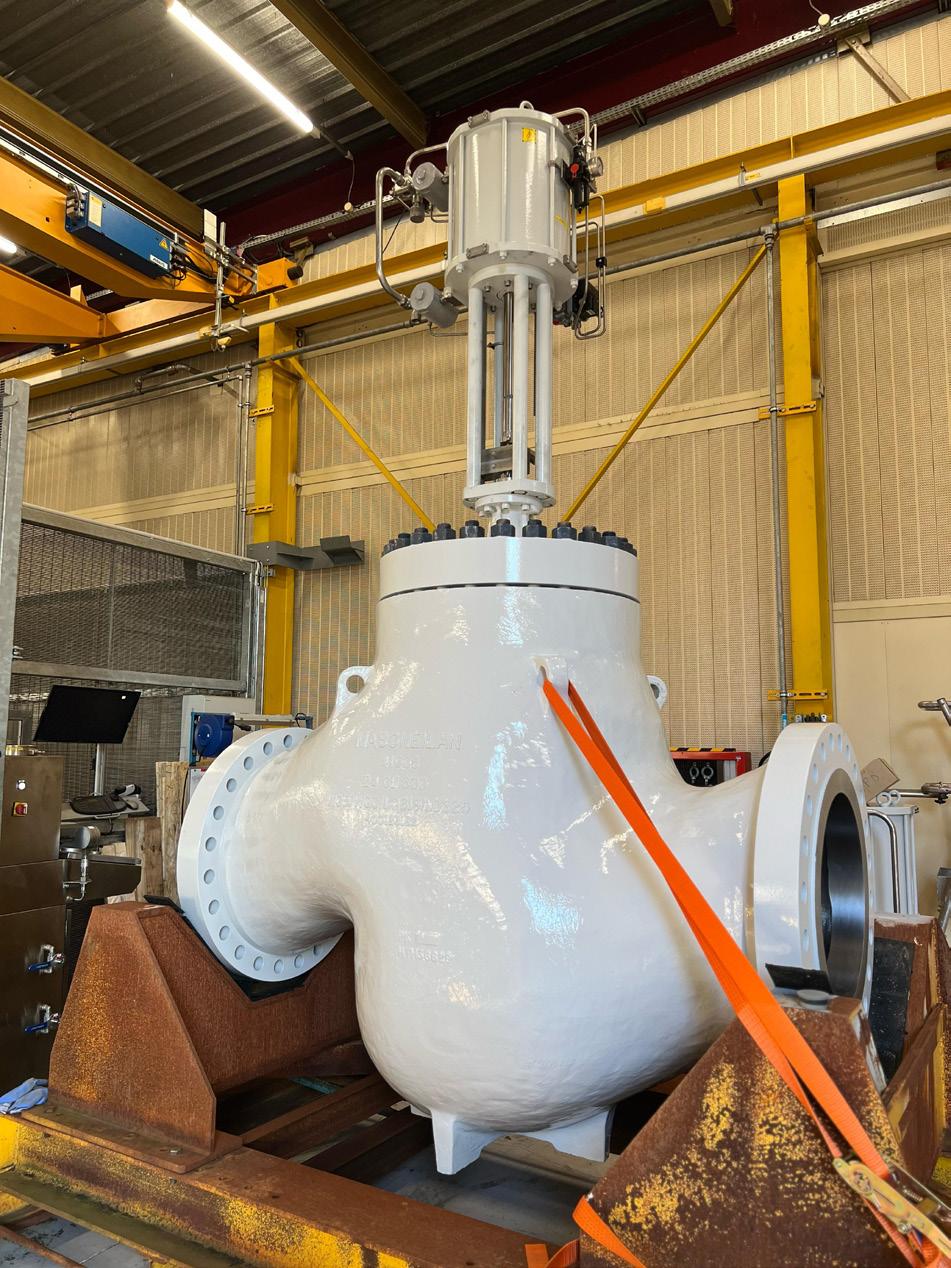
Stephen James, Baker Hughes, USA, addresses the importance of control valves to the LNG supply chain.
Control valves and LNG: Common, yet critical
The LNG industry stands as a cornerstone in the global energy landscape, with control valves serving as indispensable components in its supply chain. The journey of LNG entails numerous stages, each necessitating precise control and regulation of fluid flow. Control valves emerge as essential elements, enabling efficient operations and maintaining safety standards across LNG liquefaction plants, transportation vessels, and receiving terminals. Understanding

the diverse applications and types of control valves in the LNG industry is paramount for proper control valve selection and long-term operational reliability that optimises operations and upholds the integrity of the various steps in the LNG process.
LNG liquefaction
LNG liquefaction is a complex and pivotal process within the LNG supply chain, serving as the foundation for the entire
14
industry. This process occurs at LNG liquefaction plants, strategically located near natural gas reserves or major pipeline networks. The primary objective of LNG liquefaction is to convert natural gas from its gaseous state to a liquid form, enabling efficient transportation and storage. This transformation involves several intricate steps, each requiring meticulous control and regulation, with control valves playing a crucial role in ensuring the smooth operation and safety of the liquefaction process.

At the heart of LNG liquefaction is the need to reduce the volume of natural gas while maintaining its energy density, making it economically viable for long-distance transportation. This reduction in volume is achieved through the application of cryogenic temperatures, typically around -162˚C (-260˚F), at which point natural gas transitions into a liquid state known as LNG.
The liquefaction process can be broadly categorised into three main stages: pretreatment, refrigeration, and condensation.
15
During the pretreatment stage, raw natural gas undergoes purification to remove impurities such as water, carbon dioxide (CO2), and sulfur compounds (H2S). This purification step is essential to prevent corrosion and contamination within the liquefaction equipment. Specialised control valves with unique material combinations are utilised in the pretreatment stage of the LNG plant. During this phase it is common to remove CO2 and H2S with an amine contactor. The letdown valve at the bottom of the amine contactor needs specially selected materials such as duplex stainless steel or high nickel alloys to
combat corrosion from the process fluid. In addition to the material selection, a proper valve design will utilise multi-stage trim to prevent cavitation and also have a gradual expansion in the trim flow area to prevent choking due to off-gassing during the pressure reduction. The result is a specially engineered valve suitable for the rigours of the application: corrosion, cavitation, and off-gassing.
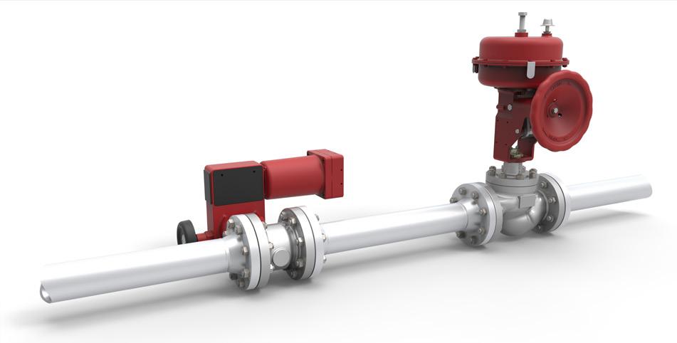
Once purified, the natural gas enters the refrigeration stage, where it is cooled to cryogenic temperatures using a series of refrigeration cycles. These refrigeration cycles rely on the use of cryogenic refrigerants, such as propane or ethylene, to achieve the required temperature reduction. Control valves are deployed throughout this stage to regulate the flow of refrigerants, control pressure levels, and maintain precise temperature conditions within the liquefaction equipment. Some of the most critical control valves in this stage are those associated with turbomachinery protection. Compressor anti-surge control valves modulate flow to protect compressors from surge conditions that could lead to equipment damage or failure, safeguarding the integrity of the LNG trains. The compressor anti-surge valve is high capacity while also having very fast opening and response times, typically no more than 1 – 2 secs. Due to the high pressure drop ratios of the application, noise and vibration need to be mitigated using advanced valve trims based on pressure drop staging, frequency shifting and velocity management. High rangeability, often more than 100:1, is also required for when the valves are used at low capacity during compressor start-up. The cumulative requirements lead to specific valve designs tailored to each piece of turbomachinery.
The final stage of the liquefaction process involves the condensation of the cooled natural gas into LNG. This condensation occurs within specialised equipment, where the natural gas is subjected to low temperatures and high pressures, causing it to transition from a gaseous to a liquid state. Control valves play a crucial role in this stage, facilitating the precise control of flow rates while ensuring optimal pressure conditions. One of the most critical control valves in this part of the plant is the turboexpander bypass valve, or Joule-Thompson (J-T) valve. This valve needs to be suitable for low cryogenic temperatures while utilising specially designed multi-stage trims to safely manage the J-T phase change without excessive, damaging vibration. Special consideration needs to be made to the J-T valve, so it is sufficiently large for low inlet and outlet valve velocities.
Several types of control valves are commonly used in LNG liquefaction plants, each tailored to meet specific operational requirements and environmental conditions. Among these are triple offset butterfly valves, eccentric rotary control valves, and specialised cryogenic control valves. Triple offset butterfly valves offer precise flow control and tight shutoff capabilities, making them well-suited for cryogenic applications where leakage prevention is paramount. Eccentric rotary control valves provide precise control in a more compact and sustainable design than conventional globe control valves and are ideally suited for managing many general service processes within LNG liquefaction plants. Specialised cryogenic control valves are specifically designed to operate reliably in extremely low temperatures, ensuring the safe and efficient handling of LNG throughout the liquefaction process.
Sustainability is a key consideration in the design and operation of LNG liquefaction plants, with a focus on
16 April 2024
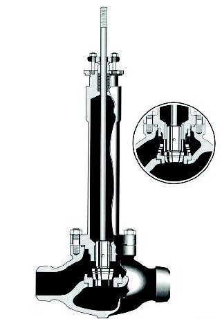
Figure 1. Multi-stage anti-cavitation valve with customised trim used in acid-gas removal systems.
Figure 2. Compressor anti-surge control valves couple large capacity with precise, high-speed control.
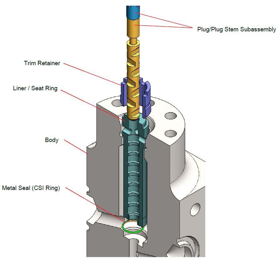
Trim Retainer Liner/Seat Ring
Body
Metal Seal (CSI Ring)
Plug/Plug Stem Subassembly
Over A Century of Proven Control Valve Performance
Optimized with advanced digital instrumentation for industry leading safety and efficiency
Innovative technical solutions to meet the world’s most challenging process control applications
Trusted reliability on critical components in the harshest environments
more information, contact your local Baker Hughes representative or visit valves.bakerhughes.com
For
© Copyright Baker Hughes company. All rights reserved
Masoneilan... Process Controlled.
minimising energy consumption, reducing emissions, and maximising operational efficiency. Sustainable practices encompass various aspects of plant design and operation, including the selection of energy and material efficient control
valves that are certified for low fugitive emission operations. To ensure proper selection of sustainable valve designs, a plant designer or operator should be mindful of valve mass (the lower, the better) and compliance to fugitive emissions standards like ISO 15848, in addition to anticipated long service life for the selected application. Control valves play a crucial role in these efforts, as they directly influence the efficiency and reliability of LNG liquefaction processes.
LNG transportation
Following liquefaction, LNG is transported from production facilities to receiving terminals using specialised LNG carriers. The transportation of LNG requires meticulous management of flow, pressure, and temperature to ensure the integrity of the cargo and the safety of the vessel and crew.
Control valves play a critical role in LNG transportation, regulating the flow of LNG within the carriers. In addition to operating successfully as a control valve, they also need to be properly certified for use on a marine vessel and suitably designed for the extreme environments found at sea. Control valves found topsides of LNG tankers are commonly designed with specialised stainless-steel enclosures around critical control components to maintain their integrity at sea.
LNG receiving terminals
LNG receiving terminals are facilities where imported LNG is received, stored, regasified, and distributed for various applications, such as power generation, heating, and industrial processes. The primary purpose of LNG receiving terminals is to convert LNG back into its gaseous state for use in end-user applications.
The regasification process at LNG receiving terminals involves heating the LNG to return it to its gaseous state. This is typically accomplished using heat exchangers or vaporisers, where the LNG is warmed by exchanging heat with seawater, ambient air, or other sources of heat energy.
Control valves play a crucial role in LNG receiving terminals, regulating the flow of LNG during regasification, controlling pressure and temperature, and ensuring the safe and efficient distribution of natural gas to consumers. Control valve applications in an LNG terminal vary widely. One unique application in LNG terminals is that of high pressure, multi-stage, anti-cavitation, cryogenic control valves for LNG pump recirculation. The combination of high pressure, high-pressure drop ratio, and cryogenic operating temperatures results in this unique control valve design rarely found outside of this industry.
Summary
Control valves are indispensable components in the LNG supply chain, playing a crucial role in ensuring the safe and efficient operation of LNG liquefaction plants, transportation vessels, and receiving terminals. Ranging from tight shut-off triple offset butterfly valves, to high-speed compressor anti-surge valves, to specialised cryogenic control valves, control valves enable precise control of flow, pressure, and temperature throughout LNG processes. Optimal valve selection balances proper valve suitability, sustainability, and long-term operability. Control valves are common, yet highly critical pieces of equipment needed by LNG operators to enhance the reliability, safety, and sustainability of their operations, contributing to the continued growth and success of the LNG industry.
18 April 2024
Figure 3. Specialised control valves with custom trims are designed to function optimally at cryogenic temperatures commonly found in LNG.
Figure 4. Selection of advanced eccentric rotary control valves can provide a more sustainable solution with significant material reduction vs conventional globe control valves.
Figure 5. Control valves installed on LNG tankers need to be designed and certified for installation in the harshest of marine environments.
SUC ESS THROUGH PLANNING AND RISK MITIGATION
Mark Butts and Yogesh Meher, CB&I, outline how identifying key risks can help optimise and de-risk projects from the very beginning.

In today’s LNG industry, safety considerations are paramount, as underscored by the degree to which related regulations, industry design codes, equipment, procedures, and systems permeate the entire LNG value chain. Modern LNG tank designs have many built-in features which act as safeguards and provide layers of protection against the identified risks.
There is more than one means to contain liquid and vapour in an LNG tank. In fact, the industry has standardised several configurations, such as single
19
containment and full containment. Operational integrity of LNG facilities relies on the foundation set in codes and standards that dictate engineering designs and material specifications for constructing storage tanks and related equipment. These guidelines serve as a crucial layer of protection, ensuring facilities maintain safe containment of LNG, thus allowing companies to mitigate risks, safeguard personnel, and uphold reliable operations. In the full containment configuration, the secondary containment serves as an additional layer of protection against potential leaks or spills, providing a safeguard in the event of primary liquid containment failure. The secondary container is engineered to prevent the spread of LNG beyond the primary area, either by installing a barrier (such as a dike or berm), or alternatively by utilising an outer tank surrounding the inner tank, which can also be designed to contain the vapour and the liquid.
The selection of a tank system’s configuration has a significant impact on the facility siting. Facility codes such as NFPA 59A (Standard for the Production, Storage, and Handling of Liquefied Natural Gas) have siting requirements, including separation distances from the storage tank to the facility property lines, that are dependent on the selected tank system concept,
e.g. single, double, or full containment system. A full containment tank system allows the most compact facility siting and land utilisation, since the secondary container serves as an impoundment for both LNG liquid and vapours in case of a primary liquid container leak.
Plot size available for construction and siting of the facility are important factors for engineering design and constructability. Process design requirements (such as flow rates, operating pressures, etc.) must also be considered, as well as local regulations established by the Authority Having Jurisdiction (AHJ), community, state, or country. Finally, industry codes and standards establish important requirements for any project.
CB&I’s project delivery model ensures high-quality and cost-effective solutions for projects. Many customers draw on the company’s deep knowledge and extensive LNG experience early in a project’s development, allowing us to provide input, recommendations, and project-specific solutions that enhance the long-term value of the facility. Its integrated EPC resources enable us to self-perform all aspects of the project, from conceptual design to tank commissioning. This translates into low-risk and high-value LNG storage solutions for the company’s customers.
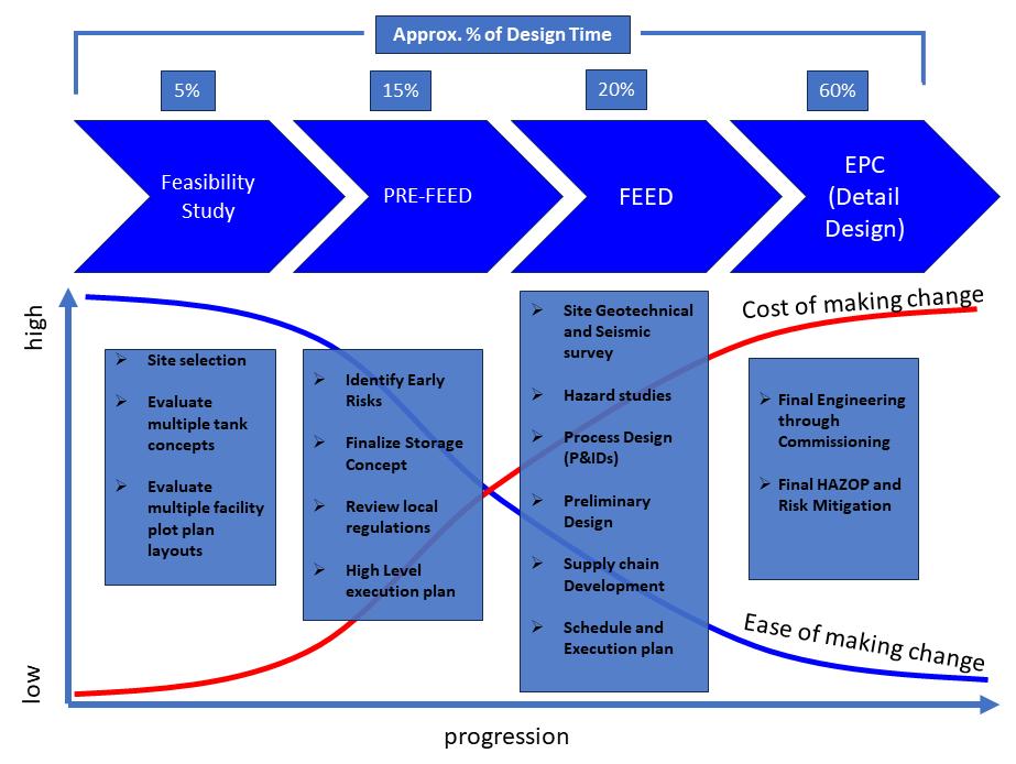
Early engagement: A key to success
Early involvement of a storage EPC contractor and open collaboration between the contractor and owner opens more opportunities to explore innovative approaches and select the optimal design and in-built safeguards. Late engagement of the contractor often results in additional cost and longer schedules due to missed opportunities to influence early decisions that shape the project development and execution.
Early engagement also offers more opportunities to explore innovative approaches to material selection, supply chain, construction methodologies, and commercial models in partnership with customers. This is more important than ever with the recent rising global costs impacting all aspects of the EPC project lifecycle. By prioritising early engagement, CB&I supports customers by providing lower cost and shorter time to market on storage solutions.
Terms like engineering study, FEED, pre-project planning (PPP), front end loading (FEL), feasibility analysis, and early project planning are often used interchangeably, reflecting various stages of project development. An engineering study typically involves an analysis of project requirements, feasibility, and preliminary design options. FEED, on the other hand, goes deeper into the engineering phase, refining concepts and providing detailed designs and cost estimates. PPP encompasses the initial stages of project development, focusing on defining project scope, objectives, and requirements. While FEL emphasises early project planning, aiming to minimise risks and uncertainties before full scale project execution. These terms collectively represent the iterative process of project development, from initial concept to detailed design and planning. The LNG storage tank capacity, configuration and containment
20 April 2024
Figure 1. Continuous improvement of LNG storage safety.
Figure 2. Early engagement is a key to success.
EVERYTHING UNDER ONE ROOF

ATMOSPHERIC PRESSURIZED
LOW TEMPERATURE
CRYOGENIC TERMINALS


www.cbi.com
type are typically finalised during these phases of early engagement. Some key activities include finalisation of the facility layout and plot plan, thorough geotechnical investigation, a preliminary process design, and facility hazard risk assessment.
Early risk assessment helps with de-risking
Today’s LNG storage design has many built-in safeguards to handle a variety of loadings, hazards, and upset conditions during its operating life. These built-in design features are often identified as safeguards during a facility hazard assessment (HAZOP and HAZID). Early and detailed planning provides definition of key design inputs, which are then implemented to optimise the design and maximise the safeguards required to build a more robust structure, facilitating many years of successful operation.
Industry codes for LNG tanks require the purchaser to conduct a risk assessment and consider it in the selection of the storage concept and configuration. All credible release events and the potential for event escalation need to be considered during the risk assessment.
A Hazard Risk Assessment is typically part of the FEED design and begins with identifying the internal (inside-out) and external (outside-in) hazards which have a direct impact on the design of the LNG tank. Internal hazards are typically tank overfill, thermal shock, leaks, overpressure, vacuum, and rollover. These are often mitigated using additional layers of protection in the form of redundancy and early detection.
External hazards play a significant role in the selection of the tank containment system and materials of construction. The various external hazards can affect a tank system and may require consideration in the facility risk assessment. Major external hazards – such as external fire, external explosion, and projectile impact – should always be included in the facility risk assessment performed by the facility owner. Seismic (earthquake) loading, while being considered as an external hazard, is more applicable to the primary tank due to the greater mass of the stored liquid.
The risk assessment helps determine the credibility of these hazards and magnitude of external loads and effects these hazards apply to tank systems. While the storage system’s outer tank is often constructed of

Worldwide Coverage
pre-stressed concrete to mitigate these external hazards, in some cases an outer steel tank may be adequate.
An overall outline of risk assessment includes the following:
z Identifying the hazards.
z Identifying potential release events and scenarios.
z Evaluating probability of occurrence of events.
z Estimating consequences (impacts to people, property and environment).
z Evaluating resulting risks.
A Project-Specific Hazard Assessment includes assessing the probability of occurrence of the hazard and evaluating the degree of damage from the hazard loading.
Conclusions
A comprehensive storage EPC execution plan, coupled with early engagement between the EPC contractor and the owner during project development, allows for the identification of key inputs and risks, thereby optimising and de-risking the project from its outset. This proactive approach enhances project efficiency, minimises uncertainties, and ultimately improves the likelihood of successful project delivery.
Since constructing its first LNG tank in the 1950s, CB&I has focused on delivering LNG storage solutions safely, on time, and with the highest quality standards. The industry draws on CB&I’s deep knowledge and extensive LNG experience early in a project’s development, allowing the company to provide input, recommendations, and project-specific solutions that deliver greater long-term value. The ability to self-perform all aspects of the project, from conceptual design to tank commissioning, translates into low-risk and high-value LNG storage solutions for the company’s customers.
The second part of this two-part article series in the June 2024 edition of LNG Industry will address key early inputs and their impact on the selection of the optimal tank configuration. The company will also address risk detection and mitigation measures which help provide additional safeguards.
A global industry requires a global publication
For the latest LNG industry news visit: www.lngindustry.com

Michael Pospisil P.E., Senior Engineer, and Rich Insull, P.E., Project Manager, Matrix PDM Engineering, detail the significance of life cycle analysis to helping secure LNG’s role in the future energy mix.
As the world continues to focus on reducing greenhouse gas (GHG) emissions, it must also manage increasing demands for reliable energy. Against this backdrop, LNG remains centre stage in the evolving energy transition. The use of LNG reduces GHG emissions while also nearly eliminating other toxins such as sulfur oxide (SOX)
23
and nitrogen oxide (NOX). As such, it is the fuel of choice for diesel replacement in heavy horsepower applications. LNG is also a critical lower carbon solution that helps ensure reliable power for electricity, heating, and cooling in remote areas or during periods of peak demand, such as extreme weather events.
Given its leading role, the inspection, maintenance, and repair of LNG tanks and terminals is vital to providing energy assurance through safe, ongoing operation. Ideally this work, referred to as life cycle analysis (LCA), is completed as part of a planned lifecycle infrastructure asset management programme for a facility, but it can sometimes be triggered because of unplanned events.
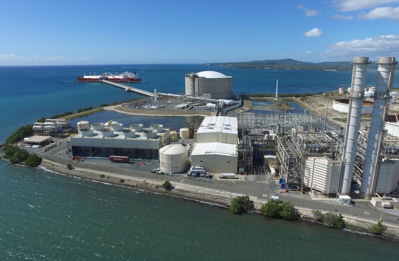
A real-world example
In January 2020, a series of earthquakes rocked the island of Puerto Rico, with the most significant being an M6.4 event that originated within 13 km of the EcoEléctrica LNG import terminal and power plant. A critical energy resource, the facility supplies natural gas fuel to produce up to 40% of the island’s total power, and its natural gas combined cycle power plant is the cleanest, most reliable source of energy for the island.
Seismic monitoring instrumentation on the EcoEléctrica tank indicated ground shaking caused by the M6.4 event produced accelerations on the structure that exceeded the seismic hazard developed for the original design.
As a result, EcoEléctrica was tasked with responding to multiple inquiries from US regulatory bodies including the Federal Energy Regulatory Commission (FERC), Department of Transportation Pipeline and Hazardous Materials Safety Administration (PHMSA), U.S. Coast Guard (USCG), and U.S. Geological Survey (USGS). In question were the short-term and long-term risks associated with the facility’s 160 000 m3 double-containment LNG storage tank.
For answers, EcoEléctrica turned to Matrix PDM Engineering, whose engineers possess extensive expertise in cryogenic tank design, and whose predecessor firm had designed, fabricated, and erected the EcoEléctrica tank when it was commissioned in the early 2000s.
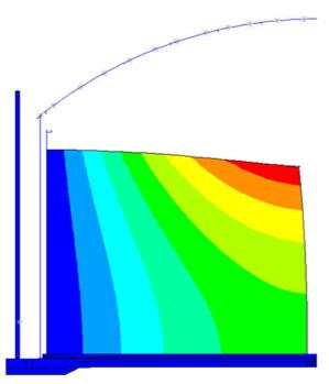
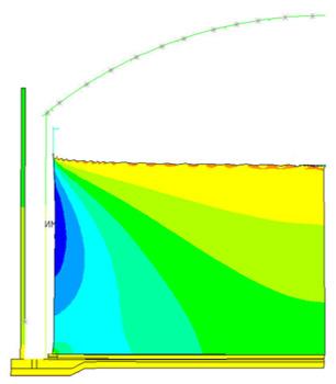
Matrix conceptualised the problem and developed the methodology for the tank analysis considering input from engineering seismologists, EcoEléctrica, and technical staff at regulatory agencies. The Matrix engineering team conducted multiple seismic and structural analyses on the tank system; the first was a forensic analysis following the M6.4 event. This analysis consisted of a desktop study for the seismic and structural analysis of the tank for accelerations developed from the ground motion recorded during the M6.4 event. The team was able to verify that the tank system remained undamaged during the M6.4 event and was safe for continued operation. Sample results for modal response spectrum analysis of the fluid structure system can be seen on the left in Figure 2.
Additionally, regulatory agencies implemented restrictions on the liquid level inventory until EcoEléctrica could satisfy concerns for plant and public safety due to potential increases in short and long-term seismic hazards because of the M6.4 event. The Matrix team performed multiple seismic and structural analyses for seismic hazards including those developed based on current standards, as well as potential hazards developed to consider elevated return periods. Several of the evaluations considered seismic hazards beyond what is currently required by US LNG codes, including 49 CFR Part 193.
Ultimately, the LNG tank and its prestressed concrete secondary container were deemed to have performed safely during the M6.4 event. The analysis was also used to support regulatory approval for liquid level that the facility could use for continued operation.
Planned LCA
While an unplanned event resulted in the LCA performed at EcoEléctrica, given LNG’s role in achieving global energy goals, planned LCAs should be a priority with today’s owner/operators – especially with ageing facilities – to ensure their facility’s safe, continued operation and compliance with changing regulations. In the US alone, there are 107 active LNG facilities (excluding mobile, temporary, and satellite facilities), 70 of which were constructed between 1965 – 1995, according to PHMSA. The remainder of this article presents a structured approach for performing an LCA on the cryogenic storage systems at these facilities, whether double-wall, single, or full containment.
While assessment methodologies are similar for different tank systems, each tank has its own characteristics and requires a facility-specific process. The complexity requires that all phases of an LCA be carefully planned and executed.
Phase 1: Data collection
Assessment begins with collection of information such as:
z Past tank loading and unloading cycles.
z Design calculations.
z Design and fabrication drawings.
24 April 2024
Figure 1. EcoEléctrica LNG import terminal and power plant, a critical energy resource, that supplies up to 40% of the island’s total power, and is its cleanest, most reliable source or energy, impacted by an M6.4 earthquake in early 2020.
z Construction documentation (including material certificates, material test reports, and weld procedures).
z Geotechnical reports, commissioning, operation, maintenance, repair, and modification records.
Certain facility operating information is also necessary, such as transport logs, which indicate loading/unloading information, temperature data, foundation settlement information, and historical tank vapour pressure information.
The operating history and anticipated past and future loading cycles form the basis for a fit for service (FFS) and remaining service life (RSL) assessment.
Assumptions based on historical data of similar facilities and experience may be made if there are gaps in facility data or operating information.
Understanding the owner’s objectives is critical to this phase, as this will significantly influence the work required in Phases 2 and 3. A longer life expectancy, for example, will require closer evaluation and potentially more repairs. Similarly, if Phase 2 analysis results in a long future life, the work in Phase 3 can be minimised.
Phase 2: Desktop study
The desktop study involves data review and integration, tank stress and fatigue analyses, identification of critical
areas to inspect and validate assumptions or fundings, development of procedures to enable tank entry, inspection, repairs, and closure. Phase 2 also includes planning and scheduling activities.
Typical assessments are iterative, with various methods applied. The assessment is focused on highly stressed, fatigue-sensitive components of the inner tank, and covers aspects such as the foundation, insulation, penetrations, and platforms.
Critical components of the inner tank include the circumferential weld of the shell to the annular plate, shell penetrations, and circumferential lap weld of the
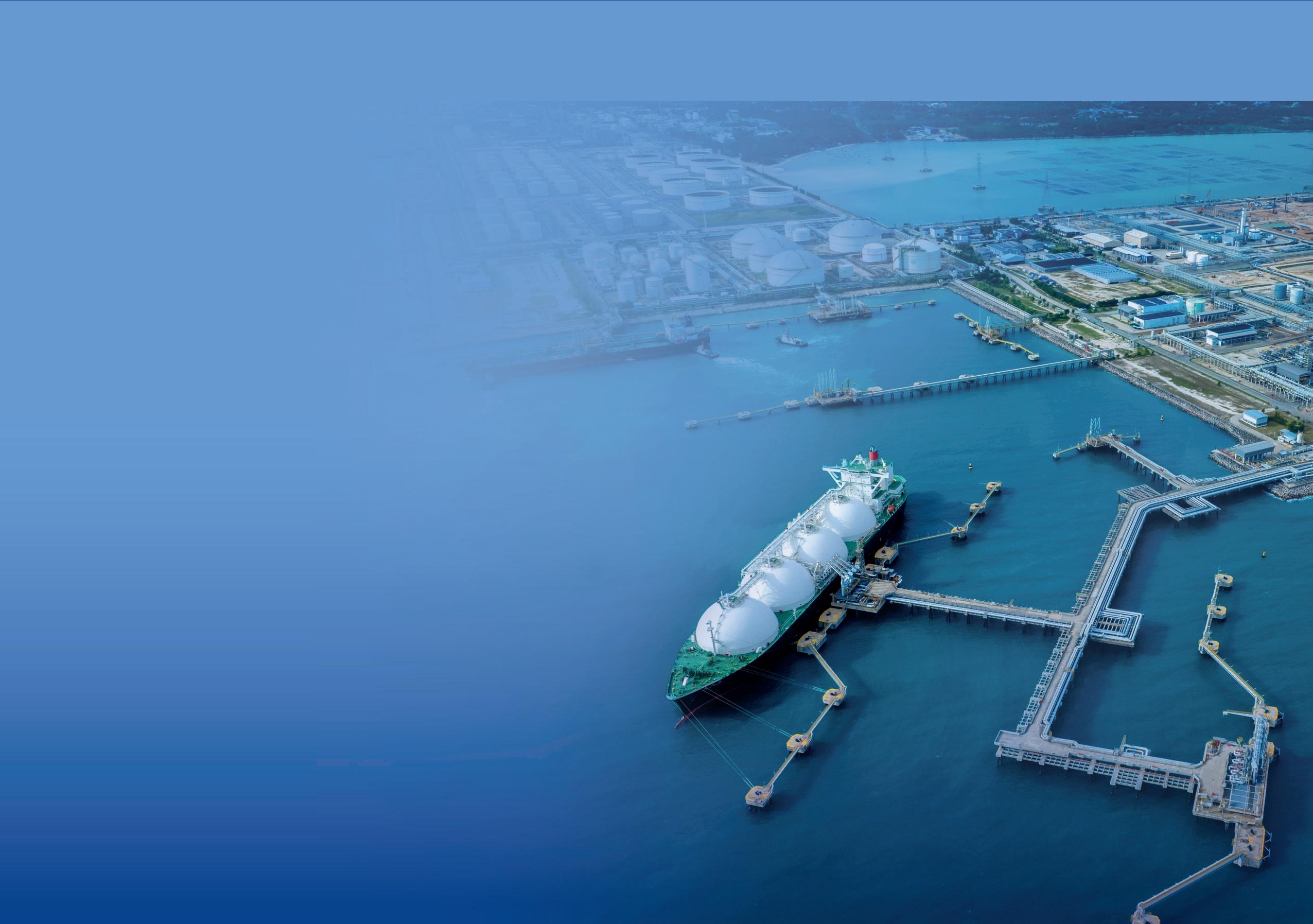 Figure 2. The fundamental fluid structural modal response (left) and the fundamental sloshing liquid modal response (right).
bottom plate to the annular plate. Underpinning the assessment are:
z Finite element analyses (FEA) to identify regions that are susceptible to fatigue.
z Fatigue analyses using crack growth models and damage accumulation mechanisms to estimate consumed and remaining design life.
The spectrum of topics covered is vast, and a complete depiction of the entire analyses is impractical. Therefore, only a few items are presented here.
A key issue in FEA modelling is the need to correctly mimic the as-built conditions to accurately depict peak stresses.
Another issue is geometric stress concentration factors (SCFs). Occasionally, the FEA model and mesh size is not adequate to model the peak stresses. In such cases, SCFs can be utilised to properly depict the values. The SCFs are based on published literature and experience of the analyst.
Fatigue is the driving mechanism in an LCA evaluation, as tanks are continually loaded and unloaded. Due to repeated or fluctuating stresses, pre-existing minute cracks in material grow. A fatigue sensitive component will fail when these cracks propagate to a level that cannot be sustained.
Two approaches can be used for fatigue. The first is an S-N Curve approach, where there is a finite number of cycles at a stress range at which a component fails. These curves exist for both smooth bar specimens and welded joints. For a specific joint under consideration:
1. Stress ranges are determined using loads in a load cycle.
2. The number of cycles at a joint for each load/unload cycle are identified using the loading regime.
3. For every stress range associated with a load cycle, the number of cycles to failure is determined from published S-N Curves.
The ratio of cycles in the second and third items yields a damage fraction for a load cycle. Using a cumulative damage rule, such as the Miner’s rule, one can determine the life of the joint under consideration. The cumulative damage fraction has two parts: life consumed and life remaining. Once all components have been evaluated, the minimum life remaining will yield the RSL.
Like an SCF, the surface profile of the welds used in construction amplifies the impact of fatigue. The impact is handled by using fatigue strength reduction factors (FSRF), which are selected by the analyst based on experience and as published in codes and standards.
In general, the S-N Curve approach yields an idea of the RSL of the components that make up the cryogenic storage tank. However, it does not provide any information on intermediate stages of propagation of a crack, due to the loading/unloading cycles.
A second approach is a fracture mechanics (FM) evaluation. The premise for an FM evaluation is the growth
of a postulated flaw at a location under cyclic loading. For analyses, a flaw at a specific location can be characterised based on the detectability in the non-destructive examination (NDE) method used, or conservatively based on a design standard. Considering a postulated crack and using an acceptable material crack growth model, such as the modified Paris Law, one can simulate crack growth with every load cycle. The process can be summarised using a failure assessment diagram (FAD). Failure is considered when the crack becomes unstable per the FAD. This method can be used to gain additional insight into RSL.
Phase 3: Entry, inspection, reassessment, and repairs
Once the assessment has been completed, inspection requirements and potential upgrades are defined with emphasis on components with limiting fatigue value. Inspection requirements are developed using experience, industry norms, and API inspection standards. The main consideration for upgrades is the increase in design life.
During Phase 3, emphasis is on identifying areas of concern, accessing and inspecting those areas, performing upgrades as needed, and returning the tank system to facility operations. Inspection data is typically used to validate the engineering analyses assumptions or may require them to be modified. Information from final analyses coupled with inspection data, facilitates the development of repairs and upgrades to meet future facility requirements.
The first step in Phase 3 consists of purging and safe isolation of the tank before entry. Subsequent tasks include removal of perlite from the suspended deck and interstitial areas; cutting of the door sheet area to facilitate movement of personnel and equipment; removal of the balance of perlite if required; and inspection of critical components. Repairs performed may include additional welds to the annular to the bottom plate weld; and removal and replacing of pumps, pump columns, and pump column braces. Before the tank returns to service, insulation removed for repair and entry purposes is replaced, and the tank and associated piping is purged with nitrogen and then cooled down. All work performed during this phase must be performed using specifications, procedures, and drawings developed during the previous phase.
Summary
For owners of LNG facilities – especially those that have been in operation for 20 years or more – performing an LCA is imperative to ensure safe, ongoing operation and to securing LNG’s place on the global energy stage.
Note
The LCA should be performed by specialists that have practical experience in designing, constructing, and commissioning facilities; possess a background in NDE methods and techniques; have performed internal and external inspections; and are skilled in FFS and RLS assessment. Input from the operator’s engineering and operations personnel is also critical. The assessment should be performed system-by-system within the facility and include both desktop analyses and on-site inspection to achieve a successful outcome.
26 April 2024


HOSTED BY


ASIATURBOMACHINERY & PUMP SYMPOSIUM 2024
Taking place in the fastest-growing market for energy, oil and gas, and manufacturing, the Asia Turbomachinery and Pump Symposium (ATPS) is the ideal training and networking opportunity for professionals in the pump and turbomachinery industries.
Connect with more than 1,100 delegates, engage with leading suppliers, witness product demos, and receive expert answers to your technical inquiries. We look forward to seeing you in Kuala Lumpur!
ATTENDEE INDUSTRY TYPES (2022)
ATTENDEE JOB DESCRIPTIONS (2022)
COUNTRIES: MALAYSIA • SINGAPORE • USA • JAPAN • INDONESIA • INDIA
TOP
14 – 16 MAY | SHORT COURSES: 13 MAY | KUALA LUMPUR CONVENTION CENTRE, MALAYSIA
#ATPS2024 REGISTER TODAY! ATPS.TAMU.EDU Chemical/Petrochemical — 4% Education — 8% Manufacturing/Repair — 8% Oil/Gas — 38% Other — 9% Power — 3% Water — <1% No Response — 30% 5% 3% 3% 26% 24% 22% 17% 30+ EXHIBITING COMPANIES 30+ COUNTRIES REPRESENTED 1,100+ EXPECTED ATTENDEES 80+ TECHNICAL SESSIONS 38% 30% 9% 3% <1% 4% 8% 8% Senior Management — 26% Professional Engineer — 24% Student — 22% Sales — 17% Technical/Engineering Support — 5% Marketing/Conventions/Admin — 3% Product Development — 3%
EXCHANGING IDEAS. IMPACTING THE INDUSTRY.
LNG Loading equipment

LNG Industry asked several companies to discuss some topics regarding LNG loading equipment.
Frederic Pelletier, Customer Engineering Development, Tokyo Boeki Global Technologies Ltd
Frederic Pelletier graduated with a PhD in Robotics in 1985. Since then, he has managed R&D projects, along with engineering tasks in the defence industry, steel mill, and loading systems businesses. He joined Tokyo Boeki Global Technologies’ (TB Global Technologies) headquarters, located in Tokyo, in 2019, where he oversees New Products Development activities.
His main field of expertise is the transfer of liquefied gases, ranging from hydrogen (-253˚C) to ammonia (-33˚C), with a special focus on LNG (-163˚C).
Giovanni Marino, Director of Marketing & Sales, Zipfluid
As Global Sales & Marketing Director of Zipfluid Srl, Giovanni Marino is responsible for developing the new markets and the expansion of the business network. Giovanni graduated in Economics and holds a Master’s in International Marketing. He joined Zipfluid Srl in 2020 after leading the worldwide expansion of a mechanical company producing tailored made solutions for the beverage industry for 15 years.
Q1. What factors are considered when deciding on the type of loading equipment for a project?
Frederic Pelletier, TB Global Technologies
The fit-for-purpose equipment is defined after the consideration of different parameters, such as:
z ‘Geometrical’ data: Jetty or floating LNG (FLNG) loading module characteristics, size of the different LNG carriers to be offloaded, free space behind the loading equipment, etc.
z ‘Metocean’ conditions: Tide, wind speed, relative motions of the moored LNG carrier, etc.
z ‘Process’ data: Required flowrate, allowable pressure drop, working pressure, etc.
z ‘Clients’ preferred accessories’: Hydraulic or manual coupler, upper swivel of triple swivel assembly motorised or not.
Giovanni Marino, Zipfluid
Several crucial factors come into play: the temperature of the fluid, its physical state, i.e. the extremely low temperature, hence the development by evaporation of large volumes of gas from
small quantities of liquid and the tendency for cold vapours to accumulate in the lower layers of the environment.
The layout of the site and any space constraints influence the choice of loading equipment. In case of a wider loading area to be covered, a longer loading arm is needed. In case of rear and side loading, a more flexible loading arm is needed.
Compliance with safety regulations and standards is paramount in selecting loading equipment. It is very important to mention that loading arms are safer than the hoses since they have a breakage rate of 1/10.
Flexibility and versatility in loading/unloading different type of trailers is considered. Budget and cost considerations in the long run are also considered to evaluate the investment.
Q2. How can the right loading solution improve cost-efficiency, and overall efficiency of the LNG process?
Frederic Pelletier, TB Global Technologies
Delivering equipment which fulfils a client’s requirements makes sure that LNG terminal operability is respected.
Loading equipment is a crucial part of the LNG chain, and any
29
LNG Loading equipment
discrepancies between its desired and actual performance could badly affect the efficiency of the complete process.
Giovanni Marino, Zipfluid
Overall, selecting the LNG loading station for LNG operations can yield significant cost savings, ensures efficient and safe transfer of LNG between storage tanks, trailers, and terminals, minimises risks, reduces insurance costs, and enhances operational performance across the entire LNG value chain, from production and transportation to distribution and regasification.
Optimised loading operations minimise downtime and reduce the risk of spills or accidents, thereby improving overall efficiency and avoiding costly delays. As a result, operators can reduce wastage and improve cost-efficiency by maximising the amount of LNG delivered to customers.
Loading arms that that can adapt to varying trailer sizes, loading rates, and terminal configurations allows for efficient utilisation of resources and infrastructure, thereby optimising operational costs.
Implementing loading arms with advanced safety features and compliance with industry standards minimises the risk of accidents, injuries, and regulatory penalties. Safety measures –such as emergency shutdown systems, leak detection systems, and automatic monitoring – enhance operational reliability and ensure compliance with stringent safety regulations, ultimately reducing operational risks and associated costs (e.g. insurance).
Loading arms with robust design, low maintenance requirements, and extended lifecycle help to reduce maintenance costs and downtime associated with equipment failures or repairs. Regular maintenance and preventive measures prolong the lifespan of loading equipment, minimising the need for costly replacements and upgrades over time.
Utilising energy-efficient loading solutions and processes helps reduce energy consumption and operational costs associated with LNG production and transportation. Energy-saving features – such as cooling systems – contribute to lower operating expenses and improved cost-efficiency throughout the LNG supply chain.
Integration of loading equipment with advanced automation, control systems, and data analytics enhances supply chain visibility and co-ordination, resulting in cost savings and operational efficiency improvements.
Q3. Can LNG loading equipment help reduce emissions from the LNG operations?
TB Global Technologies
Loading equipment must follow the motions of the LNG carrier while remaining tight, without overloading her manifold. The word ‘tight’ applies for liquid and vapour phases of the natural gas, and also has to be considered not only for the equipment itself, but for its connection – permanent or on-demand like the coupler – to the transfer piping. This answers the question for what can be called the ‘intrinsic fugitive’ emissions. A secondary aspect of emissions reduction could be considered as the loading equipment contributes low carbon dioxide (CO2) emissions and a very small pressure drop of the loading equipment could
participate to the pump’s electric consumption limitation, which stops CO2 emissions increasing.
Giovanni Marino, Zipfluid
LNG loading equipment can play a significant role in reducing emissions from LNG operations by minimising fugitive emissions, optimising handling processes, monitoring, and controlling emissions, adopting energy-efficient technologies, exploring alternative fuels, and ensuring regulatory compliance. By incorporating these measures into LNG loading operations, operators can mitigate environmental impact and contribute to a more sustainable energy future.
Loading arms, metering skids, couplings, and break-away valves are designed to minimise fugitive emissions during transfer operations. Tight sealing mechanisms, vapour recovery systems, and leak detection technologies help capture and control emissions.
This equipment incorporates features that optimise handling processes, such as controlled loading rates, pressure management systems, and vapour balancing techniques. These measures reduce the venting of LNG vapours and minimise energy losses, resulting in lower emissions and improved environmental performance.
Compliance with stringent environmental regulations and emission standards is facilitated using advanced LNG loading arms and metering skids that meets or exceeds regulatory requirements. By adhering to emissions limits and adopting best practices in emissions control, operators can mitigate environmental risks and demonstrate their commitment to sustainability.
Q4. Do you expect there to be an increase in future demand for LNG loading equipment in a particular LNG application or facility? (e.g. fuelling stations, LNG bunkering operations, etc.)
TB Global Technologies
On the path towards clean energy, LNG is the best candidate to ensure a smooth and affordable transition for that vital energy supply paradigm change, as it is a well-known product and because main infrastructures are existing. One of the most visible effects is the increasing demand for both small scale LNG loading equipment and for LNG bunkering systems.
Giovanni Marino, Zipfluid
Several factors contribute to these potential changes. Different sources of natural gas, different liquefaction temperatures, advancements in LNG processing technologies, such as liquefaction techniques, purification methods, stricter emissions standards, and environmental regulations, can result in variations in LNG loading equipment.
New LNG trucks are developed to meet evolving industry requirements.
Loading equipment may need to accommodate these variations by adjusting operating parameters, such as flow rates, temperatures, and pressure settings, to ensure safe, flexible, and optimal loading and unloading processes of LNG.
30 April 2024


LNG Loading equipment
Q5. As LNG becomes more popular and new gas sources are utilised, will this require changes in how loading equipment is used?
TB Global Technologies
The main changes being see are the increasing demand for FLNG and FSRUs, which are faster to develop and to install along with requiring lower CAPEX than classical LNG import or export terminals. Loading equipment shall then be upgraded to accommodate the more severe offshore conditions of use for both LNG transfer operations and for maintenance simplification, due to specific offshore space and lifting equipment limitations.
Giovanni Marino, Zipfluid
Several factors contribute to these potential changes. Different sources of natural gas can result in variations in LNG composition, different liquefaction temperatures, new LNG carriers being developed to meet evolving industry requirements, advancements in LNG processing technologies (such as liquefaction techniques and purification methods), stricter emissions standards and environmental regulations, and flexibility and adaptability to accommodate changes in LNG production volumes.
Loading equipment may need to accommodate these variations by adjusting operating parameters, such as flow rates, temperatures, and pressure settings, to ensure safe, flexible, and optimal loading and unloading processes of LNG.
Q6. Detail the process behind one of your most popular loading equipment solutions.
Giovanni Marino, Zipfluid
The LNG loading arm provides a critical link in the LNG supply chain, enabling the safe and efficient transfer of LNG between storage facilities and LNG trucks or LNG rails. Its robust design, advanced safety features, and precise control capabilities ensure reliable performance and compliance with stringent industry standards and regulations.
Cryoload® by Zipfluid, its LNG loading station, consists of a rigid but easy to manoeuvre by a single operator arm to transfer LNG, with six swivel joints that allow for flexible movement in multiple directions and a rigid arm to recover the boil-off gas (the BOG arm). It is used to load/unload cryogenic liquids (i.e. LNG) to road/rail tankers. The loading station can be optimised for lateral and rear loading. It is easy to use by a single operator, has a long range of loading in rear and side configuration, self-compact balancing system, and special insulated handles for cryogenic application.
Zipfluid swivel joints are equipped with backup seals, leakage detection, and with seals in ultra-high molecular weight PE for high reliability. Zipfluid swivel joints offer minimum rotation resistance for easy operation and are equipped with replaceable product seals and bearing module to offer a very easy maintenance.
During LNG transfer operations, vapour recovery arms capture and process LNG vapours to minimise emissions, ensure compliance with environmental regulations, and return them to
the storage tank or vapour handling system for reliquefaction or disposal.
Throughout the loading process, operators monitor loading arm operations and parameters using integrated control panels, remote monitoring systems, and safety instrumentation.
Alarms and shutdown mechanisms are in place to respond to any deviations from normal operating conditions or safety concerns.
Regular maintenance, inspection, and testing of the LNG loading arm are essential to ensure its continued reliability and safety. Scheduled maintenance tasks include lubrication of swivel joints, inspection of seals and connections, and testing of safety systems to identify and address any potential issues proactively.
Q7. Outline a short case study on the use of LNG loading equipment at a recent LNG project.
Giovanni Marino, Zipfluid
HIGAS LNG terminal is a project located in the Port of Oristano, Sardinia, Italy, designed to receive, stock, and transfer LNG to individual citizens, companies, and as fuel for trucks and ferries in Sardegna Island. The terminal has capacity to load up to 8000 LNG trucks per year (equivalent to 180 000 tpy), via two truck loading bays equipped with two Cryoload by Zipfluid LNG loading stations, for onward distribution to smaller LNG satellite stations. HIGAS distributes LNG via road tankers both directly to industrial users converting to cleaner and cheaper fuels, and to gas distributions companies across the island.
LNG is stored in six horizonal low-pressure cryogenic tanks, which gives high availability to meet customer demand. The facility is further complemented by connection to a natural gas pipeline system that will allow natural gas to be distributed to local industry.
The mission was to transfer this cryogenic liquid from HIGAS LNG terminal onto an LNG tank truck from the rear or from the side connection coping with a significant difference related to dimensions considering that there is not a unique standard for trucks. Safety was also paramount due to the requirement imposed by fire department.
Zipfluid has engineered, designed, manufactured, and tested the first LNG loading station installed in Italy. It invested 5000-man hours to get this project done.
The cryogenic loading skid complies with: Machinery Dir. 2006/42/EC, PED: Pressure Equipment Dir. 2014/68/EU, ATEX: Explosive Atmosphere Directive 2014/34/EU.
The cryogenic loading skid is designed and tested according to ISO 16904, EN1474, OCIMF
The main technical specifications of the cryogenic loading skid are:
z Design temperature: -200˚C (+65˚C).
z Design pressure: 18 bar.
z Flow rate: 60 – 100 m3/h.
The company is proud of the result accomplished: to successfully and reliably meet the very stringent requirements of the customer and fire brigade and help the energy transition granting transport of LNG to remote areas by truck.
32 April 2024

LA700 Series - CRYOLOAD
Low Temperature – High Reliability
Our LA700 Series – Cryogenic Loading Station – Is used to load / unload cryogenic liquids (i.e. LNG) to road / rail tankers. The loading station can be optimized for lateral and rear loading.
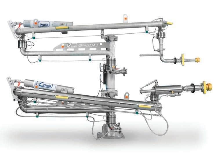
Added Values – Why use our CRYOLOAD?
• Easy to use by a single operator
• Long range of loading in rear and side configuration
• Self-compact balancing system
• Special insulated handles for cryogenic application
• Swivel joints with backup seals and leakage detection for high reliability
• Swivel joints with seals in Ultra High Molecular Weigh PE for high reliability
• Swivel joints with minimum rotation resistance for easy operation.
• Swivel joints with replaceable product seals and bearing module.
• Very easy maintenance
• Italian technology and quality for long life service
• Authorized services all over the world for installation and maintenance.
Please feel free to contact us at info@zipfluid.it
Compliant With:
• Machinery Dir. 2006/42/EC
• PED: Pressure Equipment Dir. 2014/68/EU.
• ATEX: Explosive Atmosphere Directive 2014/34/EU.
Design & Tested according to:
• ISO 16904
• EN1474.
• OCIMF
Main Technical specifications:
• Design temperature: -200° / +65°C
• Design pressure: 40 bar
• Test pressure: 60 bar
Swivel Joint with BackupSeals –
Material: Ultra High
Molecular Weigh PE
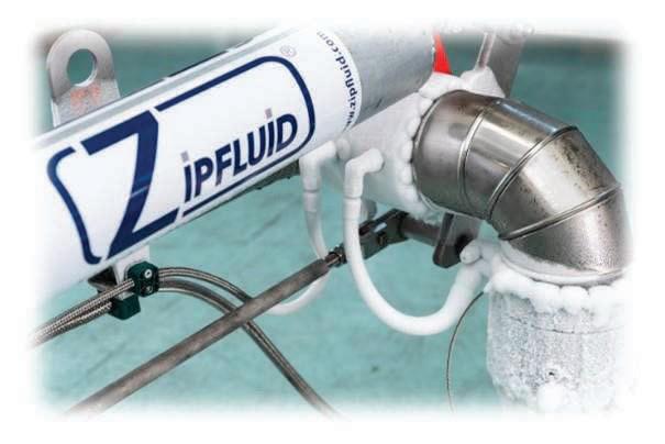


PLUS
HIGHER RELIABILITY
Made in Italy

Mark van Meel and Jürgen Essler, BRUGG Rohrsysteme GmbH, Germany, breaks down how the advent of stainless-pipes has altered small scale LNG for island populations.
In the ever-evolving landscape of the LNG industry, the pursuit of cost-effective and efficient solutions remains paramount. Island communities, amidst escalating demands for cleaner energy, are increasingly turning to LNG as a viable alternative to traditional oil-based sources, driven by the need to bring global energy-related carbon dioxide (CO2) emissions to net zero by 2050 and limiting the global temperature rise to 1.5˚C as underscored by the recent agreements made at COP28 in Dubai. Transitioning from oil to natural gas significantly reduces carbon emissions,
34
mitigating the environmental impact on island ecosystems. Embracing LNG as a cleaner and more sustainable energy source enables island communities to reduce their carbon footprint while enhancing energy security and resilience.
Transitioning to cleaner energy sources and achieving net-zero carbon emissions presents numerous challenges for island communities. One of the most important points is the high cost associated with adopting renewable energy technologies and infrastructure. Islands often rely heavily on imported fossil fuels, leading to inflated energy prices and

economic vulnerability. Furthermore, limited land availability may constrain the deployment of renewable energy systems, such as solar panels or wind turbines. Additionally, the intermittent nature of renewable energy sources poses challenges for maintaining a reliable power supply, especially in remote island locations. Grid stability and energy storage solutions become critical issues in ensuring a consistent energy supply. Moreover, transitioning away from traditional industries like fishing or tourism, which may have carbon footprints of their own, can create social and
35
economic tensions. Balancing environmental sustainability with economic development and social wellbeing is thus a delicate task for island communities striving for a cleaner, net-zero carbon future.
Versatility of flexible stainless-steel pipes
Crafted by industry leaders for decades, reeled flexible corrugated stainless-steel pipes offer a versatile departure
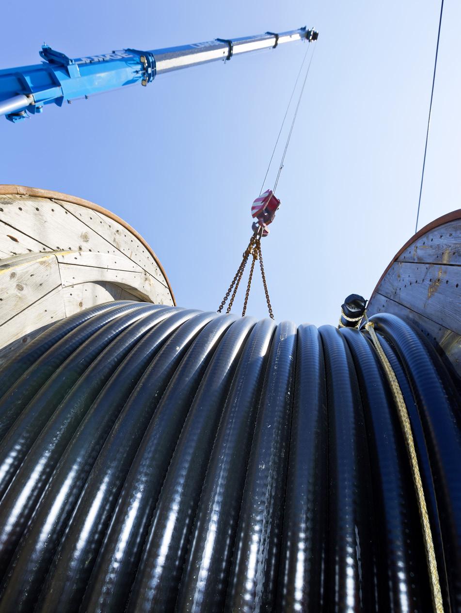
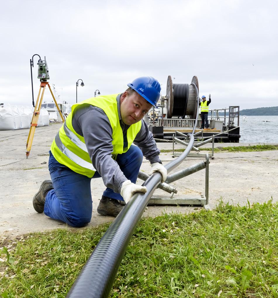
from conventional rigid pipelines. Available in sizes ranging from 0.5 – 12 in., these pipes cater to various LNG industry applications. These flexible pipes can be produced in long lengths of hundreds of meters on reels, factory tested, certified, and delivered ready for installation. Whether vacuum insulated or foam insulated, they boast effective insulation properties, ensuring safe and efficient LNG transport from source to destination.
While vacuum-insulated pipes excel in insulation performance, their foam-insulated counterparts provide a more cost-effective solution without compromising efficiency. Tailored for nearly static or dynamic installations, these flexible pipes are ideally suited for diverse LNG import projects, including those in near shore and coastal environments.
The evolution of LNG infrastructure: a case study
Consider the challenges faced by island communities or other remote areas without existing import infrastructure seeking to transition from oil to natural gas energy sources. Traditionally, establishing LNG import terminals posed significant financial and logistical hurdles. However, flexible stainless-steel pipes offer a transformative solution to this longstanding dilemma.
This case study delves into the implementation of small scale LNG import projects on islands, where weekly imports of up to 30 000 m³ of LNG are necessary to meet energy demands. Historically, the cost of traditional LNG import terminals has rendered many such projects economically unfeasible. Leveraging the innovative capabilities of flexible stainless-steel pipes, island communities can now transition to cleaner energy sources with speed, ease, and affordability.
Flexible corrugated stainless-steel cryogenic pipes offer a plethora of advantages for small scale LNG terminals, particularly beneficial for island nations. Their low heat inleak, facilitated by vacuum insulation, ensures optimal preservation of LNG, crucial for efficient storage and transportation. Moreover, their multi-directional flexibility and self-compensating nature allows integration into diverse terrains and operational setups. The plug-and-play feature, coupled with the ability to provide seemingly endless lengths, simplifies installation and scalability, catering to varying demands. Engineered with precision, these pipes offer bespoke solutions tailored to specific requirements, guaranteeing optimal performance. Additionally, their no-welding solution not only enhances safety but also expedites delivery and installation processes, making them a safer and faster alternative for LNG infrastructure development in remote island environments.
The installation of reeled flexible stainless-steel pipes in shallow water and near shore environments provides a cost-efficient alternative to conventional LNG infrastructure. Bypassing the need for extensive and expensive terminal facilities, these pipes enable the establishment of LNG import infrastructure at a fraction of the traditional cost and in a fraction of the time. Their flexibility accelerates deployment and installation, enhancing operational efficiency and expediting project timelines.
Furthermore, the conventional LNG infrastructure’s prohibitive costs have long hindered such projects. Enter flexible stainless-steel pipes – a revolutionary solution
36 April 2024
Figure 1. Reel of flexible stainless-steel pipe for transport to site.
Figure 2. Laying of flexible-stainless steel pipe.
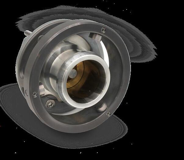


www.opwces.com Copyright © 2024 OPW Clean Energy Solutions CryoMac® 4 LNG Fueling Nozzle Maximum safety for LNG fuel technology For more information on Acme VJP scan the QR Code above Vacuum Jacketed Pipe (VJP) The most cost-effective way to transfer cryogenic liquids The New Website is Coming Soon! Explore both brands and o erings in one place Access to comprehensive Remarkable Product Search Expanded Markets & Applications The New Website is Coming Soon! Explore both brands and o erings in one place Access to comprehensive information Remarkable Product Search Expanded Markets & Applications Remarkable Product Search Explore both brands and offerings in one place Come visit OUR NEW WEBSITE! Expanded Markets & Applications Access to comprehensive information The New Website Coming Soon! Explore both brands and in one place Access to comprehensive information Remarkable Product Search Expanded Markets & Applications The New Website is Coming Soon! Explore both brands and o erings in one place Access to comprehensive information Remarkable Product Search Expanded Markets & Applications Patented nozzle safety feature is recognized in the market as a major failsafe advantage for the operator. Ball cage interface with receptacle adapter ring guides and locks the nozzle in place for optimum engagement and user interface to increase environmental seal life. DURABILITY þ SAFE “Safety Stop” for added safety and operator protection. For more information scan the QR Code above produce exceptional efficiencies across the entire system. series stainless steel. Insulation is a low vacuum with multiple layer insulation (MLI). The comprehensive component design to complete the system design, manufacture, and installation capability. Super-Insulation Cryogenic insulation for Nitrogen, Oxygen, Argon, Helium, Natural Gas, Carbon Dioxide, Hydrogen Stainless Steel Inner Pipe
promising unprecedented efficiency and cost-effectiveness for small scale LNG import endeavours.
Towards hydrogen and beyond
It is noteworthy that the adoption of flexible stainless-steel pipe systems not only revolutionises LNG imports, but also sets the stage for broader energy transitions. These pipes pave the way towards hydrogen as a fuel and hydrogen carriers like methanol and ammonia. Thus, they represent a pivotal step towards a more diverse and sustainable energy future.
Furthermore, the versatility of flexible stainless-steel pipes extends beyond hydrogen alone. They serve as essential conduits for a spectrum of alternative fuels and hydrogen carriers, including methanol and ammonia. By facilitating the transport of these substances, these pipes play a crucial role in expanding the scope of renewable energy solutions and reducing reliance on fossil fuels.
The potential of hydrogen as a fuel and hydrogen carriers like methanol and ammonia is undeniable. Hydrogen, when produced through renewable methods such as electrolysis, offers a clean and sustainable energy source with zero emissions. Methanol and ammonia, meanwhile, present viable alternatives for energy storage and distribution, enabling greater flexibility and scalability in renewable energy systems.
In essence, flexible stainless-steel pipes represent more than just conduits for fluid transportation; they embody the cornerstone of a cleaner, greener future. By accommodating the evolving needs of the hydrogen economy and facilitating the adoption of alternative fuels, these pipes are instrumental in shaping a sustainable energy landscape for generations to come.
For island communities embarking on the ambitious task of establishing LNG import infrastructure, the adoption of reeled plug-and-play flexible corrugated stainless-steel pipes


presents a bespoke solution, uniquely tailored to address the multifaceted challenges inherent to island environments. These pipes promise a plethora of advantages, encompassing safety, cost-effectiveness, schedule adherence, and quality control, all while intricately weaving in considerations for the delicate environmental and social fabric of island life.
Prefabricated construction techniques taking advantage of flexible plug-and-play LNG piping systems offer a multitude of advantages that revolutionise the traditional approach to building LNG import infrastructure projects. One significant benefit lies in the expedited construction timeline facilitated by prefabrication. By manufacturing the ready for use flexible piping systems off site in controlled environments, construction processes become more efficient and predictable, minimising the potential for delays due to adverse weather conditions or on-site mishaps. This efficiency translates into cost savings as well, as shorter construction periods reduce labour expenses and overhead costs associated with prolonged projects, ultimately bringing cleaner burning LNG faster to island communities. Moreover, prefabrication promotes sustainability by optimising material usage and minimising waste through precise manufacturing processes. Additionally, the controlled environment of prefabrication facilities ensures higher quality standards, as factors like temperature, humidity, and dust are regulated, leading to superior craftsmanship and durability of the final product. Thus, avoiding unnecessary delays at the terminal construction site. Beyond these practical advantages, prefabricated construction also offers versatility in design, allowing for customisation and adaptability to various import mooring terminal development phases and local project requirements. Furthermore, prefabrication promotes safety on construction sites by minimising on-site activities and potential hazards, thus creating a safer working environment for construction workers. Overall, the embrace of prefabricated construction techniques signifies a paradigm shift in the construction industry, promising enhanced efficiency, sustainability, safety, and quality in building LNG import projects at remote island locations.
Conclusion
The adoption of reeled flexible stainless-steel pipes represents a shift in the LNG industry, particularly for small scale import projects in island communities. By offering a cost-effective, efficient, and environmentally friendly alternative to traditional infrastructure, these pipes make previously unfeasible projects achievable. Moreover, their versatility extends beyond LNG, paving the way for broader energy transitions towards hydrogen and other alternative fuels. Reeled flexible corrugated stainless-steel pipes offer island communities a tailored solution for establishing LNG import infrastructure.
As island communities prioritise energy diversification, reliability and sustainability, the significance of flexible stainless-steel pipes cannot be overstated. Through collaboration and innovation, the LNG industry is poised to usher in a new era of sustainable development. By embracing proven pre-fab plug-and-play construction techniques and flexible stainless-steel pipes, island nations can embark on a transformative journey towards a cleaner, more resilient energy future. Working together can drive positive change for both the industry and the planet, shaping a brighter tomorrow for generations to come.
38 April 2024
Figure 3. Vacuum insulated flexible pipe.
Figure 4. Foam insulated flexible pipe.
High-pressure LNG fuel systems are an increasingly popular solution in shipping, and new innovative solutions are now being developed to meet the demand for leak-free fuel supply systems components with long service life. Rasmus Gregersen, Svanehøj, Denmark, provides a technical overview of one of these new solutions.
The uptake of LNG as a marine fuel has been very strong in recent years, especially among newbuildings. According to the DNV database for alternative fuels, LNG-powered ships passed the 1000 ships milestone in 2023 (of which 469 were in operation). Almost 60% of
these vessels have been ordered in 2021 – 2023.
Most of the new LNG-powered vessels will be built with two-stroke cycle engines. In fact, more than 80% of all LNG ships ordered in 2023 had two-stroke engines, according to data from Clarksons. A primary reason is that two-stroke

engines significantly reduce methane slips and are generally considered more fuel-efficient than four-stroke engines, which makes them a preferred option for many shipping companies, especially for larger vessels.
Because of its operating principles, a two-stroke engine
39
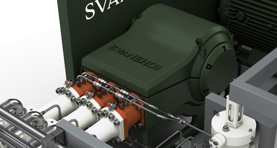
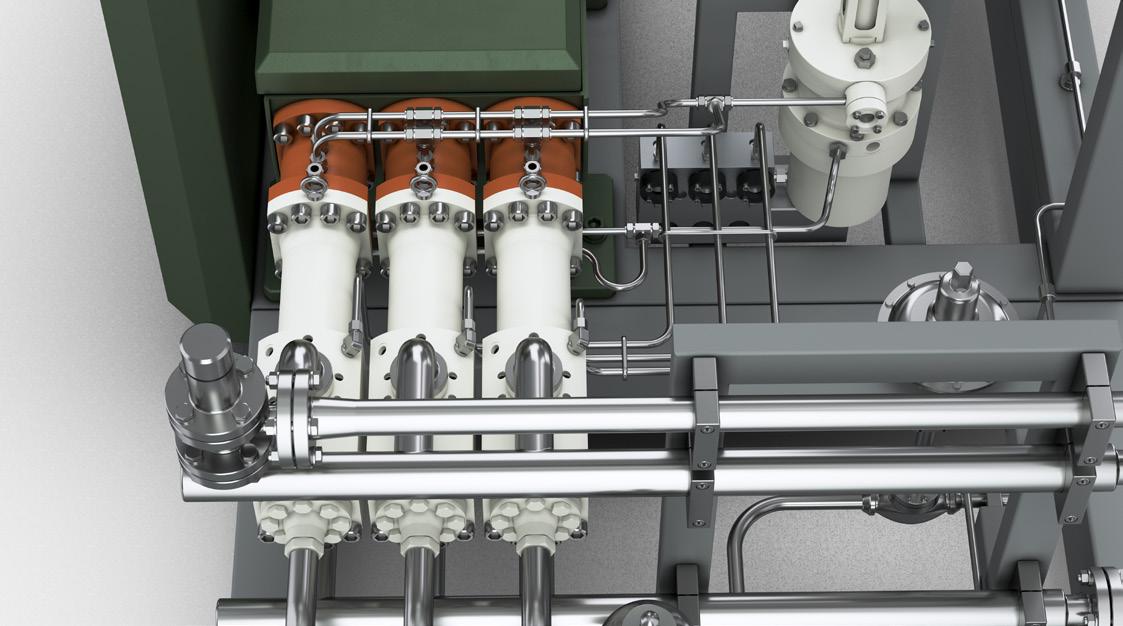
Svanehøj HPP Triplex Unit – technical infomation
A triplex type high pressure piston pump for LNG, with belt drive system, installed on a skid for easy transportation and installation.
z
z
z
z
z
z
z
z
z
• Three pieces of cold ends.
• ATEX 45 kW motor downrated for VFD operation.
• Media: LNG.
• Capacity: 11.5 – 72 l/min. (0.7-4.3 m 3 /h).
• Inlet pressure: 5 – 14 bar.
• Design pressure: 350 bar.
• Working pressure: 315 bar.
• Minimum operation temperature: -163˚C .
• Unit dimensions: 2600 x 1390 x 1200 mm.
needs a higher fuel injection pressure (300 bar). Therefore, the fuel gas supply system (FGSS) design for a two-stroke engine is more complex than for a four-stroke engine, as it represents the integration of mechanical, thermal, and electronic components designed to handle LNG safely and efficiently. Thus, the system requires components that can handle the increased pressure, contributing to better fuel atomization and combustion, all within the constraints of a compact and continuous operating cycle.
The cold end: Ensuring an efficient transfer of LNG to the engine
The objective of the FGSS is to deliver fuel to the engine at the required temperature and pressure. In the case of LNG, the fuel is pumped in its liquid form (at -162˚C/-260˚F) from the storage tank and vaporised to a gaseous state before being injected into the engine.
In a high-pressure FGSS for LNG, the cold end is critical in maintaining the natural gas in a liquid state during pumping, ensuring it does not vaporise prematurely. This is essential for maintaining an efficient and safe transfer to the engine under high pressure. Cold ends directly impact the fuel system’s overall performance, influencing fuel delivery rates, energy efficiency, and emission levels.
As the cold end is the component that comes into direct contact with the cryogenic fluid, the design, construction, and material selection are crucial for the successful operation. High-pressure LNG pumps are typically built with three cold ends, which is considered the optimum design regarding flow, efficiency, and reliability in operation.
A new pump-designhigh-pressure for longer service intervals
High-pressure LNG fuel systems are still relatively new to the maritime industry, and a common issue is the wear and tear on critical components. This is driving efforts to improve LNG pump technology to enhance reliability and operational efficiency.
Svanehøj has addressed the need for more durable and maintenance-friendly components by developing a complete high-pressure pump solution exclusively designed for marine LNG fuel systems, and a separate cold-end component for LNG retrofit projects.
The ‘Svanehøj HPP Triplex Unit’ is a reciprocating (piston) pump capable of achieving and maintaining very high pressures under cryogenic conditions. The pump delivers a pressure of 315 bar and a flow rate of 4.3 m 3 /h.
The compact unit is designed with a belt drive system, installed on a skid for easy transportation and installation.
40 April 2024
Figure 1. The HPP Triplex Unit is a compact solution with a belt drive system and three combined cold ends designed for optimal flow and longer service intervals.
Figure 2. The new cold end design includes a patented low-pressure sealing arrangement that reduces friction, ensuring longer service intervals. To ensure high efficiency and low-pressure drop, the design also includes a patented inlet valve design.
DISCOVER ENHANCED SERVICE INTERVALS AND SMART MAINTENANCE SOLUTIONS

UNLOCKING EFFICIENCY WITH THE HPP TRIPLEX PUMP UNIT
The HPP Triplex Pump Unit is designed to meet the demand for an efficient and high-performing LNG fuel supply system. With the addition of the new pump unit Svanehøj is the onestop supplier for both low- and high-pressure LNG fuel pump solutions throughout the green transition.
FEATURES:
• Three cold ends with longer service intervals
• Innovative lubricated low-pressure sealing arrangement
• Smart seal cartridge solution for swift maintenance
• New inlet valve design for lower pressure drop and higher efficiency
svanehoj.com
Powering a better future
With the HPP Triplex Unit, Svanehøj has introduced two patented innovations for the design of the cold end:
z A new low-pressure sealing system that reduces friction, ensuring longer service intervals.
z A new inlet valve design, ensuring higher efficiency and low-pressure drop.
As a part of the HPP Triplex Unit, the company has also developed a drive unit with forced lubrication specifically designed for the capacity and requirements of the pump. Furthermore, it has optimised the design and material composition of the cylinder and added a copper-based alloy, thereby reducing the cooling down time of the pump by approximately 50%.
An active sealing system
High-pressure reciprocating pumps for LNG typically use non-lubricated sealing systems. While this design benefits operating in cryogenic environments, it also causes higher friction and, therefore, more rapid degradation. Svanehøj has solved this issue by introducing a new, patented active sealing system with an incorporated oil chamber. This approach serves a dual purpose, as the oil film lubricates the seals and functions as a gas barrier due to a higher differential pressure (2 – 5 bar), ensuring a minimum of gas leakage. Although the design is new, the concept is well-proven, as the company has used it for shaft sealing on its low-pressure centrifugal pumps for decades.
The active sealing system is positioned close to the cryogenic gas flow. The company has separated the pump’s hot and cold ends with a cofferdam to prevent the oil from freezing, thereby reducing cold migration. Additionally, heat tracing has been installed between the flanges to consistently maintain the oil chamber’s temperature above the freezing point.
Replacing seals in a high-pressure gas pump is a critical maintenance task requiring careful planning and precision. Therefore, as part of the active sealing system, Svanehøj has introduced a seal cartridge solution with pre-installed seals, contributing to an effective pump overhaul. Instead of replacing each seal one by one or the entire sealing housing, the new design only requires a replacement of the cartridge itself.
A new patented inlet valve design
LNG’s low boiling point at atmospheric pressure makes cavitation a common issue for high-pressure LNG pumps. Cavitation occurs when the local pressure in the liquid falls below the vapour pressure, causing bubbles or cavities to form. This can significantly impact the pump’s performance and longevity and cause significant mechanical damage to pump components.
In the design of the HPP Triplex Unit, the company has focused on increasing inlet flow and minimising pressure losses. By expanding the intake area of the inlet valve and filling the compression chamber more efficiently, Svanehøj has reduced the inlet pressure by at least 2 bar, significantly reducing the risk of cavitation. It also allows more efficient use of the fuel tank because the lower inlet
pressure reduces energy consumption and boil-off gas, thereby increasing the usable volume of LNG from the tank.
The drive unit
The drive unit serves as the power source that drives the pump to deliver LNG to the ship’s engines. The drive unit is developed explicitly for the HPP Triplex Unit and designed with a fibre-reinforced belt drive connected to two pulleys with a 3.82 gearing ratio. A connecting rod transmits the rotation of the crankshaft to the reciprocating motion of the piston and piston rod. The main bearings are of the spherical roller type to accommodate the deflection of the crankshaft. The connecting rod bearing has a double-row full complement cylindrical roller bearing. It incorporates a maximum number of rollers to make it suitable for heavy radial loads in combination with moderate speeds.
The cylinder
The pump cylinder handles and pressurises the LNG as it moves through the pump system. Keeping LNG in its liquid form requires cryogenic conditions. As a result, the components must be highly reliable, durable, and constructed from materials that function optimally under cryogenic conditions. The cylinder is made from materials carefully selected for their behaviour, strength, and durability in harsh environments at low temperatures.
Due to LNG’s cryogenic nature, the cylinder’s temperature is critical to prevent thermal shock and vaporisation. Cooling down ensures that the materials have reached a stable state that matches the operational conditions of LNG handling.
In the design of the HPP Triplex Unit, Svanehøj has modified the material composition and added a copper-based alloy, which has reduced the cool-down time by approximately 50%.
Conclusion
Since 2010, the LNG-powered fleet has grown consistently by 20 – 40%/y. DNV predicts that more than 1000 LNG-powered ships will be in operation by the end of 2027, which is more than a doubling of today’s fleet. As high-pressure LNG fuel systems offer lower fuel consumption and reduced methane slips, there will be strong demand for more durable critical components and solutions in the coming years.
As part of its ESG strategy, Svanehøj has committed to directing at least 95% of its R&D investments at solutions and products that support the energy transition, including pumps and equipment for the LNG segment. Drawing from extensive expertise in cryogenic solutions, the company has already invested significantly in new LNG products and services, including the HPP Triplex Unit and a new full-range series of electric low-pressure submerged fuel pumps, the CS Fuel Pump.
Based on the belief that transition fuels are essential to achieving net zero and that natural gas is by far the best option, Svanehøj is committed to continuously innovating its product portfolio designs and service models at the lowest possible environmental lifecycle cost.
42 April 2024
Clayton Kale, Director of Marketing, AMECO, USA, maps out an integrated site services approach for constructing LNG facilities.
A focus on the behind-the-scenes

The world is thirsty for a cleaner source of energy to replace coal. Energy producers in Asia have driven up the global demand for natural gas, and Europe’s move away from its Russian supply has developed new markets for energy export from North America. This rising demand for natural gas has triggered the start of numerous LNG projects across North America. Dozens of LNG projects are in the planning stages or actively developing in the US, primarily along the Gulf Coast (if they are not derailed by administrative red tape). Although many of these projects plan to supply natural gas to Europe, a huge demand persists in Asia. This dual East-West demand puts Canada, specifically Western Canada, in a prime position to be a world leader in LNG exports to Asian markets.
LNG Canada is the first of what could be many liquefaction plants built in British Columbia. Executing a project of this magnitude anywhere comes with great challenges. But executing a megaproject in the remote parts of Western Canada brings with
it additional challenges. How do project managers supply a workforce large enough to support the project? How can construction managers ensure that the right tools and equipment are in place when they are needed, considering supply chain challenges and remote jobsites? And finally – but certainly not the least considered – is how can these projects, which are being built within the traditional, unceded territories of various First Nations, both respect the land they are being built on while also creating economic opportunities for the indigenous people who live and work there?
All of these challenges can be mitigated with forethought, partnerships made in good faith, and a lot of planning.
An integrated approach to construction
Planning is essential for constructing a project as large as an LNG liquefaction and export facility. That is obvious on its face.
43
With a total installed cost landing in the tens of billions of dollars (both in Canadian or US dollars) complex process equipment, intricate piping design, sensitive instrumentation, and rigorous
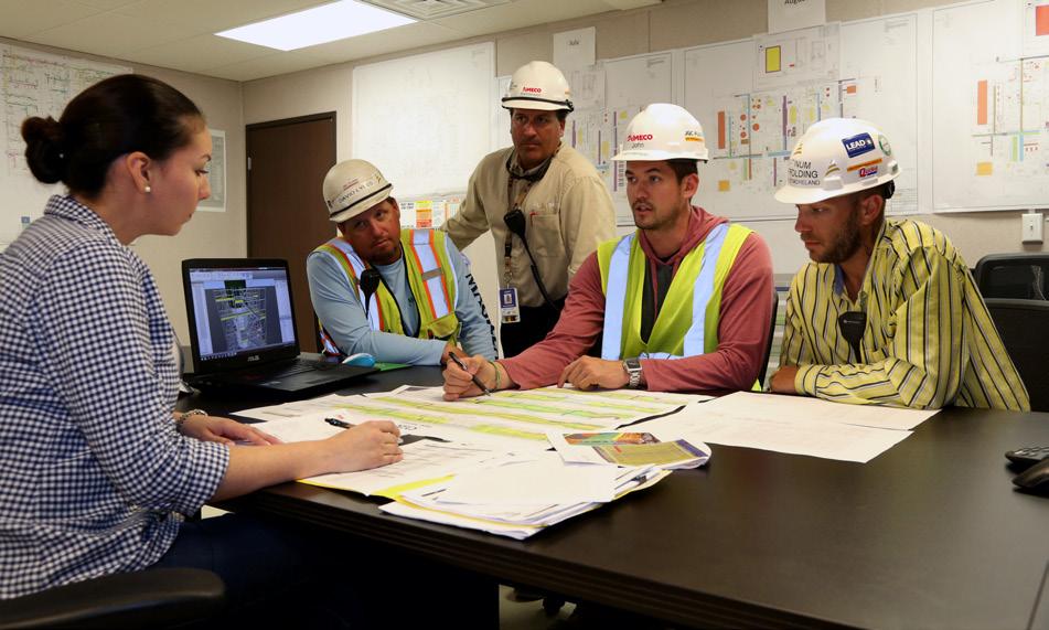
Engaging Indigenous partners
Building a project the size and scope of an LNG export facility in Western Canada means that the site is going to have a major impact on the Indigenous Peoples who live in the territory. To ensure that impact is a net positive, it is critical to understand the importance of community engagement and to foster meaningful partnerships with the Indigenous People native to the region. These partnerships will benefit the project, but even more, these are opportunities for economic growth and job training for the Indigenous communities in Western Canada.
A key pathway to building engagement is to offer a broad range of inclusive employment opportunities. AMECO, for example, posts a wide spectrum of job openings – from those that require a high level of training and certification, like finance positions, heavy mechanics, scaffolding tradespeople, and equipment operators to jobs that require very little experience but are great career starting points such as labourers and entry level warehouse positions. By providing entry level jobs, alongside other available positions, AMECO provides on-the-job training that can be used to build a long and successful career.
It is a benefit that long-term construction projects, such as an LNG site, transition into operating facilities, as they can lead to long-term employment that does not require local workers to move from their community. This can help build a legacy and future labour capacity within the local Indigenous community.
Finally, to better engage the Indigenous Peoples, committing to a process of continuous improvement in engagement strategies is critical. Set high standards for engagement, and maintain positive and productive relationships with Indigenous communities and leaders.
With intention, construction contractors, service contractors, and other industrial firms can foster respectful, meaningful, and mutually beneficial partnerships that ensure sustainable development and community empowerment.
timelines, there is no way an LNG project would be successful without hours of painstaking planning and collaboration.
To improve results in almost every aspect of construction, such as safety, budget, and schedule, planners should invest as much care and detailed planning in providing construction indirect services as they do in direct construction activities. This article outlines three examples of indirect construction services that will make the biggest impact on safety, schedule, and total installed cost when integrated into planning alongside detailed engineering.
Integrated scaffold solution
Scaffolding exemplifies how an integrated approach can significantly impact key factors like safety, budget, and schedule. Scaffold safety is a key concern in British Columbia (seven of the nine Canadian projects that AMECO is tracking are in British Columbia) where wrapped scaffold structures must be engineered and stamped. To make this cost effective, the scaffold engineer needs to be engaged from the planning stages. This early involvement offers another advantage: it eliminates costly rework. When scaffold designers are involved early, they spot potential conflicts and either eliminate them or prepare ahead of time for modifications that will be needed. This has a dramatic impact on both labour hours and overall cost.
For example, a recent AMECO scaffold analysis comparing an integrated approach vs a conventional approach on a major LNG project found that while planning hours were higher in the integrated approach, modifications were eliminated. This resulted in a decrease of more than 2000 hours; this led to almost CAN$215 000 in modification cost savings. Total design hours were also reduced by 35%. In total, the integrated approach led to overall savings of 60% compared to the traditional approach.
It is challenging to find enough labour in the construction industry today. This labour challenge is exacerbated in remote areas, including where LNG Canada and Woodfibre LNG are being built. That makes efficient scaffold labour a critical component of project execution, and projects should ensure that the scaffold provider understands the labour needs for the type of scaffolding material that is being used. For example, ringlock scaffolding material typically requires crews of 4 – 6 labourers, while other scaffold systems, such as PERI Up, can be erected by teams of two or three. Meanwhile, different scaffolding systems have different requirements for tools (which can increase drop hazards), decking (which can contribute to trip hazards), and consumables, such as tie wire and lumber (which is time consuming to install, increases cleanup and disposal costs, and counters site environmental and sustainability efforts). Understanding these scaffolding requirements allows project directors to see the big picture when developing site access plans.
A sitewide tool solution
On a large complex project, there will be a need for a lot of tools and a steady supply of consumables. Tool costs can quickly escalate without foresight. Subcontractors often say they prefer to provide their own tools. What is not often said is that tool provision often is where they build in margin. But besides that, allowing various contractors to bring in various brands of tools opens the risk of variations in tool calibration and tool cribs stocked with redundant, but incompatible consumables.
Working with an integrated partner to provide tools sitewide can dramatically affect overall tool cost over the project’s lifecycle. Through careful analysis of work packages, a robust planner can understand what tools and consumables are needed when based
44 April 2024
Figure 1. Bringing indirect services in during the planning stages can have a dramatic effect on the cost of tool and consumables, scaffolding material and labour, and equipment provision and management.
on the craft curve. Since they are procuring tools for an entire site of thousands of labourers, they can obtain both favourable terms on tool rates while also getting white glove treatment from the tool providers who are eager to ensure orders are delivered without interruption.
Consequently, as the integrated partner has a bird’s eye view of all tool usage, tool upkeep can be planned over the life of the project and tool loss can be monitored and kept in check starting from day one.
Beyond equipment rentals
Simple equipment rental becomes unfeasible for a project as large as an LNG plant build. Managing it would be a nightmare. Keeping track of what is on rent and off rent, what needs preventative maintenance, which piece has broken down and where, which pieces were delayed in transit and for how long – all of that is a full time, thankless, and stressful job. If equipment provision is to be left up to the subcontractors, there are multiple people scrambling around the same pool of equipment, each is less likely to be taking preventative maintenance impacts to equipment safety and readiness into account, equipment redundancies lead to over-payment and costly under-utilisation, and again, leaving it up to subs provides a place for margin to be built into their contracts. Instead, an approach where an integrated partner handles all aspects of equipment and vehicle provision, co-ordination, maintenance, analysis, and reporting simplifies the entire process for everyone onsite. Fuelling is managed centrally. Maintenance is managed in a centralised equipment yard, and the site is not tied exclusively to one equipment supplier, which can drive down both cost and wait times for in-demand equipment.
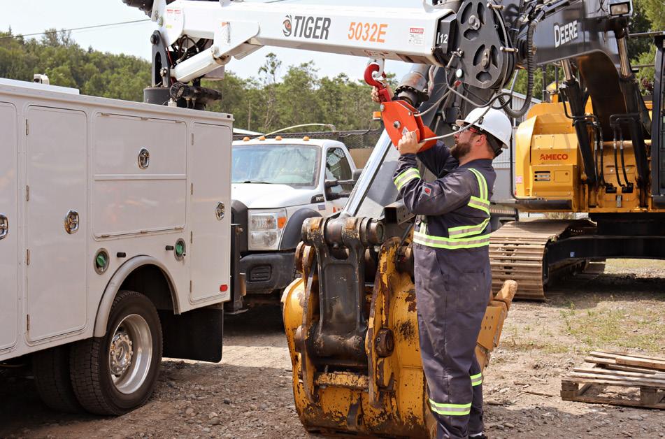
The theme is becoming evident now. Much like a sitewide, pre-planned approach to scaffolding and tools, an integrated approach to vehicles and construction equipment can have drastic effects on project efficiency and overall cost.
Putting it all together
The direct action of construction, perhaps rightly, gets most of the attention when it comes to grading a project’s results. After all, the metric of “did the project get completed” is a pretty clear one. However, like a Hollywood blockbuster rolling line after line of credits, there is a lot of unseen work that goes into success. Taking the time and effort to get the indirects right can have an outsized impact on the overall project.

What’s today’s emergency?
Figure 2. Centralising equipment fleet provision and maintenance can have a deep impact on equipment uptime, availability, and cost.

46
Rubén David Monje, Technology Services Consultant, KBC – A Yokogawa Company, discusses how integrated operations can optimise scheduling, production accounting and energy cost, and manage emissions on LNG sites.
At the core of every successful LNG site, whether it is engaged in liquefaction or regasification operations, lies a trio of indispensable activities: optimal scheduling, production accounting, and expert management of energy costs and greenhouse gas (GHG) emissions.
Effective operations must be scheduled to ensure feasible and cost-efficient operations, including the ability to simulate scenarios for viable assessment under possible operational disruptions such as LNG tanker delays.
Production accounting is a mature technology that helps close the daily production mass balance and address data reconciliation issues.1 Managing energy costs and GHG emissions requires a strategic approach that involves the calculation of emissions and energy metrics, optimisation, and real-time reporting within a given timeframe, as per the site’s local regulations.2,3,4
All these activities can only be effectively performed under a digital environment. The advanced technology solutions use mathematical tools for optimisation, integrate first principle-based models, and enable data gathering from different sources while evaluating simulated scenarios and case studies. Additionally, the software offers the capability to

calculate and report custom key performance indicators (KPIs) and present results to end users via a user-friendly interface.
This article provides references and examples that highlight how these advanced technologies produce tangible benefits to LNG operators.
Production accounting and data reconciliation
The LNG industry holds significant value potential via its existing real-time data availability. However, it suffers significant financial losses attributed to the challenge of managing, tracking, integrating, and sustaining material and energy balances data in a synchronised manner across the entire business. The inherent complexity of processes, poorly integrated workflows, misinformation, and the associated costs for maintenance all contribute to diminishing the perceived value of production accounting systems (PAS). Some companies even marginalise this activity to ‘only an administrative task.’
By adopting accounting best practices and incorporating engineering knowledge beyond the yield accounting methodologies, companies can extract maximum value from the reconciled mass balance data. This strategic shift expedites
47
tasks while enhancing the relevance and accuracy of the information generated.
A PAS was implemented in a European LNG facility. The main objective was to capture all necessary information for calculating inventories and material movements within a specific timeframe. The PAS excelled in data reconciliation, specifically detecting losses, custody transfer discrepancies, and data input errors.
The solution provided the following characteristics:
z Modelling of 11 pipelines for feed gas input.
z Integration with accounting and production scheduling.
z Integration with commercial gas system.
z Integration with upstream systems (well operation).
z Integration with plant historian for flow meters and composition data reading.
Production accounting models, inventories, material movements, and other business operations within the hydrocarbon industry were used to generate a mathematical data reconciliation model, as illustrated in Figure 1.
The entire LNG site and individual process units relied on the PAS, which played a pivotal role of calculating a comprehensive end-to-end mass balance that encompassed both bulk and individual component assessments. This functionality enabled the LNG facilities to closely track inventories and properties of the stored and exchanged materials, including energy received and/or dispatched, mix density, molecular weight, Wobbe index, and more.
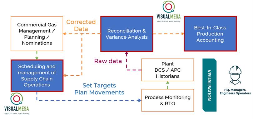
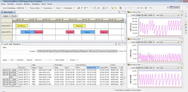
Once the mass balance is solved, and all the mixture compositions are calculated, the PAS becomes an indispensable tool to create KPIs. These KPIs serve as valuable metrics to help operations and management monitor and optimise their LNG workflows. For example, calculating and reporting KPIs included monitoring the amount of boil-off gas resulting from loading and unloading operations, comparing planned with actual monthly operations, tracking composition variations, and evaluating evaporative losses.
In this case study, the operator was able to generate KPIs from the reconciled mass balance and composition data. Additionally, the gross error detection engine identified potentially faulty meters that needed to be recalibrated.
To enhance operations, operators used the PAS results. More than 45 different reports were generated for the European LNG site, covering operations, inventories, tank movements, process unit reports, fuel consumption reports, balance reports, site losses, unit loss balance issues, balance audit reports, and more. By the end of the project, the PAS had integrated seamlessly with all business processes throughout the LNG supply chain, ensuring operational efficiency and data-driven decision-making.
Scheduling and operations optimisation
For the European LNG processing facility, a scheduling system was developed via the simulation of an integrated model. With this powerful decision-support system, the LNG facility was able to gain visibility into both its logistic and process unit operations via a hybrid continuous and discrete event simulation approach. Flow rates, inventories, and material properties were continuously changing control variables in the continuous simulator, which enabled the integration of differential equations. Meanwhile, the discrete event simulator reproduced the behaviour of discrete operations such as alignments, tank movements, receptions, and shipments, as shown in Figure 2.
Furthermore, this scheduling system allowed multiple users and/or schedulers the ability to access the same scheduling scenario simultaneously to facilitate collaboration and enhance decision-making. The business processes inherent in the LNG value chain were also accommodated on a short, medium, and long-term scheduling basis. In turn, this flexibility enabled the conversion of annual delivery programmes into a feasible day-to-day operating schedule for the entire supply chain – from gas wells, gas plants, and liquefaction plants to vessels and LNG regasification terminals – balancing supply and demand while aligning commercial needs with operational capability.
Finally, this LNG processing facility was able to monitor the progress of current operations and environment status to capture potentially disruptive events such as the late arrival of an LNG tanker, highlighting potential future risks by simulating consequences of possible disturbances in the supply chain. With the model, a schedule of vessel arrivals, jetty allocations, and loading operations was developed and maintained, and terminal facilities were managed to coordinate lifting of products with the production plan.
The material properties of LNG tanks inventory could be inspected in a dedicated report to analyse the prediction of quality properties and compositions for final products and to assess the impact of incoming gas compositions and production capacity decisions on final product specifications.
48 April 2024
Figure 1. PAS as part of the intergrated production model for LNG supply chain management.
Figure 2. Supply chain and scheduling system, Gantt charts and inventory projections visualisation.
The solutions were displayed in a graphical user interface (GUI) where the user could study and modify them. From the same interface, operations reports were generated in PDF, HTML, or XLS format, ensuring an easy sharing process.
Upon completing the implementation project, the scheduling system allowed for constant verification of the schedule, checking the feasibility of the operations, and assessing the schedule quality based on performance indicators. This was possible through the use of updated projections of inventories and material properties that could be automatically updated when the operations plan or plant data were modified.
Tracking and reporting metrics
In the case of the energy management system (EMS),6,7 it was applied at an Asian LNG regasification plant to calculate emissions and energy metrics that needed to be reported to the local authorities. Due to this capability of paramount importance, the site was able to qualify for ISO 50001 certification.
An online model of the process energy and emissions was developed to provide a graphic representation of how the different systems (process, utilities) interact for the regasification process. It was possible to calculate and historise energy and GHG emissions related metrics in real time by using a validated plant model fed with live data.
Data integration was crucial for the calculations to succeed. Thus, the EMS included specific libraries to communicate natively with the most commonly used historians in the industry and connect with real-time data bases through OLE for Process Control (OPC) or other protocols. At this Asian facility, the module for communicating with relational databases was also useful for retrieving data using SQL queries.
A variety of KPIs were calculated and historised, including but not limited to specific energy consumptions for different envelopes in the process (booster pumps, regasification, overall), pump efficiency, deviations in pumping power from designs, lost opportunity costs linked to deviations from operating parameters, heat exchanger overall heat transfer coefficient for fouling monitoring and GHG emissions as demonstrated in Figure 3.
When a given KPI surpassed a limit value, the system generated an alarm. Besides being displayed in the web GUI, as illustrated in Figure 4, these alarms also could fire email messages to notify plant staff about deviations from operational ranges. As a result of the integrated drill-down feature of the GUI, users could pinpoint and contextualise the deviations, enabling them to identify the root cause of the alarm. This was especially useful not only to improve operations within targets but also to detect a list of possible malfunctioning metering devices that could explain the deviation in the KPIs expected values.
The web interface provided access to calculation results, allowing for monitoring, analysis, and optimisation of the digital twin.
After project commissioning, this EMS implementation allowed the customer to automatically prepare reports that were sent to local authorities containing the calculated KPIs.
Conclusion
This paper discussed how LNG operations can improve their site’s efficiency, reduce costs, and comply with environmental regulations by integrating a scheduling and production
accounting system with an EMS. These advanced technology solutions offer the firm an advantage by streamlining complex processes, optimising resource utilisation, and providing real-time insights for decision-making.
First, a European LNG facility proved that a PAS was more than just an administrative task. By implementing best practices and seamlessly integrating the application with various systems, production accounting ensured accurate data reconciliation and generated valuable KPIs. Now, operators can monitor and optimise LNG operations by identifying potential issues such as faulty meters based on these KPIs, derived from mass balance and composition information.
Additionally, the case study discussed how the European LNG processing facility used scheduling systems to offer powerful decision-support tools. By using a hybrid simulation approach, these applications provide visibility into both logistics and process unit operations. This enables efficient scheduling across the whole supply chain, aligning commercial needs with operational capacity, and mitigating risks by simulating potential disruptions.
Second, the Asian LNG regasification plant’s EMS goes beyond tracking emissions. By integrating real-time data into a plant model, the EMS calculates and historises energy and GHG emissions metrics. This not only helped the plant achieve ISO 50001 certification but also allowed for continuous monitoring, analysis, and optimisation of energy consumption.
In essence, the convergence of these advanced technology solutions in LNG operations creates a comprehensive framework for sustainability, operational excellence, and regulatory compliance. The tangible benefits witnessed in various projects underline the transformative potential of adopting these digital applications in the LNG industry.
References
Available on request.
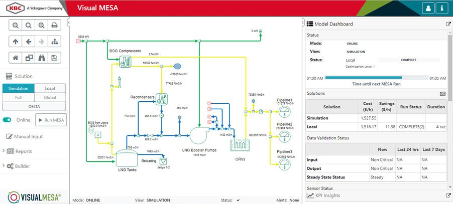
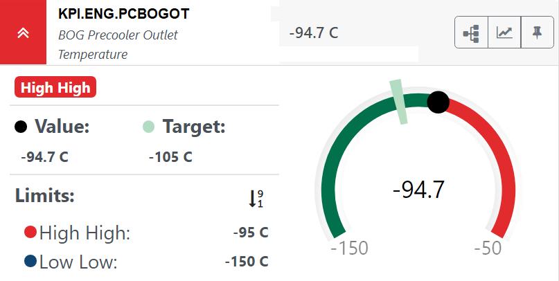
April 2024 49
Figure 3. EMS web graphical user interface (GUI) for an LNG regasification process.
Figure 4. EMS KPIs are made abailable in a web GUI.
LNG terminals, both for import (re-gasification) and export (liquefaction), require area for large storage tanks and sophisticated process plants. While onshore sites may offer the space, building onshore LNG plants on remote land is a complex and challenging task. Large construction projects in the field expose developers to complex logistics and significant risk.
Seatrium Ltd, headquartered in Singapore, has achieved the world’s first FLNG conversions (Figure 1), and is the only organisation in the world to deliver two floating LNG (FLNG) conversions: GOLAR Hilli in 2017 and Gimi in 2023. In addition, Seatrium has delivered several FSRUs.
Floating solutions offer a cost-effective remedy to the issue of on-location construction and site-preparation for small scale LNG terminal developments greater than 20 000 m3 and less than 90 000 m3. By integrating the storage in a vessel hull and process plant on deck, the majority of the terminal – except necessary mooring and jetty civil works – can be pre-fabricated

at a shipyard. The floating solutions offers developers the opportunity to construct complex LNG facilities efficiently in a controlled shipyard environment with established labour, equipment, steel fabrication facility, procurement, and logistics support. The floating solutions are highly flexible and can be customised to a developer’s requirement easily.
Another alternative
Another good alternative marine solution for small scale LNG is the GraviFloat, which may be used in the design and development of LNG import or export terminals that are modular, scalable, and re-deployable with fixed at-shore, near-shore, or offshore placement.
The platform is a fixed, near-shore storage solution fulfilling all requirements for LNG terminals to serve as a platform for LNG import and export terminal applications. This solution includes an integrated jetty solution for LNG carriers to perform offloading or loading operation. GraviFloat allows the
Seatrium Ltd considers an alternative marine solution for small scale LNG.
50
entire terminal to be constructed in a controlled environment at a shipyard, before being transported and installed effectively on site. For GraviFloat, the structures and equipment do not have to be designed to withstand motions and accelerations as compared to other floater solutions.
How it works
The Gravifloat Module is built in two parts: the main module named GraviFloat, and the associated seabed foundation module named GraviDock.
The GraviFloat and GraviDock, constituting a LNG terminal, are both developed such that they may be built at a shipyard using conventional shipbuilding techniques. The GraviFloat and GraviDock will then be floated from the yard to the site on top of heavy lift vessels. The GraviDock is to be pre-installed on the seabed and acts as a foundation for the GraviFloat and quay for LNG carriers. This facility solution will normally require limited or no seabed preparation prior to
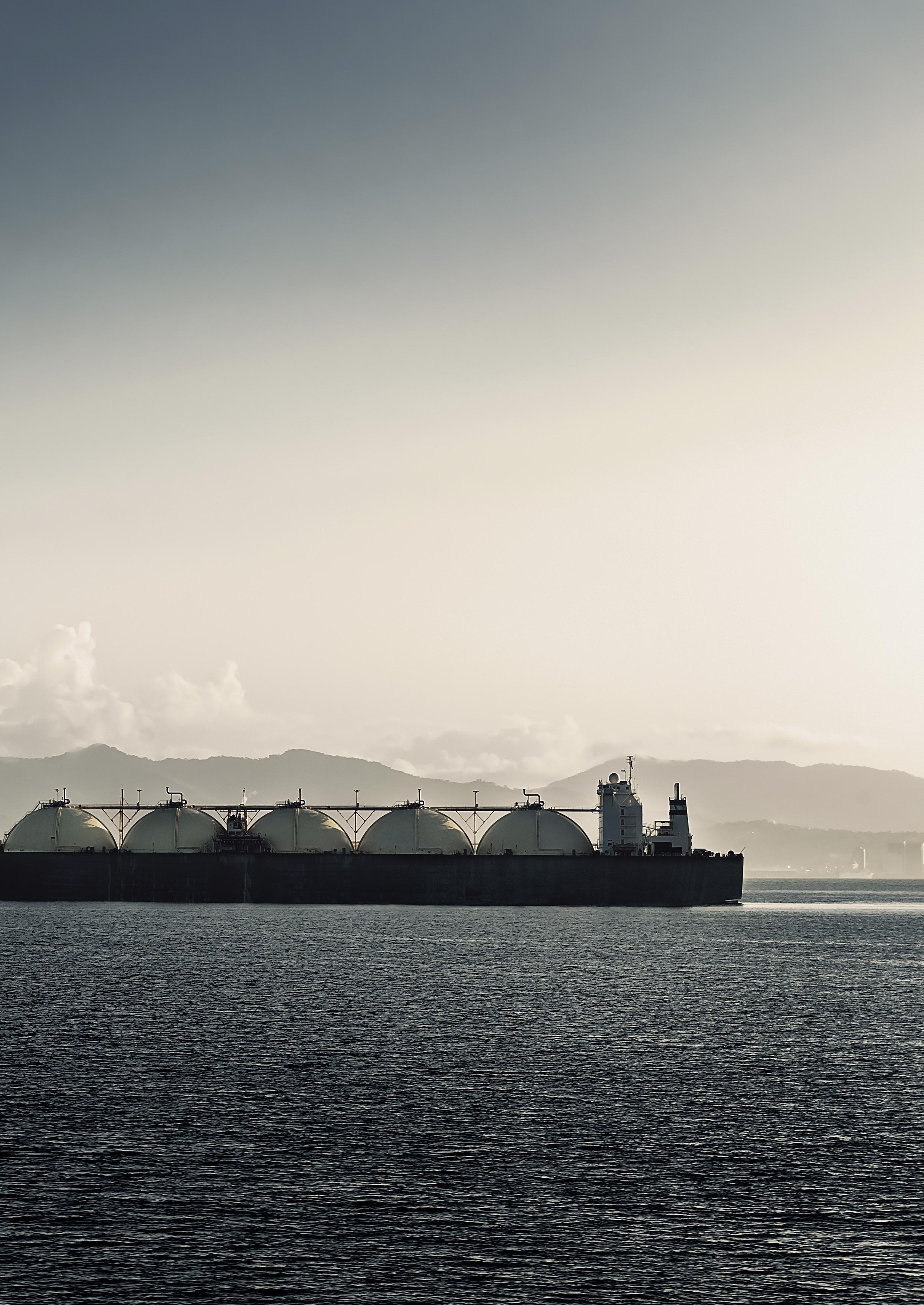
its installation. The effective installation and provision of built-in quay will reduce the total project realisation time. The GraviDock can be completed early at the yard time and then installed on the site seabed prior to GraviFloat arrival. The GraviDock is then ready for a quick and effective arrival and installation of the GraviFloat, which will arrive with pre-commissioned topside facilities.
Proper site assessment studies including meta-ocean, geotechnical assessment, and soil sensitivity shall be performed to establish the foundation design with respect to the vertical pile capacity. The foundation design will comply to classification societies’ guidelines using the relevant API standards as the basis for design. Where no specific guidelines are given, the assessment will be based on recommended practices from selected classification societies and other design standards such as ISO standards and Eurocode standards in addition to industry practice. The GraviFloat is typically installed with a design vertical load (by used of ballast)
51
during installation to reduce pile forces throughout facility lifetime. The pile concept is not sensitive for weight changes during the design and construction.
The installation of the GraviFloat into the pre-installed GraviDock is a quick float over, de-ballast, and lock operation. The GraviFloat provides an additional extra outer shell protection by way of its GraviDock for LNG carriers which are berthing alongside its jetty.
The integrated facility is designed, and will be built and fixed, to comply with all national and international rules, as well as contractual requirements and specifications so it is fit for operation at the specific site. The design life of a GraviFloat
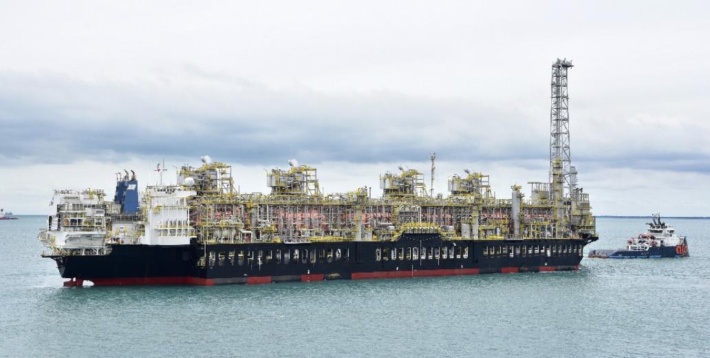
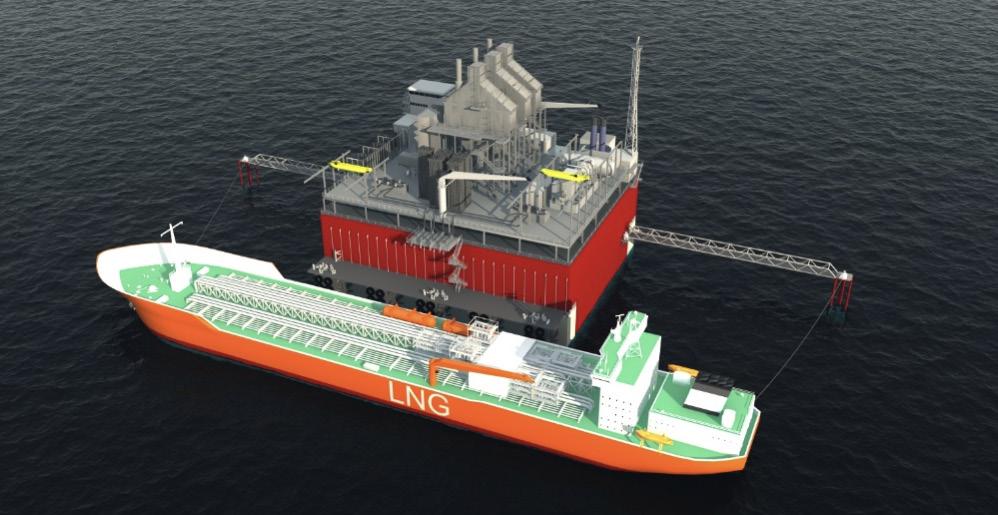
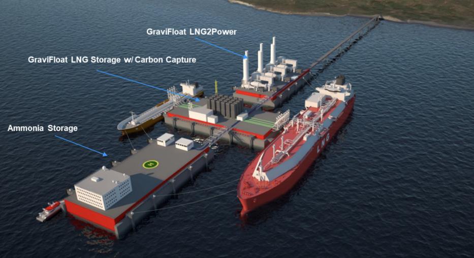
facility is typically 25 years or more, and there will be no requirement for dry-docking during its lifetime.
The efficient functionality is driven by storage availability for use when required. This reliability and safety of GraviFloat comes from two primary attributes: it is a semi-submerged structure fixed to the seabed, that relies on buoyancy forces to counteract permanent loads and it will come with a built in, conventional fixed jetty for berthing of visiting LNG carriers. GraviFloat, being a fixed structure, does not rely on a mooring system, but is kept in place by its fixed foundation.
Furthermore, multiple GraviFloats can be configured such that it shields the LNG carrier when it is berthed on the leeward side of it. Multiple GraviFloats can be placed facing towards the predominant wave forces and the structures effectively will act as a breakwater to dampen the wave action (Figure 4). Consequently, GraviFloat storage is expected to have a higher operability envelope when hosting a power generation package on the topside of the deck (Figure 2).
The term modularity is applied throughout the facility right from the cargo containment system to the regasification skid, liquefaction process unit, power generation package, and even the deck structures which are built in modules favouring the project construction schedule.
The promise of re-deployment is realised by dismounting the Gravifloat from the Gravidock after minor refurbishments. This terminal can be further scaled-up in a modular fashion as well, via the deployment of more such units adjacent to one another.
Lastly, considering the global transition towards low carbon emission, GraviFloat, can be built to accommodate carbon dioxide, ammonia, or hydrogen tanks, allowing carbon capture and decarbonised alternative fuels for various decarbonised topside applications.
Multiple GraviFloats can be configured for multiple applications as depicted below to offer flexibility in achieving different decarbonisation targets: an LNG receiving terminal plus carbon capture, an LNG-hydrogen-to-power facility and ammonia storage facility (Figure 3). Ultimately, like all the marine/offshore assets, GraviFloat provides property on the water to develop fit-for-purpose plants and additionally, it offers onshore operational and safety reliability with efficient construction and installation solution.
Conclusion
The GraviFloat terminal, developed by Seatrium, is a highly efficient and safe solution for scalable fixed LNG import and export terminals. It can be constructed efficiently in shipyards, similar to floating FLNG/FSRU conversion solutions. With full spectrum capabilities in marine and offshore energy solutions, Seatrium leverages engineering excellence centres in Singapore, Norway, and the US. This allows for early engagement with customers and project developers to identify requirements and deliver suitable solutions. The GraviFloat terminal, in addition to conventional floating and fixed bottom solutions, offers unique features and cost effectiveness throughout the total lifecycle of small scale LNG projects.
52 April 2024
Figure 1. FLNG Gimi
Figure 2. LNT-to-power GraviFloat without combined cycle gas turbine.
Figure 4. GraviFloat’s shielding and fixed attribute.
Figure 3. GraviFloat components.
NORTH AMERICA
A supplement to LNG Industry

Distributed at

Our North American supplement is returning soon!
This special issue will focus on LNG activity in the US, Canada, and Mexico, with keynote articles, case studies, and more.

Visit our website today: www.globalhydrogenreview.com The home of the latest hydrogen news, analysis and events

Cathy Farina, General Manager Product Development, PolaireTech International Inc., and Aditya Hegde, General
Manager, Polairetech
India Private Ltd,
explore how small scale LNG is gaining popularity in unlocking and commercialising local stranded gas resources, enabling a sustainable transition to cleaner energy.
atural gas, particularly in its liquefied form (LNG), has emerged as a preferred fuel across various sectors due to its cleanliness and cost-effectiveness. With significantly lower carbon emissions compared to oil and coal, as well as zero sulfur content, natural gas presents a compelling option for power generation, industrial processes, and domestic heating. The capital cost advantage of gas-fired power plants over coal-fired units further solidifies its position in the energy market.
Natural gas poses a challenge due to its lower energy density compared to conventional fuels. Consequently, it necessitates cryogenic cooling to approximately -162˚C, resulting in a volume reduction of around 600 times. This process facilitates easier storage and transportation in its liquid form. As the world transitions towards cleaner energy sources, LNG serves as a vital bridging fuel, providing a low-carbon alternative while renewable energy technologies continue to develop and deploy. The expanding use of LNG in new markets such as bunker fuel
55
and transportation fuel reflects the growing environmental concerns regarding carbon, nitric oxide, and sulfur emissions.
Currently, the majority of LNG production occurs in large scale facilities with significant economies of scale serving well connected gas sources. However, with the growing demand for cleaner energy sources, small scale LNG plants are enabling commercialisation of stranded gas resources like biogas, flared gases, stranded gas, and coal-bed methane (CBM) fields. Small scale LNG plants focus on minimising lifecycle costs through the adoption of energy-efficient technologies and standardised modular designs. This approach enables smaller plants to target specific markets or regions where large scale LNG production may not be feasible or economically viable.
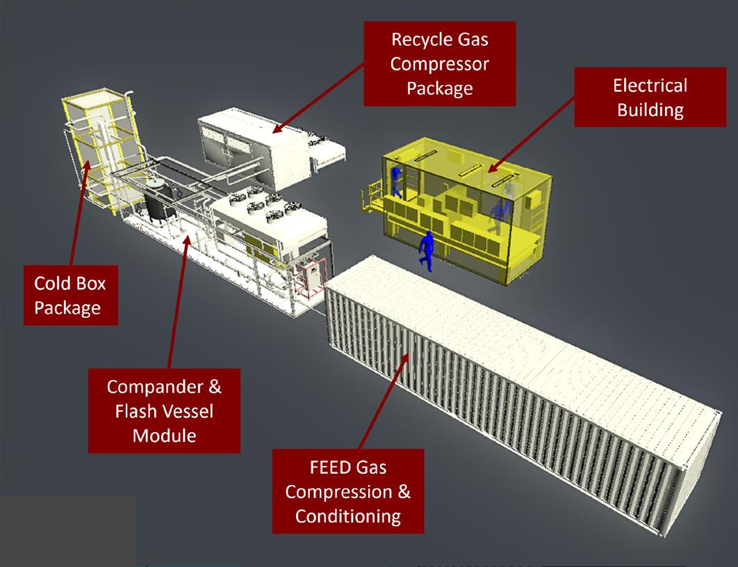
The rapid growth of the LNG market underscores its importance as a transition fuel in the global market. Its versatility, cleanliness, and cost-effectiveness position LNG as a key player in the journey towards a more sustainable energy future. This article will explore small scale LNG liquefaction technologies and their advancements, particularly those that offer solutions such as open methane zero refrigerant systems and utilising lean standardised modular methods.
Small scale LNG technologies
Small scale LNG technologies encompass a variety of processes and equipment designed to liquefy natural gas on a smaller scale, typically for niche markets or applications where traditional large scale LNG plants are impractical or economically unviable. Two basic refrigeration cycles have been used in LNG liquefaction scheme namely expander cycles and vapour compression cycles.
Vapour-compression cycles
These technologies depend on hydrocarbon liquids (refrigerant) absorbing heat as they transition from a liquid to a gas state. Within LNG plants, liquid refrigerants circulate in a closed loop, undergoing compression, liquefaction, and subsequent evaporation in a heat exchanger against the feed natural gas. This process cools and liquefies the natural gas. Historically, refrigerant cycles consisting of hydrocarbon mixtures or multiple cascaded single-component hydrocarbon refrigerant loops have been employed efficiently for large scale LNG plants; however, due to the process complexity, safety concerns, low efficiency, and high number of equipment required, these are not preferred for small scale applications.
In the case of standalone small scale LNG plants, nitrogen expander cycles are dominant, being offered by several companies. Propane vapour compression cycle 5000 tpy modular plants are also available at a relatively low capital cost but at a much lower methane-to-LNG conversion, resulting in a high lifecycle cost unless the feed gas is inexpensive.
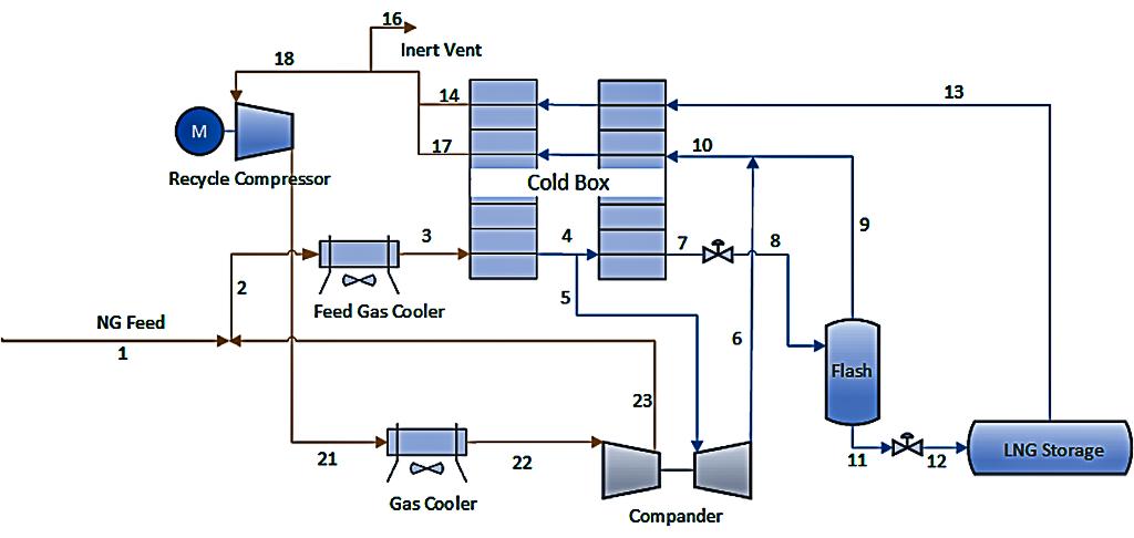
While methane expansion technologies have been used widely for peak shaving on gas pipelines, small scale stand-alone methane expander plants are only coming onto the market now. The methane expander cycle technology clearly offers the best option for future small and micro scale LNG based on the thermodynamic advantage of methane and innovative compact and simple process design increasing the overall efficiency, as well as very efficient small expanders becoming available.
Zero refrigerant utilising an open methane loop is a newer methane expander cycle technology that can obtain higher product yield and utilises energy efficient liquefaction processes. It is tailored for small scale applications
56 April 2024
Figure 1. 5000 tpy standard modular LNG plant layout.
Figure 2. Open methane zero-refrigerant simplified flow diagram.
Figure 3. Lean design process.
with best in class liquefaction yield, lower energy consumption and a flexible feed gas range.
Expander cycles
Expander-type liquefaction processes are particularly suited for small scale LNG plants due to their inherent advantages, including simplicity (resulting in lower equipment count), ease of start-stop operation, and the ability to be constructed within standardised skids for convenient transport to remote locations.
1. Nitrogen expander processes: Historically, nitrogen expander processes have been utilised primarily in small capacity LNG plants due to their relatively lower efficiency. Efficiency enhancements can be achieved by incorporating additional expanders (single, double, or triple) into the system, where the nitrogen (refrigerant) circulates in a closed loop and requires regular makeup to replenish the nitrogen inventory.
2. Methane expander processes (zero refrigerant): Methane expanders find application in low-capacity, peak-shaving LNG plants. Compared to nitrogen expander cycles, methane expander cycles offer a fundamental advantage because methane has a higher specific heat, resulting in reduced gas flows within the system. This reduction translates to lower power demands, necessitating smaller compressors, vessels, and pipes. Similar to nitrogen, multiple methane expanders can be arranged in series to enhance process efficiency. Notably, methane expanders utilise the methane present in the feed gas
for refrigeration, eliminating the need for external refrigerant supply.
Open methane zero refrigerant technology case study
Open methane zero refrigerant technology reduces the capital and operating costs in small scale LNG production, limiting the quantity of equipment required. The technology offers the following additional advantages over conventional process schemes:
z No refrigerant storage and transfer systems.
z No make-up refrigerants required.
z High LNG product yield (92% methane efficiency).
z No additional chemicals required (zero-chemical).
z No waste aqueous steams.
z Continuous process.
z Feed gas flexibility.
z Operational simplicity.
z Lower power demand.
z Capital cost savings.
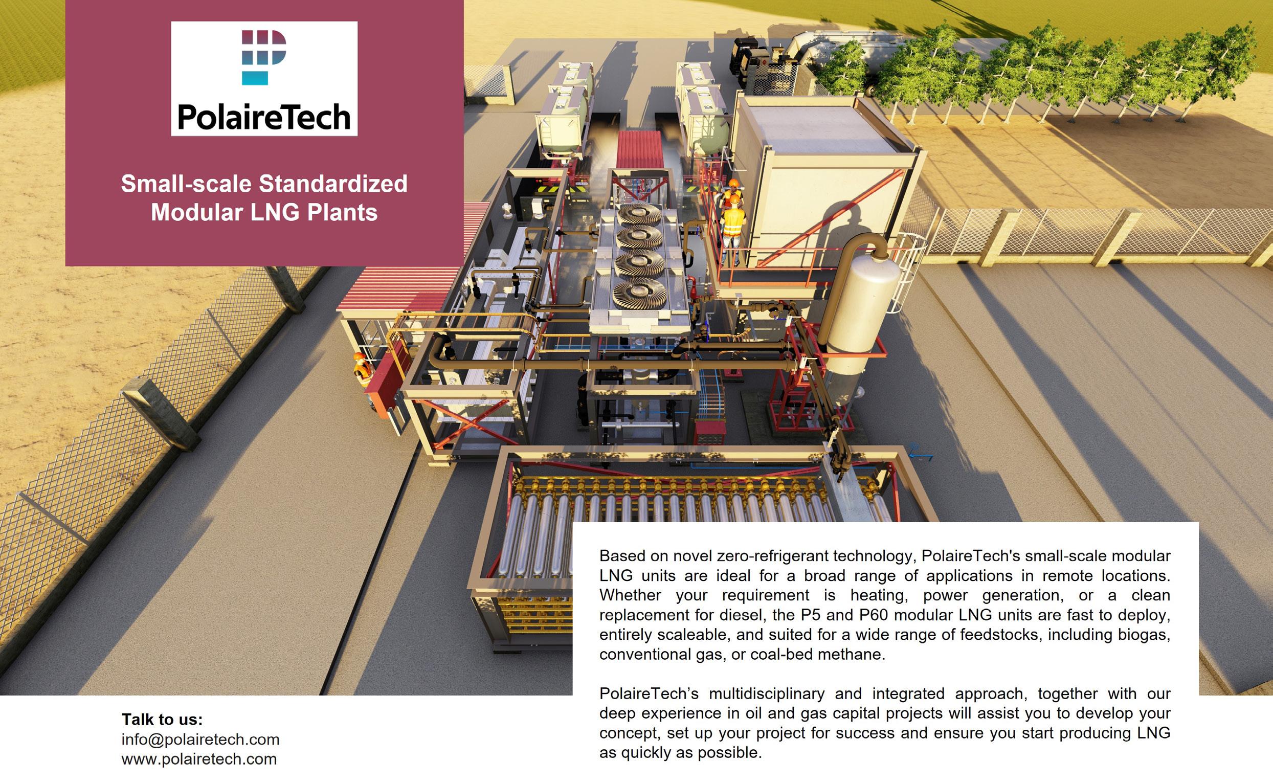
z Energy efficient liquefaction process.
z Efficient nitrogen removal due to the dual flash system.
z Shorter implementation schedules.
The design is based on ambient air to cool process streams, eliminating the need for cooling water. Furthermore, no hot utility, chemicals or refrigerant make-up is required. Operation in remote locations is therefore much simpler.
Figure 1 is an illustration of a 5000 tpy small scale standard plug-and-play modular plant.
The technology relies on innovative, economical, reliable, and efficient zero-refrigerant process. The natural gas is cryogenically cooled through an open-loop methane system, a distinctive feature in the industry. This streamlined approach decreases complexity, equipment numbers, power demands,
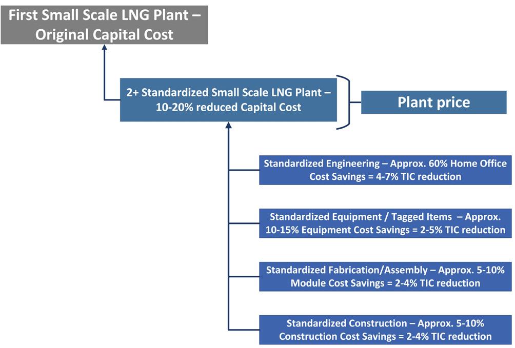
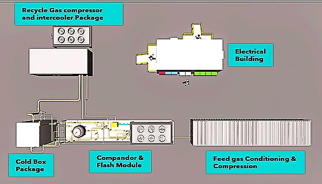
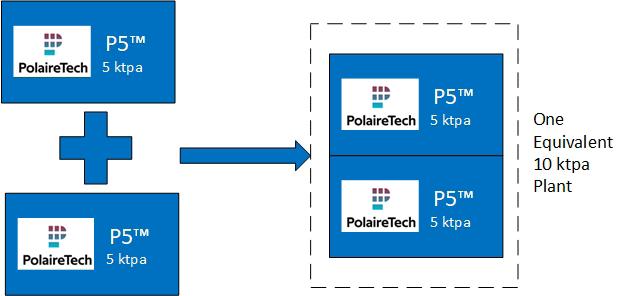
and maintenance expenses. Figure 2 illustrates a simplified flow diagram of a zero-refrigerant system.
The feed gas is initially cooled in the cold box by the exiting expanded cold natural gas streams. Part of this cooled gas is expanded to a lower temperature and pressure before being fed to the cold box to cool the remaining cooled gas stream. The cold box is a compact multi-stream brazed aluminium heat exchanger insulated with perlite.
The cold stream from the cold box is fed to the LNG flash section where the pressure is reduced, reducing the temperature further and then fed into the flash drum where the liquid and vapour fractions are separated. The methane-rich gas (flash gas) from the flash drum is then recycled back into the cold box to cool the methane-rich gas from the feed gas section. A purge stream from the LNG storage tank is required to maintain acceptable nitrogen concentrations in the final product. This vent stream can be vented to existing flare or used as fuel gas to generate power or other requirements. The unliquefied gas is re-circulated back into the system by the recycle compressor and compander mixed with the feed gas, maximising the methane conversion efficiency.
Lean standardised modular design
In addition to the process technology, small scale LNG plants need to apply lean standard modular methods to be competitive, cost effective and economical. The following will describe the lean design, standardisation and modularisation methodologies that should be applied to small scale LNG plants.
Lean design methods
The objectives of lean design and manufacturing encompass enhancing product quality, eliminating unnecessary waste, minimising production duration, and lowering overall costs. In developing a design with the lowest lifecycle cost, lean design principles are followed. This approach aligns with the business case and provides the most competitive solution. The lean design process employed in the development of micro and small scale LNG plants is depicted in Figure 3.
Standardisation (design one, build many)
The aim of standardisation is to establish a consistent level of uniformity across specific design capacities and standards within the chosen environment. Standardisation was deemed a crucial approach to lowering capital costs, minimising overall schedules, and reducing the lifecycle expenses of the plants. Embracing standardisation aligns with the ‘design one, build many’ philosophy and typically yields capital cost savings of 10 – 20%, as depicted in Figure 4.
Modularisation
Modular plant design offers scalability, adaptability, and plug-and-play units, facilitating seamless integration with existing systems while reducing on-site construction man-hours. Additionally, modular plants boast a compact footprint, optimising space utilisation.
Implementing a modular solution yield benefits such as reduced capital costs, driven by enhanced labour productivity and decreased key quantities. Principles of modularisation, including module definitions and basic layouts, were established during the plants’ development phase.
58 April 2024
One equivalent 10 000 tpy plant
Figure 6. Plant layout with combinations of two P5 plants.
Recycle
Compandor
flash
Feed gas conditioning & compression Cold box package
Figure 4. Standardised (‘design one, build many’) concept. Electrical building
gas compressor and intercooler package
&
module
Figure 5. Plant layout for 5000 tpy zero refrigerant small scale LNG plant.
Modular layouts aim to achieve a high level of modularisation, typically around 70 – 75%, indicating the amount of labour moved offsite compared to traditional stick-built designs. Transportation constraints will need to be carefully considered to ensure compatibility with most global inland transportation corridors.
The adoption of modularised plants typically leads to capital cost savings of around 15% compared to traditional stick-built executions. However, the cost savings may vary depending on factors such as craft labour costs and site productivity. Figure 5 illustrates the open methane zero refrigerant plug-and-play module layout.
Plug-and-play flexibility
The utilisation of lean-designed, standardised, modular units enables the construction of multiple plants employing standardised, plug-and-play process and/or utility modules. Each standard process module can be effortlessly integrated based on specific operational needs. For instance, in scenarios where local power is unavailable and power generation becomes necessary, the appropriate electrical generator blocks can be seamlessly incorporated into the facility. On-site LNG storage can similarly be expanded by adding standard storage units, while utilities can be augmented through the integration of standard utility modules.
Plug-and-play modular plants offer the advantage of flexibility and scalability. For example, as depicted in Figure 6, a P5 module can be easily combined with another module to create a 10 000 tpy capacity LNG plant. If a larger 20 000 tpy capacity plant is required, it is straightforward to configure four P5 modules in a cost-effective arrangement.
Lean execution schedule
Implementing a standardised design for a small scale LNG plant can lead to a significant reduction in the overall execution schedule, typically by 40 – 50% compared to traditionally executed similar facilities. The repeatability of this schedule largely hinges on the timely delivery of long-lead items. Establishing an offtake of multiple units can further expedite the repeatable schedule, driving additional reductions in project timelines.
Conclusion
As the global shift toward cleaner energy accelerates, LNG plays a crucial role as a transitional fuel, offering a low-carbon alternative while renewable energy technologies advance. The increasing demand for cleaner energy, particularly natural gas, creates an opportunity for the commercialisation of stranded gas resources such as biogas, flared gases, and CBM fields. In areas where large scale LNG plants may not be feasible or economically viable, smaller scale LNG plants become essential, prioritising the minimisation of lifecycle costs.
The open methane loop expander cycle technology provides an innovative and straightforward solution tailored for small and micro scale LNG applications, aimed at minimising plant lifecycle costs. Its thermodynamic advantage with methane, along with a compact and simple process design, enhances overall efficiency, resulting in higher product yields. This technology utilises energy-efficient liquefaction processes and a minimal number of equipment, all packaged within a standardised modular solution for easy plug-and-play installation.
Advertiser Page Alleima IBC AMECO 45 Asia Turbomachinery & Pump Symposium 2024 28 Aspen Aerogels IFC Baker Hughes OFC, 17 Black & Veatch 07 CB&I 21 Corban Energy Group 09 EffecTech 25 Elliott Group 04 Gas and Heat SpA OBC Advertiser Page Global Hydrogen Review 54 LNG Industry 22 LNG Industry North America 53 Matrix Service Company 27 OPW Clean Energy Solutions 37 PolaireTech 57 Stirling Cryogenics 13 Svanehoj 41 TB Global Technologies Ltd 31 Zipfluid 33 Zwick Armaturen GmbH 02
www.lngindustry.com LNG Industry is audited by the Audit Bureau of Circulations (ABC). An audit certificate is available on request from our sales department.
ADINDEX
15FACTS
Rystad expects Western Canadian gas output to increase to 19.9 billion ft3/d in 2024
Liquefaction capacity is expected to expand to 20 million tpy in 2030
The maple leaf has been the symbol of Canada since the 1800s
The Shell-operated LNG Canada Phase 1 is 85% complete, and will begin start-up activities over the next 12 months
Woodfibre LNG officially commenced in 3Q23, with operations due to start in 2027
The Hawaiian pizza was invented in Canada
Canada’s national animal is the beaver
The Coastal GasLink pipeline was mechanically complete in November 2023, ahead of its year-end target
The coldest ever recorded temperature in Canada is -63˚C
Canada is the second-largest country in the world
Canada has the longest coastline in the world, measuring 200 000 km
Only 0.5% of the world’s population lives in Canada
There is a polar bear jail in Churchill, Manitoba
Canada’s lakes and rivers contain about 20% of all fresh water on Earth
Canada became an independent nation in 1931
...ON
CANADA
60 April 2024
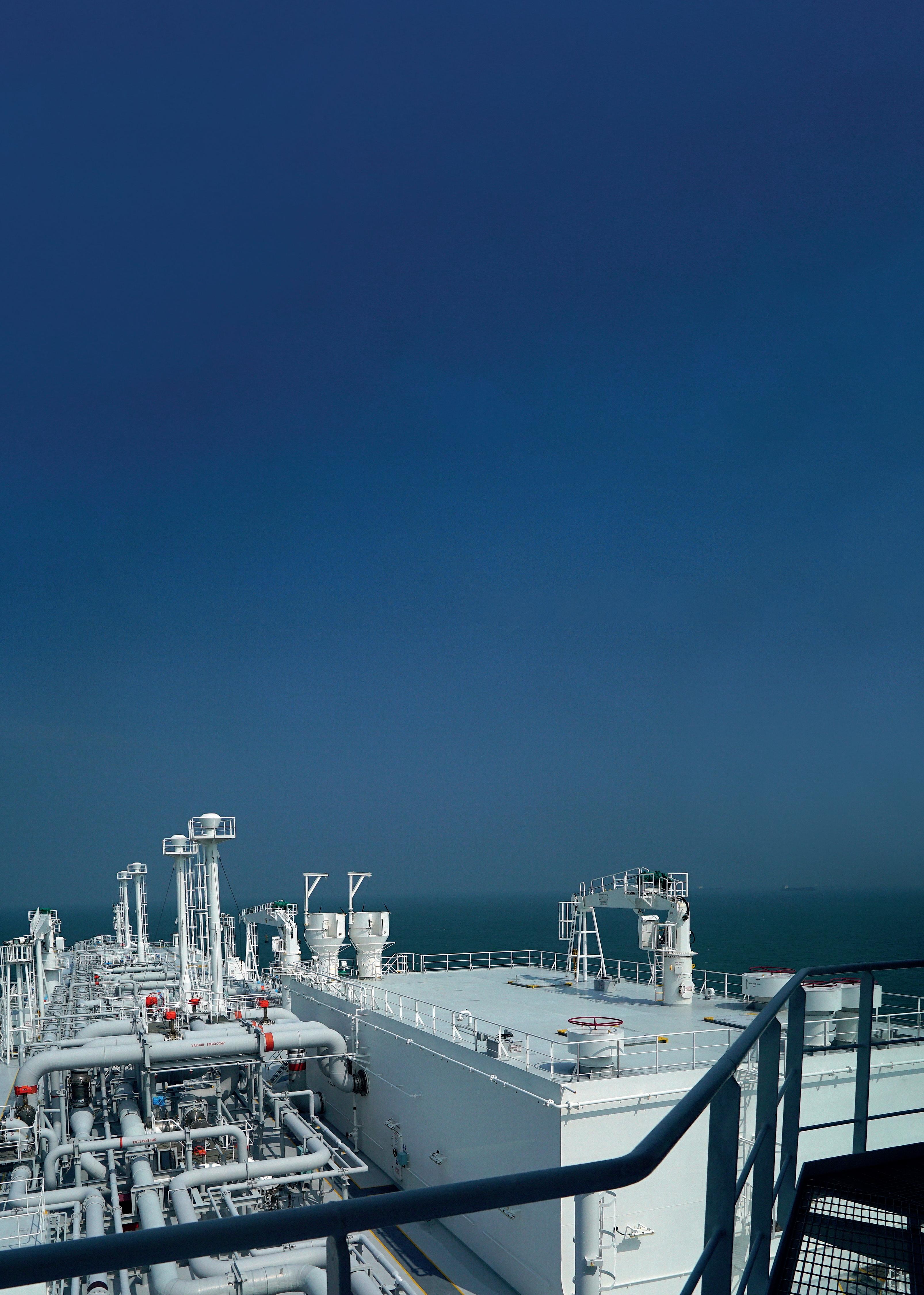
How to extend the lifetime of your LNG vaporizer
Increasing demand for LNG, gas and hydrocarbons is placing tough materials demands on heat exchangers in LNG re-gasification terminals. Your LNG vaporizers may be exposed to shell-and-tube fouling and extra maintenance due to corrosive seawater and cryogenic conditions.
This is where Alleima, the materials experts in advanced stainless-steel tubing and special alloys can help. With 60+ years in LNG and offshore natural gas, we extend the life of your vaporizers and other equipment by combating tough cryogenic and corrosive conditions.
Ask about our LNG-grade tube Sanicro® 35, an economical super-austenitic (highly alloyed) seamless stainless tube with high corrosion resistance and good weldability. Sanicro® 35 is produced with 83% recycled steel in a sustainable mill process. Sound interesting? Let’s talk!
alleima.com