June 2024


Don’t let foulants in your feedstock devalue your fi nal product. Get more out of your reactor with ActiPhase® technology. Our proven filtration system has a unique, active component that changes soluble foulants into solids, locking them away in its reticulated chambers so they can’t break out. That’s the Crystaphase Experience.


crystaphase.com

38 Conquering challenging applications
or languish
Gordon Cope, Contributing Editor, discusses the state of oil and gas markets in South and Central America and considers how countries can realise their energy potential amongst political storms.
14 Navigating low product demand: part one
In the first part of a two-part article, Scott Baker, Ram Paul Bajaj and Ross Storey, Shell Catalysts & Technologies, alongside Marc Donnelly, Eickmeyer & Associates, consider the operational challenges facing ethylene oxide operators as a result of low turndown, and the short-term solutions that are available.
19 An essential step
Jaap Bergwerff, Ketjen, explains why the hydroprocessing of waste plastic oils is an essential technology in the chemical recycling of waste plastics.
23 Cracking the case of hydrocarbon catalysis
Taco van der Maten, Malvern Panalytical, the Netherlands, discusses the use of X-ray diffraction (XRD) as a valuable tool for catalyst characterisation.
26 Maximising precious metal catalysts
Bradford Cook, Sabin Metal Corp., USA, outlines best practice control points for refiners looking to maximise the value and lifecycle of precious metals catalysts.
33 Growing value through collaboration
Virginie Bellière-Baca, Sulzer Chemtech, discusses customer partnership, innovation, and the endless evolution of technology in the downstream industry.


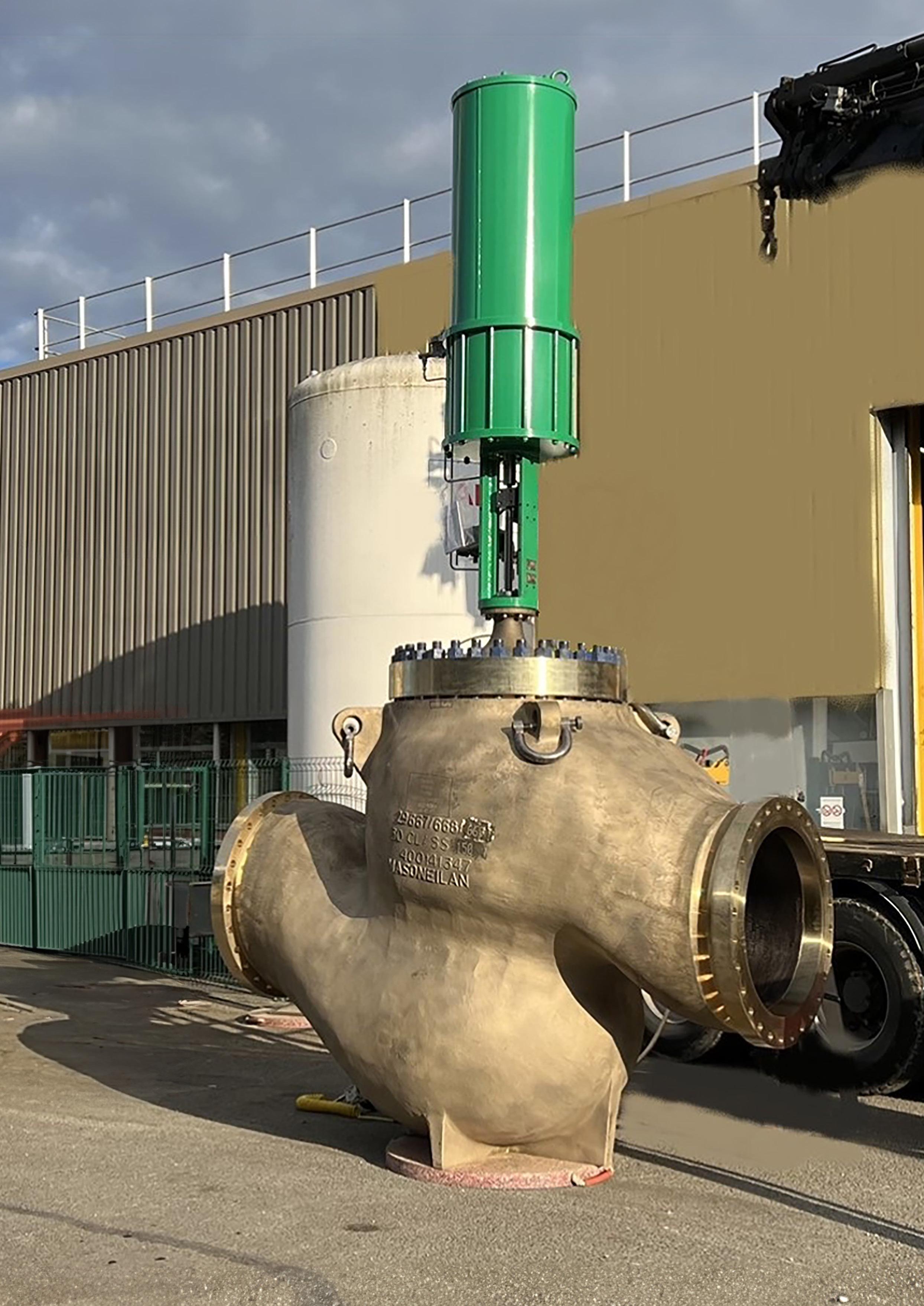
Rebecca O’Donnell and Raghavendran Mahalingam, Baker Hughes, explain why the hot high pressure separator let down valve solution is one of the toughest applications in the hydroprocessing process.
43 Seawater solutions
Desalinated seawater can serve as a reliable alternative to freshwater for industrial plants, but challenges abound. Gregory Gedney and Dave Noblin, Greene Tweed, USA, explain.
45 Advanced thermal reactor inspection
Martin McCallister, Delta Controls Corp., USA, explains how a process inspection camera designed for continuous online inspection of SRU thermal reactors can help operators monitor the performance of units.
51 Smooth operations
Christian Chanel, Integrated Global Services (IGS), USA, presents a guide to optimising convection section performance in ethylene furnaces.
55 Fuelling the future
E. M. Ishiyama, D. Oakley, J. Kennedy, S. J. Pugh, and H. U. Zettler, Heat Transfer Research Inc. (HTRI), discuss the advantages that digital innovations can offer in tackling challenges faced by contemporary refineries during the energy transition.
61 Paving the way for greener systems
Chelsea Hogard, Watlow, USA, considers the importance of data insights in mitigating the risks associated with process heating and aiding the transition to more efficient systems.
65 Intelligent plants
C. Brighenti, A. Brighenti and M. Ricatto, S.A.T.E., Italy, explain the journey to increased autonomy for hydrocarbon processing plants.
72 Q&A with...
Hydrocarbon Engineering talks to Dr. Matthias Schwab, Director of New Business Development & Sustainability, BASF Process Catalysts.
Hydroprocessing, integral to downstream oil and gas refining, aims to eliminate detrimental components like sulfur and nitrogen from crude. Valves play a critical role in these operations, requiring careful consideration due to extreme conditions. Turn to p. 38 to learn which solutions address these challenges with innovative designs and material selections, ensuring longevity and reliability.

CONTENTS June 2024 Volume 29 Number 06 ISSN 1468-9340 THIS MONTH'S FRONT COVER CBP019982 Hydrocarbon Engineering Like Join Hydrocarbon Engineering @HydrocarbonEng Follow CONVERSATION JOIN THE 2024 Member of ABC Audit Bureau of Circulations Copyright© Palladian Publications Ltd 2024. All rights reserved. No part of this publication may be reproduced, stored in a retrieval system, or transmitted in any form or by any means, electronic, mechanical, photocopying, recording or otherwise, without the prior permission of the copyright owner. All views expressed in this journal are those of the respective contributors and are not necessarily the opinions of the publisher, neither do the publishers endorse any of the claims made in the articles or the advertisements. Printed in the UK. 03 Comment 05 World news 08
Flourish


Cut your CO2 emissions in half with ET Black™ Carbon Black Technology
ET Black™ is a state-ofthe-art technology that complies with the most stringent environmental regulations now and in the future. Plus, the flexibility to produce all ASTM grades, and specialty grades, in a single plant. ET Black™, the technology of reference for producing carbon black obtained by thermal decomposition of highly aromatic oils.
Find out more at: www.igoforETBlack.com

CONTACT INFO
MANAGING EDITOR James Little james.little@palladianpublications.com
SENIOR EDITOR Callum O'Reilly callum.oreilly@palladianpublications.com
EDITORIAL ASSISTANT Poppy Clements poppy.clements@palladianpublications.com
SALES DIRECTOR Rod Hardy rod.hardy@palladianpublications.com
SALES MANAGER Chris Atkin chris.atkin@palladianpublications.com
SALES EXECUTIVE Sophie Birss sophie.birss@palladianpublications.com
PRODUCTION MANAGER Kyla Waller kyla.waller@palladianpublications.com
EVENTS MANAGER Louise Cameron louise.cameron@palladianpublications.com
DIGITAL EVENTS COORDINATOR Merili Jurivete merili.jurivete@palladianpublications.com
DIGITAL CONTENT ASSISTANT Kristian Ilasko kristian.ilasko@palladianpublications.com
DIGITAL ADMINISTRATOR Nicole Harman-Smith nicole.harman-smith@palladianpublications.com
ADMIN MANAGER Laura White laura.white@palladianpublications.com
CONTRIBUTING EDITORS Nancy Yamaguchi Gordon Cope
SUBSCRIPTION RATES
Annual subscription £110 UK including postage /£125 overseas (postage airmail).
Two year discounted rate £176 UK including postage/£200 overseas (postage airmail).
SUBSCRIPTION CLAIMS
Claims for non receipt of issues must be made within 3 months of publication of the issue or they will not be honoured without charge.
APPLICABLE ONLY TO USA & CANADA
Hydrocarbon Engineering (ISSN No: 1468-9340, USPS No: 020-998) is published monthly by Palladian Publications Ltd GBR and distributed in the USA by Asendia USA, 701C Ashland Avenue, Folcroft, PA 19032. Periodicals postage paid at Philadelphia, PA & additional mailing offices. POSTMASTER: send address changes to HYDROCARBON ENGINEERING, 701C Ashland Ave, Folcroft PA 19032.
COM MENT

great summer of sport is just around the corner. 2024 brings the return of the Olympic Games to Paris after exactly 100 years and on Friday 14 June, Germany will open its doors to a mass of frenzied football fans from across the continent as it hosts the UEFA European Championships. After football’s international governing body, FIFA, misleadingly promoted the 2022 Qatar World Cup as ‘carbon neutral’ – a strategy which attracted criticism from advertising authorities that found the supposed carbon offsetting measures to be problematic –UEFA, football’s European governing body, has pledged to make Euro 2024 the greenest football tournament to date. The tournament’s ESG strategy is backed by a €32 million investment, and no oil and gas companies have been selected as commercial partners. This stands in stark contrast to FIFA’s very recent announcement at the end of April of its new sponsorship deal with the largest oil and gas company in the world, Saudi Arabia’s Aramco.
A15 South Street, Farnham, Surrey GU9 7QU, UK
Tel: +44 (0) 1252 718 999
Key to its aim for Euro 2024 to become the reference point for climate-responsible sporting events, UEFA has urged national teams to strongly consider travelling between fixtures by bus or train, rather than opting for heavily polluting domestic flights. The match schedule has been adapted to promote shorter distance journeys in the tournament’s group stage, and free public transport is being offered to ticket holders in an attempt to reduce the carbon footprint of spectators. Following through on these measures will be key to UEFA’s reputation as a sustainable sporting governing body following last year’s decision to expand European club football and schedule an additional 177 fixtures across three tournaments in the 2024-25 season – a choice which BBC Sport highlighted could result in teams and fans travelling a total of approximately 2 billion air miles.¹
However, the downstream industry is progressing when it comes to making our planet’s skies cleaner. At the heart of this progress is the role of catalysis and the development of higher quality catalysts to develop more efficient pathways for the transformation of feedstocks into sustainable aviation fuel (SAF). As just one example, last year, ART, a joint venture (JV) of Chevron and Grace, launched a hydroprocessing catalyst solution to produce renewable diesel and SAF from 100% renewable sources, such as vegetable oils, refined oils, animal fats, and greases. Today, it is clear that continued innovation has never been more important, and the development of modern catalyst technologies will be vital in meeting increasingly stringent emissions reduction targets. Articles in this issue from Shell Catalysts and Technologies, Malvern Panalytical and Ketjen dive into the invaluable role of catalysts in the downstream industry, and explore the role that they will play in a more sustainable future.
With the mounting pressure to decarbonise affecting all corners of the industry, collaboration and partnerships will be key in the transition, a topic which is explored in more detail on p. 33 of this issue by Sulzer Chemtech. As UEFA has stated, ‘only in unity’ can the power of football as the most popular sport in the world be leveraged to successfully spread a sustainable message.² And only through collaboration and continued innovation will the downstream industry create a greener future.
This month, the city of Frankfurt in Germany will not only be one of 10 host cities of UEFA’s Euro 2024, but also to ACHEMA, an event which aims to foster sustainable connections in the process industries. If this is where you are picking up this copy of the magazine, you can register to Hydrocarbon Engineering for free by scanning the QR code and keep up-to-date with the downstream industry’s energy transition.

1. https://www.bbc.co.uk/sport/football/67159156#:~:text=BBC%20Sport%20research%20 suggests%20the,1.5%20billion%20in%202022%2D23.
2. ‘Our strategy for a sustainable UEFA Euro 2024’, UEFA, (July 2023).
POPPY CLEMENTS EDITORIAL ASSISTANT


WORLD NEWS
Hungary | MOL inaugurates polyol complex in Tiszaújváros
MOL Group recently held an inauguration ceremony in Tiszaújváros to celebrate the completion of its polyol complex, which boasts a capacity of approximately 200 000 tpy of polyol.
MOL, thyssenkrupp and Evonik IP signed the licence agreement for the complex in summer 2017, and the foundation stone was laid in September 2019.
The main units were transported to Tiszaújváros between 2019 and 2020, mainly by water, and were followed by the completion of the complex’s hydrogen peroxide, propylene oxide, polyol and propylene glycol plants.
The Tiszaújváros plant will produce polyol using one of the most efficient and environmentally friendly methods available today.
UK | Stanlow Refinery celebrates centenary
EET Fuels (formerly Essar Oil UK), which owns and runs the Stanlow Manufacturing Complex, recently celebrated the 100 th anniversary of the Stanlow Refinery.
Established in 1924 as a bitumen production site, Stanlow has been a vital pillar of the UK’s energy sector for a century, providing essential products and transportation fuels, and supporting the nation’s economic growth.
The centenary celebration will encompass a series of events and initiatives that recognise Stanlow’s significant contribution to the Cheshire community, the local region, and the country as a whole. At the same time, the company will use the centenary to recognise, celebrate and give thanks to the communities connected to Stanlow, while demonstrating its long-term commitment to support these communities into the future.
USA | AFPM announces winners of Annual Safety Awards
The American Fuel & Petrochemical Manufacturers (AFPM) has announced the winners of its 2023 Annual Safety Awards. These awards are part of a comprehensive programme developed by the AFPM Safety and Health Committee to promote safe operations in the refining and petrochemical industries, and to recognise facilities that have outstanding occupational and process safety performance.
The highest honour, the ‘Distinguished Safety Award’, is awarded to the top sites with outstanding safety performance, programme innovation, and safety leadership. This honour was awarded to four facilities for achieving a sustained, exemplary level of safety performance: Marathon Petroleum Co. (Canton Refinery); Marathon Petroleum Co. (Robinson Refinery); Phillips 66 (San Francisco Refinery) and Phillips 66 (Sweeny Refinery).
Global | Ethylene downcycle puts 24% of global capacity at some risk of closure
Aseries of unprecedented challenges to the global ethylene industry means that as much as 24% of global capacity is now under some threat of permanent closure, according to new research by Wood Mackenzie.
The report ‘Global Steam Cracker Closure Threat 2024’ states that 114 assets out of 330 screened are at some risk. This represents around 55 million tpy of 2023’s total global ethylene capacity with more than half of that figure being at a medium or high risk of closure.
“The global ethylene industry is currently navigating a downcycle,” said Alan Gelder, Vice President of Refining and Chemicals Research at Wood Mackenzie. “The industry has faced multiple headwinds and uncertainties, stemming from a global pandemic, the Russia-Ukraine and Israel-Hamas conflicts, an economic downturn and significant capacity overbuild.”
The report states that China’s strategy of phasing out small and aged facilities and replacing them with more cost-competitive and
energy-efficient crackers will have an impact domestically and across Asia.
Wood Mackenzie has identified 3.3 million t of Chinese ethylene capacity as being at high risk of closure and 2.4 million t as being at medium risk.
China’s increasing ethylene self-sufficiency will impact Northeast Asia producers the most, with 9 million t of capacity vulnerable to closure. The report adds that Southeast Asian crackers benefiting from advantaged feedstock will not be affected as negatively.
June 2024 HYDROCARBON ENGINEERING 5

WORLD NEWS
DIARY DATES
26 - 27 June 2024
Downstream USA
Galveston, Texas, USA events.reutersevents.com/petchem/downstream-usa
20 - 22 August 2024
Turbomachinery & Pump Symposia Houston, Texas, USA tps.tamu.edu
05 September 2024
World Energy Transition Conference
Virtual www.accelevents.com/e/worldenergytransition2024
17 - 20 September 2024
Gastech Houston, Texas, USA www.gastechevent.com
22 - 25 September 2024
GPA Midstream Convention San Antonio, Texas, USA www.gpamidstreamconvention.org
24 - 25 September 2024
IDW – Downstream Conference Warsaw, Poland www.europetro.com/idw
15 - 17 October 2024
AFPM Summit
New Orleans Louisiana,, USA summit.afpm.org
04 - 07 November 2024
ADIPEC
Abu Dhabi, UAE www.adipec.com
11 - 14 November 2024
ERTC Lisbon, Portugal
www.worldrefiningassociation.com/event-events/ertc
03 - 05 December 2024
Valve World Expo
Düsseldorf, Germany www.valveworldexpo.com
21 -22 January 2025
NARTC Houston, Texas, USA
www.worldrefiningassociation.com/event-events/ nartc
USA | Worley to support Bayou Bend CCS project
Worley has been selected to design and evaluate carbon dioxide (CO 2 ) gathering, handling and sequestration facilities for the Bayou Bend CCS LLC joint venture, located along the Gulf Coast in Southeast Texas, US.
The Bayou Bend project includes a CO 2 storage footprint of nearly 140 000 acres of pore space.
The Gulf Coast has one of the heaviest concentrations of CO 2 emissions in the US, making this project pivotal in enabling hard-to-abate industries, such as
refining, cement, steel, chemicals, and manufacturing, to meet their climate goals. Carbon sequestration along the Gulf Coast helps to support a broader national effort to reduce carbon emissions.
Mark Trueman, Group President, Americas for Worley, said:
“Innovative projects like Bayou Bend will potentially enable CCS at scale and help many more companies achieve their net zero goals, supporting Worley’s purpose of delivering a more sustainable world.”
Germany | BASF and IPP agree to market ammonia, methanol and melamine plants
BASF and International Process Plants (IPP) have entered an agreement to market ammonia, methanol and melamine plants located at BASF’s Verbund site in Ludwigshafen, Germany.
The plants have become available as BASF implements structural measures at its Ludwigshafen site to ensure competitiveness in a changing European market environment, as
announced in February 2023. BASF will continue to produce ammonia and methanol in other assets at the Ludwigshafen site. The two companies have agreed not to disclose financial details of the deal.
The agreement includes the integrated production assets for ammonia (380 000 tpy), methanol (165 000 tpy) and melamine (51 000 tpy).
China | TotalEnergies and SINOPEC strengthen cooperation
TotalEnergies and China Petroleum and Chemical Corp. (SINOPEC) have signed a strategic cooperation agreement to deepen their collaboration, notably in low-carbon energies.
TotalEnergies and SINOPEC have been working together for many years, notably in Angola and Brazil in upstream operations, and more generally in various domains such as oil, LNG, oil product trading, and engineering. Recently, the companies
have joined forces to develop a 230 000 tpy sustainable aviation fuel (SAF) production unit at a SINOPEC refinery in China.
This strategic cooperation agreement aims to further develop the partnership between TotalEnergies and SINOPEC, and seize new opportunities by leveraging their respective expertise. In particular, the two companies plan to combine their R&D expertise in biofuels, green hydrogen, CCUS and decarbonisation.
June 2024 HYDROCARBON ENGINEERING
6
Visit us at ACHEMA in Frankfurt Hall 4 Stand D48

Capturing green opportunities
Carbon capture and storage or utilization (CCS/CCU) is a key strategy that businesses can adopt to reduce their CO2 emissions. By selecting the right technologies, pressing climate change mitigation targets can be met while benefi tting from new revenue streams.
Sulzer Chemtech offers cost-effective solutions for solvent-based CO2 absorption, which maximize the amount of CO2 captured and minimize the energy consumption. To successfully overcome technical and economic challenges of this capture application, we specifically developed the structured packing MellapakCC™. This packing is currently applied in several leading CCS/CCU facilities worldwide, delivering considerable process advantages.
By partnering with Sulzer Chemtech – a mass transfer specialist with extensive experience in separation technology for carbon capture –businesses can implement tailored solutions that maximize their return on investment (ROI). With highly effective CCS/CCU facilities, decarbonization becomes an undertaking that can enhance sustainability and competitiveness at the same time. For more information: sulzer.com/chemtech


8 June 2024 HYDROCARBON ENGINEERING

Gordon Cope, Contributing Editor, discusses the state of oil and gas markets in South and Central America and considers how countries can realise their energy potential amongst political storms.
Over 650 million citizens occupy the region stretching from Mexico to Argentina, with another 100 million expected by 2050. Fortunately, the region is blessed with abundant oil and gas reserves to deal with growing demand; sadly, a wide disparity in the various nations’ ability and will to produce those reserves will mean some states will flourish, while others languish.
Guyana
Over the last decade, Guyana has been transformed from an impoverished nation to one of the world’s biggest oil and gas success stories. Offshore discoveries by ExxonMobil and partners in the Stabroek Block have resulted in an estimated 11 billion bbl of recoverable oil resources, with the potential for far more discoveries.
June 2024 9 HYDROCARBON ENGINEERING
In late 2023, ExxonMobil connected its latest floating production, storage and offloading (FPSO) vessel, named Prosperity , to the Payara project, boosting the country’s production to over 600 000 bpd. Projections call for a total of 12 FPSOs producing up to 1.5 million bpd by 2027.
While most production is destined for export, Guyana is keenly interested in developing its domestic economy. The offshore discoveries, for instance, contain a significant proportion of associated gas. In hopes of reducing expensive fuel imports, the government negotiated a US$1.9 billion gas-to-power project with ExxonMobil to monetise the gas. The project includes a US$1 billion pipeline that extends 225 km from the Stabroek block to a 300 MW power plant near Georgetown. ExxonMobil has almost completed the pipeline, but the power plant is about six months behind schedule, and government officials now expect it to come online in late 2025.
Venezuela
Venezuela sits at the opposite end of the spectrum in the region. With an estimated 304 billion bbl of reserves, the country has seen its output plummet from over 3 million bpd to an estimated 800 000 bpd in early 2024. Much of the problem can be attributed to mismanagement, corruption, and a lack of maintenance. The immense 940 000 bpd Paraguana refinery complex has been the scene of a score of failures. In mid-2023, the fluid catalytic cracker (FCC) at the complex’s Cardon refinery failed, resulting in the shutdown of gasoline production. While President Maduro makes frequent headlines promising a return to historic output, independent estimates suggest that the country’s once flourishing oil and gas sector would need at least US$200 billion to restore viability.
Brazil
Brazil is the Latin American powerhouse of oil and gas. By the end of 2023, thanks largely to the pre-salt play, total crude and gas production reached 4.7 million boe/d. State-owned Petrobras has announced plans for 11 new floating FPSO vessels through 2027 alone; analysts expect the country will exceed 5 million boe/d by the end of the decade.
The majority of the country’s production growth (almost 20% in the last two years), has been through state-controlled Petrobras. But now, with the election of Luiz Inácio Lula da Silva (Lula) in 2022, the company has taken a new approach. Under previous administrations, Petrobras had been divesting non-production assets (such as refineries, fertilizers and petrochemicals), to bring down its debt load. Under Lula, asset sales that have not been finalised have been suspended, and US$5.2 billion has been set aside to invest in solar and wind power over the next five years.
While critics say the changes are designed to increase political rather than economic capital, Petrobras is certainly not eschewing the latter. Its 2024 - 2028 budget plan stands at US$102 billion; US$73 billion is slated for
exploration and production, primarily in the pre-salt, as well as new frontiers in offshore equatorial regions in northern Brazil and West Africa.
In addition, Petrobras announced in January 2024 that it would finish expansion plans on Train One at its 100 000 bpd Abreu e Lima (RNEST) refinery, nearly a decade after the expansion was halted due to the massive ‘Car Wash’ corruption scandal. Train One will add 15 000 bpd capacity, while Train Two, slated to start in late 2024, will bring total capacity up to 260 000 bpd when work is finished in 2028.
IOCs and NOCs are also busy in the pre-salt. Shell, Ecopetrol and TotalEnergies recently contracted Modec to design a US$3 billion FPSO for its Gato do Mato discovery, located 250 km from Rio de Janiero at depths exceeding 2000 m. The discovery consists of light, low-sulfur crude with associated gas. Although the field is not fully explored, initial well tests indicate sufficient reserves to support 70 000 bpd production for several decades. While Shell already accounts for over 450 000 boe/d in production in Brazil, most is in minority partnerships with operator Petrobras. Being majority operator of a major offshore field would be a significant change for its operational profile in the country.
Argentina
Argentina’s Vaca Muerta shale play has been a resounding success. The basin in Neuquén province holds an estimated 16 billion bbl of recoverable oil and 308 trillion ft 3 of associated gas. In early 2024, unconventional production reached almost 400 000 bpd. The output has decreased the country’s reliance on imports, and the building of pipelines has spurred efforts to export associated gas to regional neighbours and tap into the lucrative international LNG market.
After decades of fiscal mismanagement, however, Argentina is in dire financial straits, and the play has become a political football. During Javier Milei’s successful run for Argentina’s presidency in 2023, the Libertarian made sweeping campaign promises to rear in government spending in an attempt to curb raging inflation. Part of his platform was to privatise over 40 state-run companies, including YPF, the national oil champion and prime investor in the Vaca Muerta.
When he tabled an omnibus package to congress in January 2024, however, YPF’s privatisation had been taken off the table, and Milei’s administration is currently weighing alternatives. YPF, which is 51% owned by the government, is investigating plans of boosting market capitalisation fourfold by the end of the decade by divesting conventional assets and focusing on the Vaca Muerta. By 2030, the play is expected to be producing 1 million bpd and up to 4 billion ft 3 /d of gas, generating up to US$20 billion in annual revenues.
Argentina still relies heavily on imported fuels, however. The country has approximately 600 000 bpd of domestic refining capacity; YPF accounts for around half, including the 189 000 La Plata refinery near Buenos Aires and the 105 000 bpd Lujan de Cuyo refinery in Mendoza. In 2019, the company announced that it would spend
June 2024 HYDROCARBON ENGINEERING 10


Grace, the global leader in FCC catalysts and additives, introduces MIDAS® Pro catalyst, for resid cracking in high iron applications.
This innovation, built on our workhorse MIDAS® catalyst platform, proved its capacity to handle even the worst Fe excursions. In commercial trials with multiple in-unit applications, MIDAS® Pro catalyst demonstrated sustained bottoms cracking in the face of iron spikes that measured among the highest in the industry. Diffusivity levels were consistently high, indicating no transport restrictions with concentration of Fe. This improved iron tolerance allows refiners to operate at higher iron levels which increases feed processing flexibility and profitability.
Talk with your Grace partner about the advantages of MIDAS® Pro catalyst today. Learn more at grace.com
MIDAS® Pro catalyst offers the solution for resid cracking in high iron environments. Gain feed flexibility with better bottoms upgrading.
Turn iron into gold? Alchemy? No. It’s chemistry.
more than US$2 billion to carry out a desulfurisation process at both plants and to increase production. By late 2023, the company was producing a record 310 000 bpd of gasoline and diesel, and expects to add another 20 000 bpd of output in 2024.
The growth in gas production is also expected to offer opportunities for LNG exports. The Vaca Muerta produced 2.7 billion ft 3 /d of associated gas in late 2023, and is expected to exceed 4 billion ft 3 /d by 2030. YPF has been working to establish a floating LNG (FLNG) plant in the Atlantic port of Bahia Blanca. It recently signed a memorandum of understanding (MoU) with Petronas to enter into an ambitious project that would, in addition to the FLNG plant, establish a 5 million tpy onshore plant. Ultimately, the two companies envision investing up to US$56 billion to create a 25 million tpy complex generating up to US$20 billion in annual exports.
Colombia
Colombia is South America’s third largest oil producer, with an output of over 700 000 bpd. Only eight years of reserves are left, however, and the country needs to significantly increase exploration in order to maintain production. The future of the country’s oil and gas sector was cast into doubt in September 2022, when Gustavo Petro was elected as new president. The left-wing candidate had run on a platform of eliminating contracts for oil and gas exploration and a ban on fracking. He lost little time stacking Ecopetrol’s board of directors with his own slate of candidates, one that would focus on a transition to renewables such as wind and solar. During COP 28 in late 2023, Petro also announced the country would invest US$32 billion in green transportation, clean energy and climate adaptation.
Reality is beginning to intrude, however. Fossil fuels represent a major portion of the government’s revenues, and the country can ill afford to turn its back on the sector. In late 2022, when President Petro visited the port of Barrancabermeja, the site of Ecopetrol’s century-old 250 000 bpd refinery, he stressed that Colombia’s future energy needs would be supplied by renewables. Ecopetrol had previously announced a US$780 million plan to upgrade the plant with an expansion of its hydrocracking unit. Petro’s speech placed the future of the plant in doubt, but, in mid-2023, Ecopetrol finally began work to improve fuel quality, develop blue and green hydrogen and carbon capture, utilisation and storage (CCUS).
Companies also continue to invest heavily in exploration. Ecopetrol and Petrobras are drilling the offshore Orcas Norte 1 appraisal well in the Tayrona block, hoping to tap into massive gas reserves in the area. Shell and Ecopetrol are drawing up plans to develop the Gorgon discovery in the ultra-deep-water COL-5 block. In the onshore Llanos region, Geopark and Hocol are pursuing several recent discoveries.
Mexico
For the last decade, Mexico’s oil and gas sector has been buffeted by political storms. When Enrique Pena Nieto
was elected in 2012, he eliminated the state monopoly in oil and gas and invited international operators to participate in upstream to downstream activities, resulting in billions of investments.
The honeymoon ended with the election of Andrés Manuel López Obrador (AMLO) in 2018. The president cancelled licencing rounds and limited Pemex’s JVs with deep-water explorers. Over the course of his presidency, AMLO has also made domestic self-reliance of fuels a priority. The country consumes around 1.6 million bpd of gasoline, diesel and jet fuel. Pemex owns six refineries with a capacity of approximately 1.5 million bpd, roughly enough to meet domestic demand. But output has historically been well below potential due to lack of maintenance, mismanagement and theft, and as a result, needs to import significant amounts of refined fuels to meet its needs.
To achieve self-reliance, Pemex has been spending significant capital to improve output; for instance, it earmarked US$2.6 billion in renovation funds for the 315 000 bpd Tula refinery near Mexico City, which has operated at half capacity for the last several years. Pemex is also commissioning its new Dos Bocas refinery in the state of Tabasco. A pet project of AMLO, the US$12.5 billion facility officially began operations in 2022, but is not expected to reach its 340 000 bpd capacity until 2025.
All this is having a beneficial effect. Pemex projects its 2023 rate of gasoline, diesel and jet fuel production of 655 000 bpd to climb to over 1 million bpd in 2024 as Dos Bocas comes on-stream, and upgrades and repairs at its other six refineries improve output. As a result, in April 2024, Pemex’s trading arm began cancelling export contracts for its benchmark Maya crude, a heavy, sour feedstock primarily used by USGulf Coast (USGC) refineries.
This creates a bit of a dilemma. While curtailing crude exports will provide the new Dos Bocas refinery with sufficient feedstock when it is finally completed, Tabasco has a shortage of natural gas, which could hinder production unless new gas pipelines to the Yucatan are completed over the next several years.
AMLO has not impeded gas exports, however, and the country’s LNG sector has great prospects, with over 60 million tpy either approved or seeking permits. In March 2024, Sempra announced that Phase 1 of its Energía Costa Azul (ECA) LNG project in Baja, California, would enter commercial operations by mid-2025. The 3 million tpy train will be serviced by Sempra’s 500 million ft 3 /d GRO line, with gas sourced in the US. When compared to competitors in the USGC, the site has a significantly reduced transit time to key Asian markets, and Sempra has plans to expand the former regasification terminal to 12 million tpy in Phase 2.
The proposed Mexico Pacific Ltd (MPL) LNG project is located south of ECA on the Sea of Cortez in Sonora State. The latest plan is to build three trains totalling 14.1 million tpy capacity in Phase 1, and a
June 2024 HYDROCARBON ENGINEERING 12
further three trains in Phase 2, doubling capacity to 28.2 million tpy.
The Biden administration’s pause on LNG development has complicated Mexico’s long-term LNG plans, however. In January 2024, the White House placed a temporary halt on permit approvals for LNG exports to non-free trade countries while the Department of Energy (DOE) reviews their environmental impact. The DOE also issues permits for LNG terminals in Mexico that would re-export natural gas from the US. While the pause does not impact ECA, it does place projects like MPL in doubt as potential investors weigh the impact.
Problems
A wide variety of above-ground complications abound within the many countries of South and Central America:
n Colombia, which relies on oil and gas for one-quarter of its revenues, can ill-afford missteps as it eschews fossil fuels in favour of green energy; protests from the disaffected poor and violence from guerrilla groups already engulf many parts of the country.
n Mexican President, AMLO, is backing former Mexico City Mayor, Claudia Sheinbaum, in this year’s federal election. She is heavily favoured to win, but it is unknown whether she will continue the populist politics of her mentor or strike her own path; this uncertainty raises investment risks.
n Guyana is embroiled in a controversy with Venezuela over ownership of a large portion of the former’s country. The region of Essequibo has been under dispute for over a century; with the discovery of huge reserves in its offshore waters, Venezuela’s President Maduro has trumpeted claims of sovereignty as a popular diversion to his country’s woes.
n Argentina’s Vaca Muerta shale play has the potential to turn the country’s economy around. However, its current President Milei lacks widespread political support to make the systemic changes needed to reform the country. If his austerity measures foment social upheaval, the country will once again find itself on the verge of financial collapse.
In conclusion, while Central and South America have tremendous potential to improve through the prudent development of energy natural resources, the temptation to appropriate the assets and cash flows for political considerations outweighs the common good in many jurisdictions. Those countries that resist the urge to squander their patrimony and instead invest in infrastructure, education and modernisation will benefit for many decades to come.
Let ProTreat® Be Your Guide
The Leading Simulator for CO2 Capture
Solvents:
• Primary, secondary, promoted amines
• CESAR1 (updated with data from DOE partnership & tested within EU-funded consortium “SCOPE”)
• Amino acid salts
• Enzyme catalysed & amine-promoted carbonates
• Ionic solvents
• High strength piperazine
• Chilled ammonia
Applications:
• Stationary power generation
• CO2 capture from LNG-fueled ships

• Renewable methane from landfill gas and organic waste
• Hydrogen production via reforming
Ferrybridge Pilot Plant, Ferrybridge, UK, 100 TPD
Reliable:
• New CESAR1 model updated with cutting edge lab and plant data from DOE partnership
• Thoroughly tested as part of EU-funded research consortium “SCOPE”

Contact us for a free trial
Optimized Gas Treating, Inc. www.ogtrt.com +1 512 312 9424

In the first part of a two-part article, Scott Baker, Ram Paul Bajaj and Ross Storey, Shell Catalysts & Technologies, alongside Marc Donnelly, Eickmeyer & Associates, consider the operational challenges facing ethylene oxide operators as a result of low turndown, and the short-term solutions that are available.
Ethylene oxide (EO) producers typically convert EO into monoethylene glycol (MEG), which is easily transported via established networks for trading worldwide. However, MEG capacity is currently overbuilt compared with MEG demand and consequently prices are very low. The market for high-purity EO (HPEO) is more stable, but HPEO can only be transported locally or regionally, not globally.
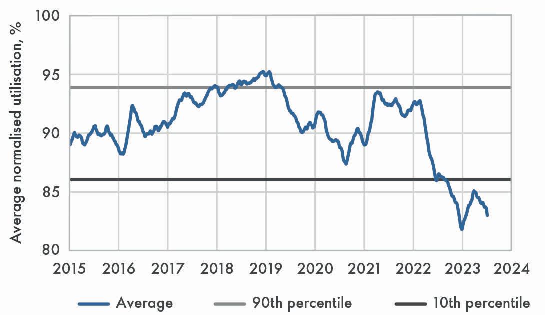
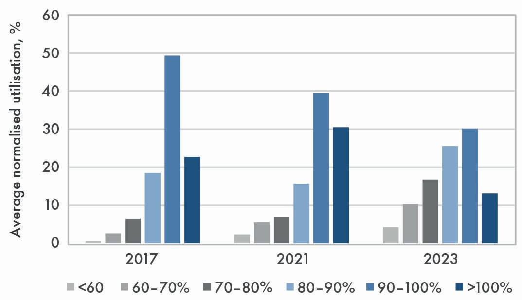
In response, EO plant operators are reducing their normalised work rates, or utilisation rates. An analysis of the normalised work rates of all Shell EO catalyst customers over the past eight years reveals that average utilisation has dropped from more than 95% in 2019 to less than 85% in 2023, as seen in Figure 1a. The distribution of work-rate ranges, seen in Figure 1b, indicates a significant shift to lower utilisation between 2017 and 2023. In 2017, less than 10% of customers were operating at utilisation rates below 80% (the sum of the three grey bars), shifting to more than 30% of customers by 2023. At the end of 2023, the average normalised work rate was well below that seen during the COVID-19 pandemic.
June 2024 14 HYDROCARBON ENGINEERING

June 2024 15 HYDROCARBON ENGINEERING
The challenges posed by low turndown
Low work rates, also known as low turndown, can present operational challenges. In recent decades, many plants have seen an upward capacity creep – the result of various debottlenecking schemes. However, operators forced to reverse this trend can encounter plant hardware constraints in attempting to achieve low turndown. This is a consequence of running at lower temperatures, which improves catalyst life and selectivity but creates lower steam pressure and a set of suboptimal operating conditions.
Fortunately, strategies and solutions exist, and some plants have been able to run under low turndown conditions by consulting closely with Shell Catalysts & Technologies. In part one of this two-part article, short-term solutions will be considered, with examples of tried and tested startegies. Part two of this article will characterise medium and long-term solutions. It is important to note that, while Shell Catalysts & Technologies has assisted some customers in implementing various operational modes to manage low product demand, the effectiveness and outcomes of these solutions may vary depending on specific circumstances and operational contexts.
Short-term solutions
All plants have a design work rate, which is by definition a utilisation of 100%. Depending on the design, it is possible to exceed this by setting more ambitious target
work rates, increasing the utilisation by 10 - 25%. Similarly, there is scope for running at lower work rates of 70 - 80%, which represents turndown operation. What happens when utilisation rates are below 70% or, even lower, at less than 60% – a situation defined as low turndown?
Shell Catalysts & Technologies has assisted some of its customers to implement three different modes of operation to cope with managing low product demand. Considered as short-term solutions, each mode has its own operational challenges and benefits.
Case study 1: operating at extremely low work rate
This case study involves a unit designed for a work rate of 145 kg/m³/hr (100% utilisation). The first catalyst charge was run at 125% of design and the second, owing to pandemic and market conditions, was restricted to 90% of design. The third charge is now running at less than 60% of design work rate because of ongoing poor market conditions.
The challenges faced by running at such a low work rate included catalyst operating constraints and plant hardware limitations, associated with low heat generation. In this case, modifications were made to pressure control valves on the coolant steam drum and reactor outlet gas cooler. These modifications removed the plant limitation and enabled operation using lower-pressure steam. The low catalyst temperature resulted in a sluggish chloride response and, additionally, a potential water impact to the catalyst under extremely low inlet carbon dioxide (CO2) levels was identified. To resolve these issues, the inlet oxygen content was reduced significantly and close attention was paid to chloride optimisation.
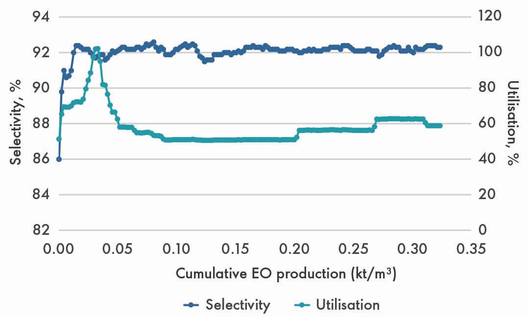
Following the catalyst optimisation procedure, operators reported being able to run at less than 60% of design work rate (less than 85 kg/m³/hr), and with excellent selectivity of approximately 92.3% (Figure 2). Furthermore, the catalyst lifetime should be greatly extended under these mild operating conditions.
Case study 2: start/stop operation
The second case study focuses on the operation of a single reactor with a capacity of 140 000 tpy of ethylene oxide equivalent (EOE). The main products include HPEO, MEG and EO derivatives. The operator was experienced in the use of high-selectivity catalysts, having operated with five charges of a latest-generation product. The average work rate of charges 1 to 3 was 270 kg/m³/hr. The current charge started up in 2022.
June 2024 HYDROCARBON ENGINEERING 16
Figure 1. Average normalised work rate (a) and distribution of work rates (b) for Shell EO catalyst customers.
a) b)
Figure 2. Stable operation and enhanced selectivity of the catalyst at reduced work rate.

Specialty Chemical Solutions
SUPERIOR PROCESS AND WATER TREATMENT SOLUTIONS DRIVEN BY SERVICE EXCELLENCE
Improving reliability, increasing throughput, and enhancing the efficiency and flexibility of operating units is important to you. Halliburton Multi-Chem offers a broad selection of chemistries, equipment, services, and automation to ensure successful results.
Through onsite technical service and engineering support, Multi-Chem collaborates with you to deliver solutions to your challenges. We’re here to help you.
halliburton.com/specialty-chemicals
© 2024 Halliburton. All Rights Reserved.
Product demand dropped during the operation of the fourth charge, when the average work rate was 200 kg/m³/hr. When faced with a work rate below 150 kg/m³/hr, less than 56% of charges 1 - 3, operations were constrained by the coolant pressure valve, low temperatures and inefficiencies. Clearly, an alternative mode of operation was required.
A new strategy was developed, driven by EO product storage constraints and typically involving one to three weeks of operation followed by a shutdown of one week in duration, when the reactor bed was under a nitrogen
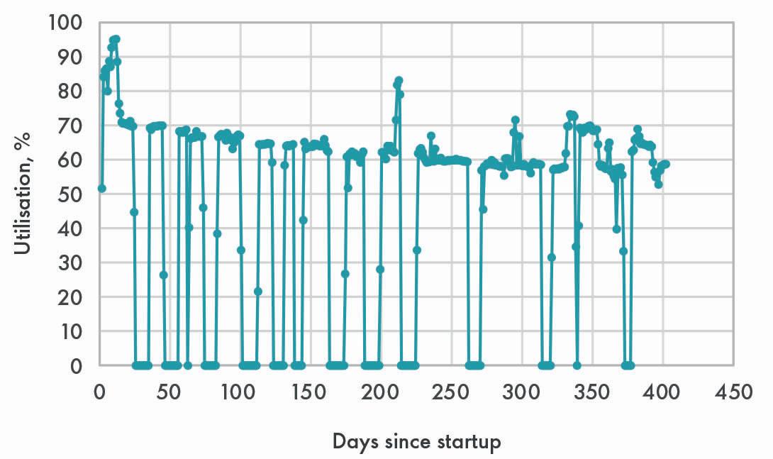
purge. On depletion of the storage level, and when there was sufficient demand, the unit was restarted. Although transient operation comes with inherent challenges, such as potential equipment damage caused by thermal stresses, liquid backflow and the challenge of chloride optimisation, the plant has been successfully operating in this cyclic mode since mid-2022. The strategy has the benefit of providing opportunities to execute routine and preventive maintenance activities during stop periods, if needed. The cyclic work rate is shown in Figure 3.
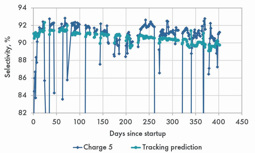
The operator’s deep experience with the catalyst enabled them to successfully achieve manageable work rates and stable operation. The potential difficulty in optimising chlorides during short uptime periods was overcome and energy savings were realised by eliminating utilities to the unit during stop periods. Despite the dynamic operating conditions, the catalyst performance has remained robust, with excellent selectivity, and exceeded tracking predictions, as shown in Figure 4.
Case study 3: reducing the number of reactor trains
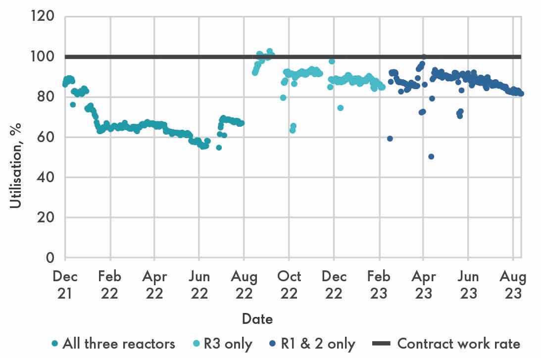
Many plants operate with multiple reactors that are run in a parallel configuration. The reactors may be identical, or of different sizes, which is the case at the plant in this case study. A three-reactor system is found comprising small, medium and large reactors in parallel with a design work rate of 250 kg/m³/hr. The company is currently running its sixth charge of high-selectivity catalyst, which was started up in 2021.
In 2021, due to declining market conditions, the operators attempted to run at a lower work rate of 160 kg/m³/hr, or 64% of design work rate. After operating this way for nine months, the company then adopted a novel operating strategy. This entailed running the large reactor (R3) first, while the other two were blocked off, and then switching to the operation of R1 and R2 while R3 was shut down. The combined catalyst volume in R1 and R2 equalled the volume of catalyst in R3, so this mode of operation entailed running only half the reactor catalyst capacity at any one time.
In this way, work rates of 220 - 228 kg/m³/hr (88 - 91% of design work rate) were achieved, equivalent to a 45% turndown of plant capacity.
By isolating individual reactors in a multitrain configuration and protecting the reactor beds with inert gas blanketing, flexible operation was achieved. The benefit of this strategy is the ability to operate the reduced reactor trains at near normal work rate, promoting stability and good catalyst performance. This blocked-out mode of operation also provides the ability to perform changeout of catalyst in an isolated reactor train while the other is still running. Additionally, the operator reported energy savings of 400 - 2000 kWh at its plant when running with reduced reactor trains. The work rates for the various reactor combinations are shown in Figure 5.
In the second part of this article, which will appear in the September issue of Hydrocarbon Engineering, the medium and long-term solutions for EO producers facing low work rate conditions will be discussed.
June 2024 HYDROCARBON ENGINEERING 18
Figure 3. The cyclic work rate of start/stop operation (100% = 270 kg/m3/hr).
Figure 4. Selectivity of the catalyst charge during stop/start operation.
Figure 5. Work rates for different reactor combinations at the plant.
The rapid progress in development of technology for the recycling of waste plastics is driven by two main factors. First, the introduction of recycled content can partially replace fossil feedstocks as a raw material for producing plastics, thereby reducing the carbon footprint of this invaluable material. Second, the effective recycling of waste plastics results in valorisation of this waste stream, providing a powerful additional incentive for reducing the environmental problem of waste plastics. These drivers have stimulated pledges from producers to increase the recycled content of plastics and legislators to introduce subsidies and mandates for the recycling of waste plastics. For example, the recent revision of the EU Packaging and Packaging Waste directive stipulates the reuse, recycling and other forms of recovering of packaging waste (instead of its final disposal) including specific targets for the recycling rate of plastic packaging.
A sound strategy for decreasing waste plastics begins with avoiding the use of plastics where better alternatives exist and reusing plastic items as often as possible. When end-of-life is reached, or when reuse is not an option (e.g. for reasons of hygiene), recycling provides a better alternative than landfill or incineration. For pure plastics streams of a homogeneous composition, mechanical recycling or chemical solvolysis provides an efficient low-energy route to recycling. However, for mixed plastics streams, these routes are not an option, and significant energy input is required to break the carbon-carbon bonds present in the polymers. Via pyrolysis or hydrothermal liquefaction, a mixed waste plastics stream can be converted into a waste plastics oil (WPO) which can serve as a raw material for the production of new plastics or chemicals. This article will explain

Jaap Bergwerff, Ketjen, explains why the hydroprocessing of waste plastic oils is an essential technology in the chemical recycling of waste plastics.
June 2024 19 HYDROCARBON ENGINEERING
why hydroprocessing is an essential technology for this type of chemical recycling of waste plastics.
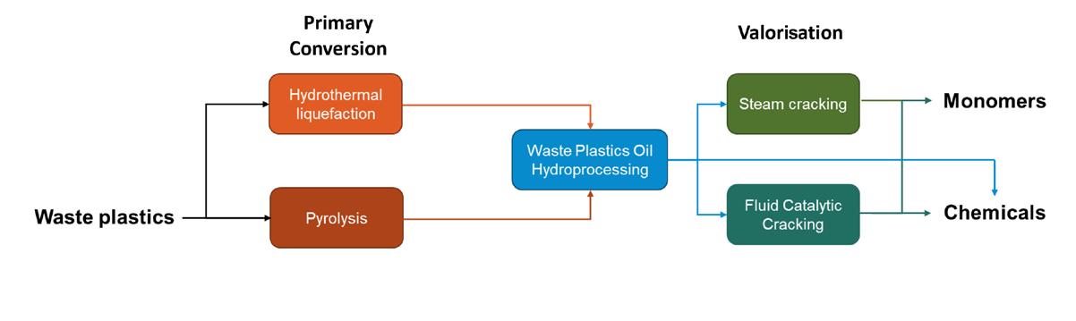
Different routes exist for the valorisation of the circular carbon that is contained in WPOs, as illustrated in Figure 1. Depending on the available assets or economic circumstances, monomers or chemicals can either be produced by processing of a purified WPO in a fluid catalytic cracking (FCC) unit or a steam cracker. Regardless of the route taken, hydroprocessing of the WPO is likely required. While the FCC catalyst can handle a certain concentration of contaminants, for introduction in a steam cracker, stringent specifications must be met. Moreover, a feed with a lower boiling point will result in higher yields of valuable monomers. This article will describe how hydroprocessing can be applied to upgrade WPO to a suitable feedstock.
Waste plastics oil composition
Before an effective hydroprocessing strategy can be developed, it is critical to understand the composition of the feedstock. A molecular fingerprint of the organic matrix can be obtained via multi-dimensional chromatography techniques combined with selective detectors for speciation. A quick comparison of the speciation of the N-compounds present in a typical WPO and in a fossil oil fraction, as shown in Figure 2, reveals that the type of N-compounds present in both oils is completely different.
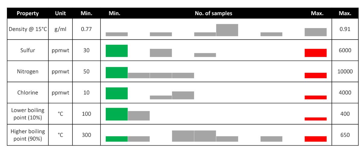
The composition of WPOs can vary greatly depending on the source of waste plastics and conversion technology used. The nature of the polymers in the mix, but also the presence of curatives, paints and other additives added to the plastics, and even non-plastics, present in the mix will affect the oil composition. Figure 3 illustrates the large variation in composition and physical properties encountered. Depending on how value chains develop, it is possible that the production of WPOs is carried out on a relatively small scale close to the waste collection location, while hydroprocessing of aggregated WPOs is carried out at a larger scale at a location linked to its valorisation. In any case, before developing a suitable strategy for the hydroprocessing of WPOs, understanding the composition of the feedstock and its fluctuation to be treated is critical. Finally, just as the composition of WPO depends on the plastics sources, it is bound to vary over time. The catalyst system will need to be sufficiently robust to deal with fluctuations in impurities concentration and reactivity and with changes over time.
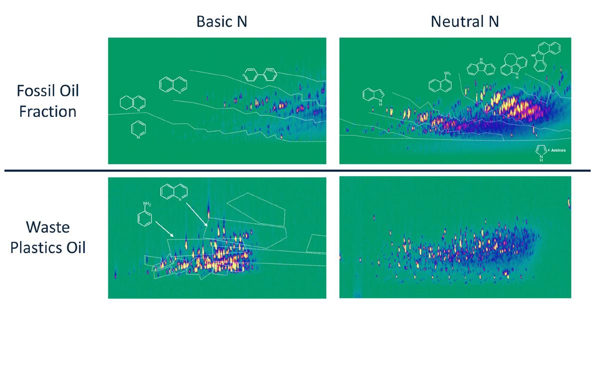
Figure 2. GCxGC-NCD plots showing the speciation of neutral (left) and basic (right) N-compounds in a fossil oil fraction (top) and a WPO (bottom). In these graphs, the location of a compound reflects its boiling point (x-axis) and polarity (y-axis).
Depending on the waste plastic source and conversion technology applied, the WPO can be more paraffinic or can contain a higher concentration of aromatics. The presence of highly reactive di-olefins originating from thermal cracking reactions can make crude waste plastic oils very difficult to handle and sometimes even unstable under storage.
The presence of heteroatoms in WPOs can originate from many different sources. In Table 1, the different elements, their origin and the nature of the molecules present in the WPO are listed. Oxygen in WPOs can be present in many different forms and originate from many different sources. In general, the hydrodeoxygenation (HDO) reaction of most of these compounds will be relatively rapid, but species like phenols can require more severe conditions and/or a dedicated catalyst solution.
A closer look at Figure 2 shows that, in fossil oil fractions, N is mostly contained in aromatic rings and significant hydrogenation is required to liberate N from these compounds. On the other hand, the N-compounds that are generally present in waste plastic oils, such as primary amines, are generally less refractory and therefore relatively easier to decompose. In the
June 2024 HYDROCARBON ENGINEERING 20
Figure 1. Different pathways for the chemical recycling of waste plastics for the production of new plastics or chemicals, highlighting the role of WPO hydroprocessing.
Figure 3. Range of properties and composition as found in a collection of WPOs, illustrating the extreme variation amongst different WPOs.
two-dimensional gas chromatography (GCxGC) plots, this is expressed as a lower boiling point (more to the left) and a lower polarity (more towards the bottom of the plot). Nevertheless, the very high concentrations present in the WPOs still require sufficient hydroenitrogenation (HDN) activity of the catalyst system.
Whereas in hydroprocessing of fossil fuels, the near complete removal of highly refractory S-compounds, such as substituted dibenzothiophenes, is a real challenge, the S-species present in WPOs are generally more reactive.
Dealing with the presence of halides is a specific issue in the hydroprocessing of WPOs. Originating from PVC or flame retardants, the organic halides will rapidly decompose over typical hydroprocessing catalysts to form HCl or HBr. Obviously, the presence of these compounds can create corrosion issues and puts specific demands on materials used in the process. Moreover, when combining with the NH3 liberated in the HDN reaction, precipitation of NH4Cl or NH4Br in colder parts downstream of the main reactor can cause significant operational issues in lab-scale and commercial reactors.
Silicon (Si) and phosphorus (P) are contaminants common in WPOs but are also found in fossil oil fractions, waste and residue oils and bio-oils. As in these applications, dedicated guard bed catalysts can be applied to decompose Si- and P-containing compounds and capture the element and their inorganic salts on the catalyst.
While present at low concentrations, it is still critical that a full account of all elements is made. Even at low concentrations, elements like arsenic or lead can have a significant impact on catalyst activity and their accumulative effect over a cycle can result in a severe impact on activity. Understanding the
Table 1. Origin and nature of different contaminants that can be present in WPOs
Element Origin in waste plastic streams Molecular presence in waste plastic oils
O PET, paper, organic contaminants Large range of different compounds
S Polysulfides
Rubbers, plasticisers
Thiols, thiophenes
N Polyamides (Primary) amines, pyridines, nitriles
Cl PVC
Br Polybrominated hydrocarbons
Flame retardants
Si Silicones
Organic chlorides
Organic bromides
Sealants, surfactants (Substituted) cyclic siloxanes
P Organophosphates
Corrosion inhibitors, flame-retardants
Arylphosphates, polyphosphates
Metals (Cd, Cr, Fe, Mo, Ni, Pb, Sb, Ti, Zn, and others)
Organo-metal compounds
As a reflection of the variety in origin of the plastic feed, a range of different metals can be detected in WPOs.
A range of fillers, plasticisers, catalysts, inks, pigments
x KETJEN Renewables POSTER_210mmx146mm.pdf 1 4/30/24 3:29 PM
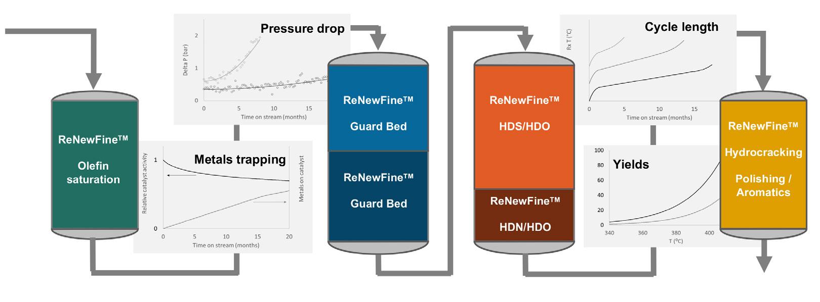
RENEWABLES
Catalysts matter! Our bespoke catalyst solutions are tailored to your needs no matter where you are in your energy transition journey, helping you achieve your sustainability goals and maximize profits.
As an independent catalyst producer, we have the expertise to help you succeed in operating your assets autonomously. Our ReNewFine portfolio works regardless of your process technology.


ReNewFine Portfolio for Renewable Diesel & SAF ReNewFCC Portfolio for FCC co-processing applications As an industry leader, we provide a comprehensive portfolio of catalyst solutions
more information, scan the QR code.
For
ReNewFine Portfolio for Waste Plastic Oils Hydrotreating
ADVANCING SUSTAINABLE SOLUTIONS
interaction of the different metals with the active catalysts is key to designing an effective catalyst system that is able to prevent catalyst poisoning, allowing these elements to exit the reactor via the product.
Hydroprocessing strategies
Before hydroprocessing is carried out, in designing a catalyst system for the upgrading of WPOs, the composition of the feedstock and product are both of critical importance. In general, the reactions that are taking place over the entire system are executed in order of reactivity of the reactants. In Figure 4, a catalyst system for WPO hydroprocessing is presented, where it should be noted that the exact process scheme and number of reactors can vary in practice. First, a low temperature hydrogenation step can be carried out to saturate the reactive di-olefins that are present in the feed. In this way, a severe exotherm on the main catalyst bed is prevented, resulting in potential uncontrolled polymerisation and catalyst deactivation. This step results in a stabilised WPO that can be further upgraded.
Subsequently, inorganic impurities, such as P and Si are removed by dedicated guard bed catalysts. Depending on the concentration of these impurities, one approach could be to use parallel guard bed reactors to allow for exchange of the catalyst while continuing the process. When designing the optimal guard catalysts, the aim is always to provide sufficient
activity to capture all contaminants in the guard bed layer, without causing deposition near the external surface of the catalyst particle, which results in deactivation. This means accessibility of guard bed catalysts is maximised, while reactivity needs to be tailored. Since the reactivity and molecular size of the impurity-containing molecules in WPO can be very different from other types of feedstocks, dedicated guard catalysts are required for this application.
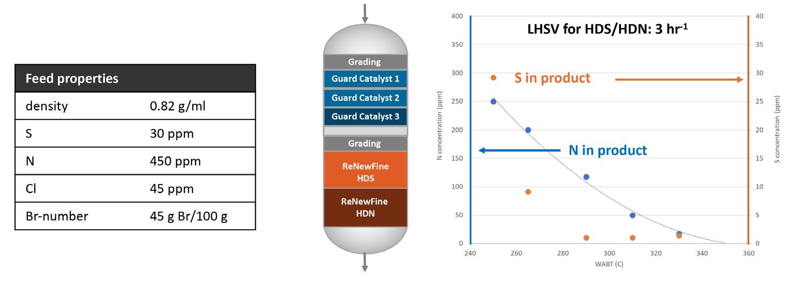
Based on decades of experience in the hydroprocessing of a range of feedstocks, a deep understanding of the effect of catalyst composition on hydrodesulfurisation (HDS), HDN and HDO activity has been obtained. Using this expertise, a complete ReNewFine catalyst portfolio was developed for the removal of these heteroatoms from WPOs. The result of this step is a purified pure hydrocarbon stream. Figure 5 shows the results of an experiment in which a WPO was processed over a series of ReNewFineTM catalysts to remove S and N. Complete HDS and HDN conversion was already obtained at a reasonably low temperature.
Finally, a post-treatment step may be required to alter the physical properties of the product. When the product is applied as steam cracker feed, hydrocracking may be used to achieve a lower average boiling point and optimise monomer yields. In the production of waxes or oils from certain paraffinic WPOs, isomerisation can help to improve the properties of the product, while deep hydrogenation may be required to produce certain chemicals.
Conclusion
Hydroprocessing is a critical step in the valorisation of WPOs to produce new chemicals and plastics, regardless of the feedstock used or the desired product. In addition to the process lay-out and reaction conditions, a detailed understanding of the composition of these feedstocks is the basis for designing catalyst solutions for WPO hydroprocessing. Once a molecular fingerprint of the WPO has been obtained, using a range of dedicated catalysts and an application model that contains the catalyst activity profile, the optimal ReNewSTAXTM catalyst loading can be designed.
June 2024 HYDROCARBON ENGINEERING 22
Figure 4. Schematic representation of a process for the hydroprocessing of WPO, illustrating the different steps that are required, and some critical parameters to follow and model.
Figure 5. Results of a hydroprocessing test with a WPO, showing the removal of S and N as a function of T.
Taco
van der Maten, Malvern Panalytical, the Netherlands, discusses the use of X-ray diffraction (XRD) as a valuable tool for catalyst characterisation.
When it comes to the catalytic cracking of hydrocarbons, the name says it all: catalysts – often zeolites, in modern refineries – have proved to be a game-changer in helping the industry produce higher volumes of higher-value petroleum products. As catalysts become more efficient, so too do the economics, land use, and resource consumption of refineries. Furthermore, by enabling the shift away from more energy-intensive thermal cracking, catalysis plays a central role in reducing the environmental footprint of the hydrocarbon value chain.
Catalysts are used in the petrochemical industry for accelerating chemical processes of all kinds. Different catalysts are used for different purposes, so there is no one catalyst that rules all. For example, a catalyst that excels in oxidation reactions may not be as effective as another catalyst in the amination process. These varying properties make it more challenging to find efficient catalysts. More catalysts mean more possibilities, leading to increased sampling workloads and longer testing periods to find

catalysts with the optimal properties for a given process. In the petrochemical industry, these tests take up valuable time in a highly competitive market.
In everything from the cars we drive to the materials used in our homes and workplaces, and even the production of solar energy, catalysts are hard at work behind the scenes.
The need for speed in catalyst development
What is more, demand for catalysts is growing, with market projections forecasting a compound annual growth rate of at least 4% for the next decade. This is partly driven by the expected increase in demand for the polymers, chemicals, and petrochemicals to support the world’s growing population. At the same time, the environmental crisis is spurring the continuous development of new processes and technologies that are based on waste materials and benefit from the influence of catalysis – including carbon capture and utilisation (CCU) and the conversion of waste household plastics into new feedstocks
June 2024 23 HYDROCARBON ENGINEERING
or biofuels. If we are to realise such innovations at the scale required for a successful sustainability transition, meeting the additional demand for catalysts will be crucial.
More specifically, fulfilling this demand will require not only more catalytic materials, but better ones. And just like the outputs they enable, the catalysts themselves will need to be more cost efficient and more sustainable to produce.
In turn, whether the analysis of the material is taking place in an R&D lab or as part of a refinery’s quality-control procedures, reliable and in-depth characterisation of catalysts is fundamental. Only then is it possible to understand the precise properties of a sample, what those properties mean for the reactants, and how to optimise these properties to ensure the right balance between performance and efficiency.
From area to zeta
It is important to remember that catalyst characterisation is key to more than just designing and developing new catalysts that perform well under the intended conditions of use. After all, thorough analysis is also essential for designing and developing petrochemical processes and platforms that perform in agreement with the catalysts, at the intended scale.
With this in mind, researchers and refineries looking for a comprehensive understanding of a given catalyst should ensure their assessment includes physical, structural, and elemental analysis. Within these categories, several properties can affect the outcome of a catalytic process, including particle size and shape, surface area, crystalline structure, porosity, and zeta potential. In general, zeolites used in hydrocarbon cracking increase the rate of reaction as a result of the surface binding and pore-intrusion to the reactants. Achieving the optimal catalyst structure and surface chemistry for the process in question is therefore a priority.
Advanced characterisation with the X factor
In the petrochemical field, X-ray diffraction (XRD) is an extremely valuable tool for catalyst characterisation. It is based on the premise that, by using an X-ray source and detector to measure a sample’s scattering angle at a fixed wavelength and by applying Bragg’s law, users can determine the space between the
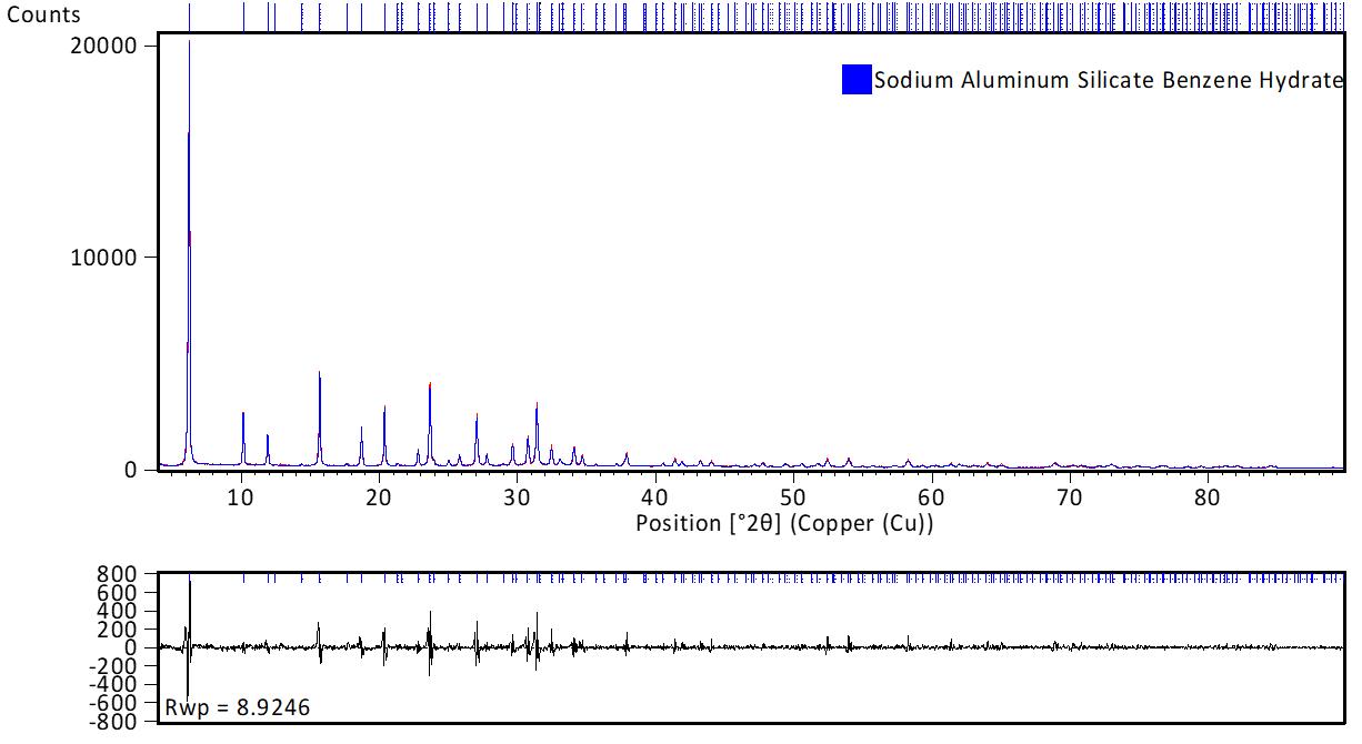
Figure 1. Example of an X-ray diffractogram of a zeolite interacting with benzene hydrate – upper graph –demonstrated by a good fit between the predicted and measured data, as indicated by the low fitting residuals –lower graph.
scattering planes of a material. In turn, this enables phase identification and quantitative analysis of the sample under investigation. Recognised in industry for years as an invaluable tool, several international test methods have been developed. Listed below are several of the most used test methods.
ASTM test methods1
n D5758 - Standard Test Method for Determination of Relative Crystallinity of Zeolite ZSM-5 by X-Ray Diffraction.
n D4926 - Standard Test Method for Gamma Alumina Content in Catalysts and Catalyst Carriers Containing Silica and Alumina by X-ray Powder Diffraction.
n D8352 - Standard Test Method for Determination of Relative Crystallinity of Zeolite Beta by X-Ray Diffraction.
n D5357-19 Standard Test Method for Determination of Relative Crystallinity of Zeolite Sodium A by X-ray Diffraction.
Regarding hydrocarbon processing in particular, this technique provides information on the bulk structure and composition of solid catalytic materials, such as the zeolites and metal oxides used in catalytic cracking. Therefore, XRD is often used in hydrocarbon catalysis research to determine crystalline structure and size, as well as unit cell size. Crystalline/amorphous rations are used in quality control. On top of this, when analysed using an XRD instrument with non-ambient chambers, catalysts can be examined under a variety of conditions (such as pressure, temperature, and humidity), thereby unlocking insights into reaction pathways and intermediate phases. Users can also monitor processes that influence the activation of a catalyst, such as oxidation or reduction reactions.
Better yet, not only is the underlying theory sound, but XRD brings all kinds of in-use benefits for scientists – those in the lab as well as in industrial settings. Requiring minimal sample preparation and relatively little time for an analysis (often under 20 minutes), XRD is a fast and convenient technique that is popular in industrial environments. Non-destructive, versatile, and highly accurate, these tools enable users to gain valuable insights into a catalytic material, and thereafter make informed decisions about optimising its performance in refinery processes.
Complementary techniques for a comprehensive understanding
In any characterisation activity, it is important to examine a hydrocarbon processing catalyst from as many perspectives as possible in order to paint a full picture of its properties. Indeed, XRD is an important technique that can provide important insights into catalyst samples. X-ray fluorescence (XRF) technology, for instance, can be used to support elemental analysis of the catalytic material. Highly precise and reproducible, this spectroscopic method can help determine the Si/Al ratio of a zeolite, for example, or even the presence of so-called catalyst poisons, thereby helping prevent chemical deactivation.
Meanwhile, small-angle X-ray scattering (SAXS) measures the scattering that results from fluctuations in electron density at the nanometer scale, making it an extremely useful technique for many catalysts and a good complement to XRD. With SAXS, users can determine particle and pore size, volume-weighted size distribution, and the specific
June 2024 HYDROCARBON ENGINEERING 24
surface area of crystallites. Alongside this, investigation of short-range atomic order via pair distribution function (PDF) analysis enables a better understanding of nano- and non-crystalline materials and amorphous phases. In this way, SAXS can complement Brunauer-Emmett-Teller (BET) and Barrett-Joyner-Halenda (BHJ) pore size and volume analysis test.
For refineries and labs seeking a fully cutting-edge characterisation approach, it is time to take advantage of the growing availability of automated analysis instruments and intuitive, custom-built analytical software. These are both areas that have made significant advancements in recent years and are now supporting faster, simpler, data-driven analysis in the lab and at the production line, thereby helping to improve catalytic processes – and related margins and efficiencies – still further.
Catalysing a more sustainable petrochemical industry
The petrochemical landscape is changing fast, and that change must speed up further as the sustainability transition takes hold. More efficient catalysts – that enable more sustainable operations and applications alike – can help refinery operators to step on the pedal.
For that, of course, catalyst development itself needs to stay ahead of the pace. With accurate and reliable XRD, supported by other complementary methods, users are assured of robust and informative characterisation that will enable both catalytic materials and the reactions they accelerate to perform better and more efficiently.
XRD: the fast method for the future of petrochemicals
XRD is driving catalyst development in several ways. Solid growth and environmental pressures are encouraging research into better catalyst materials, so that the market can effectively serve the growing demand for polymers, chemicals, and petrochemicals.
In the search for better catalysts, innovative new materials can only be discovered if researchers understand the precise properties of their catalyst. This understanding, gained through in-depth XRD characterisation, sheds more light on how the reactants will behave and how best to optimise their reactions.
XRD characterisation is an excellent method for unlocking the secrets of a catalyst material. It is widely supported by several test methods and offers a variety of analytical advantages. XRD often provides analysis in less than 20 minutes, and it works on multiple samples while not destroying them in the analytical process.
XRD is a fast, convenient analytical method for innovators seeking to optimise their catalyst materials. Combined with other technologies such as XRF or SAXS, XRD is the foundation of a characterisation process that enables innovation in a rapidly changing petrochemical landscape.
Note
An extensive list of ASTM International Catalyst Standards can be found at https://www.astm.org/products-services/standards-andpublications/standards/catalyst-standards.html

June 2024 HYDROCARBON ENGINEERING 26
Bradford Cook, Sabin Metal Corp., USA, outlines best practice control points for refiners looking to maximise the value and lifecycle of precious metals catalysts.
The value of precious metals continues to rise both in terms of their pricing in the marketplace, and their critical, technical applications in plants. Precious metals are likely among the most reused substances on planet Earth as they are almost always retrieved and recycled regardless of the form they may take. Many petroleum and petrochemical processes use catalysts containing precious metals (PMs) – most commonly platinum, palladium, ruthenium, rhodium, gold and rhenium. When the time comes for these catalysts to be replaced (changed out during turnaround), the plant realises a level of restored efficacy to the process, increased speed of process reactions, etc. After the spent catalysts are sent to a precious metal refiner, a vast majority of catalyst owners focus only on the final returned value contained, and in so doing they miss opportunities to learn best practices and protect their

profits. This article seeks to provide readers with an overview of the various control points within the precious metal catalyst life cycle, and what knowledge can be gained to maximise financial returns while minimising difficulties.
Control point one: the purchase
Proper lifecycle management must include every step or action where the precious metal catalyst is handled and whenever calculations are made regarding the PMs contained. The first point that must be understood clearly is the amount of precious metal purchased within the fresh catalyst. If your company had some of this material sampled and tested, well done. The variability of precious metals loading when the catalyst was manufactured means that each catalyst bead is slightly different, so it stands to reason that each drum of the catalyst is also
June 2024 27 HYDROCARBON ENGINEERING
slightly different. Manufactures of products containing precious metals try very hard to keep the level of that ingredient to the minimum, agreed-upon amount. Consider the law of averages: half of the drums of catalyst produced will contain less than the average amount of precious metal, and half will contain more than the average. If a catalyst manufacturer makes reformer catalyst in batches of millions of kilos, how will you know which drums you received? The second key issue is the amount of water the catalyst contains at purchase. The average water content should be listed on the certificate when the catalyst was purchased and will factor in when evaluating the spent catalyst PM value when the reactor is ultimately changed out. Knowing how many ounces of precious metals you have is only possible with thorough record-keeping ‘from the cradle to the grave’ of the catalyst life cycle.
Control point two: in-situ considerations
Excuse my dust
Throughout this catalyst life cycle, dusts are being formed (also known as ‘fines’ in the industry). The catalyst beads rub together during the vibration of road transport, so the first consideration comes when the fresh catalyst is being loaded into the reactor. Reactors should never be loaded (or unloaded) in a high wind. Many catalysts – particularly alumina-based catalysts – are impregnated with PMs on their exterior surface to enhance their efficacy, so fines can contain two to ten times more PM per kg than the original catalyst bead. For example: typical precious metal catalysts are loaded at 0.25% platinum, so losing 1 kg of fresh catalyst beads is like losing 2.5 g of platinum, which is about €70.00 at today’s prices. Losing 1 kg of dust during the catalyst’s life cycle can be the equivalent of 20 g of platinum or greater, which is €500 of precious metals or even more.
Carbon negatives, et al
It is also important to remember that throughout the catalyst’s life cycle, many impurities accumulate in the

catalyst during processing: coke, carbon, and other elements if additives have been used to extend the catalyst’s life. All these factors have an effect concerning the final recovery at the precious metal refiner.
Another aspect worth mentioning is that once the spent catalysts reach the PM, refiner tests are carried out to determine the carbon and coke content, the moisture content, benzene levels, etc. This information is initially used to see if any thermal reduction is necessary to clean the catalysts of these impurities before proper sampling can take place. However, some savvy process engineers use this impurity information to obtain critical data on their previous run. For example, does the high carbon content in the spent catalyst from this reformer unit indicate that there was a channelling issue? Specific knowledge of reactor operation could be enhanced by examining the condition of the spent catalyst.
Control point three: the reclaim
The turnaround
Proper packaging and weighing and ultimately classifying the spent catalysts for international shipment can be a daunting task – especially for someone who does not handle such things regularly. Many petroleum and petrochemical firms outsource the changeout completely, but a watchful eye is still needed from the ‘inside’ to ensure that all precious metal-containing materials have been fully collected, that the cargo is fully secure, and that hazardous classification has been completed correctly. At the end of the day, losses and liability will hit the operator’s bottom line – not the contractor’s.
Transport and logistics
Taking responsibility for the shipping of hundreds of tons of spent catalysts containing millions of Euros worth of platinum, palladium, or other valuable metals is best left to experts. Sabin International Logistics Corp. (SILC) is responsible for arranging the transportation of customers’ spent process catalysts from virtually any point on Earth to Sabin’s recovery and refining processing facilities. When shipping spent precious metal-bearing catalysts, operators must comply with a labyrinth of domestic and international rules, regulations, permits, and many other roadblocks. As with many other complexities in the arena of international trade, a specialist is often required to help sort this out.
Choosing a PM refiner
First and foremost, without an honest precious metals refiner, one cannot hope to receive any quality of service. The topic of ethical compliance (or non-compliance) in the precious metals industry might someday be the next Netflix documentary, but until then, the only way that catalyst owners can protect their financial interests and avoid all legal complications is to exercise a high level of diligence while selecting their PM recycler. Ridiculously low terms can be given by the company that distorts the PMs content by the tiniest fraction of a percent. Sadly, the precious metals industry has seen more than its fair share
June 2024 HYDROCARBON ENGINEERING 28
Figure 1. Electric arc furnace in operation.


Delivering future-focused intelligent flow control With the latest actuation technology from Rotork, you can improve efficiency, reduce emissions, minimise your environmental impact and ensure safety. Our products are supported by an effective and comprehensive site services programme, proven to increase uptime and reduce your maintenance costs. Contact us to find out more or speak to one of our expert advisors. +44 (0)1225 733200 | mail@rotork.com | rotork.com
of scandals, criminal proceedings and convictions for smuggling, illegal dumping of hazardous materials and outright fraud. The precious metals assets in the possession of a company suddenly facing criminal charges or filing bankruptcy can be tied up in the courts for many months or even years.
Regulatory and legal entities, as well as both industry and traditional media, should be consulted to ensure a proper investigation. Requesting records and certifications for safety, environmental and other regulatory adherence is imperative. Lastly, it is always highly recommended that the customer audit the precious metals refiner site to observe first-hand the facilities, records and practices.
After ethical practice, the second most important consideration in this equation is the proper weighing of the catalyst shipment, accurate sampling, and the highest industry standard of PMs analysis. There is a substantial amount of false economy in adopting a ‘lowest bidder’ mentality regarding sampling and assaying. Quality, unfortunately, cannot and does not come cheaply.
Accurate precious metals asset evaluation requires trained people, time, calibrated equipment, and experience for it to be right.


Representation on site
Once the pre-qualification audit has been accomplished and it can be documented that the precious metals refiner has the tools, techniques, and trained personnel to successfully perform the scope of work, catalyst owners are highly encouraged to attend and witness the PM catalyst weighing and sampling process. If the client cannot be present, many high-level third-party representation companies specialise in this industry. These reps act as the eyes and ears on-site to eliminate the human error factor, provide valuable corroboration of the weights and conduct of the PM refiner, and maintain custody control of the samples drawn for final PMs analysis. In short, the data gathered is confirmed and it can be verified that all processing and sampling proceeded precisely as intended.
Control point four: record keeping
Trends in the industry have people moving into new jobs and/or areas of responsibility at an increased rate. Since the typical life expectancy of a PM catalyst is two to five years, more and more purchasing agents, procurement managers, and process engineers are seeing their first catalyst change out every year. This underscores why companies need a formal in-house programme for precious metals.
Spreadsheets and databases are vital to preserve the historical information from every PM changeout and recovery, as well as specialised knowledge that has been learned regarding vendors, their performance, etc.
Understanding contract details
Many companies are unaware of the more technical aspects of PM recovery contracts, as the terms and conditions tend to be somewhat unique.
Misunderstanding some contractual details can lead to major losses of revenue. It is important to remember that the expenses for transportation, PM refining services, and third-party representation are dwarfed by the inherent value of the precious metals. Overlooking or failing to take contractual details into account can cost more than the catalyst reclamation itself. Below are just some of the contractual details that can drastically decrease metal value returns and/or increase costs:
n The splitting limit: once the buyer and seller have their analytical results in hand, the splitting limit defines the maximum acceptable difference. If the two party’s assays are within the splitting limit, the average of the two is calculated and the money can change hands. If the two assays are further apart than the splitting limit, a control sample is sent to a third-party lab to act as an ‘umpire’ and settle the dispute. Standard industry practice on PM catalyst calls for a splitting limit of 1% relative, but less-than-scrupulous PM refiners would try and increase this to 5% or even 10% relative. This splitting limit manipulation forces the compromise of huge amounts of money. The 1% splitting limit not only minimises the amount of risk, but also helps to confirm the analytical accuracy as it compels the two labs to reproduce each other’s results.
June 2024 HYDROCARBON ENGINEERING 30
Figure 2. Spent catalyst.
Figure 2. Various pure precious metals.
n Limiting the lot size: this practice provides another level of control and risk management. It is in no one’s best interest to have too much monetary value within any one assay lot because standard deviation and repeatability must always be taken into account. Laboratory accuracy does not increase simply because more money is at stake. It should be ensured that elected PM refiners create many smaller-value (e.g. US$500 000) assay lots, rather than a lesser number of larger-value lots.
n Penalties and hidden charges: some PM reclaimers apply penalties within the ‘fine print’ of their contracts for the levels of powder contained, the carbon content, or even minuscule levels of certain other elements in spent catalyst shipments. These penalty charges can exceed US$40 000 per instance if the client is not well educated in such hidden risks.
The most important control points for profit protection can be synthesised down as follows:
n Contract details: the unique terminology used in PM reclaim contracts should be understood and fine print should be read carefully.
n Third-party witnessing: a witness should be hired for the reclaim and operators should consider having the catalyst manufacturing process and the loading/unloading of reactors repped.
n Third-party lab: operators should understand the exchange of assays and keep detailed records. This allows operators to know if the third-party lab is doing a good job. A rule of thumb for exchanges is that only approximately 10% should go to umpire, and the law of averages says that operators should win approximately 50% of the time. If third-party assays are resulting in higher percentages than that, operators should consider looking into other labs.
n Shipping and hazardous classification: outsourced catalyst handlers can help greatly but it is important that the experts (internal and external) ensure that the operator’s liabilities are covered, and that the expenses are reasonable. Hazardous goods transport can be far more expensive than non-hazardous, so good care should be taken in correctly classifying your materials for shipment.
n Spent catalyst condition: ensure condition reports are passed through the engineering group as there may be valuable information on process improvement, equipment health, etc.
n Precious metal refiner selection: due diligence is the key. This means full compliance with all regulatory, safety, and environmental records, financial reviews, certifications, and a hands-on audit to see documentation and capabilities first-hand.
n Record keeping: maintain detailed spreadsheets for every PM catalyst unit – from the purchase through the changeout and reclaim. This will enable catalyst use to be tracked carefully over the years. Historical recovery for each unit and vendor performance can be evaluated and, most importantly, operators will know exactly where every ounce of PM resides at all times.
Conclusion
Operators should make sure that PMs end up with a responsible recycler and root out and eliminate unethical and wasteful practice. In the PMs industry, it is vital to know what information truly matters.
Understanding what the true financial priorities are, educating employees and establishing internal best practices for PM catalyst life cycle management is key. Knowing the details on how materials will be sampled and treated and having them verified is also very important and, most of all, knowing exactly with whom one is dealing.

Think. Create. Change.
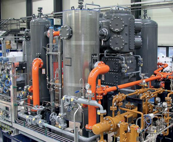


On Demand Webinars Explore our library of free-to-access On Demand Webinars, covering a range of topics in the downstream sector Visit: www.hydrocarbonengineering.com/webinars
Virginie Bellière-Baca, Sulzer Chemtech, discusses customer partnership, innovation, and the endless evolution of technology in the downstream industry.

Innovation excellence does not exist in a vacuum. Today’s world is globalised, connected, and fast evolving. Across industries, customers have access to an increasing spectrum of product offering. To stay competitive, it is important to look beyond existing borders and deeply understand the whole value chain where customers play, and thereby identify the real challenges they face. Maintaining innovation leadership
demands agility to solve these challenges in the most comprehensive way. The latter is not possible from a single, isolated product mindset. Acting quickly in the development of effective solutions is only possible through an open innovation approach. Far from regarding the boundaries of core know-how as limitations, understanding these boundaries is how companies keep agility through focus, while being flexible
June 2024 33 HYDROCARBON ENGINEERING
enough to develop the necessary partnerships to innovate with holistic and integrative solutions. Ultimately, collaboration is the essence to create the biggest value for customers.
Placing customers at the heart of innovation
The cornerstone of such an approach is cultivating strong, collaborative relationships with customers, aimed at creating a clear picture of their unique needs. After all, nobody knows as much about the challenges that customers are facing as they do themselves.
Feedback plays a critical role in this process, facilitating a continuous cycle of improvement and adaptation. While dedicated market research is important to excel in innovation, it only generates effective value when assessed from the customer angle. In that sense, customer insights are essential in validating and analysing market trends. A thorough understanding of the customer needs is key to be able to differentiate game-changing market trends from weak market signals. Ultimately, fostering exchange and collaboration with customers is critical to accurately anticipate future challenges, enabling the elaboration of customer-centric, value-generating and long-term R&D roadmaps. As well as learning more about customers directly, it is also important to encourage knowledge sharing within the community by supporting technical seminars, international conferences, and other forums. While it is true that not every idea, connection, or development made through these events will benefit a business directly, there is still value in helping the broader community grow its knowledge and encourage innovation.
On a more practical side, another key element of placing customers at the heart of innovation is ensuring they have access to the facilities they need to test their products and processes. After all, while large companies are usually well equipped with their own testing facilities, many businesses lack the equipment and expertise needed to run pilot-scale tests.
For this reason, it is vital that companies truly committed to customer-centric innovation provide those customers with access to pilot testing services. Ideally, they operate several test centres around the globe, offering a comprehensive number of separation and polymer reaction units, highly skilled test engineers, and analytical equipment to support local markets. This testing can help validate the assumptions made in process design and support customers with their development projects.
Practical innovation
Innovation is fundamental to creating and delivering solutions that offer real benefits. A focus on practical innovation means that the true value of a breakthrough lies not just in its novelty, but in its ability to solve specific tasks while enhancing efficiency and sustainability in day-to-day operations.
The challenge, however, is to balance these innovative solutions with the practicalities of existing systems. For innovation to be truly impactful, it must not only be groundbreaking but also achievable within the existing infrastructure. This requires innovations to be adaptable, scalable, and able to integrate seamlessly, ensuring they can
deliver immediate benefits without necessitating extensive overhauls.
For instance, consider the polymer industry’s drive to replace traditional plastics with more sustainable alternatives. The viability of such materials often hinges on their compatibility with existing manufacturing processes and their performance in real applications. As such, it is no surprise that bioplastics like polylactic acid (PLA), which can effectively replace conventional plastics in applications such as disposable cutlery, are growing in demand at a much higher rate than other bioplastics.1 By ensuring that these new materials can be easily adopted and offer comparable – if not superior – performance, innovators can significantly increase their chances of widespread acceptance.
In essence, practical innovation bridges the gap between the potential of new technologies and the realities of their application. Balancing groundbreaking ideas with their feasibility ensures that innovations both push the boundaries of what is possible and meet the immediate needs of the market, driving forward sustainability as well as operational efficiency.
Collaborative innovation
Open innovation, characterised by collaboration and partnership between companies and/or public institutions, is of increasing relevance today as more companies venture into new green applications such as renewable solutions, carbon capture and utilisation, and polymer recycling technologies. Open innovation allows the best utilisation of expertise and resources, enabling the development of high value-added innovation to be brought to the market for timely and positive impact for green transition.
Every successful technology starts from the need for a certain challenge to be solved, which triggers experts and innovation teams to come up with ideas. The process involved in transforming these sparks of inspiration into a market-ready solution involves a number of complex steps and is multifaceted.
In the ideation stage, initial concepts are evaluated for their technical feasibility and potential impact for further refinement for alignment with real-world needs. In the next development stage, concepts begin to take shape, with designs or processes being tested and validated to ensure they meet the developmental goals.
Already in this initial stage, it is of utmost importance to discern if it makes sense to undertake the development fully in-house, or to open to potential alliances with customers and/or strategic technology partners in a joint development approach. The selection of the right technology partner is crucial for effective and successful development. Not only should the ideal partner have the skilled expertise, infrastructure, and capability to support the development work, the partner should also share the same high regard for respecting intellectual property rights and have a proven track record in developing innovative solutions for customers. Successful collaborative innovations have led to the development of heat transfer and separation technologies in the conversion of plastic waste to valuable chemicals such as polystyrene waste to styrene, and skid-mounted separation technologies in the processing of bio-ethanol from carbon-rich
June 2024 HYDROCARBON ENGINEERING 34
RELIABLE CONSISTENT RESULTS

Proven, advanced formulations ideal for your processes, industry, and applications. More and better choices in heat transfer fluids based on our over 35 years experience.
www.paratherm.com 2009 Renaissance Blvd., King of Prussia, PA 19046 USA Int’l: +1 610-941-4900 Fax: +1 610-941-9191
gas emissions in steel production, supporting decarbonisation strategies in hard-to-abate industries.
Furthermore, technical validation is an essential step to prove initial concepts as well as to prepare for scale-up, prior to launch and implementation. R&D centres and pilot testing infrastructure play a vital role in this phase and need to offer human expertise along the necessary equipment for refining and testing new technologies. Customer involvement is essential in this phase, as the way to fine-tune developments to really meet specific needs. In this way, testing centres become innovation hubs, where researchers and engineers work together with customers to develop solutions that tackle complex challenges, from improving mass transfer processes to enhancing sustainability in chemical processing.
Through collaboration with R&D centres with the capability to perform feasibility studies, testing, process scale-up, process development, production of samples, as well as technical sales support and analytical services, companies can bring validated technologies to market that advance the state-of-the art and meet the pressing needs of industries and societies. To drive customer-centric product and process development through continual customer partnership, Sulzer has expanded its testing facilities with its new innovation hub, InTecH Singapore (see Figure 1).
Iterative innovation
One of the vital things to remember about innovation is that it is not a one-time procedure. Innovation is a continuous process that endlessly iterates on itself, either drawing on new
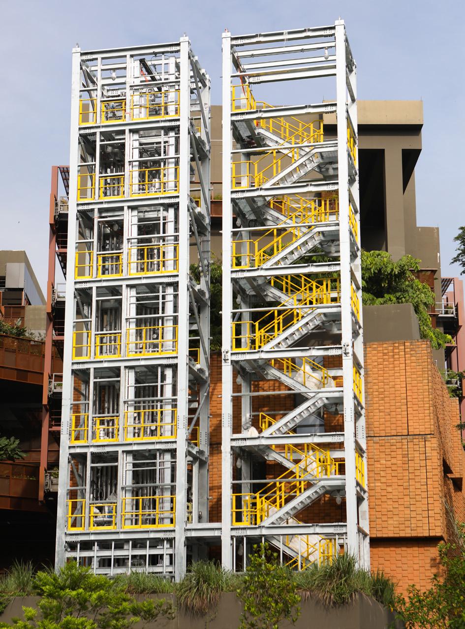
developments in other fields or responding to changing demands of the market and customers.
Sulzer’s line of structured packing is an example of this. The company’s BXTM gauze packing was first introduced in 1964, offering at that time a pioneering solution for isotope separation. By 1976 the principles behind this had evolved into the MellapakTM product line, which quickly became synonymous with structured packing in packed columns for distillation, absorption, and extraction applications across a range of operating pressures.
As industry demands grew for solutions offering higher capacity and efficiency, Sulzer responded in 1999 with its structured packing, MellapakPlusTM. This new packing generation featured an enhanced corrugation profile, reducing liquid holdup at interfaces between packing elements and significantly boosting column capacity. It set new performance standards and was followed just four years later in 2003 with the introduction of the gauze packing, BXPlusTM, which applied similar advancements to achieve minimum pressure drop in the typical operating range of gauze packing. As customer needs became increasingly precise, the company’s commitment to meeting these specialised processes led to the development of diverse structured packings, such as MellaCarbonTM for corrosive environments and MellapakCCTM for carbon capture applications.
The latest milestone in this evolutionary journey is the launch of Sulzer’s next generation structured packing MellapakEvoTM in 2024. With features designed to maximise vapour-liquid interaction and improve liquid distribution, the packing delivers up to 40% higher efficiency and 20% greater capacity than its predecessor, MellapakPlus. It requires decades of development in structured packing technology to deliver significant benefits in terms of energy savings, operational cost reduction, and environmental impact.
The evolution of structured packing is a great example of innovation – closely listening to customer feedback and pushing the boundaries of technology to meet the changing demands of the industry.
Collaboration for a greater and greener tomorrow
Sulzer Chemtech’s InTecH family of innovation technology hubs act as a global platform and centre of excellence to foster developments to the market. Strategically located in four sites around the globe, these hubs perform in-house research and development work for the purpose of the company’s product and technology innovation, and also offer test services to support customers in the development and scale-up of viable solutions.
The essence of true progress lies in collaboration – uniting diverse minds and entities towards achieving shared visions. It is the synergy of working with customers, understanding their unique challenges, and jointly crafting solutions that drives the industry forward. As companies seek to navigate the ever-evolving needs of the industries they serve, continuous innovation not only fuels business growth, but also paves the way for a more sustainable future.
Reference
1. ‘Bioplastics for a circular economy’, Nature, https://www.nature.com/articles/s41578-021-00407-8.
June 2024 HYDROCARBON ENGINEERING 36
Figure 1. InTecH Singapore pilot column, outdoor area under construction and to comply with CleanTech Three’s urban design guidelines.

AUMA PROFOX-X Learn more about our smart actuators PROFOX-X ACTUATORS RELIABILITY through DURABILITY profox.auma.com

Rebecca O’Donnell and Raghavendran Mahalingam, Baker Hughes, explain why the hot high pressure separator let down valve solution is one of the toughest applications in the hydroprocessing process.


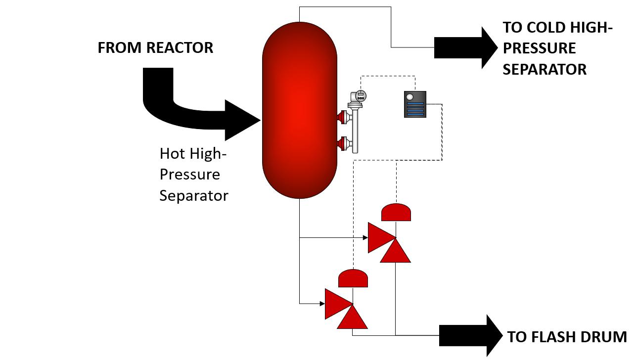
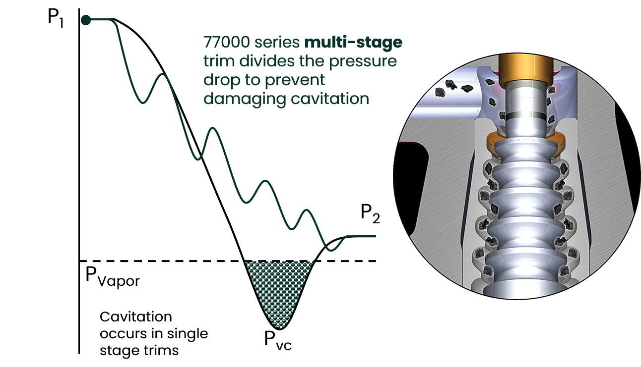
The conditions outlined below are related to the process fluid and must be considered when specifying a solution for this application:
n Process conditions should be checked for accuracy and questions should be asked about where they are being taken from. It is important to have confidence in the data. The vapour pressure is likely an average of many components, and it is essential to factor in outgassing into CV required.
n Entrained solids are small particles that are mixed in the process media and can be highly erosive especially in valve designs that have impingement points. They can also build up and clog inside areas of the valve that have dead spaces and small dimensions such as cages with small passageways.
n Off gassing is the release of entrained gases from a liquid once the pressure drops inside the valve. It can cause choking and high velocity, affecting expected CV and reducing the life of the valve due to vibration and erosion damage.
n Vibration is due to high pressure drops that cause high velocity flow after the vena contract in the valve. This leads to noise and vibrational damage inside the valve and in the downstream pipe if not accounted for.
n Corrosive media affects material selection, both soft goods and metals in the valve should be considered against the process composition. If not selected properly, the function and life of the valve can be drastically reduced.
n High temperatures up to 850°F (454°C) should be considered in the design to eliminate the chance for thermal expansion and material selection to ensure the valve holds up for as long as possible.
n Cavitation is a phenomenon that occurs in control valves once the fluid drops below its vapour pressure at the vena contracta (the smallest area in the valve that the process fluid travels through). Once the pressure of the fluid recovers above vapour pressure, cavitation occurs and can cause severe deformations in the trim areas and body of the valve.
June 2024 HYDROCARBON ENGINEERING 40
Figure 1. Hydroprocessing process diagram.
Figure 2. Hot high pressure separator letdown.
Figure 3. 77000 Series trim prevention cavitation.
Over A Century of Proven Control Valve Performance
Optimized with advanced digital instrumentation for industry leading safety and efficiency
Innovative technical solutions to meet the world’s most challenging process control applications
Trusted reliability on critical components during the harshest environments
Masoneilan... Process Controlled.

© Copyright Baker Hughes company. All rights reserved
Valve requirements include:
n Mulitstage trim for high pressure drop.
n Trash tolerant design.
n High temperature.
n Class V shut off.
n High actuation forces.
n NACE compatible materials for H 2 S.
n End connections: ring type joint (RTJ), raised face (RF) and butt-weld (BW).
n Piping considerations following the valve.
Solution
Masoneilan developed the 77000 Series valve years ago to address every challenge and aspect of this application. Still relevant today, experience, design, and material selection are key to its longevity in this process.
Features of this design include the following:
n The valve has an angle design to eliminate direct impingement points from the high velocity, multi-phase, process flow.
n The plug is double stem guided for rigidity against high pressure drops that can cause vibrational damage.
n Chrome moly and 321/347 stainless bodies for high temperatures.
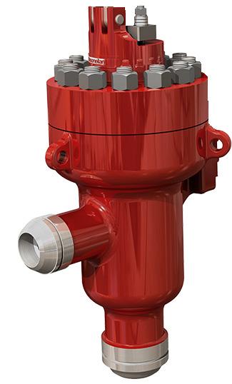

n Stainless steel/Inconel 718 with stellite overlay trim for erosion protection.
n Axial flow to allow particles to pass and not clog the valve.
n ISO-15848-1 Class AH CC3 packing certified up to 850 ° F (454 ° C).
n Sil 3 capable, meets IEC 61508: 2010 parts 1 - 2.
n Licensor approval by Honeywell UOP and Chevron Lummus Global (CLG).
n As the fluid travels across the trim, the pressure drops are taken in stages, and the area expands to provide capacity for off-gassing and to prevent choked flow.
n The plug extends to open with an upseating design that protects the seat from wear on the sealing surface, prolonging Class 5 shut off.
n ANSI 600-2500 pressure classes are available with customisable inlet and outlet sizes
Cavitation is eliminated in the 5 - 9 stage multistage trim design. As the fluid enters the valve at its highest pressure, it travels through each stage, dropping pressure until the fluid comes out of the valve, while maintaining pressure above the vapour pressure and eliminating cavitation completely.
The 77000 design includes an unbalanced plug that means no pressure balanced seals will prematurely fail or become worn due to dirty service, extending the life of the valve, allowing the design to be more forgiving of entrained particles.
Actuation forces are multiplied using the lever arm design that couples the actuator and valve together. By increasing the length of the lever arm, the forces that come from the actuator are multiplied in force to be used by the valve to overcome forces to maintain expected performance and control. The other advantage is that by using the force of the lever arm, the actuator does not have to be oversized and can stay at a reasonable size for this unbalanced design.
Conclusion
Hydroprocessing is part of both the hydrotreating and hydrocracking processes in downstream refining oil and gas operations that produces several products including jet fuel, diesel, kerosene, and gasoline. Because this unit contains contaminants and unprocessed crude, the equipment, including valves, can suffer premature wear and shortened life due to the harsh environment. As outlined in this article, each challenge and requirement should be taken into account and the goal should be a robust product that will mitigate damage or eliminate conditions that cause the valve to fail or wear out. The valve needs to function reliably for an extended period of time. Unscheduled maintenance and down time due to failing or unproperly specified valves are not accepted as they can cause production and quality issues for the site. Masoneilan has years of experience with HHPS let down valves and offers a solid product offering.
June 2024 HYDROCARBON ENGINEERING 42
Figure 4. Masoneilan™ 77000 Series top entry design.
Figure 5. Masoneilan™ 77000 Series control valve.
Desalinated seawater can serve as a reliable alternative to freshwater for industrial plants, but challenges abound. Gregory Gedney and Dave Noblin, Greene Tweed, USA, explain.


the process of desalination needs to be as efficient as possible to reduce energy waste and improve sustainability.
The water industry is not alone. Power generation, chemical, and industrial plants, which require vast amounts of water for cooling purposes, are increasingly exploring the use of saltwater for cooling systems through desalination processes. Desalinated seawater or brackish water can serve as a reliable alternative to freshwater, ensuring the continuous operation of a plant even in freshwater stressed regions.
Prepare pumps for saltwater
Saltwater, however, is highly corrosive and abrasive. Traditionally, materials such as bronze, brass and/or rubber are used for pump bearings, which do not hold up well in this type of operating environment.
The abrasive and corrosive nature of seawater, brackish water, concentrated brine, and treatment chemicals can damage pump components made of traditional materials, requiring more frequent replacement. By upgrading to components made of corrosion and abrasion-resistant composite materials, such as WR® and AR®, pump engineers can significantly lower the life cycle cost of pump operations by extending service life and reducing pump
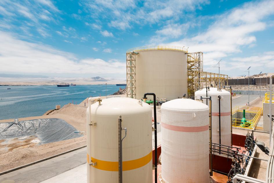

overhaul costs and maintenance expenses. AR®HT, for example, is a proprietary thermoplastic material specifically developed for use as bushings, bearings, and wear rings in pumps handling abrasive media up to 250°F (121°C). It combines excellent abrasive resistance, good dry run capability and outstanding vibration dampening characteristics with no hydrolysis or swell. Components made of this material work well in a variety of abrasive pump applications including those working with circulating water, open and closed cooling water, river water, screen water and crude oil pumps. This strategic selection of pump components will not just extend the lifespan of pumps systems, but also pave the way for a more sustainable future.
Case study
A refinery based in northeast Germany faced a number of issues caused by abrasive particles, such as sand and other debris. Designed and built in the early 1970s, the pumps in its collector wells had to be taken out of service every two years due to bearing failures. In an effort to overcome this, the refinery replaced the bearings with Greene Tweed’s abrasion-resistant thermoplastic composite AR®HT.
The material was chosen for its ability to withstand ‘off curve’ conditions, start up, dry run, high-impact vibration, and abrasive fluids. It also exhibits low friction, which was desired to prevent product flashing during upsets. The material is thermally stable and used up to 250°F (120°C). It is recommended for stationary components such as bushings, line shaft bearings, and bowl wear rings in sump or river water pumps containing sand and other abrasives.
Since the refinery fitted eight pumps with Greene Tweed’s abrasion-resistant thermoplastic composite material, it has seen excellent results. Its pumps have not required servicing since the enhancement, significantly improving mean time between failures (MBTF) to over five years. This upgrade has not only ensured uninterrupted operations but also yielded substantial cost savings, estimated at US$135 000 over six years.
Conclusion
In various industries, such as oil refineries, power stations, and desalination plants, pumps need to withstand corrosive and abrasive saltwater as well as water laden with salt, sand, and debris. Without the right materials, pumps are susceptible to premature wear, corrosion, and mechanical failures, leading to increased maintenance requirements, downtime, and operational inefficiencies. By investing in the right materials, such as AR®HT thermoplastic composite, power plants and downstream companies can mitigate these risks and ensure the reliability and longevity of their pumps.
References
1. ‘World Water Development Report 2024’, United Nations, https://www.un.org/sustainabledevelopment/blog/2024/03/ un-world-water-development-report/
2. ‘Investing in a Water-Secure Future’, Global Water Intelligence and XPV Water Partners, (5 February 2024), https://xpvwaterpartners. com/insights/news/2024/02/05/report-investing-in-a-watersecure-future
June 2024 HYDROCARBON ENGINEERING 44
Figure 2. AR®HT thermoplastic composite components ensure the reliability and longevity of pumps.
Figure 1. Desalination plants are promising to combat water scarcity.

Martin McCallister,
Delta Controls Corp., USA,
explains how a process inspection camera designed for continuous online inspection of SRU thermal reactors can help operators monitor the performance of units.
Sulfur plant operations are becoming increasingly more challenging as the industry has shifted from not only achieving environmental requirements, but also emphasising high reliability targets. As runtimes between planned shutdowns are extended, unreliability in sulfur plant operations has negative financial implications. Especially in the Claus thermal reactor, where intense operating conditions make failures more likely, methods to improve reliability will have positive effects on the entire sulfur recovery unit (SRU) performance. Increasing reliability in the Claus thermal reactor in the SRU is important as the thermal stage is prone to failure due to the intense operating conditions. Therefore, improvements made in the thermal stage are beneficial to the entire SRU performance.
June 2024 45 HYDROCARBON ENGINEERING
One method of improving process awareness is to increase instrumentation of the thermal reactor. Instrumentation, including analysers, flame scanners, and temperature indicating devices such as pyrometers and thermocouples, is often connected to the safety instrumented system and is key to understanding the process status. While these instruments provide critical process data, many unknowns remain when it comes to the health and performance of the thermal reactor. Current instrumentation cannot effectively detect damage to critical reactor components such as the burner, refractory or tubesheet protection system. Damage is often undetected until the unit is shutdown and the reactor is open for a visual inspection. While the unit is operational, an operator’s visual inspection of critical reactor components is limited to traditional sight ports, which offer a narrow field of view due to the bore diameter along the sight path. Additionally, sulfur often condenses or solidifies on the glass or in the bore, which eliminates the view.
An inside view
In the effort to increase reliability, the challenge becomes how to predict and identify a root cause before symptoms appear or are detected by current instruments. The ability to view the inside of a vessel allows operators to make pre-emptive operational decisions based on the condition of critical reactor components. High resolution images and a video feed of these reactor components provides the data required to make informed decisions, avoid major equipment failures, and reduce vessel downtime.
Delta Controls recently introduced a process inspection camera that is designed for continuous online inspection of the SRU thermal reactor and has now produced the first images taken inside an online thermal reactor.
The primary design considerations for the process inspection camera include reliability, achieving the best view of the vessel’s interior and, most importantly, safety. The view of the critical interior reactor components is optimised by placing a wide-angle lens at the refractory hot face. A number of significant challenges for this design were taken
into consideration by the design team. For example, the camera and lens have a melting point near 65°C, which requires the use of a cooling system to survive the internal operating temperature of the Claus reactor. An additional challenge was developing a probe assembly that could be sufficiently cooled while accurately maintaining a surface temperature above which sulfur would condense and occlude the lens, as well as avoid low and high temperature sulfur corrosion mechanisms (Figure 1).
To overcome the corrosion, and temperature limitations, the camera design incorporates a patent pending thermal regulation system that uses water circulated through a series of channels to precisely regulate the probe’s surface temperature. The operating temperature of the probe surface must remain between the limits of sulfur dewpoint corrosion and high temperature sulfidation corrosion, as well as maintain the internal camera circuitry within the maximum temperature limit. Furthermore, the thermal regulation system maintains the lens temperature above sulfur’s freezing point to prevent lens occlusion and accumulation on the probe surface.
The camera probe assembly is designed to be mounted on a standard process nozzle fitted with an isolation valve. The camera can be operated while a reactor is online and is either left installed indefinitely for long-term monitoring, or used for a temporary inspection. A flanged seal assembly mounts to a 3 in. (or larger) nozzle flange and incorporates multiple redundant seals to allow for the camera to insert and retract without process leakage. To ensure safety, a nitrogen supply applies a positive back pressure to the seals that is higher than the process pressure. Therefore, in the event that a seal is compromised, nitrogen would flow through the damaged seal and into the reactor. An inline flow meter would indicate flow and if a seal had been compromised. This system serves to prevent any process gas leakage and provides an indication of seal integrity.
To automate the insertion and retraction of the camera probe assembly, the camera utilises a pneumatically driven extraction system that actuates the camera into and out of the vessel through the flanged seal assembly. This system allows for failsafe features to be implemented.
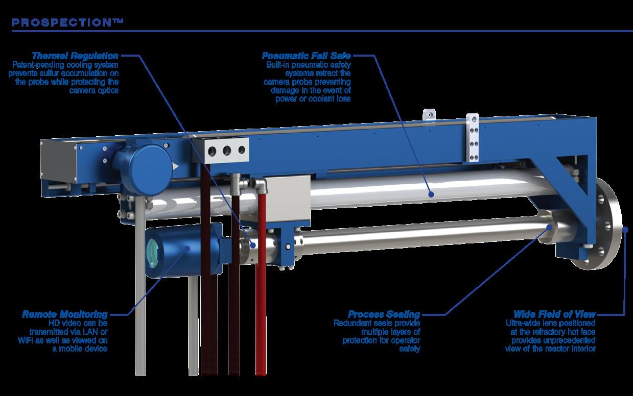
The camera can automatically order its own retraction from the process for any number of fault conditions such as loss of coolant, rising camera temperature, loss of power, or loss of instrument air.
The camera’s optical design is optimised for the incandescent environment found inside an SRU. A series of optical filters protect the camera lens from infrared energy and filter specific light wavelengths. Video and images are sent to the control room and can be set to provide continuous live video or capture still images at specified intervals.
Process inspection
The process inspection camera allows new views into online reactors that provide more information and can better guide decision-making. Critical reactor components
June 2024 HYDROCARBON ENGINEERING 46
Figure 1. The instrument incorporates several functional, reliability, and safety features.

TRI-BLOCK SIL3 DOUBLE BLOCK & BLEED VALVE www.ZwICK-aRmaTUREn.DE
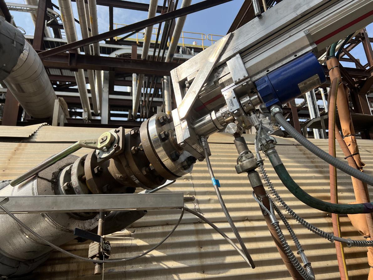


of interest include the burner, refractory lining and tubesheet protection system.
Catching early failures in any one of these areas can be of great benefit to the unit operator. Starting with the burner, continuous monitoring with a camera can provide significant data improvements over existing instrumentation. Burners are oftentimes the root cause of many larger failures seen in sulfur plants. A failing or incorrectly performing burner can not only cause poor chemistry, but also damage to the refractory, waste heat boiler, checker wall and tubesheet. Burner components can suffer from other failure mechanisms, such as back burning and the metal componentry being consumed by the flame front. Changes in the burner structure would be visible only by comparing sequential images from routine inspections using the camera.
Identifying refractory damage early can prevent major failures such as burn throughs, corrosion problems, and further refractory collapse. The camera’s wide-angle view at the refractory hot face can identify sagging or shifting within the vessel. It can also identify early stages of refractory damage such as vitrification of the refractory brick from direct burner impingement, which could lead to cracking. Many isolated refractory failures can be difficult to detect with traditional temperature instrumentation but would easily be visible with the inspection camera. Comparing images taken at regular intervals over a period of time allows operators to detect subtle shifts in the refractory. Additionally, the camera may prevent the need for a shutdown if there is a suspected problem. Users can identify problems with the refractory before it devolves into larger issues such as a shell burn through or complete refractory failure.
A final focus for camera inspection is the transition to the waste heat boiler: the tubesheet protection system, including ceramic ferrules. Regular inspection can provide insights into reactor performance and avoid major failures related to the waste heat boiler operation. Visual inspection can be used to detect staining on the ceramic tube sheet ferrules from a leaking boiler tube. Other process issues can also be detected on the ceramic ferrules such as high temperature vitrification indicating hot spots or carbon deposits indicating poor hydrocarbon destruction. Identifying problems in service will help spot any issues in the early stages and potentially prevent extensive damage of the boiler equipment.
Testing process
To complete the initial field testing of the process camera, Delta Controls partnered with a refinery in Alberta, Canada. The testing process consisted of several phases including nozzle location evaluation, equipment installation, hardware verification and software verification. Following a site analysis, the nozzle location was selected in zone 1 of the reactor with an angulation approximately 45° towards the main process burner. This orientation provided a view of the process burner componentry as well as the refractory on the burner wall. This nozzle was equipped with two isolation valves, allowing for a double block and bleed setup. The installation proceeded
June 2024 HYDROCARBON ENGINEERING 48
Figure 3. First image produced showing material deposition along the test nozzle bore.
Figure 2. The extractor and probe assembly bolted to the vessel’s isolation valve and required utilities established.
Figure 4. The process camera provides online images of the burner, refractory lining or tubesheet protection system.
with the extractor and probe assembly bolted to the isolation valve and the required utilities established as seen in Figure 2.
Initial testing consisted of verifying basic functionality of both the hardware and software. The probe was actuated to a location in the nozzle bore that was experiencing temperatures lower than the peak process temperature at the hot face of the refractory. A procedure was followed to expose the camera probe to incrementally increasing temperatures to ensure the internal probe temperature would remain within design parameters. The test team monitored and data logged critical temperatures of the device for the totality of the testing. Following the verification of mechanical performance, the software was assessed for functionality and stability.
The preliminary images produced by the inspection camera showed that the test nozzle was suffering from material deposition along the bore (Figure 3). This buildup was likely in place prior to the camera installation. After determining that the camera view and ability to insert were compromised, action was taken to clear the debris from the nozzle bore to allow full access. Once the camera was able to be fully installed in the bore, the camera was able to obtain consistent high-quality images (Figure 4). Figures 3 and 4 are some of the first images ever taken inside of an online SRU thermal reactor. Extended tests were performed over a period of weeks, including long-term tests that validated the cooling system performance when left exposed to full process temperatures for periods of 8 to 10 hours.
The tests performed verified the functionality, performance and safety of the primary camera systems. Furthermore, the data obtained on sulfur deposition on the probe body and lens advanced understanding of the required probe surface temperature parameters. As a result, the engineering team is developing protocols for thermal management, nozzle purge rate, and insertion rate to ensure sulfur accumulation is prevented. The testing also demonstrated the redundant seal design under standard operating temperatures and pressures, which is of critical importance in sulfur service. Lastly the team was able to gather significant feedback on the user interface which guides the development team for usability upgrades and the addition of software features.
Conclusion
Field testing of the process inspection camera validated the functionality and safety of the instrument while also providing valuable data for product improvement. The camera allows operators to make more informed operational decisions and potentially avoid shutdowns and equipment failures. Preventing unnecessary downtime using photo or video inspections will lead to large cost savings. In addition, reactor inspections can now be carried out without reactor shut down, allowing users to shorten turnarounds with fewer surprises in the thermal reactor. New process inspection cameras will be of significant value to the sulfur processing industry by providing more data about online reactors than previously available.
Enhancing the reliability of the sulfur plant starts in the thermal stage. Now, plant operators can shorten downtime, avoid major equipment failures, and make more informed decisions with advanced inspection cameras.
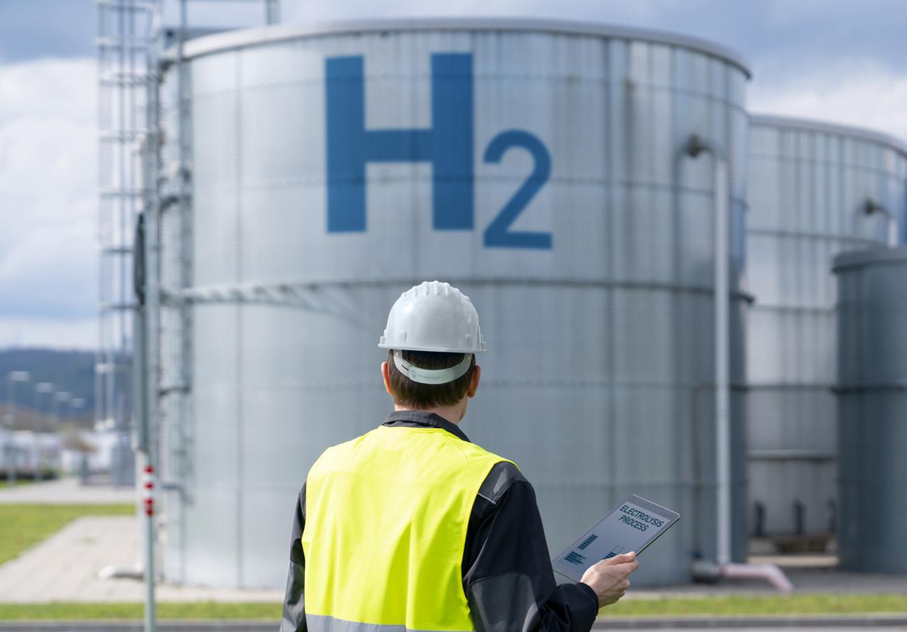
Ejectors for Green Hydrogen production.
GEA jet compressors and ejectors are a reliable tool throughout the production process of green hydrogen, helping ensure its purity and quality. They are also the ideal way to deal with hydrogen’s explosivity.
Other applications of GEA liquid jet compressors and ejectors are:
• Production of phase analysis (H2) green ...hydrogen fuel cells.
• Hydrogenation processes.
• Biogas CO2 mixtures and loop-reactors.

Transfoming Tomorrow Join GEA at ACHEMA ‘24 Hall 4 Booth G66

Subscribe online at: www.energyglobal.com/magazine
The premier source of technical and analytical information for the renewable energy industry, covering solar, wind, and energy storage. ENERGY GL BAL

Christian Chanel, Integrated Global Services (IGS), USA, presents a guide to optimising convection section performance in ethylene furnaces.
Fouling in petrochemical manufacturing plants, particularly in ethylene plants, has become a primary concern due to its negative effects on plant throughput, energy requirements, environmental implications, and product quality. Process fouling within heat transfer equipment accounts for significant economic losses, costing industrialised nations up to 0.25% of their Gross National Product (GNP).
Fouling in the convection sections of an ethylene plant exacerbates greenhouse gas (GHG) emissions and poses serious safety hazards. The energy intensity of an ethylene cracker exacerbates this problem, with an increase of 50°C above design stack temperatures resulting in an efficiency loss of 1.5 - 2.0%. Considering a plant section with five operational furnaces, it is estimated that a robotic clean could result in a
June 2024 51 HYDROCARBON ENGINEERING
cumulative saving of US$5.44 million over a three-year period.
Temperature control and the cracking process
To achieve the correct cracking of hydrocarbons, ethylene furnaces maintain a temperature of approximately 2000°F (1093°C). A narrow band of temperature range is vital for successful cracking. The reactions involved are endothermic, demanding a substantial amount of energy.

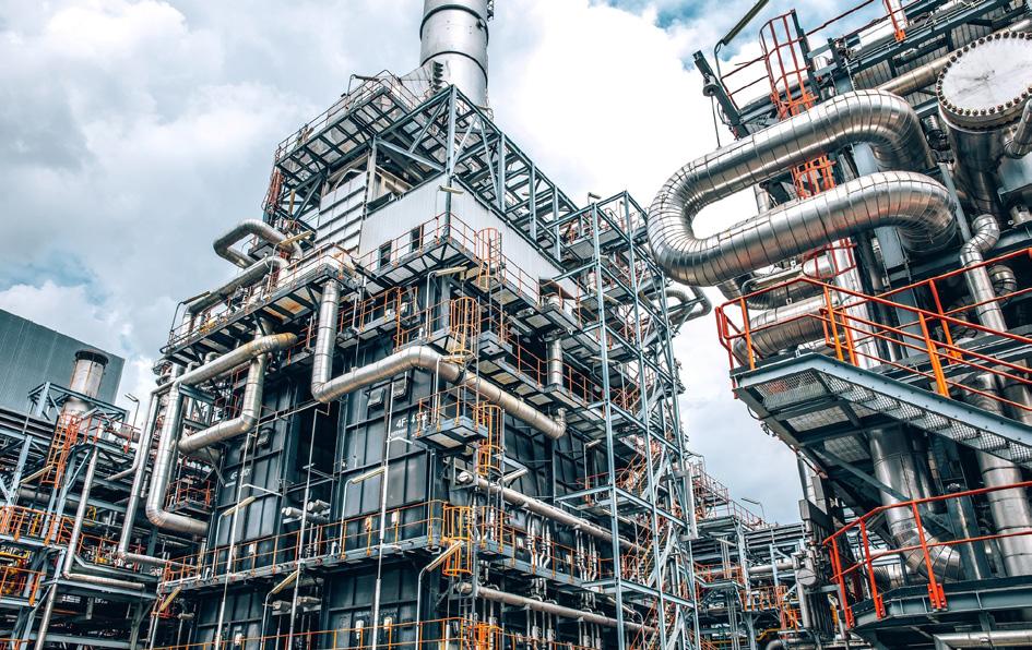
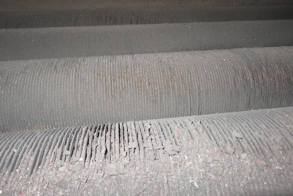
However, due to the exceptionally fast cracking process, the light feed must be exposed to this intense heat for only milliseconds, allowing conversion to ethylene and propylene without promoting coke formation.
The role of the convection section
The convection section serves as the vital pre-heat mechanism in ethylene furnaces, ensuring the correct temperature range is achieved. Deviating from this range can lead to inefficiency and limited conversion if the temperature is too cold, or excessive coke formation if it becomes too hot. Maintaining an optimal flow rate is equally important to prevent overheating the product and generating coke.
Consequences of fouled convection sections
When fouling occurs in the convection section, heat transfer becomes limited, resulting in an inefficient pre-heat process. To compensate, additional firing and fuel consumption is required to reach the desired temperature. This has a knock-on effect and overheats the radiant section, leading to potential complications. The energy intensity of an ethylene cracker is such that a 50°C increase above design stack temperatures, as witnessed in a fouled furnace convection bank, can result in an efficiency loss of 1.5 - 2.0%.
The solution: automated rover system
The use of pre-programmed robotics offers a safer step-change improvement over more mature manual lancing systems. The use of customised robots allows 90 - 95+% surface area cleanliness of convection banks between every tube row, regardless of fouling levels with cleaning standards verified using real-time digital video capture.
IGS Tube Tech offers robotic cleaning systems which use proprietary lance and nozzle technologies to achieve very close tube surface contact in situ.
The versatile robots are used with air and high-pressure water. While very high pressures are involved, e.g. up to 1000 bar (15 000 psi), the total volume of water is much lower than standard hydroblasting.
There is minimal risk of refractory damage as the rotary jet on the lance is specifically angled towards the finned tubes. The robot has sensors which are programmed to stop prior to the refractory wall. The absorption rate of water during Tube Tech robotic cleaning service has been examined in a collaborative report based on trials around the world.
Case study
Furnace description
A cracking furnace functionally is divided into three zones: radiant section, convection section, and transfer line exchangers (TLEs). TLEs are placed vertically, with cracked gas in the inner pipe (tube side) and boiler water/steam in the outer pipe (shell side). TLEs are waste heat boilers (WHB) placed at the outlet of the radiant coils to rapidly
June 2024 HYDROCARBON ENGINEERING 52
Figure 1. The robotic IGS convection section cleaning system.
Figure 2. Fouling in ethylene plants has become a primary concern due to its negative effects on plant throughput, energy requirements, environmental implications, and product quality.
Figure 3. Fouled convection section tubes before cleaning.
reduce the cracked gas temperature to mitigate secondary reactions by producing saturated very high pressure (VHP) steam.
Radiant section
The firebox is a rectangular, refractory-lined volume within which the radiant coils are suspended vertically, firing from the bottom. The radiant coil, in this case, is short residence time (SRT) type, favouring selectivity towards ethylene production. Two fireboxes have a common convection section, so the performance of the convection section influences two radiant chambers at the same time.
Convection section
The convection section is located above two fireboxes. The services of the different heat transfer banks shown in Figure 1 include:
n Mixed feed preheater (MFPH-I).
n Economiser (ECO).
n Cold high-pressure steam superheater (CHPSSH).
n Hot high-pressure steam superheater (HHPSSH).
n Mixed feed preheater (MFPH-II).
Case description
Over the last six years in operation before cleaning, the stack temperature rose from 190°C to 230°C, equalling 2.0% losses in fuel efficiency.
The purpose of this project was to reinstate the overall fuel efficiency, save fuel and cut emissions. Unfortunately,

windows in the convection section were not designed to provide access to any type of fouling removal equipment.
Solution
To perform effective heat transfer restoration using a unique remotely operated vehicle (ROV), fouling removal technology and protect the existing equipment from water exposure, the following three steps have been implemented:
n New access openings have to be created to enable placing an ROV on top of each convection bundle.

 Figure 4. After the robotic convection section system cleaning process.

n The radiant box has to be isolated.
n All effluent and debris after fouling removal has to be collected and displaced to the ground level in sediment containers.
Key benefits
The ROV technology entirely removed fouling from the convection bank coils. The system removed 90+% of fouling from all convection bundles.
No refractory was damaged since ROVs are programmed to direct a high-pressure medium to the tubes only. All activities were done in 4 x 12-hour shifts.
A 40°C drop in stack temperature was achieved. The plant reported a two percentage points increase in overall fuel and a payback period of fewer than four months.
Acknowledgments and new data two years after cleaning
Heat distribution between c/s and r/s is crucial in coking-sensitive services. Keeping the convection section surface clean helps save fuel, increases steam generation and positively influences the steam cracking process. The achieved benefit was cca. 16 000 MWh/year fuel savings and 2500 tpy of CO2 reduction (fuel is CH4/H2 mixture). Due to higher crossover temperature (radiant inlet temperature), the residence time will be slightly less, with an additional opportunity to make more ethylene due to enhanced selectivity.

After almost two years, the client reported a slight elevation in stack temperature of 10°C and a stable efficiency increase of 1.5 percentage points. The next fouling removal project is anticipated after six years to reinstate the efficiency again.
To make the obtained benefit long-lasting, IGS also recommends a combination of the Tube Tech ROV cleaning with Cetek’s proprietary ceramic refractory coatings to protect and encapsulate the ceramic fibre and stop refractory deterioration and new fouling formation on the outside surface of the convection tubes.
Commercial impact of the project
The plant reported a two percentage points increase in overall fuel efficiency from 89.5 to 91.5 on average, leading to 2 MW fewer combustion losses. The plant has reported a payback period of fewer than four months. A 40°C drop in stack temperature was achieved.
Conclusion
Optimising the performance of ethylene furnaces is critical for industries aiming to achieve maximum efficiency in ethylene and propylene production. By maintaining the correct temperature range, monitoring flow rates, and mitigating fouling issues in the convection section, facilities can ensure smooth operations, enhance safety, and minimise downtime, ultimately elevating their overall production output.


Liquid water measurements. Solid reliability
.


• User-friendly design and minimal maintenance Reliability, redefined


Designed for hazardous areas, the rugged SERVOTOUGH SpectraExact 2500F brings a new level of precision to liquid water measurements.
• Flexible, real-time, on-line process analysis
• Accurate and reliable ppm to percent water measurements in solvents
• Handles corrosive, toxic, and flammable streams
Measure water in solvents to the next level: servomex.com

E. M. Ishiyama, D. Oakley, J. Kennedy, S. J. Pugh, and H. U. Zettler, Heat Transfer Research Inc. (HTRI), discuss the advantages that digital innovations can offer in tackling challenges faced by contemporary refineries during the energy transition.
In the peak of the Industry 4.0 era, digital transformation has evolved in the process industries from an optional strategic decision to a foundational element crucial for sustainable success. Instead of simply adopting technology, companies are embracing the comprehensive integration of digital platforms that ensure operational effectiveness, economic efficiency, and environmental stewardship. Such platforms play a vital role in improving performance monitoring, facilitating predictive analytics, optimising operations, and enhancing safety measures within the process industries.
June 2024 55 HYDROCARBON ENGINEERING
This article presents two illustrative case studies. The first examines the thorough monitoring and forecasting of furnace performance during transitions in fuel use, while the second investigates the early detection and resolution of issues related to fouling-induced vibration. Utilising advanced commercial software tools such as HTRI SmartPMTM, Xfh® Ultra, and Xist®, the tangible advantages that digital innovations offer in tackling the complex challenges that contemporary process industries face will be illustrated.
In process industries, the twin goals of operating heat transfer equipment efficiently and safely stand out as critical objectives. It is essential to differentiate between operations that are merely economically beneficial and those that excel in quality and performance. The use of comprehensive performance evaluations, which include validated heat transfer, pressure drop, and vibration analysis using sophisticated equations and methods is vital for creating accurate digital twin models. These models act as virtual counterparts to physical systems, allowing for continuous monitoring and fine-tuning of operational efficiency.
Digital twins are indispensable in maintaining safe operations – for instance, by tracking fouling and slagging in fired heaters or
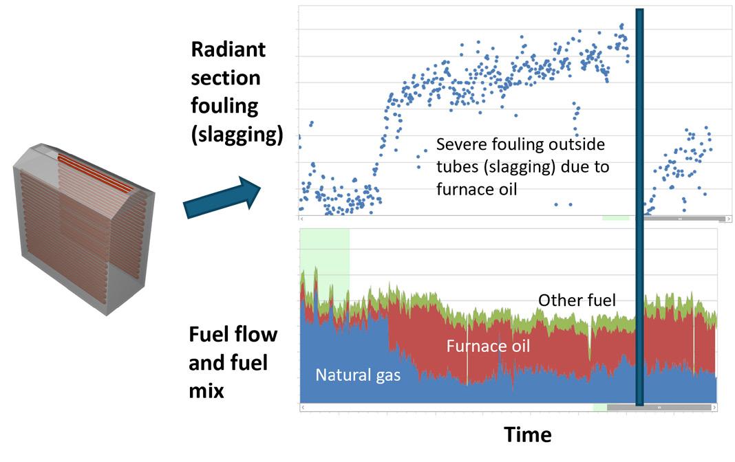
spotting potential flow induced vibration issues in heat exchangers. Keeping an eye on important indicators (e.g., vibration levels and critical temperatures) and recognising signs of fouling – a buildup of undesired materials on equipment surfaces that can drastically reduce efficiency – are crucial tasks. Damaging vibration or excessive fouling, if left unchecked, can lead to emergency shutdowns for repairs or cleaning. The proactive use of rigorous digital twins and analytical tools offers a significant advantage by identifying the best timing for these shutdowns, thereby minimising disruptions to production and maintaining high safety standards.
Case study 1
In 2023, the refinery landscape in the US comprised 123 active refineries, collectively processing an average of 17.7 million bpd of crude oil.1 This massive operation translates to approximately 2500 fired heaters in action within these refineries, with larger facilities potentially managing between 20 to 40 heaters each. Beyond the petroleum sector, the chemical industry operates around 1400 additional fired heaters, including roughly 700 dedicated to high-temperature pyrolysis for producing ethylene and propylene and about 350 for steam reforming hydrocarbons. These critical components boast a service life ranging from 20 to 50 years, underscoring their durability and importance in industrial applications.
Monitoring and optimising these heaters is crucial to ensuring both efficiency and safety. Modern practices involve direct connections to data historians, collecting comprehensive operational data such as crude mass flow rates, inlet and outlet temperatures and pressures, fuel types and their respective flow rates, fuel gas compositions, and critical temperatures like the bridge wall temperature.2 Advanced modelling techniques, including well-established single-zone methods for firebox simulation and incremental approaches for analysing flue gas temperatures in the convection section, play a pivotal role in this process.
A comprehensive health check module for fired heaters assesses several key areas:
n Safety assessments:
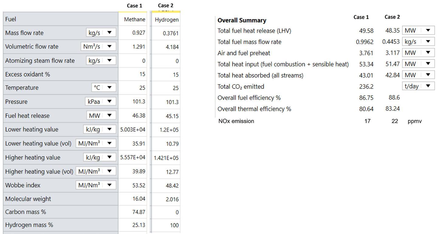
§ Monitors bridge wall and tube skin temperatures.
§ Detects fouling/slagging.
§ Assesses acid dew points.
§ Evaluates tubeside flow regimes.
n Environmental impact tracking:
§ Tracks emissions of CO2, SOx, NOx
§ Monitors flue gas exit temperatures.
n Operational metrics evaluation:
§ Evaluates heater duty.
§ Assesses efficiency.
§ Examines hydraulics.
§ Draft profile.
§ Flue gas temperature profiles.
§ Tube skin/film temperature profiles along the tube length.
June 2024 HYDROCARBON ENGINEERING 56
Figure 1. Example of fouling monitoring in a section of the fired heater with changing fuel composition.
Figure 2. Evaluating the performance impact on fired heaters: methane (case 1) vs hydrogen (case 2).


VIRTUAL CONFERENCE 5 SEPTEMBER 2024 Register for free
Fired heaters are often tasked with burning low-grade fuels not suitable for sale, such as fuel gases with variable heating values, dense furnace oil, or even waste fuels. These fuels may contain impurities like sulfur, sodium, and vanadium, leading to the formation of corrosive molten ash that accumulates on the heater tubes and supports. This scenario highlights the intricate balance between maximising operational efficiency and maintaining stringent safety and environmental standards, a challenge that today’s refineries and chemical plants navigate with the help of sophisticated monitoring and optimisation technologies.
In this case study, a fired heater in a European refinery used a combination of fuel sources: natural gas, furnace oil, and another gaseous fuel, as illustrated in a fuel supply chart (Figure 1). The choice of these fuel types was largely dictated by what was available on site, with a preference often shown toward avoiding liquid fuels due to their more complex handling requirements. Liquid fuel usage involves intricate processes including atomisation, vaporisation, and mixing with combustion air, each introducing additional potential for operational failures.
The chart depicts a significant shift in fuel usage patterns, with a marked increase in furnace oil consumption coupled with a decrease in gaseous fuels. This pivot towards heavier fuel oil usage emerged as a key factor influencing the behaviour of gas-side fouling. Composition data was imported directly from the facility’s data historian to track the variation in fuel gas composition, subject to its source and processing.
The issue of fouling and slagging on the external surfaces of tubes was further evidenced by the necessity of cleaning these surfaces only during shutdown periods. Subsequent monitoring revealed that thermal resistance values returned to baseline levels after cleaning, only to begin rising again, underscoring the ongoing challenge of managing fouling within these complex systems.
Digital twin technology facilitates the exploration of various ‘what if’ scenarios, including the potential effects of switching to a hydrogen-based fuel system. This analysis is conducted after a plant shutdown and subsequent cleaning, comparing the existing fuel setup with a hypothetical transition to hydrogen. Known for its clean combustion properties, hydrogen is expected to reduce fouling and slagging on the gas side. The implications of such a transition are detailed in Figure 2, where Case 1 involves the use of 100% methane fuel
and Case 2 explores the use of 100% hydrogen as fuel, highlighting several critical observations:
n An increased volumetric flow rate of fuel indicates the necessity for infrastructural enhancements, particularly within the piping system, to accommodate the new fuel supply.
n A modification in the Wobbe index exceeding 5% requires an investment in upgraded burners to ensure a stable and consistent heat output.
n The transition to hydrogen, with its inherently higher adiabatic flame temperature, poses a risk of augmented thermal NO x formation, Adopting advanced emission control strategies would mitigate this effect. Usage of low-NO x /ultra low-NOx burners are examples of pre-combustion control techniques; however, this results in increased flame length and the suitability of such techniques need to be assessed based on individual heater design.
n While the switch to hydrogen may eliminate gas-side fouling and diminish CO2 and SO2 emissions (relocating these emissions to the centralised hydrogen production facility), the elevated flame temperatures could increase the radiant section’s heat flux and tube wall temperatures. This scenario raises concerns about the potential for increased fouling/coking inside the tube.
Case study 2
Studying the impact of fluid dynamics on equipment durability and safety reveals the complex phenomenon of thermo-hydraulic channelling.3 If not adequately managed, this process can reduce thermal efficiency and present equipment safety challenges.4 This case study involved two parallel heat exchangers within a crude preheat train, revealing the critical balance between fluid flow and equipment integrity. Vibration, a common issue in any equipment where fluid flows, could escalate into mechanical failure due to wear, corrosion, and fatigue. The safety thresholds for these vibrations, distinct from thermal or hydraulic performance concerns, became evident when examining the digital twin model of these exchangers.
The study contrasted two exchangers: EX1A, with crude oil flowing through its tubes, and EX2C, with crude in the shell (Figure 3a). The simple heat exchanger network model was constructed via SmartPM, and EX2C was connected to Xist (Figure 3b). Notably, the crude stream divided and flowed through these exchangers without flow control, adjusting spontaneously to balance pressure drops. This spontaneous flow behaviour, particularly under the severe fouling conditions of EX1A compared to the minimal fouling in EX2C, led to divergent flow patterns (Figure 4a) that posed a risk of flow-induced vibrations.
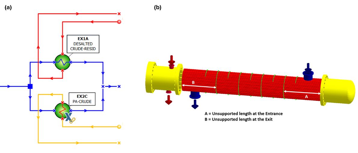
Utilising the fluidelastic instability ratio (FIR) to monitor vibration risk, this case study predicted potential vibration issues within six months, with the severity increasing over time if no corrective actions were taken (Figure 4b). This foresight enabled operators to implement preventative measures, such as fouling mitigation in EX1A, flow adjustments, and structural support enhancements in EX2C, to ensure the continued safety and
June 2024 HYDROCARBON ENGINEERING 58
Figure 3. Example of (a) two heat exchangers in parallel and (b) 3D representation of EX2C with the longest unsupported tube length at entrance (A) and exit (B) sections.

Performance monitoring and predictive maintenance software for shell-and-tube heat exchanger networks
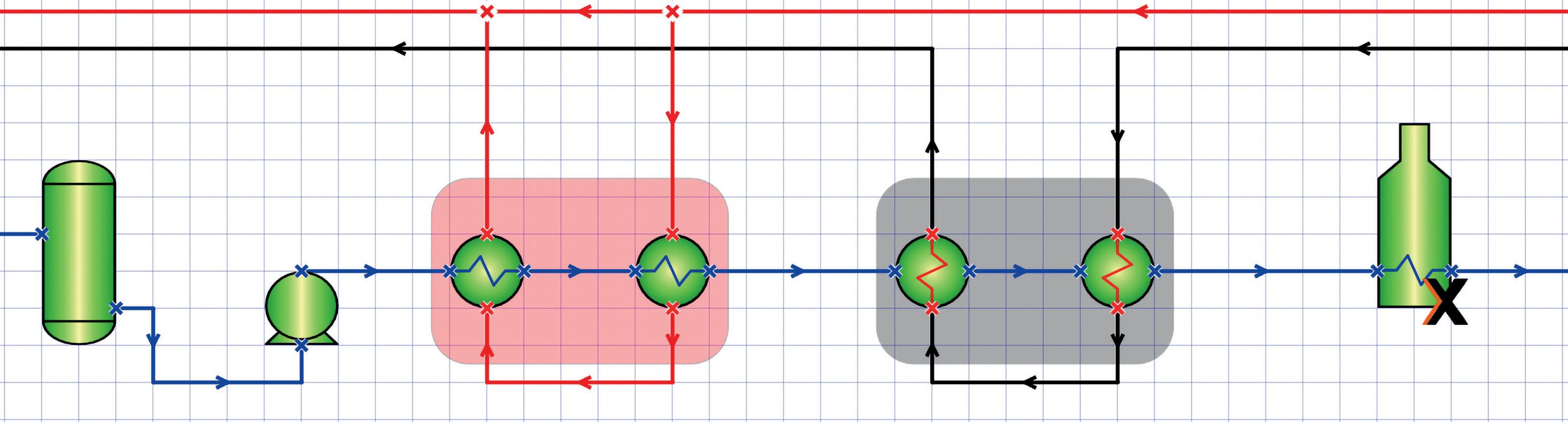

HTRI SmartPM is an innovative digital transformation tool that revolutionizes the way you monitor and optimize your heat exchanger systems. With SmartPM, you can see holistic performance views of your fouling heat exchangers and fired heaters track performance through the dynamic dashboard and interactions with data historians employ data-driven, research-based AI prediction capabilities improve heat exchanger and fired heater cleaning strategies optimize heat recovery analyze retrofit and revamp options reduce fuel consumption and emissions
Harness the power of HTRI’s detailed heat exchanger technology in robust digital twin models.

HTRI.NET/SOFTWARE/SMARTPM
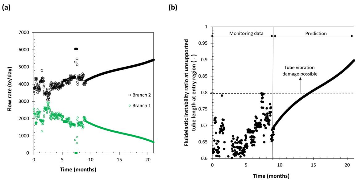
Figure 4. Illustrations of (a) monitored and predicted flow rates across branches 1 and 2 (in Figure 3a) and (b) FIR for the entrance region of EX2C (marked ‘A’ in Figure 3b).
efficiency of the operation. Through this case study, the interaction between fluid dynamics, equipment design, and operational strategy unfolded, highlighting the importance of predictive analytics in maintaining industrial safety and performance.
Conclusion
Applying digital twin technology and exploring alternative fuels like hydrogen is essential for process industries to address operational and environmental challenges today. The case studies presented – ranging from mitigating vibration issues in heat exchangers to evaluating the impacts of fuel
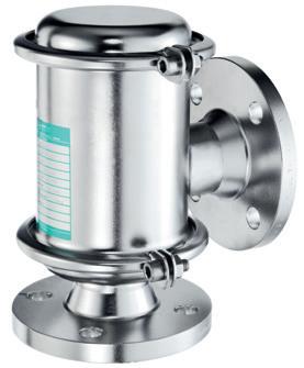

transitions on furnace operations – showcase the critical role of digital innovations in optimising performance and ensuring safety. Transitioning to cleaner fuels, while beneficial for reducing emissions and fouling, brings additional infrastructural and operational challenges that require strategic planning and investments.
A balanced approach must consider both the potential environmental benefits and the operational complexities of such transitions. As industries strive to align with global sustainability goals, integrating advanced digital analysis with what-if studies of novel technologies and cleaner fuels emerges as a key strategy for enhancing efficiency, reducing emissions, and maintaining high safety standards.
References
1. ‘Number and capacity of petroleum refineries’, US Energy Information Administration (EIA), https://www.eia.gov/dnav/pet/pet_pnp_cap1_dcu_ nus_a.htm (March 2024).
2. PETROPOULOU, E., GIAMALAKIS, D., SPIRIDAKi, G., ARISTEIDOPOULOU, A., PLELLIS, C., LOUKOPOULOS, S., OAKLEY, D., KENNEDY, J., and ISHIYAMA, E.M, ‘Impact of fuel selection on gas-side fouling in fired heaters: A techno-economic-environmental analysis’, in Proc. Heat Exch. Fouling Cleaning XV, 55-63, Lisbon, Portugal, (2024).
3. ISHIYAMA, E. M., PATERSON, W. R., and WILSON, D. I, ‘Thermohydraulic channelling in parallel heat exchangers subject to fouling’, Chem. Eng. Sci. 63(13), 3400-3410 (2008), https://doi.org/10.1016/j. ces.2008.04.008
4. ISHIYAMA, E. M., KENNEDY, J. M., ZETTLER, H. U., and PUGH, S. J., ‘Fouling management through digital transformation’, in Proc. Heat Exch. Fouling Cleaning XIV, Wagrain, Austria, (2022). https://heatexchanger-fouling. com/wp-content/uploads/2023/01/S10-1000-Thursday-Pugh_a-1.pdf


REMBE® Your Specialist for Pressure Relief Solutions. © REMBE® | All rights reserved rembe.com hello@rembe.com 9567 Yarborough Rd. | Fort Mill, SC 29707, USA T +1 704 716 7022 hello@rembe.us

Chelsea Hogard, Watlow, USA, considers the importance of data insights in mitigating the risks associated with process heating and aiding the transition to more efficient systems.
Process heating is a critical part of hydrocarbon processing. Traditionally, this heating has been achieved by burning fossil fuels (natural gas), but increasingly plants are turning to electric process heaters. One of the benefits of doing so is that electric heaters allow for more precise control of both the heating element surface temperature and the power draw of the system.
This is not just the ability to tweak the settings of the thermal system at any given moment. The kind of control that can be afforded today is predictive control, which is made possible by having actionable insights based on data.
This kind of predictive control has been a goal throughout the development of Watlow’s WATCONNECT control panels; an integrated solution that includes heaters, sensors, temperature controllers and power controller products, in a complete thermal loop solution.
Predictive control is enabled by the Data Insights package offered with the control panels. This enables the control panel to track power and controller health, as well as monitor system changes over time.
Overcoming process heating problems
This kind of data enables engineers to get ahead of some of the most pervasive problems in process heating in the industry including, coking/fouling,
June 2024 61 HYDROCARBON ENGINEERING
heater failure (and the ensuing downtime), and the need for electrification to reach decarbonisation goals.
Coking/fouling
Petrochemical refining operations often use heat exchangers in processes that are conducive to coking and fouling. Fouled heaters can contaminate or disrupt processing, and therefore must be cleaned and/or replaced. Data insights can monitor the system for drift that could be indicative of coking/fouling or other degradation in the system, signalling the need for maintenance.
Heater failure and downtime
It is a fact of physics that heater elements occassionally fail. Continued failure of an element eventually leads to an inability to produce enough heat to reach (or sustain) the intended outlet temperature. This can cause further issues with the process in question, including incomplete processing and/or fouling or film boiling. Being able to
detect when an element has failed can avoid more serious problems that lead to unscheduled maintenance.
Electrification
Process heating is a significant source of energy use and greenhouse gas emissions in the industrial sector, and so replacing fossil fuel based heaters with electric ones running on green energy should yield significant progress towards decarbonisation goals. Adopting solutions for the first time will naturally bring about questions in the minds of process end user engineers – questions about process variation, network loads, component failure, and more. Modern data collection technology, along with sophisticated data analysis, can monitor processes and allow these kinds of questions to be answered in real time.
Mitigating these particular problems requires two things: first, the ability to collect the right kinds of data, in real time, and second, the experience to make sense of that data and take action in a timely manner.
Collecting the right data, in real time
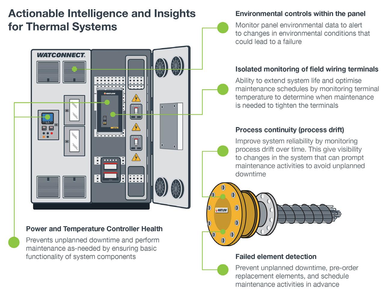
Figure 1. Actionable intelligence and insights for thermal systems available with control panels and data insights.
Process variation/drift Record variation between cycles for proactive intervention. Compare and correlate thermal profile to plant metrics and benchmarks. Alert appropriate parties when there is process drift outside of defined set range.
Energy consumption and network load
Capture process drifts and record their impact on energy consumption. Use real-time power control to stabilise load.
Component failure Detect failed (or close-to-failing) elements and pre-order replacements. Schedule maintenance activities in advance of element failure.
Maintenance and reliability
Optimise timeline for product managers (PMs) and system checks; improve overall reliability and uptime.
Having the right kinds of data about systems and component operation and health mitigates many of the risks that come with implementing new technology. To take the first example from above, detecting temperature drift in a process can often indicate coking or fouling that will cause future maintenance issues. If a process end user operator can detect a pattern of drift that signals that this problem is imminent, then unplanned downtime can be avoided with a planned maintenance cycle.
WATCONNECT panels equipped with Data InsightsTM enable this kind of detection, as they constantly collect data relating to system power (current and voltage), process values, set points, panel environment, and even wiring terminal temperatures. This enables the panel to, in effect:
n Monitor power and temperature controller health.
n Detect failed elements.
n Detect and monitor process drift over time.
n Monitor panel environmental data and alert appropriate parties to changes in environmental conditions that could lead to a failure.
n Monitor field wiring terminals optically and prompt for maintenance to tighten terminals.
Table 1 goes into greater detail about the particular ways that Data Insights can afford proactive solutions for these engineering challenges.
June 2024 HYDROCARBON ENGINEERING 62
Event to detect and monitor Proactive data-driven solution
Table 1. Proactive solutions offered by control panels
Making sense of the data: analysis
If the solution to the above challenges were simply ‘collect more data’, then those challenges would be solved already. Most organisations are awash in data these days, or at least have access to technology that can be used to gather it. What is needed is the ability to make sense of that data. For example, consider: what kinds of process drift (and over what time periods) are truly indicative of coking? What sorts of patterns of power consumption show that some heater elements are over-compensating for a failed one? When do changes in the panel environment merit immediate intervention?
These are the sorts of questions that can only be answered through extensive experience with the data as it pertains to real-world systems. This is why a full data service as part of a Data Insights package is vital. When raw data is provided, it is not always clear how to make that data ‘actionable’. But when process data is analysed by a data scientist and a thermal system expert, together they can provide insights and make recommendations for system improvement. By collaborating with engineers that are familiar with the industry application in question, they can then help put the data into context.
This kind of collaboration has proven to be a time-saver as well. Data Insights can enable a team to keep a close watch as the data comes in, freeing the end user so that they can maintain their focus on critical process parameters and key performance indicators (KPIs). The end user can be alerted when action is required while removing the need to
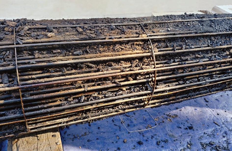
constantly check and recheck data dashboards. This data analysis provides a complete solution for a reliable electric heating system.
Conclusion
In summary, predictive control of process heating can help mitigate some of the challenges that are common in petrochemical processing, including coking/fouling, heater failure/downtime, and the slow pace of electrification. Achieving predictive control requires the right combination of new technology and technical knowledge around thermal systems and data analysis. When both are in place, it paves the way for greener, more efficient systems and processes.
EMPOWER ASSET PERFORMANCE MANAGEMENT AND DIGITAL TWINS
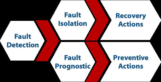
CLUE is the AI based solution that supports you in the management of your assets by providing:
✓ Equipment health status awareness
✓ Early anomaly detection
✓ Anomalies Correlation
✓ Root Cause Analysis
✓ Prediction of the Remaining Useful Life

 Figure 2. Example of coking/fouling in petrochemical processing.
30+ years experience in Consulting Simulation services Modelling and diagnostic software for process plants and machines www.sate-italy.com Santa Croce 664/a - 30135 Venezia - Italy info@sate-italy.com - ph. +39 041 2757634

C. Brighenti, A. Brighenti and M. Ricatto, S.A.T.E., Italy, explain the journey to increased autonomy for hydrocarbon processing plants.
The increasing complexity of industrial systems and the requirements for environmental impact limitation and safety pose significant challenges in terms of managing operations processes within a plant, which encompass field operations/maintenance, control room operation, planning and scheduling. These processes already involve a level of automation (e.g. by automatic control systems) but also present high levels of manual tasks, often due to the costs required to automate them. These include new infrastructure costs (e.g. sensor networks, communication, data management), or costs due to the need to maintain and increase the

production flexibility, which may be better managed by assisted manned supervision. However, the complexity of systems, together with the long-lifetime and availability requirements, become highly demanding for human operators, who require solutions that can help them to support the repetitive tasks under uncertainties or unpredicted conditions.
Autonomous plants
The ability to achieve system performance and integrity goals in a variety of environments and to adapt behaviour in uncertain or harsh environments without human
June 2024 65 HYDROCARBON ENGINEERING
intervention are key features of intelligent or autonomous systems, differentiating them from ‘automatic’ systems. For example, the control systems support task automation, but are not sufficient to achieve autonomy. In fact, they are able to quickly and efficiently respond to pre-defined events, or a series of events, with no human intervention or imposition. However, most of the time they do require human supervision when novel situations (usually emergency or unforeseen conditions) emerge.
This difference is represented in Figure 1, where the loop in classical control systems is compared against the loop in autonomous systems.
Several industrial fields (such as the automotive and maritime fields) are undergoing the challenging process of increasing systems autonomy, identifying the current autonomy status and setting short, medium and long-term goals. Autonomy levels are used for this purpose, a typical example being the SAE J3016 levels for driving automation (a generalised example is given in Table 1).1
Achieving higher systems autonomy encompasses the definition of all the key tasks or features that can contribute to this goal and the operative scenarios in which autonomy applies. Following the high-level definition in Table 1, an intelligent plant should have the capabilities of routine operations without requiring direct input or control from humans, real-time supervision and reaction to unexpected events, self-diagnosis of its components, evaluation and forecasting of its state (e.g. for human supervision and long-term decision-making).
It is possible that the system may achieve higher autonomy levels in specific tasks (e.g. health monitoring, fault detection and recovery) than in others. In addition, the current level of autonomy for each key task should be assessed and the opportunity to improve upon it should be analysed through a cost-benefit analysis. It is important to remember that the goal is to reduce repetitive human work tasks to preserve and empower human skills in tasks requiring creativity, intuition and expertise.

The path towards autonomous plants
The implementation of an autonomous system has to overcome several challenges, which cover technical, legislative and safety aspects.
From a technical point of view, the main challenge is in the implementation of new decision-making concepts based on software technologies, including artificial intelligence (AI), which can bring great advantages but also needs to be properly designed and validated in operations. One of the main objectives will be finding the approach to validate and ensure the proper shift from pre-programmed responses to known events, to automatic responses to unpredictable events.2 This modularisation will be essential to cope with high levels of complexity and interaction among systems in the same plant.
It is clear that the increased autonomy will require adjustments of the operations workflow, not only to reduce the manual tasks that will be in charge of the intelligent systems, but also to ensure that the automated processes and decisions are interpretable by engineers and operators. Furthermore, it will require solutions for handling the amount of additional data that will be generated by these new decision-making technologies.3
From a legislative and safety point of view, issues connected to AI and autonomy are also foreseen. Regulators still require a human to be present for many operations, including a system restart. Industry is accumulating evidence that autonomous operations can be carried out safely, and this will form the basis for revised regulations. However, not all events will have a solution that avoids damage to facilities and the environment or fatalities, leading to potential ethical conflicts that will need to be resolved.2
All of the above will result in investments in infrastructure (sensor networks, communication infrastructure4), in software solutions (implementing the decision-making concepts), and in procedures that will redefine not only the role of the human in the loop, but also the verification process to be performed for the adoption of the autonomy in safety-critical systems.
In addition, the adoption of new and unfamiliar technologies in the hydrocarbon industry will require a culture change from companies in order to integrate personnel with the right skills to understand and properly manage these new technologies, taking into account the experience that already exists in this industry with regards to the remote operation of gas production facilities, for example.
AI-based solutions as autonomous plants enablers
AI can be one of the key enabling technologies for plants to reach autonomy goals in specific functionalities. In fact, AI-based solutions have already proven to be effective at helping humans complete repetitive tasks and by reducing the time required for complex investigations into huge amounts of data.
For instance, the capability of AI to identify repeating patterns or a chain of events in a large volume of data that leads to specific anomalies can be crucial for recognising
June 2024 HYDROCARBON ENGINEERING 66
Figure 1. Loops in classical control systems (inner) and autonomous systems (outer).3


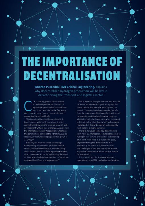


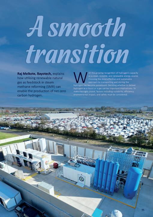

www.globalhydrogenreview.com


Global Publication
The Spring issue of GlobalHydrogenReview is out now Read the issue here Subscribe for free:
Table
1. Key features of plant operations across different autonomy levels1
Level Autonomous plant Control room operation
0 No autonomy: humans carry out all necessary operations without assistance.
Humans carry out control of all assets without assistance. Low-level automation might be available (e.g., safety system).
1 Operations assistance: automation system provides decision support for necessary operations by remote/digital assistance. Humans always responsible.
2 Automation system is in control in certain situations on request (humans pull support, e.g. for plant startup). Humans always responsible.
3 Automation system is in control in certain situations. Plant actively alerts to issues and proposes solutions. Humans confirm or act as a fallback.
4 Autonomous operations in certain situations: automation system has full control in these situations, humans might supervise actions.
5 Autonomous operation in all situations. Humans may be completely absent.
Automation of control loops during steady-state. Manual startup and shutdown of the plant. Manual execution of transitions. Alarm-based notification.
Automation system assisted plant startup, transition, steady-state, and shutdown. Manual fault correction supported by decision support system.
Automated plant shutdown, startup and transition, on human request. Automatic correction of known deviations. Decision support for unexpected/ unknown faults.
Autonomous control in certain situations with automatic fault and deviation correction and avoidance.
Field operation/ maintenance Planning and scheduling
All field operator tasks executed by humans.
Manual development of plans and the corresponding schedule.
Automation system notifies humans about field activities. Some tasks are automated, e.g. operating valves.
System guided field operation tasks. Humans get instructions what to do and when by decision support system.
ERP plan creation on human request. Human decides when and how to execute the plans and adapts plans.
patterns in the operational data and predicting when the same anomaly is likely to reoccur.
Following this example, predictive maintenance solutions are increasingly adopting AI algorithms to reach their goals by exploiting the information gained from smart devices and instrumentation. This aids the efficient designing of maintenance concepts, considering the input from predictive maintenance solutions which allow optimised plans based on autonomous and enhanced condition monitoring of the systems.
Autonomous control, fault correction and avoidance in all situations. No human supervision required.
Most tasks required for standard operations are automated, like shutdown, startup and transition phases. Number of humans in the field heavily reduced.
Adaptations of plans to current situations by operator request.
The CLUE SaaS platform, developed by S.A.T.E., is an example of an advanced predictive diagnostics and prognostic solution, leveraging model-based and AI-based approaches trained on operations data, to provide:
n Early fault detection and assessment of the health status of the monitored assets.
n Fault isolation and support to troubleshooting.
n Prognostics of the monitored assets (prediction of the future health status and remaining useful life).
Continuous feedback and re-planning in case of production deviations. Manual schedule release.
Almost human-free field operation. Only human field operation in exceptional situations. Continuous autonomous planning and scheduling without user interaction. Detection of production deviations and re-planning. Manual schedule release.
Autonomous field operation, no manual actions in the field necessary. No humans remain in the plant.
Autonomous development and execution of plans and schedules. Autonomous re-planning in case of production deviations. No human interaction.
These functionalities are implemented by a set of CLUE kernel modules (KMs):
n Diagnostic kernel modules (DKMs): the goal of these modules is to provide a measure of the health status of a system and its subsystems and trigger alerts in case incipient fault symptoms are detected. These modules help to detect anomalies before they evolve into failures and also help to provide a ranking of the anomalies detected, in order to identify the most critical ones.
n Troubleshooting kernel modules (TKMs): these modules provide information that is useful for anomaly troubleshooting, e.g. possible root causes of anomalies or correlated events, with the goal of accelerating the fault isolation process and the root cause analysis.
n Predictive kernel modules (PKMs): these modules provide
June 2024 HYDROCARBON ENGINEERING 68
BE WISE WHEN YOU ADVERTISE
Everyone wants to get what they paid for. Hydrocarbon Engineering is independently verified by ABC, because we want our advertisers to know they’re getting the exposure they’ve been promised.
ABC. See it. Believe it. Trust it.

www.abc.org.uk
indications of the potential future evolution of the health status of the monitored assets to help operators optimise the maintenance/preventive operations schedule.
The CLUE predictive diagnostic engine also integrates the troubleshooting support module and configuration monitoring module, which are software components that are designed to monitor the kernel modules’ output and provide insights and information useful to the issues investigation, and autonomous monitoring of the system performance to automatically detect where configuration updates may be required. These main building blocks are represented in the diagram reported in Figure 2, showing the high-level architecture of the platform.
CLUE represents one of the main building blocks required to achieve plant autonomy. Following the scheme in Figure 2, CLUE functionalities implement the reasoning step (‘understand’) to enable plant self-monitoring through real-time supervision, self-diagnosis of its component, evaluation and forecasting of its state. The input to the reasoning is the field data, acquired from the sensors and actuators (‘perceive’). The reaction to the detected events
and the planning of mitigation actions or new maintenance plans (‘solve’) need to be implemented by additional project-specific modules, which logics shall take into account the operational procedures, the process constraints and requirements.
Due to its modularity and flexibility at interface level, the CLUE diagnostic engine can be easy integrated in the plant IT infrastructure and interfaced to the plant digital twin, if available. In this case, the input data is retrieved from the plant database (or from the digital twin itself) and the results of the investigation are provided to the digital twin (Figure 3). In this way the results are made available directly in the digital twin, with no need for access to different user interfaces.
CLUE also provides a dedicated, intuitive and operator wise user interface (UI), accessible by browser, where jobs can be scheduled and results investigated. The dashboard and UI panels are designed to provide all the information to allow users to quickly understand the condition of the system and the reasoning performed by CLUE, enabling a quick reaction to events if required.
CLUE can be customised for specific use in different applications. It is already in use in different application domains, such as in the automotive and space industries, where the approach validity and the economic benefits achieved by customers were measured from operational use of these technologies.
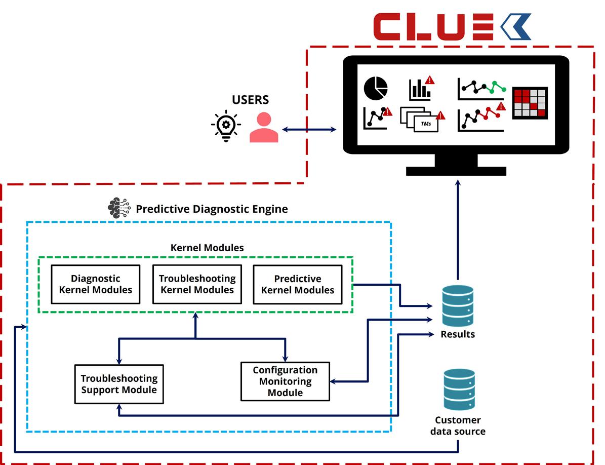
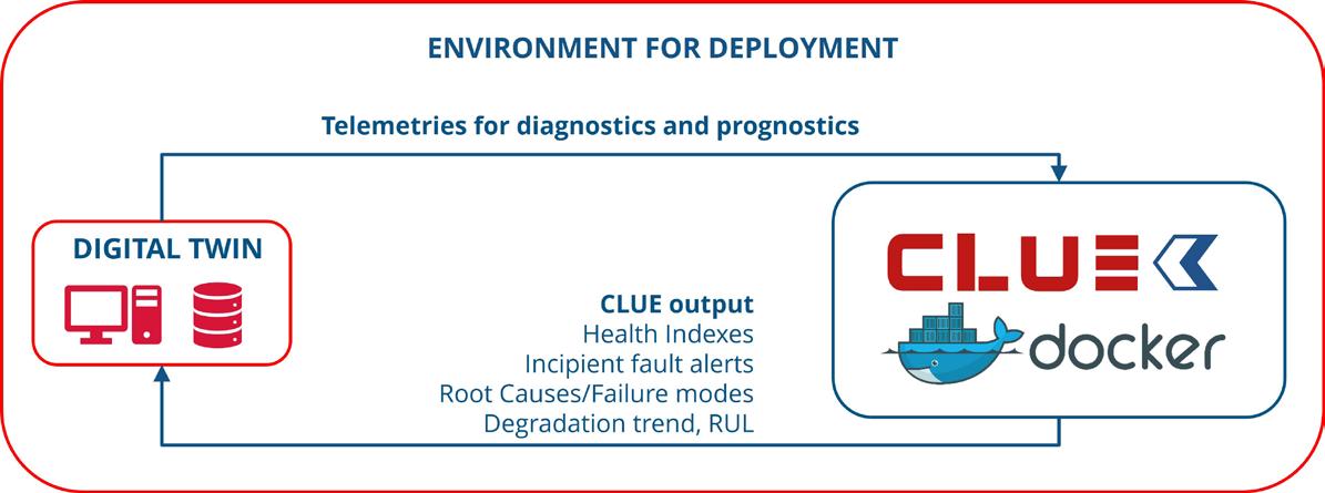
Conclusion
This article has presented a brief overview of the main challenges and implications of increased autonomy in industrial systems and plants. Enabling technologies are essential building blocks to fully autonomous self-diagnosis, recovery and maintenance planning systems.
The path towards the adoption of fully autonomous systems is long-term and shall tackle several issues, including legal and safety aspects. However, a stepwise adoption of modules and building blocks, validated in a semi-autonomous process, will likely bring several advantages which are already in practice. These are expected to include optimisation of human tasks, better handling of increased system complexity, the ability to react in real-time to unexpected events, and higher predictability under verified conditions.
References
1. GAMER, T., HOERNICKE, M., KLOEPPER, B., BAUER, R., and ISAKKSON, A. J., ‘The autonomous industrial plant – future of process engineering, operations and maintenance’, Journal of Process Control 88, 101 - 110, (2020).
2. DEVOLD, H., and FJELLHEIM, R., ‘Artificial Intelligence in Autonomous Operation of Oil and Gas Facilities’, Abu Dhabi International Petroleum Exhibition & Conference, (2019).
3. ‘Digital transformation: powering the oil & gas industry’, Oil & Gas Journal, ogj.com/print/ content/17297879
4. YOUNG, A., and ROGERS, P, ‘A Review of Digital Transformation in Mining’, Mining, Metallurgy & Exploration, 36, 683 – 699, (2019), https://doi. org/10.1007/s42461-019-00103-w
June 2024 HYDROCARBON ENGINEERING 70
Figure 2. CLUE high level building blocks.
Figure 3. CLUE integration with plant digital twin.


June 2024 HYDROCARBON ENGINEERING 71 Keep Updated For more news visit: www.hydrocarbonengineering.com Keep up to date with us to hear the latest downstream oil and gas news HE_Social_Media.indd 1 20/11/2018 14:39 Page Number | Advertiser 69 | ABC 37 | AUMA OBC | Axens OFC & 41 | Baker Hughes IBC | BASF 25 | Boldrocchi 31 | Borsig GmbH IFC | Crystaphase 02 | Eurotecnica 49 | GEA 17 | Halliburton Multi-Chem 59 | Heat Transfer Research, Inc. (HTRI) 53 | Integrated Global Services, Inc. (IGS) 21 | Ketjen 13 | Optimized Gas Treating, Inc. 32, 50, 57, 64, 67, 71 | Palladian Publications 35 | Paratherm 60 | REMBE® GmbH Safety + Control 29 | Rotork 04 | Sabin Metal Corp. 63 | S.A.T.E. 54 | Servomex 07 | Sulzer Chemtech 11 | W. R. Grace & Co. 47 | Zwick Armaturen GmbH AD INDEX


Q&A WITH...
Dr. Matthias Schwab Director of New Business Development & Sustainability, BASF Process Catalysts
Matthias Schwab heads the business development and clean tech portfolio at BASF Process Catalysts. His area of responsibility involves catalysts, adsorbents and novel process technologies in four main areas: Low-Carbon Technologies, Renewable Feedstocks, Chemical Recycling, and Reducing Emissions. BASF Process Catalysts maintains a global partnership approach with leading process licensors to deploy cutting-edge, low-carbon technologies. Matthias holds a PhD degree in Chemistry from the Max-Planck-Institute in Mainz, Germany, and obtained a German-French engineering degree from the Technical University of Dresden and the ECPM in Strasbourg, France (École Européenne de Chimie, Polymères et Matériaux).
01 What role will catalyst solutions play in the energy transition?
We believe catalysts will indeed play a paramount role. Just as the central processing unit (CPU) drives the performance of a computing device, catalysts can be understood as the microchips of a chemical plant, powering precise and efficient chemical conversions. Today, about 80% of the processes in chemical industries require the use of catalysts, and I do not expect this number to decline. For the energy transition, there is an urgent need for new process technologies, and consequently for novel catalytic materials.
02 How can your products support companies looking to decarbonise and optimise their operations?
We offer catalyst and adsorbent solutions in our clean tech portfolio in four categories: Lower Carbon Footprint, Renewable Feedstocks, Recycling, and Reducing Emissions. We also cooperate with major process licensors to deploy our sustainability solutions. For example, our fast-growing SYNSPIRETM catalyst suite offers a complete solution to link green hydrogen to net-zero downstream products, our CircleStarTM catalyst offers a solution for customers looking to valorise ethanol towards sustainable aviation fuel (SAF), and our PuriCycle® portfolio enables the processing of circular plastics streams. Our solutions to abate nitrous oxide emissions allow for the decomposition of laughing gas, which is one of the cheapest and most effective ways for plant operators to immediately lower greenhouse gas emissions. All across our portfolio, we are currently rolling out X3DTM, a revolutionary production technology that lifts the performance of industrial catalysts to an unprecedented level.
03 What role will e-methanol and green ammonia play in the energy transition?
We believe that methanol and ammonia will play a central role as sustainable fuels and energy carriers. For both, the infrastructure for transport, storage and handling is in place and technology is proven.
Still, new technology elements are required: take, for example, the demonstration of an efficient and dynamic
e-methanol process in sync with the onstream time of wind power. Additionally, the new feed made from green hydrogen, and carbon dioxide, will require advanced catalytic solutions, like our SYNSPIRETM Methanol catalysts.
Another element will be the large-scale and efficient cracking of green ammonia back to hydrogen. We have fast-tracked the development of a tailormade commercial offering under the SYNSPIRETM ARC brand and are excited to see these catalysts come into first-ever operation in projects very soon.
04 How does collaboration in the catalyst market benefit customers?
In many of the new areas, it is not the time for competition, but for collaboration, so to jointly de-risk new technologies and bring first projects to lift-off. For a long time, we at BASF have been entertaining strong partnerships with technology providers to provide solutions to our customers. The better the synergy between the partners, the better a catalyst can be integrated into process technology and, as a result, the final product is more attractive for the customer.
Our partnering approach offers various degrees of exclusivity and can be tailored to any type of project and customer need.
05 What does the future hold for industrial catalysis?
It is a great time to be in the industry. With our products, we are at the heart of a generational shift last witnessed when the world transitioned from the coal into the oil era. The new prominent raw materials of the future will be green hydrogen, carbon dioxide and renewables, and their use relies on the rapid adaptation and scaling of new technologies.
Wherever technical challenges need to be overcome, and innovative solutions are required, the BASF team feels at home. Already a century ago, BASF pioneered the industrial synthesis of both ammonia and methanol, and it was done by catalysis. As stated by Nobel laureate, Benjamin List, catalysis “is probably the single most important technology for our future.”
June 2024 HYDROCARBON ENGINEERING 72
Catalysts are the microchips of the chemical industry
Powering the energy transition

Learn more about the sustainability solutions by BASF Process Catalysts
Hello!

SULFUR RECOVERY CATALYSTS
CRS 31 & CRS 41 Promoted TiO₂
CSM 31 Aromatics Guard
AM & AMS Sulfation Guards
CR Series Standard & Optimized Macroporous Aluminas
New
TG 103 & TG 203
Conventional Temperature CoMo Catalysts
TG 107 & TG 136
Low-Temperature CoMo Catalysts
DR Series & ICB Bed Support Media
CR-3S Optimized Ultra-Macroporous Alumina
Click here
