9 minute read
Fight the surge


Nabil Abu-Khader, Compressor Controls Corp. (CCC),
UAE, explains the effect of a proactive recycle trip response in antisurge control.
Compressor Controls Corp. (CCC)’s coordinates for antisurge control take into consideration the reduced flow squared, q2 sr vs the reduced head, hpr or compression ratio, Rc. The distance between the operating point and the surge control line (SCL) of a centrifugal or axial compressor is called the deviation (DEV). Typically, once DEV becomes negative, antisurge controllers

Figure 1. Antisurge control lines within a typical antisurge controller. start to open antisurge valves in order to avoid going into surge. This article discusses the effect of the proactive recycle trip (RT) response, which acts on the antisurge valve even if the DEV is still positive.
The relationship between DEV and proximity to surge (Ss)
The proximity to surge distance is a function of compression ratio, flow rate, rotational speed, guide vane angle, as well as gas pressure, temperature, and composition. To develop the invariant coordinate space, the reduced flow squared, q2 sr is normally used in the X-coordinate. As a CCC rule of thumb, if the gas composition and gas parameters remain reasonably constant, then it is possible to further simplify the Y-coordinate in the invariant coordinate space to be the compression ratio, Rc. But if the gas composition and gas parameters change dramatically, then reduced head, hpr should be used in the Y-coordinate. Within this ‘non-dimensional’ coordinate space, the angular distance between the operating point and the SLL, SS, can be calculated as per equation 1:
SS = SlopeOPL⁄SlopeSLL (1)
Where:
SlopeOPL is the slope of the operating point line in the compressor map, and SlopeSLL is the slope of the surge point line in the compressor map.
The variable Ss is calculated continuously in the antisurge controller. As Ss is < 1 for normal operation, and Ss is > 1 when the system is in surge, this allows for easy judgement of different compressor systems by using the same surge parameter variable. The antisurge controller continuously calculates how much the operating point deviates from SCL using the SS parameter, considering the overall control margin (b). The DEV is typically calculated by using equation 2:
DEV = 1 - SS - b (2)
As a result, the DEV is positive when the operating point is to the right of the SCL. In this case, if the antisurge valve is not fully closed, the antisurge proportional-integral (PI) response should gradually close it. The DEV will have a value of zero on the SCL, and will be negative when the operating point is to the left of the SCL, causing the antisurge valve to open.
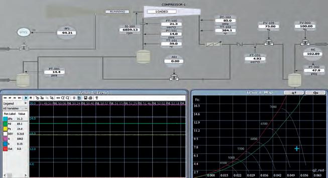
Figure 2. An example of a running standalone compressor train.
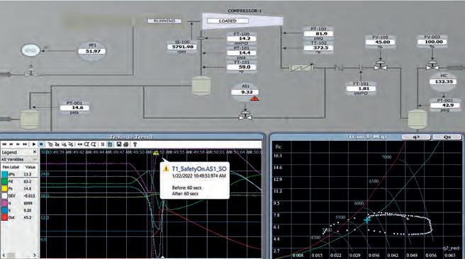
Figure 3. Typical surge cycle as a result of sudden high back pressure.
The antisurge control lines
Typically, the order of the antisurge control lines in a compressor map is – from right to left – SCL, RTL, SLL, and then SOL, as shown in Figure 1. When the operating point of a compressor crosses the SCL, a PI response acts on the antisurge valve.
An improper PI tuning or a higher back pressure (higher resistance) could lead to a large RT action upon crossing the RTL. This is experienced as high disturbance in the process. If the compressor experiences pressure even further back, forcing it to operate to the left of RTL, this could lead to compressor surge.
In its closed-loop response, the antisurge controller will vary its output based on its PI tuning parameters as a first line of defence, and then it may use RT action as a second line of defence if the operating point crosses the RTL. RT action, which is an open-loop response, will produce a relatively larger step opening (and possibly multiple steps) to the antisurge valve, increasing the flow in the compressor.
In most cases, this will cause high process disturbance. The intention of these defence lines is to protect the compressor from surge by manipulating the antisurge valve to move the operating point back to the desired surge control margin. CCC proposes the use of relatively smaller RT steps in response to the variations of DEV before (or even after) the operating point reaches the SCL.
It is important to note that there are many cases where the antisurge valve opens, even if the calculated DEV is positive. These could be being in a process limit condition, receiving a compressor stop or ESD request, or recycle-balancing with other trains in a parallel compressor network. These conditions, among others, override the DEV calculation loop, ‘forcing’ the antisurge valve to open.
The normal RT response, whether there is a derivative action or not, is typically triggered when the operation point crosses RTL. An RT proactive response can be initiated based on the derivative of the proximity-to-surge variable dSs/dt (dSs). When this response is enabled, the antisurge valve will step open by a configured amount (called the RT_dSs_response) when the value of dSs/dt is greater than a configured value (referred to as the RT_dSs_level) for a specified amount of time (called the RT_dSs_delay). If both the normal RT step response and the proactive RT response are triggered simultaneously, the controller will select the larger response and add it to the antisurge valve output.
Simulation results
Figure 2 shows the process to be simulated, with one centrifugal compressor in a standalone configuration.
Bleed area: 216mm x 152mm Trim area: 210mm x 146mm
Safe area: 190mm x 126mm
Half page horizontal artwork guidelines WE’RE IN YOUR INDUSTRY

Bleed area: 216mm x 152mm
• Extend your background to fill the full
‘bleed area’ - it’ll make sure you don’t end up with white edges round your advert when it is printed.
Trim area: 210mm x 146mm
• This is the size your advert appear
Safe area: 190mm x 126mm
• Keep all important bits of your design - text, logo, icons - inside this area. (Not your background - that still needs to run to the edges of the bleed.)
Paratherm has been the premier heat transfer fluids provider in the industry for over 30 years.
We Art work specifications / our preferred format: offer a wide range of heat transfer fluids and services to fit your process. Through • PDF-x/1a. • PDFs generated using Press Settings. providing users an extensive fluid analysis program, we deliver results that matter for your system. Our expert and In addition, please note the following: • PDFs should be compatible with Acrobat 4.0 or higher. knowledgeable technical staff provides superior service alongside our • Please ensure all fonts are embedded. • All original graphics must be saved as CMYK at 300 dpi at the size team of talented specialists and sales engineers dedicated to deliver. It’s what we’re most they are to be used. • Please ensure all PDFs are higher than 144 resolution. proud of. Our commitment to your process is what makes us the right choice for you! • Images should not be tagged with any ICC profiles. We operate a preflight system prior to printing to check that Learn more at Paratherm.com all advertisement material complies with the above specifications. Any advertisement that does not comply with these specifications may need to be resupplied.
The compressor train has its own dedicated antisurge (AS1) and performance (PF1) controllers, which control discharge at a setpoint of 85 psig.
As shown in Figure 3, a sudden increase in process resistance (by closing the discharge valve [FV-105] from 75% down to 45%) caused the compressor to enter into a surge cycle (safety on condition) due to high back pressure. Both SCL and RTL acted on the antisurge valve (red trend), but this could not prevent surge in the compressor. The antisurge valve opened by more than 45% during the surge cycle, causing high process disturbance. This section will now go on to discuss how to rectify the flow in the compressor, and then activate an RT proactive response.
Inducing a proactive RT response
As shown in Figure 4, closing FV-105 once more from 75% down to 45% caused the operating point of the compressor to move to the left of the compressor map. The RT proactive response was activated, causing the antisurge valve to open before the operating point reached SCL. As a result, the compressor did not go into surge, and less process disturbance was witnessed. A couple of RT proactive steps were observed on the antisurge valve output (the red trend).
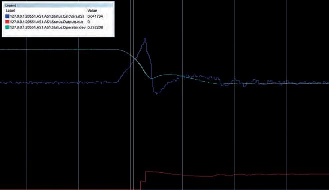
To further analyse results, and to determine the dSs settings at which an appropriate proactive RT step should take place, CCC used the Fast Recorder programme. This enabled the company to capture the variations of dSs, DEV, and antisurge valve output. The history of the compressor surge events (if available) could also be used to determine the appropriate settings.
The proactive RT configuration parameters used in simulation are: n RT_dSs_delay = 0.2 sec. n RT_dSs_enable = true. n RT_dSs_level = 0.04. n RT_dSs_response = 5.
It is important to note that increasing the RT_dSs_response value could lead to an unstable and oscillatory process. As shown in Figure 5, the proactive RT response was activated right after the dSs value reached RT_dSs_level = 0.04, as expected, even before reaching the SCL (the blue trend). After the first proactive RT step, and as the DEV is still positive, the controller attempted to close the antisurge valve. As the dSs value remained greater than RT_dSs_level for more than RT_dSs_delay = 0.2 sec., another proactive RT step was observed (the red trend). After the second step, the dSs value became less than the RT_dSs_level. As such, no additional steps were added. As a result of the increased flow in the compressor, and because the DEV remained positive, the antisurge controller slightly closed the antisurge valve very slowly, settling the operating point on the SCL.
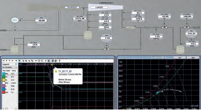
Figure 4. Inducing a proactive RT response to the right of the SCL. Figure 5. Fast recorder trends for the proactive RT response.
Conclusion
With a properly tuned proactive RT response, companies can operate both the centrifugal and axial compressors safely and away from surge. This technique also results in minimised process disturbance during sudden high back pressure situations. Caution should be taken when using this feature, as improper tuning could result in an unstable process. The use of the antisurge control lines shown in Figure 1 is still required for compressor protection from surge. These lines are required in order to absorb higher disturbances that the proactive RT response cannot handle.