
8 minute read
Control valve selection for ethylene plants


Mark Wagner, Emerson Automation Solutions, USA,
explains why choosing the right combination of valve style, trim type, materials of construction, and digital positioner is critical for profitable operations.
Ethylene is one of the most mass-produced petrochemicals in the world. It is typically formed by steam cracking naptha or natural gas liquids, and once isolated and refined, it is sold as an intermediate to feed a wide variety of petrochemical processes. Most of the ethylene produced is used in various forms of plastics, but the hydrocarbon is also used to produce specialty chemical products, including antifreeze, insulation, adhesives, paints, and more. There are five major licensors of ethylene plants, but the overall process is similar among designs, and all are very dependent upon control valves in order to operate efficiently and reliably. This article will focus on the critical valves throughout the ethylene process and highlight key selection criteria necessary to ensure consistent and reliable performance.
The ethylene process
The ethylene plant can be divided into the front end ‘warm section’ and a back end ‘cold section’ (see Figure 1). The warm section starts with a cracking furnace where naptha or natural gas is mixed with steam in a very specific ratio, with the mixture then subjected to very high temperatures. This fractures the hydrocarbon into a number of components (ethylene, propylene, acetylene, etc). The gas is quickly quenched to stop
the reactions. It is then compressed, and finally run through various vessels to remove acids and water.
The product stream is then chilled and routed through a series of distillation columns to isolate the ethylene from other hydrocarbons formed in the cracking furnace. These towers remove methane, ethane, acetylene, propane, propylene, and other heavy constituents.
Figure 2 shows an overview of the specific process vessels used in an ethylene plant, with the critical control valves highlighted. These valves must endure a variety of difficult process conditions, so each must be specified carefully.
Critical control valves in the warm section
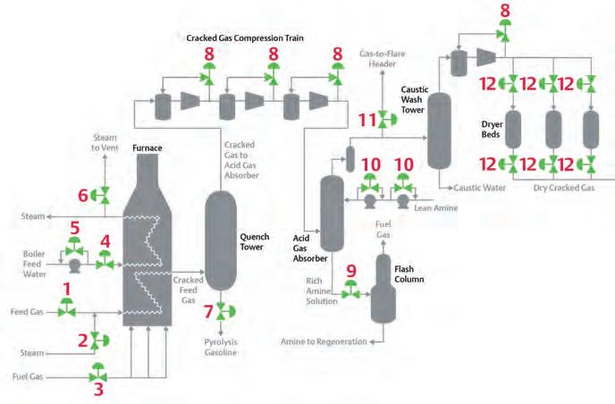
Figure 3 focuses on the front end of the ethylene process, which begins with the cracking furnace. The furnace must be carefully controlled, or the process can become plugged with coke deposits, forcing an extended shutdown. The three major control valves in this area are the hydrocarbon feed valve (#1), the dilution steam ratio valve (#2), and the burner fuel control valve (#3).
Each of these valves must provide very tight flow control, so high-performance globe valves with diagnostic positioners are the norm. Any valve in hydrocarbon service will also require some form of environmental packing to minimise emissions. The steam valve may employ environmental graphite packing to minimise friction and handle the high temperatures.
The next major process area is the quench tower. Here, the very hot gases from the furnace are quickly cooled to stop the reaction process and avoid the production of unwanted side products. The most critical valve here is the quench tower level valve (#7). If naptha is the feedstock, then oil is often used as the heat transfer fluid in this tower, and it tends to fill with carbon particles. This subjects the valve to a very erosive slurry – a punishing application. Hardened trims, such as Alloy 6 or ceramics, as well as sealed metal bearings, are used to protect the valve internals and lengthen service life. Environmental packing is still required, and most operating units employ diagnostic positioners to sense and indicate developing problems well in advance of failure.
As the gas leaves the quench tower, it must be compressed to raise the pressure for the next processing stages. Each compressor stage depends upon the antisurge valve (#8) to protect the equipment from catastrophic damage during low gas flow. These types of valves are usually very large as they must carry at least the full compressor capacity, while enduring very high pressure drops and flow rates.
They must also move very quickly and precisely to arrest compressor surge conditions when they occur. These control valves are customised with pneumatic boosters, actuators, and very high speed and precision positioners to meet the required performance specifications. They can also be specified with specialised trims and diagnostic positioners for performing online partial stroke testing without process upset.
After compression, the process gas enters the acid gas absorber, which circulates an amine solution to absorb acidic gases so they do not create process problems downstream. The most critical valve in this section is the rich amine letdown control valve at the bottom of the acid gas absorber (#9 in Figure 3). This valve is subjected to high pressure drop by design so that the entrained acidic gases separate from the rich amine solution, allowing it to be recycled. This type of separation is known as out-gassing, and it generates noise, vibration and erosion. The internals of this valve must employ hardened trim materials, as well as some type of anti-cavitation trim, to minimise damage and lengthen maintenance cycles. Environmental
Figure 1. The ethylene process starts with a cracking furnace to create the ethylene, and then progresses through a series of steps to remove acids and water, and to isolate the ethylene.
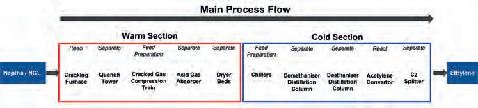
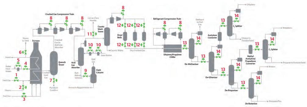
Figure 2. This process flow diagram shows the major vessels and critical control valves associated with a typical ethylene plant.
packing is required, and a diagnostic positioner is a good choice to detect and alarm as the valve develops the inevitable trim damage associated with this very difficult service.
After leaving the acid gas absorber and caustic wash tower, the process gas enters the drying section, where all traces of water must be removed. Drying technologies vary, but usually the process involves multiple molecular sieve beds which are alternately switched in service to dry the gas, or switched offline to be regenerated. The dryer switching valves (#12 in Figure 3) are very critical to the process and must endure challenging process conditions.
These valves are constantly switched open and closed, and despite large temperature swings and reverse pressure service, each valve must provide virtually zero leakage. The best valve design will depend on the specific application but will usually require quickly stroking double eccentric ball valves or high-performance triple offset valves. Diagnostic positioners in this service can detect developing valve problems well in advance of failure to avoid unplanned dryer outages.
Figure 3. This flow diagram focuses on the front end ‘warm section’ of the ethylene process. The major vessels include the cracking furnace, quench tower, cracked gas compressors, acid removal section, and dryer beds.
Critical cold section control valves
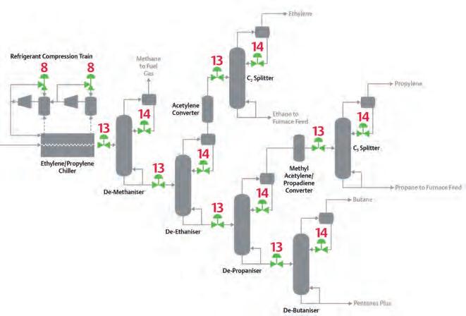
Figure 4 focuses on the back end of the ethylene process, which begins with refrigeration and then runs through a series of distillation columns to separate the process gases into a variety of purified products. Very precise flow control is critical
Need a reprint?


We can tailor to your requirements, produce 1 - 12 page formats, print colour or mono and more
Conclusion
for distillation column operation, so extremely accurate and consistent flow control is paramount in this section of the plant.
The major valves in the distillation section for each column include the distillation feed control valve (#13) and distillation reflux control valve (#14). The initial columns in this process tend to run at cryogenic temperatures, so control valve trim and soft parts must be selected to handle those conditions. This
section of the plant tends to have extended runs with few shutdowns, so it is imperative that reliable, long-lasting valves are chosen. Each control valve must be carefully sized to provide consistent and stable control, and the valves themselves are usually high-performing globe valves with diagnostic positioners and environmental packing. The ethylene process poses a wide range of service conditions for control valve selection, and each application must be carefully evaluated to ensure the proper valve body style, trim, actuator, packing and positioner are selected to provide reliable and long-lasting performance. Figure 4. This flow diagram focuses on the back end ‘cold section’ of the Unexpected valve failures and process ethylene process. Ethylene is refrigerated to very low temperatures and shutdowns are extremely costly, so digital then passed through a series of distillation columns to separate and purify the process streams. positioners with the ability to detect and alarm developing problems are often employed, as they usually pay for themselves in a very short time by reducing unplanned downtime. The number of available design options are extensive, so end users may find it helpful to consult with valve vendors to determine the best valve type, packing, materials of construction, and digital positioner for their specific application.
AD INDEX

Page Number | Advertiser 27 | Ariel Corp. 21 | Aspen Aerogels, Inc. 53 | AUMA 24 | Borsig GmbH
OFC & 41 | Elliott Group 02 | Eurotecnica 30 | HTAC | HGT 42 | hte GmbH 29 | Intertek 33 | MOGAS Industries, Inc. 45 | NEO Monitors 17 | NEUMAN & ESSER
23
| Nikkiso Clean Energy & Industrial Gases AGroup 35 | Optimized Gas Treating, Inc. OBC | Owens Corning 63, 64 & 71 | Palladian Publications 49 | Paratherm 11 | Rotoflow, an Air Products business 57 | S.A.T.E. 07 | SBW Group 15 | Solar Turbines, a Caterpillar Company 58 | Sulphur + Sulphuric Acid 2022 04 | Sulzer Chemtech 67 | Turbomachinery and Pump Symposia 18 | ValvTechnologies IFC | Vympel GmbH IBC | W.R. Grace & Co.


