
10 minute read
Leading the way towards LNG safety


Alec Cusick, Owens Corning, USA,
details a passive approach to mitigating pool fire risk at LNG facilities.
The risks of a spill or fire occurring are continuous for facilities that work with or store combustible materials such as hydrocarbons and LNG. Having flammable liquids onsite means that the potential for spills and fires is always present, posing a risk to facility employees, equipment and neighbouring areas. These concerns have led to the formation of regulations and organisations that are focused on site safety, including the US Federal Energy Regulatory Commission (FERC), the Pipeline and Hazardous Materials Safety Administration (PHMSA), and the National Fire Protection Association’s standard 59A – Standard for the Production, Storage and Handling of Liquefied Natural Gas (LNG).1 By preparing for the occurrence of a spill, and having safety measures designed and installed – such as a passive spill and fire response system – safety and facility teams can help mitigate some of the risks involved in managing LNG plants.
Priorities during LNG spills
When planning mitigation strategies for spills of LNG or other hydrocarbons, there are some key objectives that should be prioritised to help avoid potential disaster. These include reducing vaporisation of spilled liquid hydrocarbons and limiting the radiant heat of any fires that occur.
Should LNG or another flammable cryogenic liquid spill, the material will heat as it is exposed to the comparatively-warmer ground and air, along with solar radiation. As material warms it releases invisible, flammable vapours which can ignite when combined with a spark. Because the gas is only flammable at certain concentrations (approximately 5 – 15%), it can travel downwind before igniting. However, as the flammable gas that is generated can also catch fire over the spill pool, reducing the rate of vaporisation fits together with another priority – limiting thermal flux.
If a fire occurs following a spill, this becomes the most significant source of heat gain for the spilled material, which increases the rate of vaporisation. Limiting heat gain back into the spilled liquid helps reduce how much fuel is available to burn. When the fire is located over the spill pit, it can allow for a self-propagating cycle to perpetuate as the fire feeds heat into the liquid. This creates more flammable gas which, in turn, feeds the fire.
Standards have been established to address safety onsite and in neighbouring locations. One example is the National Fire Protection Association’s 59A, the Standard for the Production, Storage, and Handling of LNG.1 This standard can be used to establish requirements for exclusion zones around a facility, and inform site layout. Addressing regulatory requirements can be difficult and expensive when facilities have small site footprints, or when they try to expand without adding an external area. While this standard could potentially be cited as grounds for denying regulatory approval of a facility, it does account for the use of passive fire mitigation methods installed when determining how much of an exclusion area is needed. Final approval will be subject to the agency that has jurisdiction on the location.
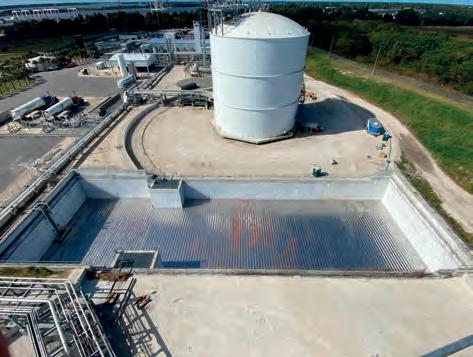
Figure 1. Passive response systems remain in place, ready to self-deploy in the event of an LNG spill.
Mitigation system considerations
Should a spill and/or fire occur at an LNG or hydrocarbon storage and processing facility, there are several types of active and passive response systems that can be deployed. An appealing aspect of a passive response system is that there is no delay in its deployment, and no human or mechanical action is required to activate it. Once installed, a passive response system is intended to remain in place long-term, with minimal maintenance. Active systems, such as fire-extinguishing foams, need to be triggered in an emergency prior to activation, potentially by sensors or an employee. Additionally, many active systems may require higher levels of regular maintenance, much like a fire extinguisher needs to be checked for charge and function, and may need to be refilled or replaced. Often, passive and active response systems can be integrated, providing a combined response should a spill occur.
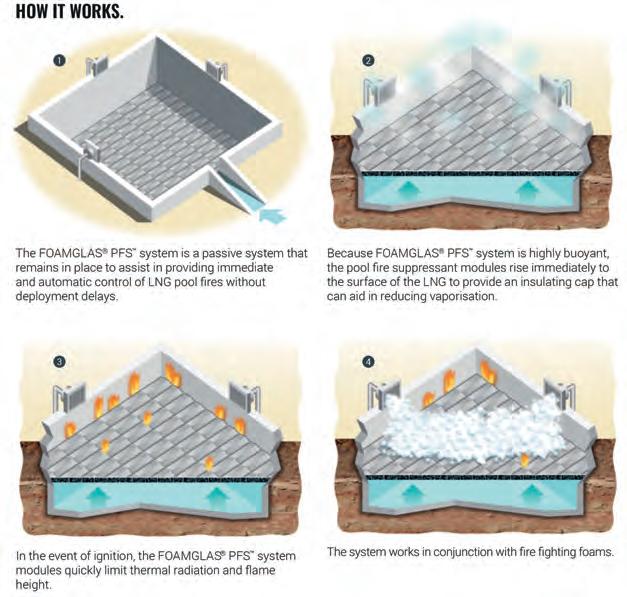
Figure 2. In the event of a pool fire, the passive pool fire suppression system works as a single unit to reduce radiant heat and flame height.
Implementing a passive response system
A passive response system has been designed that is specifically focused on limiting radiant heat and flame height in the event of a spill and/or fire occurring. The patented system – FOAMGLAS® Pool Fire Suppressant (PFSTM) Gen 2 – is designed to
rest within a spill pool and wait until a spill occurs before self-deploying. In the event of a spill, the system creates a non-combustible insulating cap that floats to the top of the spilled, flammable liquid, creating a barrier between the liquid and solar radiation or other heat sources.
The system is comprised of a series of individual blocks of cellular glass insulation wrapped in a silicone adhesive coating and cladded in stainless steel. Once in place, the blocks are linked together using a series of metal bridges, allowing the individual elements to work as a single unit. The system is customised to meet the dimensions of individual spill pits; however, it is easy to install.
The passive safety system makes use of the unique properties of cellular glass insulation. An inorganic substance, the material does not burn, spread fire, or generate smoke, and it is non-combustible. The insulation is also impermeable and non-absorbent when exposed to liquids – including hydrocarbons.
Should a fire occur over the spill pit, the insulating blocks have been found to help protect the spilled liquid from the heat that has been generated, reducing vaporisation and flame height.2 Flames also pose a danger to nearby piping and equipment, especially in sites with limited space. As temperatures increase, piping that contains LNG or a similar liquid runs the risk of exploding when the liquid heats and expands into a gas. Additionally, structural steel can begin to lose its strength from rapidly increasing temperatures, upon reaching about 315.56°C (600°F), and loses approximately 50% of its load bearing capacity when heated to 593.3°C (1100°F).3 This has the potential to add additional fuel to the fire if the structural elements that have been damaged are supporting spheres or other storage tanks holding volatile materials.
An insulating layer in place at the top of the spill pit helps to reduce flame height and radiant heat flux. Additionally, the floating response system can be paired with other active safety measures, including fire-suppression foams.
System testing was completed by Resource Protection International (RPI) on behalf of Total Oil Co. at Centro Jovellanos in Asturias, Spain.2 The examination checked for the effectiveness of vapour control and reduction in heat flux. A 4 m2 containment pit equipped with a series of radiometers at each corner was flooded with 1.5 m3 of LNG and ignited. The pit was allowed to burn for 30 minutes, and then extinguished. The heat flux ranged from 3 to 8 kW/m2. After the passive safety system was added to the pit, it was refilled and reignited. With the cap in place, thermal flux was measured below 1 kW/m2 . Additionally (although this is an atypical practice), upon conclusion of the test, the pit fire was controlled enough to be extinguished by a person in the correct personal protective equipment (PPE) walking up to the edge of the pit and using a dry chemical spray.
To look at the response provided in terms of the reduction in vaporisation, consider the following scenario: a containment pit measures 4.57 m x 4.57 m x 3.05 m (15 ft x 15 ft x 10 ft) with 15 cm (6 in.) concrete walls; a ground temperature of 20°C (68°F); an air temperature of 24°C (75°F); spilled LNG at -160°C (-256°F); and a heat of vaporisation of 512 kJ/kg (220 Btu/lb). In an unprotected pit, total heat gain is 32.5 kW (31 Btu/sec.) and the boil off is 3.81 kg/min (8.4 lb/min). However, if an insulating cap is in place on top of the spilled LNG then the total heat gain falls to 9.04 kW (8.6 Btu/sec.) with a boil-off rate of 1.06 kg/min (2.34 lb/min). This amounts to approximately a 72.2% reduction in heat gain and boil off, limiting the amount of fuel for a potential fire.4
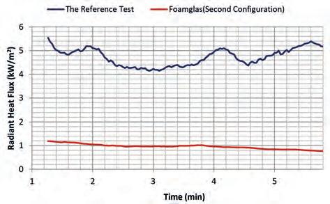
Figure 3. The difference in measured radiant heat flux from the capped (lower) and open (upper) spill pits.
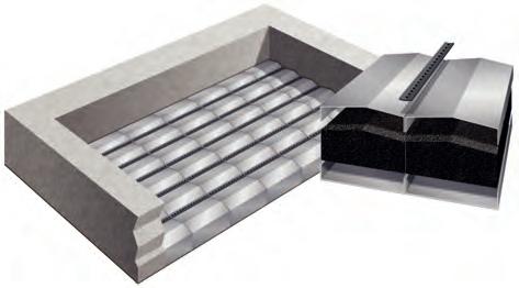
Figure 4. Individual blocks are connected to create the floating cap.
Case study – the JAX LNG facility
Passive safety systems such as the FOAMGLAS PFS Gen 1 and Gen 2 have been installed across a range of facilities around the globe, including in Barbados, Singapore, France, Australia, Korea and the UAE. Additionally, a system was recently selected and installed for the JAX LNG facility near Jacksonville, Florida, US.
Opened in 2018, the facility has an onsite LNG storage capacity of 7.6 million l (2 million gal.), and a liquefaction capacity of 454 000 l/d (120 000 gal./d), both of which will increase when Phase II is completed later in 2022. The facility is a joint venture (JV) between Pivotal LNG – a BHE GT&S company – and NorthStar Midstream.
The combination of the facility’s small site size and expanding storage and production led to regulatory considerations in the event of a spill and/or fire. To help mitigate these concerns, a passive safety system in the form
of the PFS Gen 2 system was added to a large spill containment pit onsite.
“The end goal of having the safety system in place is never to use it,” said John Morrison, LNG facilities Maintenance Coordinator at JAX LNG. “The installed system functioned well – we liked what we saw with the test,” he added.
To install the passive safety system, measurements were taken of the spill pit, and a design of how best to fill the space given the dimensions and obstructions – such as ladders or pipes – was determined. All of the coated and covered insulation blocks were shipped to the site, ready to be installed using the provided bridging and connection materials. On the edges of the system, metal flashing was added to help reduce gaps between the edge of the blocks and the pit wall.
Sometimes a system has the opportunity to demonstrate its usefulness before it is actually required to perform. Although unintentional, installers at JAX LNG saw how well the system floated early in the installation process. When only a few rows of the blocks had been moved to the pit and connected, heavy rains left standing water in the space, which lifted and moved the blocks, providing a minor demonstration of how the whole system is designed to work in the event of an emergency.
Once the entire series of blocks is installed, there is far less room for block movement other than up and down. The system is low maintenance, but it is encouraged that standing water should not remain in the spill pit and any debris that falls on top of the buoyant cap should be removed. At JAX LNG, the passive system was complemented by a foam suppression system.

Conclusion
The goal of having emergency measures in place to address a spill is to never need them. However, the handling and storage of flammable liquids means that spills and fire risk must always be considered. Having passive fire mitigation systems in place provides a long-term, always-ready response if a spill should occur. Using a system such as the FOAMGLAS PFS System Gen 2 helps to address the priorities created during an emergency by rising to the top of any spilled LNG and insulating it from external heat sources. This passive approach helps to reduce the rate of vaporisation, and limits thermal flux and flame height in the event of a fire, helping to address facility safety.
References
1. ‘Standard for the production, storage, and handling of liquified natural gas’, National Fire Protection Association (2019), (NFPA 59A – 2019), retrieved from https://www.nfpa. org/codes-and-standards/all-codes-and-standards/list-ofcodes-and-standards/detail?code=59A 2. ‘Vapor & Fire Control Testing of FOAMGLAS® PFS System (Gen 2) on LNG’, Resource Protection International, (2014). 3. Steel Solutions Center. (2022). 11.2 Steel Exposed to Fire.
American Institute of Steel Construction (AISC), https://www. aisc.org/steel-solutions-center/engineering-faqs/11.2.-steelexposed-to-fire/#9370 4. Internal trials and calculations (2014).
SulphurPro®
Native Sulphur
The ULTIMATE in Sulphur Plant Simulation
Optimized Gas Treating, Inc
212 Cimarron Park Loop, Buda, TX 78610 www.ogtrt.com +1 512 312 9424


