14 minute read
Keeping your options open


Klaus Brun, Elliott Group, USA, explores the different technology options for hydrogen compression.
The hydrogen economy is a critical part of the trend toward the decarbonisation of the energy sector. Major energy infrastructure changes are required to meet the production, transportation, storage and usage needs for a functioning hydrogen economy. This includes the need to develop compressors that are very different from the types currently used. For hydrogen to be a viable energy carrier, compressors must operate efficiently and reliably. Most importantly, they must be economically-viable.
Hydrogen compression
The compression applications in the hydrogen value stream depend on the type of hydrogen. Specifically, green hydrogen from renewable energy sources is mostly produced at low pressures using electrolysis, and must be compressed, whereas grey/blue/black hydrogen often exits the production process at elevated pressures and requires less compression in order to enter into the pipeline transportation stream. In the near and mid-term future, for economic reasons, it is unlikely that green hydrogen will be a significant contributor to the hydrogen economy or the initial transport, storage and distribution infrastructure. Usage infrastructure will likely rely on blue or grey hydrogen from fossil fuel source conversion. This assumption defines and limits the operating conditions for hydrogen transport to pressure levels/ratios required by pipeline and storage operations, which tend to be between 1000 – 2000 psig, with a compression ratio of 1.5 – 3.0, respectively.
Different types of commercially-available compressors can be used for industrial hydrogen compression. However, the requirement for rugged and reliable operation with large volume flows realistically limits the selection to centrifugal compressors for most pipeline transport applications. Centrifugal compressors have been used for decades for hydrogen compression, albeit for vastly different applications – mostly in the downstream refinery processes.

Compression thermodynamics
There are several common metrics that are indicative of a compressor’s ability to perform a desired duty: n The compression ratio or pressure increase. n The enthalpy difference across the machine (head), which is basically the fluid energy rise per unit mass across the machine. n The comparison of secondary performance parameters such as shaft power required or isentropic/polytropic efficiencies, which relate work input to hydraulic work.
Euler’s turbomachinery equation determines a centrifugal compressor’s head or enthalpy difference, measured in energy per unit mass. It relates aerodynamics (velocity vectors) to thermodynamics (head and power). In its simplest form, Euler’s equation states that the head rise in a compressor is proportional to the angular velocity squared, multiplied by the tip radius squared of the
compressor (assuming radial blades and no slip). It should be noted that there are no fluid properties such as density or viscosity in this equation. This means that the theoretical head rise of a compressor is identical for a light gas such as hydrogen, and a heavy gas such as carbon dioxide. Specifically, for a given centrifugal compressor geometry running at a fixed speed, the head rise of the machine is identical if the compressor runs on hydrogen or any other gas. The energy input per unit mass into these gases is independent of their density or specific gravity. However, light gases, by definition, have low densities, and therefore the energy input for a lighter gas per unit volume or volume flow (e.g. ACFM) is much lower in any compressor.
Pressure ratio can be related to temperature via the isentropic relationships, and temperature is related to head by the definition of enthalpy (specific heat multiplied by absolute temperature). It can be shown algebraically that the most important explicit fluid property that thermodynamically (inversely) relates pressure ratio to head is the specific heat. The isentropic coefficient also relates head to pressure ratio, but is a weaker function. This is the fundamental difference between compression effectiveness of hydrogen vs heavy gas in centrifugal compressors. Hydrogen has a high specific heat value which results in low compression ratios. For example, the specific heat of hydrogen at room temperature is about six times higher than that of methane, which when plugged back into the isentropic relationships results in a pressure ratio several hundred times higher for methane than for hydrogen (assuming the same head from Euler’s equation). Since pressure increase is a simple function of pressure ratio, light gases result in low pressure increases in centrifugal compressors.
The limit of head production in a centrifugal compressor is the mechanical limit of impeller tip speed, as well as the speed of sound of the compressed gas. The speed of sound in hydrogen is about three times higher than for methane. Therefore, if material limits can be overcome to allow for higher tip speeds, each impeller stage can produce significantly higher head per stage than current machines – in theory.
An equation of state of the gas can determine volume ratio, density ratio, and volume reduction across a centrifugal compressor based on the suction and discharge conditions, which behave somewhat linearly with the pressure ratio. This provides reciprocating compressors with a slight advantage. Since they are positive displacement machines, their volume ratio across the machine is determined by the piston stroke volume displacement in the cylinder, which is driven purely by geometry. Although reciprocating compressors require fewer compression stages and can achieve high compression ratios with small machines for light gases, they are flow limited by the cylinder geometry and valve flow choking, and their specific compression power is similar to that of a centrifugal compressor. It is very important to emphasise that the power consumption per mass of gas (i.e. the head) required for a given pressure ratio is independent of the compressor type and method (except, to a small degree, for a possible difference in efficiency). In other words, a reciprocating compressor does not reduce the fundamental power consumption for hydrogen compression of a given mass flow.
Finally, a basic aerodynamic blade design can determine the efficiency of a compressor, and can be optimised for any type of gas. As such, there is no reason that a centrifugal compressor cannot be designed to operate efficiently for a light gas. This has been demonstrated by hundreds of centrifugal compressors that operate efficiently in hydrogen service and, more specifically, in petrochemical and refinery applications. There are many other operational reasons that a centrifugal compressor is preferable for hydrogen compression, such as the avoidance of process gas contamination with lube oil, reduced environmental leakage, no piping pulsation or vibrations, and lower overall maintenance costs. Most hydrogen compression services can be achieved using either centrifugal or reciprocating compressors. Centrifugal compressors are head limited and may require many stages and cases in a series for higher
Table 1. Hydrogen compression applications and expected typical pressure ratios Hydrogen compression applications Pressure (psi/bar) Expected typical pressure ratios
Pipeline recompression 1400/96.5 1.2 – 1.5 Header station (electrolyser, steam reformer, gasifier) to pipeline pressure or liquids plant - 2.0 – 6.0
Fuel supply to power plant:
- Gas turbine combustor pressure from reformer 500+/34.5+ 1.5 – 3.0 - Storage tank pressure 7000 – 14 000/843 – 965 10+
Table 2. High-speed vs low-speed compressors Compressors Tip speed impellers Pressure ratio No. of impellers
Conventional compressor: 1200 fps - Electrolyser to pipeline 2.5 40 (4 – 5 casings) - Pipeline recompression 1.3 8 (1 – 2 casings) - CGT fuel gas compression 2.0 30 (3 – 4 casings) High-speed compressor: 2400 fps - Electrolyser to pipeline 2.5 10 impellers (2 casings) - Pipeline recompression 1.3 2 impellers (1 casing) - CGT fuel gas compression 2.0 8 (2 casings)
pressure ratios, while reciprocating compressors are flow limited and will require many cylinders or compressors in parallel. The choice between centrifugal and reciprocating compressors requires consideration not only of pressure/flow conditions, but also operating economics such as maintenance, reliability, and availability.
Compression applications
When designing the infrastructure for the hydrogen economy, there are several obvious compression application duties. Table 1 shows the most important items with their expected pressure ratio range. Depending on the size of the hydrogen-producing source, the flow rate of these applications can vary widely.
From Table 1, it is clear that most high-volume hydrogen compression applications fall into a pressure ratio range between 2.0 – 3.0. The types of compressors usually considered for hydrogen are reciprocating, screw, centrifugal barrel, centrifugal horizontally split, and integrally geared. Since both reciprocating and screw compressors are severely flow limited, they cannot be practically used for large-scale hydrogen applications. The remaining technology options all rely on proven centrifugal compressors, but use different layouts and stage arrangements. The focus here will be on centrifugal barrel compression since it shows the highest potential for large industrial-scale, reliable, and low-cost hydrogen compression.
The physical properties and flammability of hydrogen poses special technical challenges for centrifugal compressors in hydrogen compression applications. Although hydrogen is processed in many industrial applications, most hydrogen compressors are found in refineries for hydrotreating, hydrogen plants, and hydrocracker applications. Within these refinery applications, feed gas, recycle, net gas, and booster compressors compress hydrogen over a wide range of pressures and flows. Other hydrogen compressors are found in gasification, electrolysis, and many chemical and petrochemical plants.
Compressing hydrogen presents four major technical challenges: n It is an extremely light gas. n It can cause hydrogen embrittlement in ferrous alloys. n Hydrogen molecules are very small, making sealing and containment difficult. n There are safety issues because of its explosivity, low auto-ignition temperature, and wide flammability range.
Light or low molecular weight gases are difficult to compress, and result in a low head rise per centrifugal stage in the compressor. Even at relatively high impeller tip speeds of 350 m/sec., typical pressure ratios per stage seldom exceed 1:1. For rotordynamic reasons, there are finite limits to shaft length in any compressor. Centrifugal compressors can mechanically fit a limited number of stages per casing – usually no more than 10 – 12. Additionally, the impeller and shaft material must have sufficient strength while being light enough to minimise hoop stresses at high rotational speeds.
For example, Table 2 shows a comparison of the number of impellers and cases required for the previously discussed application case (in Table 1) for conventional compressors with tip speeds of around 1200 fps vs novel, high-speed impellers operating at twice this speed.
Theoretically, impellers with very high tip speeds above 2000 fps are possible by using non-metallic materials, magnetic or gas bearings, and special seals. Shaft and impeller material can include titanium alloys, continuously-wound carbon fibre, and ceramics. For example, a continuously-wound carbon fibre shaft has high torsional strength and a quarter of the density when compared to a steel shaft. Similarly, Figure 1 shows a novel, high-speed compressor impeller made from light, high-strength, directionally-wound carbon fibres that has the potential to operate at tip speeds exceeding 2000 fps.
To summarise, the greatest challenges for high-speed hydrogen compression are: n The need to utilise materials that are not commonly used for turbomachinery. n The design of impellers that can handle very high hoop stresses. n The utilisation of seals and bearings at speeds where they have limited operational experience. n The use of high-speed drivers and gears for speeds beyond 50 000 rpm.
Unfortunately, most of this technology is currently in the development stage, and is not practical for rugged industrial applications that require very high reliability, such as pipeline or storage service. There are some critical research gaps that must be addressed before this technology can be applied commercially. More conventional compression technologies will have to be utilised, as this technology is not ready to be deployed on an industrial scale in the foreseeable future. As a result, with currently-available impeller technology, long compression trains with many stages per casing are required if a significant hydrogen pressure rise is needed.
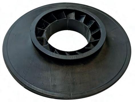
Figure 1. Directionally-wound carbon fibre compressor impeller.
Hydrogen embrittlement is a metallurgical interaction between ferrous metals and hydrogen gas at certain pressures and temperatures that can lead to rapid yield strength deterioration of the base metal in the compressor. In order to prevent hydrogen embrittlement, API specification 617 limits materials in the hydrogen gas service to those with a yield strength less than 120 ksi or a hardness of less than 34 HRC. This material yield strength limits the maximum allowable speed of a given impeller. As noted, this issue can be addressed with high-head impellers, and by using alternative materials with higher strength-to-density ratios – but these technologies are not yet mature. Additionally, special surface coatings are available to minimise exposure and direct penetration of hydrogen into the metal as shown in Figure 2. However, as a safety precaution, current design practices limit the design yield strength of the exposed alloys to below 827 MPa. This further limits the operating speed of the compressor and its pressure rise per stage.
Finally, hydrogen molecules are small compared to most hydrocarbon gases, which makes casing end and inter-stage sealing challenging. Most hydrogen compressors utilise tandem dynamic dry gas seals and multiple static O-rings to minimise leakage flows. Nonetheless, hydrogen detection and scavenging is often required to minimise the risk of hydrogen exposure to the atmosphere and the associated explosive hazards.
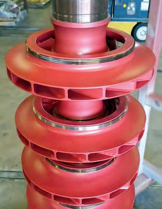
Figure 2. Specialty Pos-e-Coat® hydrogen compressor coating developed by Elliott.
Elliott developed the Flex-Op® compression arrangement to improve the head, flow, reliability, and operational flexibility capabilities of hydrogen compressors, as shown in Figure 3. This arrangement is comprised of four compressors on a single gearbox. This was originally designed for high-pressure ratio and high-flow compression, however, this arrangement has the flexibility to allow individual compressors to run in series or parallel (or both). As previously noted, hydrogen compression requires a large number of compression stages to achieve a reasonable head. With up to four casings, more than 40 impeller stages can fit into a linear footprint that traditionally only fits 10. This shrinks the linear footprint of the compressor section from upwards of 40 ft to roughly 10 ft. Flex-Op can utilise the four compressor casings in parallel or series, with multiple extractions and side streams. As each rotor is connected to its own pinion via a flexible shaft coupled to the central gear, the rotor speeds can be individually-optimised for the highest aerodynamic efficiency. A barrel casing coupled with a single, multi-pinion gearbox allows the whole assembly to be powered by an electric motor with a variable frequency drive, a variable speed drive motor, a Figure 3. Flex-Op compressor arrangement with four individual centrifugal steam turbine, or a compressors mounted to a single, multi-pinion gearbox. single/two-shaft gas turbine. Figure 4 shows two of these possible arrangements. In addition to this, engagement/disengagement of individual compressors is possible for additional operational flexibility if clutch or torque converter couplings are implemented at the compressor shaft ends. The casing Figure 4. Flex-Op compressor arrangement with an electric motor drive with a arrangement allows it to operate variable frequency drive or an electric motor variable speed drive. in parallel for high throughput, or in series with intercooling
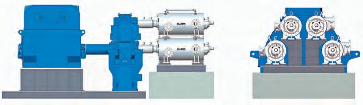
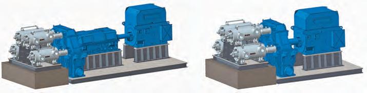
between bodies for the highest pressure ratios. Finally, the arrangement provides easy access to all four compressors for maintenance and repair using a single mezzanine or platform and crane.
The Flex-Op compressor arrangement offers a practical solution for most industrial hydrogen compression applications in the hydrogen transport and storage sectors. It is rugged and reliable and relies on proven and experienced industrial compression and gear technology that has been previously utilised in hundreds of hydrogen compression applications. Unlike many novel compression solutions that are currently under development for hydrogen, its arrangement components are all designed within well-known industrial operational limits and are commercially-available.
Case study: hydrogen
To review the applicability of the Flex-Op arrangement, a basic case study for a typical hydrogen transportation application was analysed. The operating conditions were: n Pressures: 365 psig inlet to 1015 psig discharge (2.78 pressure ratio). n Flow: 240 000 kg/d. n 100% hydrogen.
The results of the study showed that this case could be handled by a Flex-Op compressor arrangement with four casings and a total of 36 impeller stages. Intercooling would be required between the second and third compressor casing. Specifically, the resulting compressor would operate as follows: n Speed: 15 000 rpm. n Power: 7500 HP. n Intercooler between body 2 and 3. n 4 x 15MB9 casings.
The low-risk Flex-Op compressor design that utilises conventional compressor and gear technology is capable of handling this operationally-challenging hydrogen compression application.
Conclusion
The hydrogen economy requires the utilisation of compressors that are different to those that are currently used in industrial applications. For applications such as pipeline, storage and feed compression, hydrogen compressors that can reach compression ratios between 2.0 – 3.0 are required. There are several complex challenges that must be addressed when designing compressors for these applications, including light gas head rise, static and dynamic sealing, explosive safety, and material compatibility. There is significant technology development underway to design high-speed centrifugal compressors that are optimised for hydrogen compression, but this technology is not yet near maturity. Alternatively, a more conventional solution, such as the Flex-Op compression arrangement, can provide the required compression duties by utilising compressor and gear technologies that are proven and currently available.