
10 minute read
Yielding efficient operations


Michael Gaura, AMETEK Process Instruments,
USA, details the importance of an air demand analyser (ADA) in the quest to manage sulfur recovery units (SRUs) more tightly.
With the global economy recovering from the devastating impact of COVID-19 and the restrictions that were put into effect to reduce its spread, energy suppliers are aggressively working to meet deliverable volumes that have not been seen in the past two years. Coupled with the significant change in workforce that many hydrocarbon suppliers and processors have also experienced, as well as the continued push to decrease the amount of sulfur emitted at the plant or end product level, there has been a renewed effort to automate and optimise sulfur recovery unit (SRU) operations. One point within SRU operations that has specifically been receiving more focus is the inlet or feed point. Engineers and consultants are targeting the most efficient and proven method of obtaining detailed and real-time compositional data from the sour water stripper and acid gas as it enters the SRU.
It is worth recalling that the purpose of the SRU is to remove as much sulfur from incoming gas streams (feed gas) as possible, as environmental agencies want to limit the amount of sulfur emitted locally (plant level) and globally (at the point of fuel combustion).
Typically, the sulfur entering the SRU is present as hydrogen sulfide (H2S) – a compound that is lethal to human life at very low concentrations (500 ppm). The H2S is present in the sour water stripper (refinery) or acid gas (refineries and natural gas processing plants), as it has been previously scrubbed or removed from the more financially-valuable or desired hydrocarbon streams. The H2S, or any other sulfur compounds that enter the SRU, are converted and removed through reactions in the SRU plant. The most common method of removing > 90% of the sulfur is through the modified Claus process. The most common modified Claus processes currently utilised in the recovery of elemental sulfur (Sx) are based on systems that were described in detail 75 – 140 years ago. Many improvements and modifications have been integrated over this time, but the sulfur removal process
essentially follows the formula detailed below, as illustrated in Figure 1 (note: the number of converters and condensers can vary by plant and licensor).
3H2S + 3/2O2 –> SO2 + 2H2S + H2O Heat
SO2 + 2H2S –> 3/x Sx + 2H2O Catalyst
The feed gas enters the SRU containing a high level of H2S and moves through the reaction furnace where fuel and either ‘air’ or oxygen are designed to react at a temperature of at least 925°C. This temperature, and the intentional introduction of sub-stoichiometric oxygen (O2), results in approximately one-third of the incoming H2S being converted to sulfur dioxide (SO2). This conversion sets up a typical 2:1 ratio of H2S:SO2 that is required for desired elemental sulfur removal in the rest of the SRU.
Ideally, this ratio is maintained even as the process gas stream moves through the converters and condensers, which are heating and cooling the gas stream, and subjecting the process gas to catalysts that are intended to remove elemental sulfur. The elemental sulfur ultimately ends up in a storage tank or (once very common, now not so much) pit.
At this point, it is important to take note of some items that many papers and presentations have addressed in the past: n After the final condenser, there is an air demand or tail gas analyser (ADA/TGA) installed on almost every SRU. n If the ratio of H2S to SO2 is not 2:1, the SRU operator or process control system adjusts air flow to the reaction furnace to obtain this ratio. When the ratio is less than 2:1, the amount of O2 or air is often reduced at the reaction furnace. When the ratio is greater than 2:1, the amount of
O2 or air is increased at the reaction furnace. n A 2:1 ratio of H2S:SO2 is not always required or desired.
Every plant and licensor is going to find an ideal ratio for optimal recovery efficiency through the Claus process. It is important to keep this in mind when evaluating the overall
SRU operation. n The removal and/or conversion of H2S does not typically end at the last condenser in an SRU. The ADA can read ppm to % levels of H2S and SO2, often indicating that recovery efficiencies of sulfur are less than required. This is why tail gas treating units (TGTUs) are added to many SRUs. n The feed gas is never 100% H2S. The feed gas at the SRU is a combination of many gas streams that have been involved in removing undesirable components from more valuable process or product streams within a process plant or refinery. See Table 1.
A typical refinery sour water stripper gas stream will often contain concentrations of > 50% H2S, but ammonia (NH3) levels can also be 30 or 40%. Acid gas streams in natural gas plants can have nearly equal levels of H2S and carbon dioxide (CO2), 40 – 60%, as both are removed in upstream amine plant systems. Hydrocarbons can also be present at elevated and undesired levels when an upstream process upset occurs. Table 1 can be used as an approximate guide for SRU feed gas components and concentrations.
To summarise, we know that the purpose of the SRU is to remove as much of the delivered sulfur as possible from the incoming process gas stream (feed gas). We also know that there is a plant specific ratio of H2S and SO2 that should be maintained, for optimal sulfur recovery. Finally, we know that an ADA measures the concentration of H2S and SO2 at the Claus outlet, and can be used to adjust the air/O2 feed at the reaction furnace if the ratio of H2S:SO2 is not as required. However, there remains a need for additional process gas analysers.
By only measuring gas composition at the outlet of the Claus unit, users are missing out on the single biggest opportunity to operate their plant more efficiently and with more uptime. Adding a process gas analyser that monitors the concentration of key incoming components in the feed gas should be a priority for all SRU operation and design engineers.
Quicker identification of upsets
An ADA is located downstream of the reaction furnace, as well as the converters and condensers. This ADA measurement
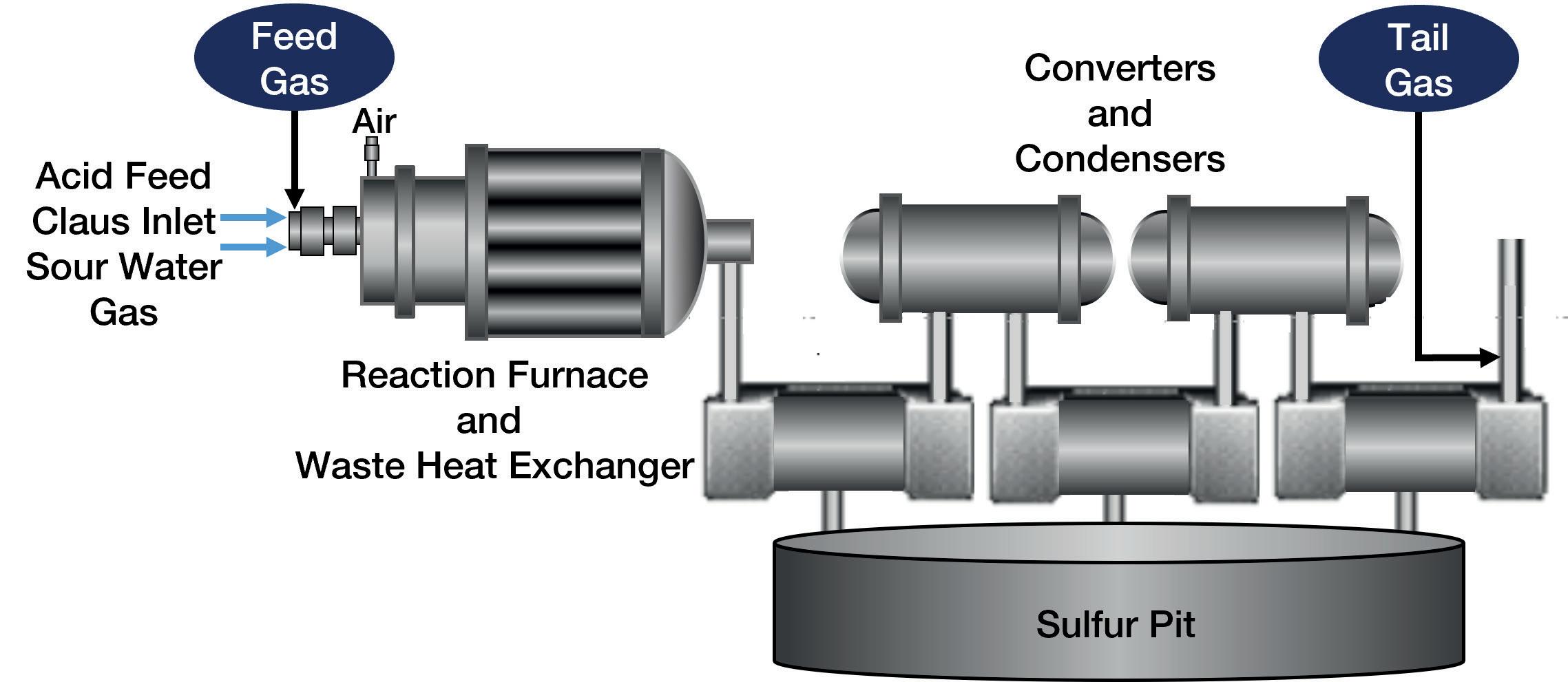
Figure 1. A typical SRU Claus system.
Table 1. Typical feed gas stream
Component Concentration (%)
H2S CO2
NH3
H2O Total hydrocarbons 30 – 100
0 – 80
0 – 70
0 – 10
0 – 2
Table 2. Oxygen consumption
Compound Moles O2 per mole hydrocarbon Ratio of O2 needed per mole hydrocarbon compared to per mole H2S
Methane 2 4
Ethane 3.5 7
Propane 5 Butane 6.5
Pentane 8
Hexane 9.5 10
13
16
19
reliably identifies changes in the ratio and/or H2S and SO2 concentrations, but not until after a considerable amount of feed gas has already entered the Claus unit. By themselves, ADAs are not fast enough for ideal process control in an SRU. At the time of feed gas introduction to the SRU, identifying process gas component concentration changes (upsets) can more accurately identify the source of the changes seen at the Claus outlet, and better protect downstream systems such as an amine-based TGTU or thermal oxidiser.
When process upsets occur upstream of an SRU, they usually involve elevated levels of hydrocarbons in the SRU feed gas. Unexpected scrubber media failure or improper amine management may result in hydrocarbons being stripped out of process streams and sent on to the SRU. As has been documented in many papers, hydrocarbons can selectively bind with the available O2, reducing the O2 available for H2S to SO2 conversion (see Table 2).
When the hydrocarbons are ‘stealing’ the available O2, and the ratio of H2S:SO2 is elevated, recovery efficiency falls in the SRU. Since correct management of sulfur recovery efficiency is critical in an SRU, automated systems and operators will adjust accordingly and increase the amount of air or O2 at the reaction furnace. This is a proper response and does frequently return the system to a desired H2S:SO2 ratio at the Claus outlet.
However, this introduction of elevated levels of O2 at the reaction furnace can have an undesirable consequence. When the upstream upset condition is corrected, and the amount of hydrocarbons suddenly returns to expected levels (or lower), the excess O2 being introduced at the reaction furnace results in the creation of too much SO2. The H2S:SO2 ratio is then lower than expected, and sulfur recovery efficiency is again negatively impacted. Even more concerningly, excess SO2 levels proceed to TGTU units and can cause issues with the scrubbing media. If enough SO2 migrates to the scrubber, replacement of all of the media may be required. Not only is this very expensive, but it may also result in the SRU operating in bypass mode and/or out of compliance. This could also lead to significant fines (more undesired costs).
Operational efficiency
In addition to sulfur recovery efficiency, SRU operational teams are also looking to maximise uptime and reduce operating costs. In lean feed applications, turndown applications, or situations where aromatic hydrocarbons or ammonia are not present, being able to run the reaction furnace at lower temperatures represents an opportunity to reduce fuel costs and minimise fossil fuel consumption – an operational ‘win-win’.
At a minimum, most reaction furnaces are operating at or above 925°C. This represents an ideal set point temperature, but in reality furnaces are running hotter (they have to in order to completely destroy impurities that are present in the feed gas, such as some aromatic hydrocarbons and NH3). If these components are not properly destroyed in the reaction furnace, they can lead to the contamination of catalyst in the Claus unit (soot), or ammonia salt formation. Both of these contaminants can lead to reduced sulfur recovery efficiency and/or SRU downtime in worst case scenarios. As such, reaction furnaces need to be run at temperatures above 1050°C or 1250°C, but ideally never above 1500°C, as this could lead to refractory damage. Measuring the concentrations of hydrocarbons and NH3 at the feed gas can allow for proper temperature management of the reaction furnace, to reduce excess fuel consumption without running the risk of damaging catalyst or other downstream hardware.
For both upset identification and operational efficiency improvements, an existing analytical system exists that is capable of measuring multiple feed gas components safely and quickly.
H2S is extremely dangerous and always at % compositional levels in feed gas streams. AMETEK has designed a sample probe, sample handling system, and analyser designed to minimise the risk of H2S exposure to maintenance and operational teams. This is referred to as the AMETEK feed forward IPS-4 solution, adding additional measurements and safety considerations to those already using an AMETEK 9xx analyser to measure the feed gas component concentrations.
The measurement needs to be continuous, with minimal lag and sampling times. Ultraviolet (UV) and infrared (IR) technologies integrated in the AMETEK IPS-4 allow for the continuous measurement of H2S, NH3, CO2 and hydrocarbons, with minimal maintenance and no consumable components.
Conclusion
If you interview a good chef, they will always tell you that the best way to ensure satisfied diners is to choose the best ingredients possible, monitor the cooking process as much as possible, and constantly solicit feedback from the consumers. Many SRU professionals will struggle to compare their SRU operations to a restaurant – and justifiably so – but AMETEK believes that the time has come for SRUs to be managed more tightly, in order to ensure greater end user satisfaction (end users being environmental compliance teams and regulatory agencies, and operational engineers).
The ADA provides insights on the concentration of H2S and SO2 leaving the Claus plant, and is already present in SRUs. Adding an AMETEK IPS-4 feed forward analyser system provides more insights into what is entering the SRU (the ‘ingredients’), allowing greater process control throughout the Claus unit and SRU.