
7 minute read
Getting fired up


Stuart Bradbury and Doug Sinitiere, Carboline Global Inc., delve into the grudge purchase mindset and optimisation opportunities for passive fire protection products or systems used to mitigate the thermal effects of fire in the downstream sector.
To most, passive fire protection (PFP), also referred to as ‘fireproofing’, remains a misunderstood subject. It carries a reputation throughout the hydrocarbon industry, best described as a grudge purchase, simply because it is required in some capacity but should never have to realise its intended use in a perfect world. It should be considered as an insurance policy. However, despite its extensive use to mitigate the thermal effects of fire following accidental releases, knowledge gaps remain regarding hazard analysis, the role of fire risk assessment, and material selection, which habitually feed the grudge narrative.
Broadly speaking, PFP represents a passive barrier approach comprising various fire-resistant insulation materials or systems to protect safety and environmentally-critical elements (SECE), including structural steel support structures (see Figure 1), from credible fire hazards following the initial outbreak.
Fundamentally, PFP materials or systems function by limiting heat transfer from the release source, in effect delaying temperature rise in the protected members or separating elements to maintain, for a time equivalent period, stability, integrity and insulation to limit escalation, maintain the functional performance of critical systems, and to facilitate emergency response actions.
Hazard analysis
Due to the processing, refining or storage of hydrocarbons, downstream and midstream facilities can produce a complex range of fire and explosion hazards. The extent of the release
will determine the exposing fire scenario, the possibility for escalation, and the severity of the consequences.
A prescriptive approach to defining the extent of coverage for PFP material use has commonly been used to address credible fire scenarios in the onshore process industry. For example, API RP 2218 can generally be considered a prescriptive approach to addressing PFP requirements. API RP 2218 provides guidance on defining the extent of fire protection zones, the scope of coverage to SECE, the time equivalent durations or period of resistance, and single-member protection thickness determinations based on material response standards such as ANSI/UL 1709 for pool fire (non-pressurised release) scenarios using a defined maximum allowable temperature.
In contrast, performance-based or inherent safe design practices employ a quantitative risk assessment approach to defining the exposed fire scenarios based on the nature of the process (pressure and temperature), inventory type, leak release rates, and the total inventory at risk in order to determine design accident loads. A mitigation effort is more wholesome, and takes engineering controls – such as EDP, ESDV, drainage, isolation and plant layout – into consideration when addressing the requirement for PFP to SECE. Implementing performance-based design methods will require early engagement in the FEED stage to realise the potential optimisation benefits of such schemes.
Regardless of the approach, failure to adequately define and assess the role of PFP materials in the development of risk assessments may lead to the lack or excessive use of PFP materials on SECE.
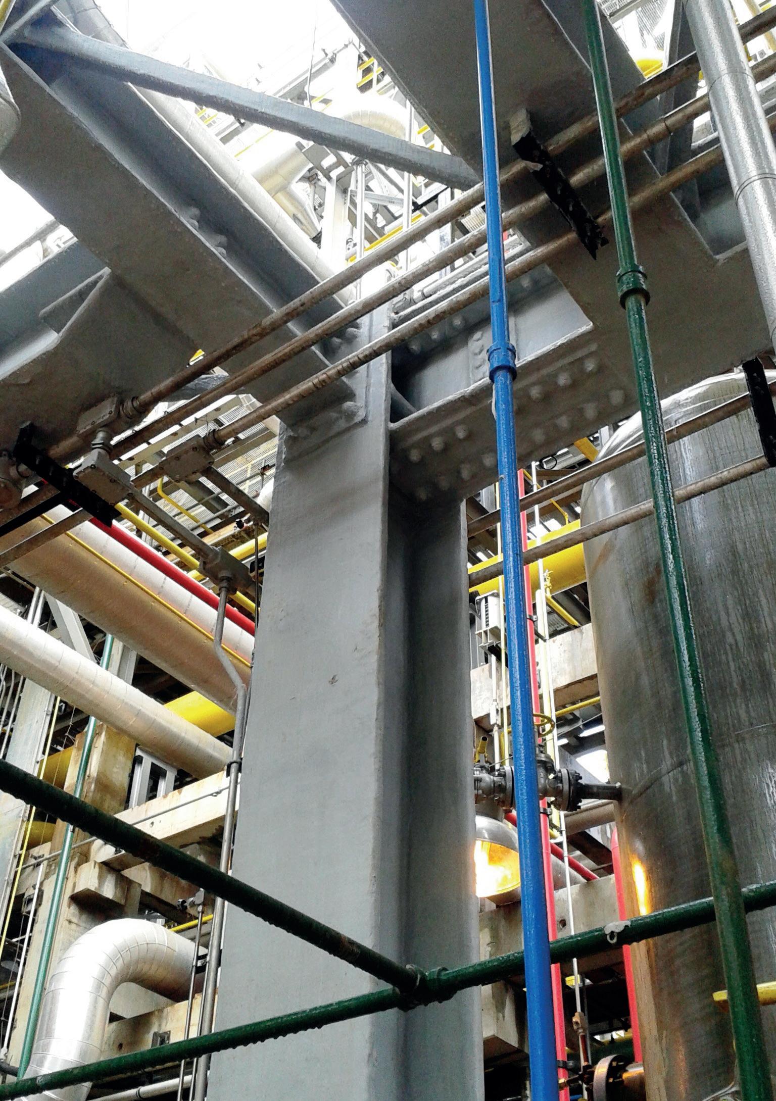
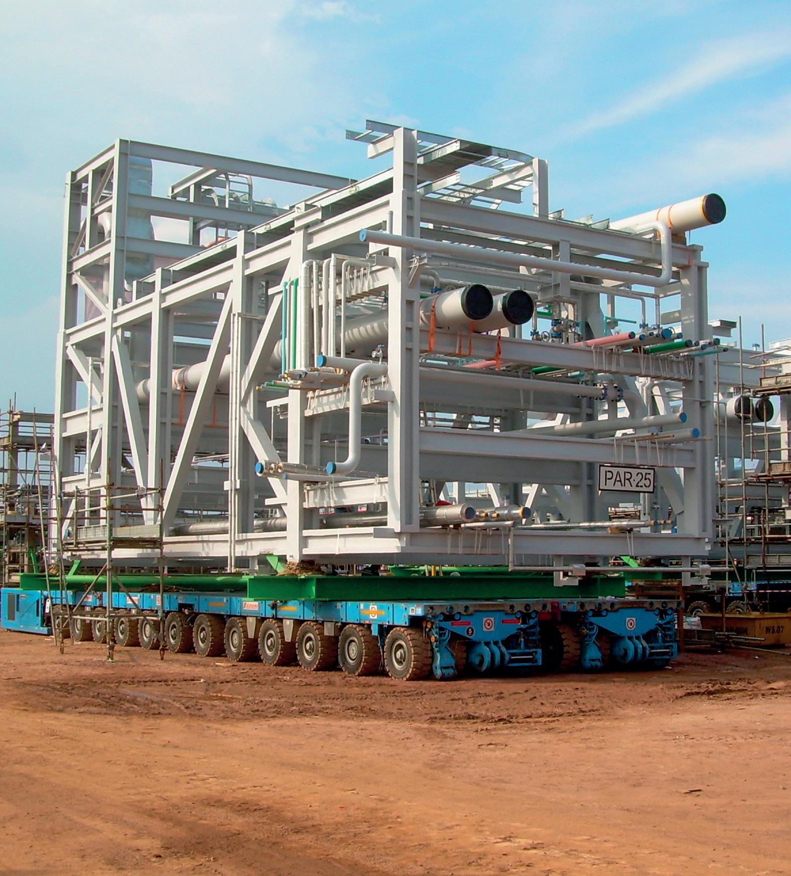
Figure 1. Structural steel fire protection (top: epoxy intumescent; bottom: lightweight cementitious).
Developing PFP performance requirements for structural steelwork
Once the requirement for implementing a PFP measure to mitigate a fire hazard has been identified, the performance requirements and specification development can be similarly addressed using either a prescriptive approach or an optimisation approach through engineering analysis. The performance of any PFP material used to protect SECE that has been identified to be protected from credible release scenarios is based on the following considerations: n Exposing fire type – pressurised, non-pressurised or combination releases. n Period of resistance – total duration of the exposing fire, or the time equivalent at which failure of a protected member should not occur. n Critical core temperature – the maximum allowed temperature vs time equivalent to ensure that sufficient strength and stiffness remains in the protected member to its capacity.
Published fire test standards do not represent natural fires. However, they do provide reproducible methods to evaluate PFP performance and the thermal response of the protected substrate over a time equivalent duration. Test standards such as ANSI/UL 1709 are commonly used and specified to evaluate PFP material response to simulated pool fires using the rapid rise time-temperature curve and prescriptive acceptance criteria, including maximum allowable temperature. For jet fires, a common approach is to use ISO 22899-1, as tested in Figure 2.
Generally, API RP 2218, which is widely adopted in the downstream and midstream world, has defaulted to a single protection thickness approach based on a member size of a W10x49 for an equivalent time, regardless of utilisation and thermal heat sync of the member to be protected. The single
protection thickness approach may well be applicable in members with a greater thermal mass than the tested section. Yet it remains important to question whether this qualifies as excessive use of PFP, and if the grudge is being fed without cause.
The concept of section factor can be used to determine the protection thickness of a PFP material for a given steel shape vs maximum allowable temperature for a defined period of resistance. Section factor is a measure of the rate at which a steel section will heat up with energy. A steel section with a large surface area will receive more heat than a smaller surface area. Additionally, the greater the volume of the section, the greater the heat sink. What this means is that a small thick steel section will have a slower rate of temperature increase in a fire when compared to a large, thin one, and as such will require less material to be applied while still achieving the exact performance requirements, as illustrated in Figure 3.
This method can be considered in both prescriptive and performance-based approaches. Some of the benefits of reducing PFP protection thickness for project stakeholders –but still mitigating the risk of the identified hazards – include the following: n Material and labour cost savings. n Schedule improvements. n Reduction in applied weight per member surface area. n Reduction in scaffolding and transportation costs. n Reducing embodied carbon emissions.
Although reducing emissions is not directly related to mitigating fire hazards, applying a protection thickness method through regression analysis and the section factor concept may result in less material being produced, manufactured and shipped, thus providing a sustainable approach.
Additional optimisation efforts that are performance or engineering-based can further help to rationalise the extent and use of PFP to mitigate process hazards above and beyond what has been discussed, including modelling, structural response, and critical temperature assessment based on utilisation to capacity redundancy analysis, etc.
There is still room for entertaining both approaches when evaluating prescriptive and performance-based design. For example, depending on the process and equipment involvement, an asset owner may find it reasonable to assign a prescriptive approach to one portion of the process while focusing on regression analysis for a part of the project. This would deliver some benefits that would be meaningful if to address current commercial and economic circumstances. What is needed is the technical justification for such an approach.
Additionally, when large global projects started moving significant modules and equipment overseas and far away from operating sites, a complete commercial evaluation had to take place for consideration well outside of just the material itself. The assessment included the total weight of coated steel, transport cost, site considerations – including access – and other things related to material selection. Other items to consider are how materials would survive in the long-term operating environment. For example, when considering a low-probability event, how would materials perform in these environments and continue to provide fire and thermal protection?

Figure 2. ISO 22899-1 PFP material testing.
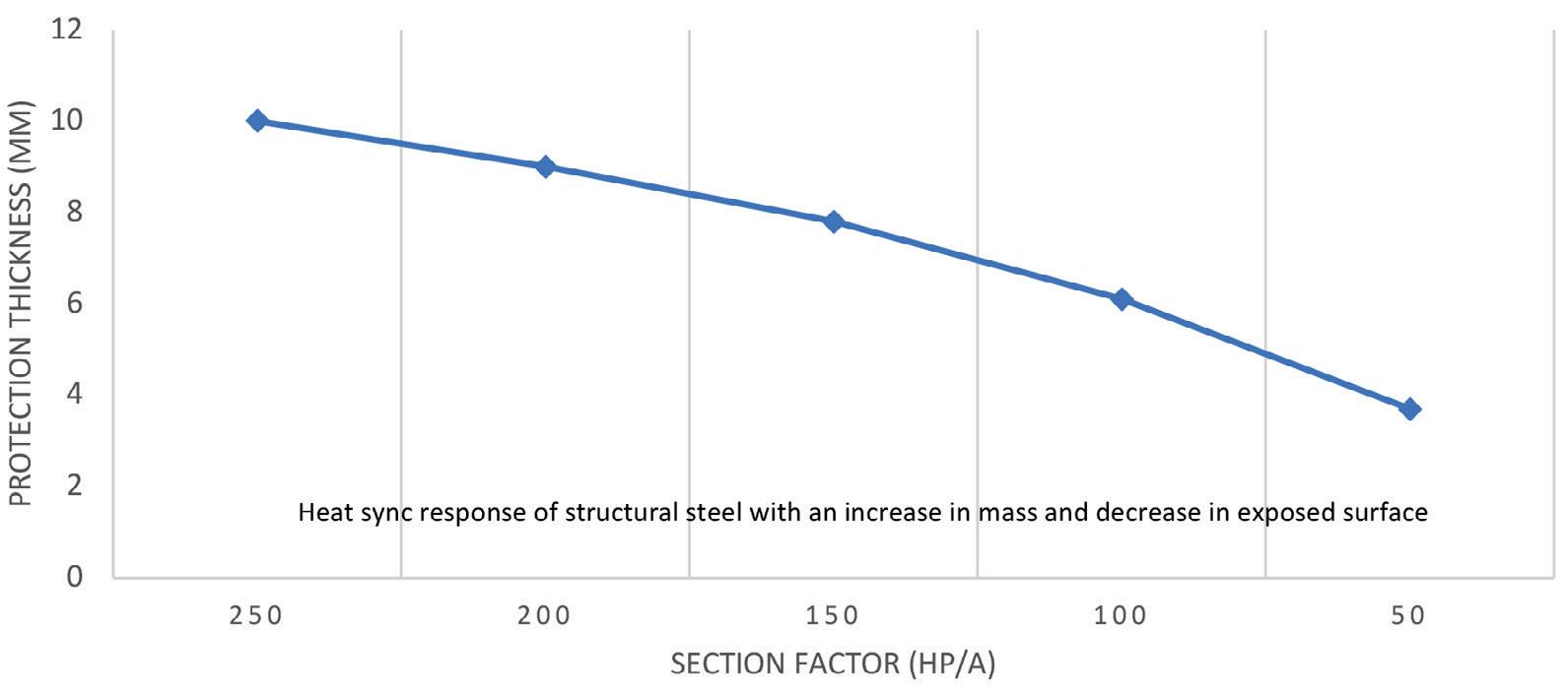
Figure 3. Epoxy intumescent paint – protection thickness vs MAT of 538°C for 120 minutes of resistance.
Conclusion
The shift from grudge to gratification for PFP materials can be realised. It takes time, effort and early engagement with subject matter experts and material manufacturers to develop fit-for-purpose solutions to meet the hazards’ performance requirements optimised to benefit all stakeholders for a life in service. The gratification is that the most optimised approach is taken, achieving optimum efficiency. The commercial impacts of this are measured not only in the material itself but in all the related items that accompany it. So, where else can we take this approach? Can other elements in projects be optimised and made more efficient? Perhaps optimisation provides a starting point, but we should challenge ourselves and consider other areas where these efficiencies can be achieved. Time will tell, but we certainly have a way forward that results in some real solutions for now.
Bibliography
• API Recommend Practice 2218, Third Edition, Reaffirmed, ‘Fireproofing Practices in Petroleum and Petrochemical Processing Plants’, (March 2020). • ANSI/UL 1709, Fifth Edition, ‘Standard for Safety for Rapid Rise Fire Tests of Protection Materials for Structural Steel’, (24 February 2017). • FABIG Technical Note 13, ‘Design Guidance for Hydrocarbon Fires’, (September 2014). • Energy Institute, First Edition, ‘Guidance on Passive Fire Protection for Process and Storage Plant and Equipment’, (March 2017). • PFPNet, Issue 01, ‘A Guide to Developing a PFP Scheme for a Hydrocarbon Facility’, (January 2020).