10 minute read
Pattern vs performance


Air-cooled heat exchangers (ACHEs) at hydrocarbon processing or power plant facilities occupy large areas. Non-uniform airflow patterns and non-ideal site installation can affect overall plant performance, sometimes significantly reducing output. Industry guidelines addressing these problems are limited, and in-house rules of thumb are not consistently applicable.
Heat Transfer Research Inc. (HTRI) conducts research on many ACHE operational challenges, revealing complexities in phenomena on the airside. Some issues of concern include the following: n Non-uniform approach of air into the ACHE inlet is the most common cause of deficient fan performance, and is often associated with obstructions from buildings, pipelines, or ground equipment. n Wind can direct the heated exhaust air away from or back into the unit. Some plant sites cannot avoid installing ACHEs in known wind corridors. n Hot air recirculation, a form of airside maldistribution, is difficult to predict. It creates temperature pinches that reduce mean temperature differences and subsequently the heat transfer potential of the tubeside process to reject heat to the air.
Salem Bouhairie and Syed Haq,
Heat Transfer Research Inc., discuss how airflow patterns within air-cooled heat exchangers (ACHEs) degrade performance.
This article discusses some of HTRI’s findings from collected field data, thermal plume visualisations, and computational fluid dynamic (CFD) simulations. The analysis helps to explain the impact of these phenomena on ACHE operation, and suggests some solutions.
Most ACHEs designed using American Petroleum Institute (API)1 or Heat Exchange Institute (HEI)2 guidelines use fans operating as forced-draft units, pushing air across the tube bank. Units that are more efficient operate in induced-draft (or natural-draft) configuration, where fans pull air across the bundle. Natural-draft ACHEs, which use thermal-buoyancy-driven airflow to cool the process, are increasingly used. These units cost less to operate since they do not require fans or motor-drive machinery. Additionally, the number of environmental permits authorising the use of natural-draft units to reduce noise has increased.
Using air to cool a tubeside process is thermally inefficient since air has a low thermal conductivity. The common solution is to design ACHE tube bundles with enhanced surfaces: high-fin tubes help to overcome airside thermal resistance under ideal air ambient conditions. However, operators face several challenges during off-design air-cooling when trying to meet product demand. Compared to tubular or plate-type exchangers, ACHEs require much

larger amounts of site area for the same processing capabilities. A typical bank of ACHEs, as shown in Figure 1 (bottom), is often located in non-optimal arrangements due to plant plot limitations. The non-ideal site installations predispose ACHE banks to non-uniform airflow patterns that can significantly reduce overall performance. Guidelines are very limited in addressing airside problems, leaving industry to use in-house rules of thumb that are not consistently applicable.
At the HTRI Research & Technology Center, research conducted on the air-cooled unit (ACU), an API-661 unit shown in Figure 1 (top), measures ACHE performance and the adverse effects of non-ideal airside phenomena such as: n The non-uniform approach of air into the ACHE inlet. n Wind effects. n Hot air recirculation.
Several thermocouples and static pressure sensors measure the temperatures and airflows across the bundle. The ACU’s weather station measures various ambient psychometric properties (wet and dry bulb temperatures, humidity, and outdoor pressures) and wind velocities (magnitude and direction). The ACU provides a unique opportunity to tune CFD models to test the measurement of an API 661-compliant unit.
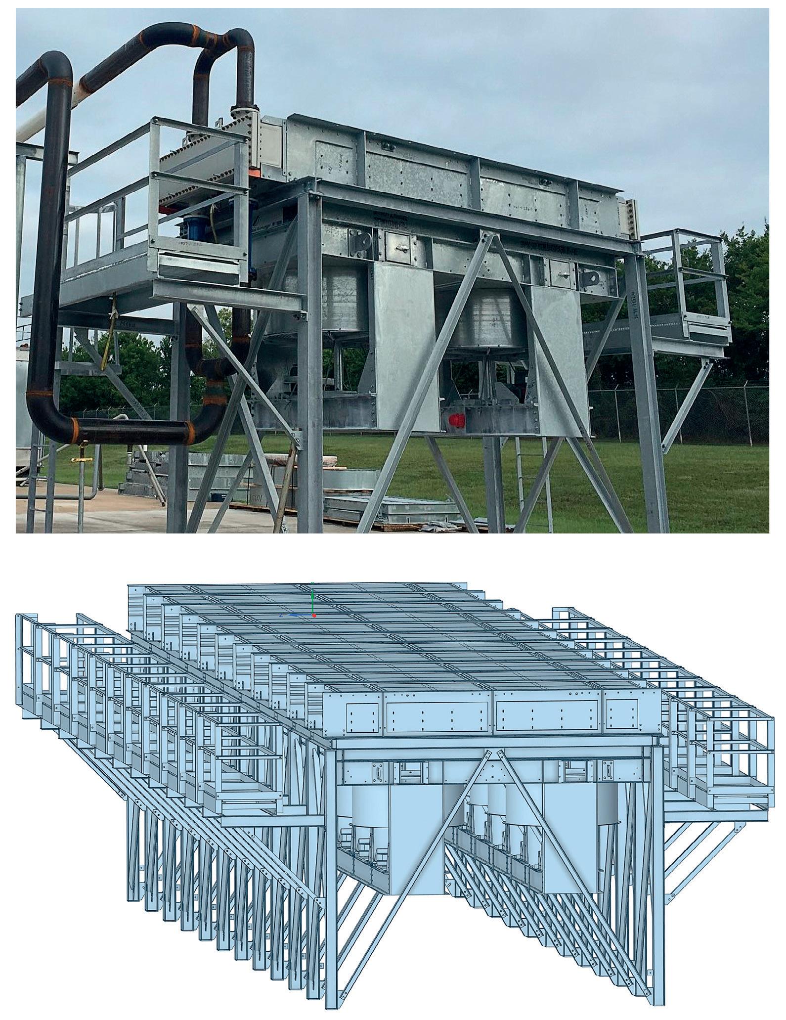
Figure 1. Side view of a single ACU bay (top) arranged as a bank of forced-draft air coolers (bottom).
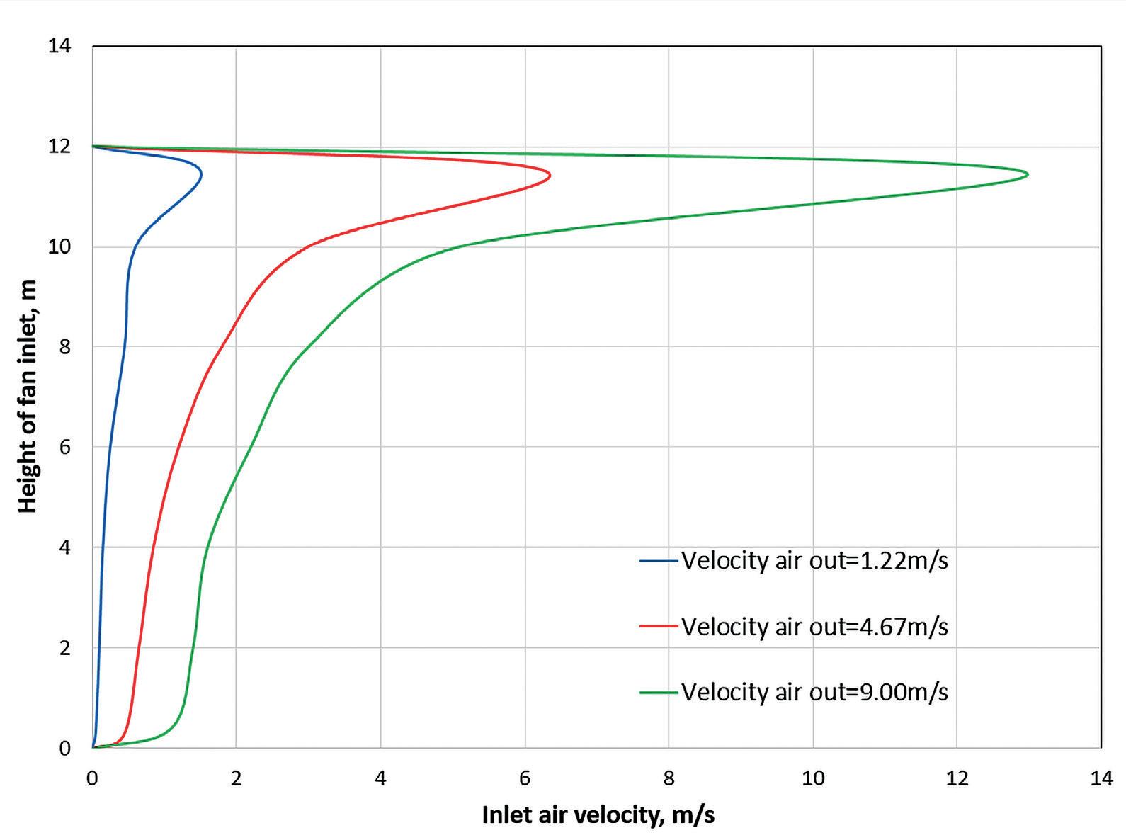
Figure 2. Profile of inlet air velocity with fan 12 m above ground.
Non-uniform air approach
The non-uniform air approach into the ACHE intake is the most common cause of deficient fan performance. API 661 provides airside design recommendations for controlling approach and discharge air by considering fan height ground clearance and air discharge kinetic energies.1 Non-uniformity develops due to a combination of ground resistance on approach air and change from a horizontal approach to a vertical intake, resulting in uneven flow distribution at the fan impeller. Duvenhage and Kröger conducted several experimental and numerical studies on ambient approach air without wind.3 They concluded that assuming uniform air velocity at the inlet side of an ACHE is inadequate when the mass flow rate exceeds a critical value for a specific fan height above ground (see Figure 2). Some solutions to reducing the effect of a non-uniform air approach include draping the ACHE sides with porous windscreens below the plenum. The windscreens help to reduce the vertical gradient of the approach air.
Blockages around the ACHE may also cause a non-uniform air approach. These blockages include support structures, header piping, fan motor, or even adjacent fans in an ACHE bank. HTRI investigated the effect of blockages based on the open approach area available for air to enter the ACHE perimeter. As a general trend, when the open approach area around the ACHE reduces, the intake airflow reduces. This useful rule of thumb accounts for blockages around an ACHE. However, it does not present the complete picture. In-depth analysis is required to realise the potential performance reduction caused by the blockages.
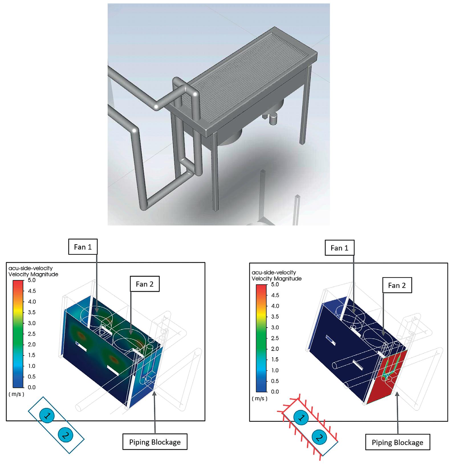
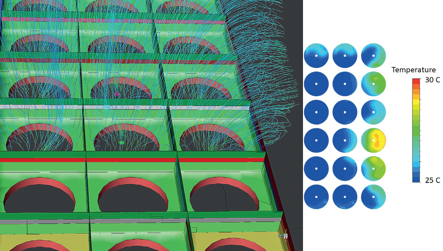
HTRI’s CFD simulations predict that blockages cause flow maldistribution across the ACHE. Reduced airflow to the fans, which results in its starvation, can have detrimental effects on the life of the fan. In extreme cases of blockages, the local velocities coming into the ACHE are three to four times faster than the unobstructed flow.4 Such variations can place large mechanical stresses on fan blades, which are essentially cantilevers. The damage to the fans can vary, depending on the location of the blockage. Figure 3 shows velocity distribution contours around the HTRI ACU (top) with unobstructed flow with some pipe blockage (bottom left), and with three sides blocked (bottom right). With three sides completely blocked, not only are the velocities much higher, but the minor blockage of the piping also has a much more significant effect. Additionally, Fan 2 near the open (red) side experiences a completely different flow profile compared to the Fan 1 at the
opposite (blue) side. Flow maldistribution between the ACU’s fans can be as high as 30% of the total ACHE airflow.4
Flow maldistribution inevitably leads to temperature maldistribution. A significant temperature difference is observed between fans’ cells, when the flow maldistribution between fans is greater than 20% of the total flow. The maldistribution can lead to tube bundle hot spots and temperature pinches, resulting in underperformance of the ACHE. In the long-term, this can lead to finned tube degradation, and the ACHE may require servicing sooner than anticipated.
To reduce non-uniformity due to external blockages, it is advisable to ensure that the surrounding equipment is placed in such a way that flow behaviour between fans is as symmetrical as possible. In the event of existing blockages, periodic inspections of the ACHE need to be conducted to check for possible deterioration of the equipment.
Wind effects
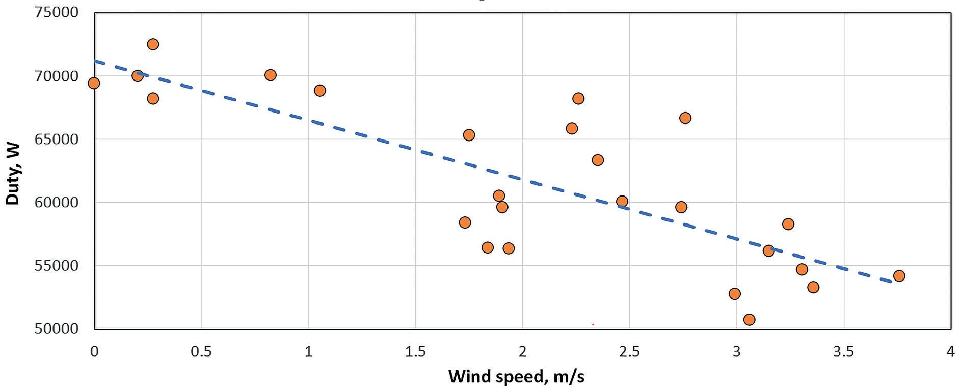
For forced-draft units, wind generally has a negative effect on fan performance. High wind speeds increase the velocity pressure of the inlet air stream of the ACHE. This in turn increases the static pressure loading on the fan, causing the fan’s operating point to shift. The result is a higher operating static pressure at a reduced airflow rate. Typically, the fans that are subjected to the greatest degradation in performance are those on the leading face (upwind) of the ACHE.2 For natural-draft units, high crosswinds flatten the plume height, reducing the airflow through portions of the heat exchanger
bundle. Figure 4 shows that an increasing wind speed can hamper ACU duty. Some common solutions to reducing wind effects are to install windwalls above the plenum deck, and windscreens HalfPageBrandAd_Apr2022_final.pdf 1 5/9/22 10:56 AM below the deck. Windwalls separate the discharge air stream of
Figure 3. Comparison of an ACHE (top) with unobstructed flow (bottom left), and with three sides blocked (bottom right).
the inlet air stream. Chimneys should be mounted on natural-draft air coolers to increase the buoyant draft and subsequently the duty of the ACHE. If ACHE banks are not yet installed at a plant, it is better to align the long side of the ACHE banks with the wind direction rather than the short side. The air intake at the long end of the bank is farther away, reducing the chance of the bank receiving wind-blown hot air exhaust.
Hot air recirculation
The most difficult non-ideal airflow to predict is hot air recirculation. Some of the discharged hot air can travel downward and re-enter the cooler, as shown in Figure 5. In fact, neighbouring ACHEs competing for the air supply, with and without wind, can induce recirculation. Forced-draft ACHEs generally have lower exit velocities than their induced counterparts, and are therefore more prone to hot air recirculation.
Airside recirculation is aggravated by several factors:5 n Poor inlet aerodynamics. n Weak outlet plume velocity. n Strong multidirectional crosswinds. n Alternate fan on/off operation. n Proximity to other air coolers, equipment, piping, or buildings. n Low ground clearance.
API 661 provides recommendations for fan coverage, plenum depth, fan-cell partitions, approach and exit velocities, and airside kinetic energy that can help minimise airside maldistribution.1 However, following these guidelines without understanding the physics behind their intent does not always prevent hot air recirculation. Detailed information on the local flow and thermal maldistribution throughout the air-cooler tube bundles is often unavailable. In the HTRI ACU, thermocouples installed at the fan inlet help detect whether temperatures are greater than ambient, and confirm hot air recirculation. HTRI also performed CFD simulations of hot air recirculation, which revealed that recirculation increases with greater heat exchanger length and wind speed.5
Some solutions to the recirculation problem include using induced-draft ACHEs where their fan ring discharges exhaust higher and farther away from the inlet, positioning banks of ACHEs far apart, and having high ground clearance. It should be noted that some ACHEs deliberately induce ‘warm air’ recirculation through louver controls to deliberately warm tubes and prevent bundle freeze-up (warm air recirculation) in cold climates. HTRI will use future experimental measurements in conjunction with these CFD simulations to improve the prediction of hot air recirculation and improve ACHE design and operation.
Conclusion
ACHE designs should consider ambient air non-idealities to help ensure reasonable and cost-effective unit performance. HTRI has studied many of these problems through experimental testing and numerical simulations, with the aim of improving ACHE performance. Non-uniform air approach with and without blockages can result in intake flow maldistribution, which can be resolved with windscreens or symmetrical placement of surrounding equipment. Wind effects can increase fan static pressure and reduce natural-draft airflow, but windwalls, chimneys, and ACHE bank alignment with the plant-site wind corridors can alleviate these problems. Several factors can aggravate hot air recirculation, making it most difficult to predict. However, some Figure 4. Wind speed effects on duty for ACU with a 1.2 m (4 ft) solutions include using induced-draft ACHEs, adding chimney. sufficient inter-bank ACHE spacing, and ensuring good ground clearance. In addition to this, ‘warm air’ recirculation can be used to improve ACHE operation in cold climates. Overall, understanding irregular ACHE airflow patterns helps engineers to make informed decisions when modifying designs, by adding devices or adjusting operational approaches to improve air cooler performance.
Figure 5. Discharged hot air recirculating over the ACHE perimeter and raising local inlet temperatures of outer bank fans.
References
1. API STD 661: Petroleum, Petrochemical, and Natural Gas Industries – Air-cooled Heat Exchangers, 7th ed., American Petroleum Institute, (2013). 2. Standards for Air Cooled Condensers, HEI-3087, 1st ed., Heat Exchange Institute Inc., (2011). 3. DUVENHAGE, K., and KRÖGER, D. G., ’Plume recirculation in mechanical-draft air-cooled heat exchangers’,
Heat Transfer Engineering, Vol. 16, No. 4, (1995), pp. 42 – 49. 4. GANGULI, A., MARNER, W. J., WEIERMAN, C., and CHENOWETH, J. M., ‘AC-5 Airflow problems in forced draft air-cooled heat exchangers’, Heat Transfer Research Inc., (1986). 5. BOUHAIRIE, S. A., ‘AC-17 CFD simulations of airside maldistribution around API air cooler’, Heat Transfer Research Inc., (2016).