
5 minute read
The challenges and opportunities of virtual engineering


Carina Wegener, REMBE GmbH, Germany, discusses how to achieve the right installation torque with a virtual calculation.
Determining the required installation torque for a leak-tight flange system is a daily challenge for industrial valve manufacturers and plant operators alike. All of the components in the flange system have individual installation requirements, and environmental considerations add further difficulty to the task. The collaboration between the individual component manufacturers and the plant operator is crucial to everything working in harmony. This article will describe the challenge in greater detail, and outline the possible solutions that are available.
Selecting the installation torque
Generally, there are different approaches when it comes to selecting the required installation torque. Alongside manufacturer information for individual components, there are calculation standards such as DIN EN 1591-1 or the AD 2000 set of rules, with which conventional flange systems can be calculated analytically. According to these standards, a conventional flange system (see Figure 1, left) is defined as a flange inlet, flange outlet, gasket and connecting elements (e.g. bolts). In practice, a flange system is often expanded by additional components (see Figure 1, right). This can be a pressure protection mechanism, such as a rupture disc. A rupture disc is usually installed with a mounting unit, consisting of a holder inlet and holder outlet. A second gasket is also required.
The conventional calculation standards become invalid for these expanded flange systems, as the equations underlying these standards do not take any additional components into account. Metallic sealing surface contact has also been excluded up until now, as have systems whose stiffness
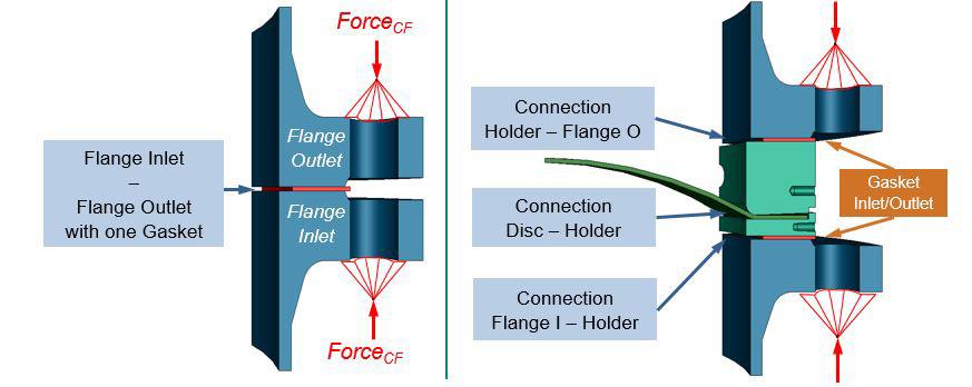
Figure 1. Comparison of a conventional flange system (left) and a flange system with rupture disc and holder (right).
fluctuates greatly over the width of the gasket. Notably, metallic sealing surface contact will be integrated into future requirements due to the amendment of the Technical Instructions on Air Quality Control (TA Luft).
From the perspective of the rupture disc manufacturer, the requirements for the design of the flange connection are primarily determined by the functionality of the rupture disc. With regards to the connection between the holder and rupture disc (see Figure 1, right, connection disc – holder), the contact pressure must be sufficient in order to hold the rupture disc and prevent it from being pulled out during the process. The system must also be tight so that the medium does not leak out. That being said, the contact pressure cannot be so high that it leads to the destruction of the rupture disc material. As a result of these factors, there is a range of permitted surface pressures in this connection, which must be set via the installation torque.
A gasket manufacturer focuses on the sealing point between the flange and gasket (see Figure 1, connection flange – gasket). Every gasket manufacturer specifies a minimum and maximum sealing surface pressure, creating a range which must also be set via the installation torque. Two different requirements for the necessary installation torque are produced: in most applications, rupture discs are manufactured from stainless steel, whereas gaskets are often made from non-metallic materials. Different materials with different properties each have a specific required surface pressure. To adjust this surface pressure, however, only one shared installation torque is to be set for both cases. This creates an optimisation problem.
The solution lies in the geometric alteration of the contact surfaces between the rupture disc and holder, and is therefore down to the rupture disc manufacturer.
Due to the metallic sealing in this connection (see Figure 1, connection disc – holder), the required surface pressures in this range are usually higher than the permitted gasket compression. With targeted design measures, excessive tension is created in the sealing surface between the rupture disc and holder. This allows the optimum surface pressure to be set in the sealing surface without the surface pressure in the gaskets increasing to an inadmissible extent.
In addition, when calculating the installation torque, it is important to investigate whether the components of the flange system are overloaded in the respective constellation. Installing a rupture disc and a holder in a flange system causes the mechanical properties of the overall system to change. This results in greater flange blad tilt and tension in the flange.
If the rupture disc is triggered by an overloading of the process, it must then be replaced along with the gaskets. However, the flange and holder are often used multiple times and must retain their function-securing geometry after repeated dismantling and installation. Permanent plastic deformations in the loading conditions installation, testing and operation are therefore not permitted. To ensure this, a strength test must be carried out for the configuration, which ensures a sufficient distance from the material’s elasticity limit for all loading conditions.
Conclusion
All of the required calculations for configuring the installation torque cannot currently be performed with sufficient precision, using analytical calculation principles. Having taken into account the complexity and the ever-greater challenges of the configuration of the installation torque, REMBE uses virtual engineering with the finite elements method. This makes it possible to depict the flange system – including all additional components – as a digital twin, and thus simulate its mechanical behaviour before manufacture and commissioning. With this digital twin, the mutual influences of all of the components are taken into account in advance, before being brought together in reality.
The simulation results and empirical knowledge are then used to optimise the individual components virtually until all of the components are in harmony with their specific installation requirements. Only after this are the components manufactured or ordered, and then installed.
REMBE offers such calculation services. For plant operators, there is no longer the need to involve an engineering firm or similar service providers. The customer receives a complete solution with real added value, including reliable simulation results calculated by specialists, which then flow into the customer-specific manufacture of the rupture discs.


