
7 minute read
Finding the right fit


Peter Foith, CS Combustion Solutions, Austria, outlines the challenges faced when retrofitting an existing thermal stage of a sulfur recovery unit.
For the retrofit of a 700 tpd Claus plant with specific challenges, CS Combustion Solutions utilised its accumulated experience in designing and engineering combustion systems for sulfuric acid production, based on combustion of sulfur containing liquid and gaseous streams, spent acid regeneration units, and hazardous waste incineration, to supply new equipment. This included a low pressure drop swirl burner with staged combustion of Claus gas, a reactor utilising a Blasch VectorWallTM, and a new waste heat boiler with a focus on minimising the pressure drop to meet the clients’ requirements.
Initial situation
Burner
The retrofit project started with the company analysing the existing equipment and engineering new equipment to overcome the various challenges. The original burner onsite was a multi-flame burner with low pressure drop on the Claus gas thermal stage, with undefined mixing of combustion air and Claus gas, which leads to low flame stability in low load cases as well as during start-up. The reason for the undefined mixing was found in the design of the original burner, as the
underlying construction of the multi-flame burner, with 48 individual ceramic blocks for each of its 48 flames, is prone to poor Claus gas distribution in low load cases if the ceramic blocks are not centrically placed. In addition to this, corrosion was prevalent due to condensing of Claus gas in these situations.
Reactor
The original reactor was equipped with a checkerwall in the first third of the chamber. However, even though a checkerwall generally helps to improve temperature distribution in the reactor, in this case the temperature distribution was not homogenous and hot spots would lead to refractory damage, as it would burst over time due to stress in the material. Another major reason for using a checkerwall is to facilitate the conversion rate of hydrogen sulfide to sulfur, as a high conversion rate is a key factor for an efficient Claus plant. Unfortunately, the checkerwall did not lead to satisfying results, as the conversion rate was inefficient and below expectations. As there was the additional problem of the long burner flames coming into contact with the checkerwall, it was surmised that the position of the checkerwall was not ideally selected, which could have been the reason for the aforementioned problems in the reactor.

Figure 1. CS Combustion Solutions’ low pressure swirl burner. S1= secondary air, S2= primary air, S5= Claus gas first stage, S6= Claus gas secondary stage.
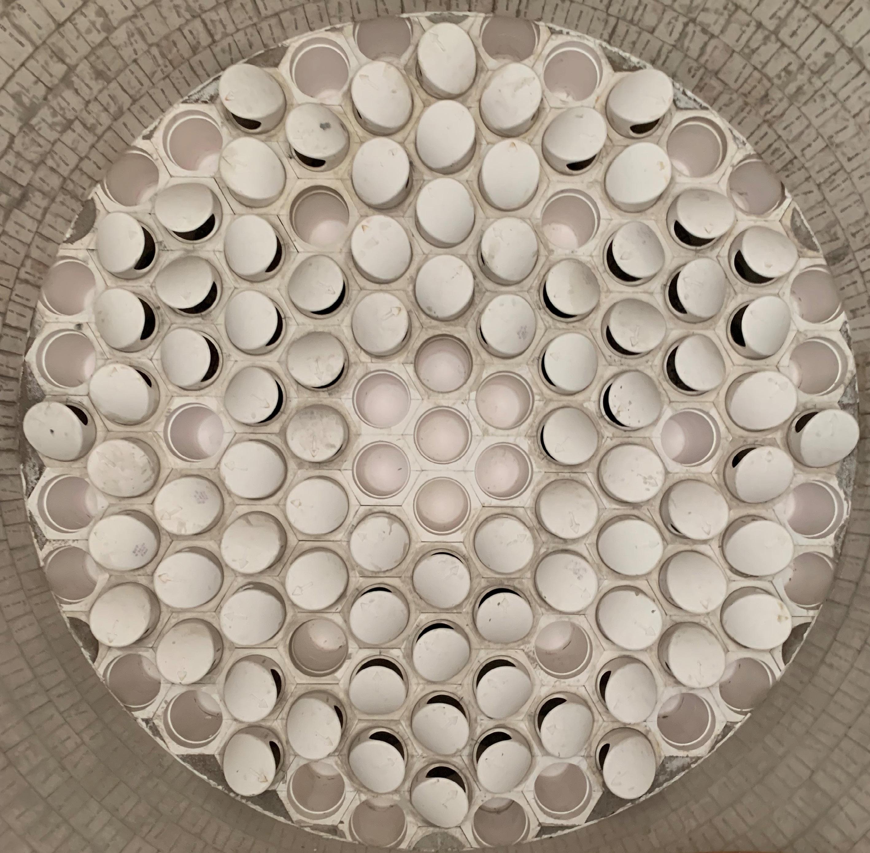
Figure 2. VectorWall. Waste heat boiler
The original waste heat boiler was a smoke tube boiler with an internal bypass, with the steam drum directly installed on the boiler. The total design steam capacity of the equipment was 75 tph, and the steam had a temperature of 250°C at a pressure of 36 bar(g). In comparison with the reactor, the waste heat boiler operated more effectively and with fewer issues. However, a recurring problem with welding cracking was prevalent with the boiler and arose due to thermal stress caused by an inhomogeneous temperature profile.
Challenges
Together with specified expectations from the client, the initial situation highlighted certain issues, resulting in challenges that led to various complexities. These were met with the following necessary engineering efforts: n As the focus of the retrofit was only on the replacement of the existing thermal stage, it was necessary to ensure that all process parameters remained unaffected, so that the equipment upstream and downstream of the thermal stage continued to work as intended. n The existing multi-flame burner was required to have a low pressure drop on the Claus gas side, as the available supply pressure was very low. The available combustion air pressure was also low. This meant that the new burner required a low pressure drop for Claus gas and combustion air, while ensuring a high enough turbulence for proper mixing of both in order to achieve a stable flame for low and high load cases. n A further requirement was to ensure a high hydrogen sulfide to sulfur conversion rate to meet the client’s specifications and expectations. n The available space for the new thermal stage equipment remained the same, as the upstream and downstream equipment was unaffected by the retrofit. This meant that the overall size and dimensions of the burner, reactor and waste heat boiler also remained the same.
Addressing these challenges meant the target for the maximum pressure drop through the complete thermal stage unit (burner, reactor and waste heat boiler) was 100 mbar(g).
The aim for the burner was a low pressure drop design on the Claus gas and combustion air side to meet the issue of low pressure availability. The burner design also needed to ensure flame stability by generating a sufficiently high turbulence and mixture of combustion air and Claus gas across all load cases.
Additionally, the aim was to not only get as close as possible to the theoretical maximum achievable hydrogen sulfide to sulfur conversion rate of 70% at these process parameters of 1338 K in order to meet the guaranteed
conversion rate of 65%, but also to increase the maximum sulfur capacity to 120%.
Meeting the challenges and requirements
Low pressure swirl burner
Based on existing and proven CS Combustion Solutions burners, a new low-pressure, double-staged swirl burner (see Figure 1) was designed to meet the requirements of low pressure drop on the Claus gas and combustion air side, while ensuring proper mixing.
New reactor
The existing reactor made use of a checkerwall, however due to the requirements for this project, the company decided to utilise a VectorWall (see Figure 2) for the new reactor, which has the same dimensions. This VectorWall was specifically designed with a focus on low pressure drop, and to promote the swirl and turbulence inside the reactor. The vector tiles (see Figure 3) incorporated into the VectorWall are another advantage of this technology, as they generate separate mixing zones for an even distribution across the entire cross section.
Multiple computational fluid dynamics (CFD) analyses were carried out in order to verify that the burner and reactor design, as well as the positioning of the VectorWall, led to homogenous temperature distribution (see Figure 4), to ensure that the guaranteed hydrogen sulfide to sulfur conversion rate (see Figure 5) of 65%, as well as the increase of the sulfur capacity to 120%, was met.

Figure 3. Vector tiles for separate mixing zones.
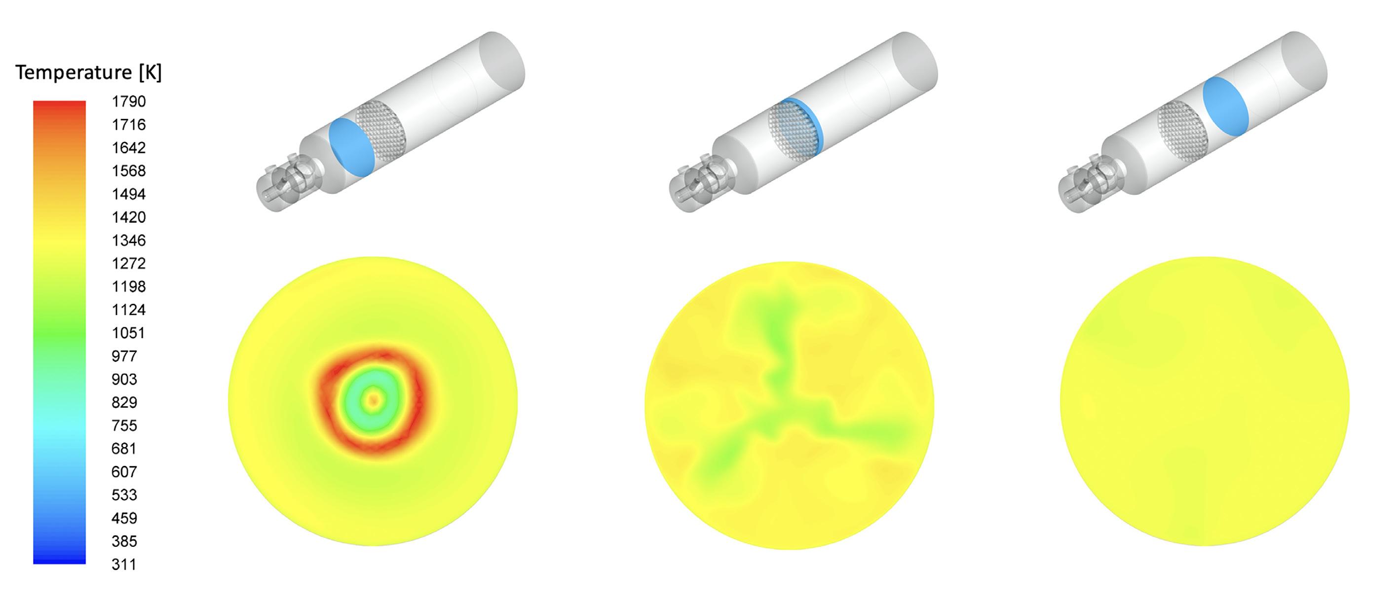
Figure 4. Temperature distribution.

Figure 5. Hydrogen sulfide to sulfur conversion. New waste heat boiler
As with the existing waste heat boiler, the new waste heat boiler was a smoke tube type boiler with the steam drum installed on top, and was supplied by a partner. The engineering focus for the boiler, as well as the design of the heat exchangers, bypass and internal piping, was to keep the pressure drop as low as possible whilst ensuring that the necessary steam generation capacity was met.
Conclusion
Each section of the original equipment – the burner, the reactor and the waste heat boiler – had issues.
Due to construction issues, the burner had undefined mixing of oxidation and Claus gas; the flame stability was poor during start-up and lower load cases; and there was corrosion due to Claus gas condensation. Even though the reactor was equipped with a checkerwall, it had inhomogeneous temperature distribution, hot spots damaging the refractory, and problems with long burner flames, as the checkerwall was positioned near the burner.
The biggest issue with the waste heat boiler was welding cracking, which arose due to thermal stress caused by an inhomogeneous temperature profile.
To meet the client’s requirements – no impairment of process parameters, low-supply pressure on the Claus gas and combustion air side, high hydrogen sulfide to sulfur conversion rate – CS Combustion Solutions took the following measures: n The original burner was replaced with a low-pressure double staged swirl burner to minimise the pressure drop over the burner and ensure proper mixture of Claus gas with oxidator. n A new reactor with the same dimensions as the original one but equipped with a VectorWall with low pressure drop instead of a checkerwall was used. Swirl and turbulence was increased, as the VectorWall generates separate mixing zones for an even distribution across the entire wall. n A new waste heat boiler was specially designed by a partner to keep the pressure drop as low as possible. n Multiple CFD analysis instances were carried out to verify the design and to ensure that the guaranteed hydrogen sulfide to sulfur conversion rate of 65% or above, as well as an increase in the maximum sulfur capacity to 120%, was met.
The result of the retrofit was a completely new thermal process stage consisting of burner, reactor and waste heat boiler for a Claus plant with a sulfur output of 700 tpd.


