
11 minute read
Maintaining sample heat integrity

Rod Merz, AMETEK Process Instruments, Canada, explores the most common analytical heat integrity failure points seen with analysers in sulfur recovery units.
The number one analytical concern with analysers used in a sulfur recovery unit (SRU) is sample heat integrity. Heat integrity is the most common non-electronic related cause of analyser problems in an SRU.
There are several analytical points of interest in a typical SRU and amine-based tail gas treating unit (TGTU). Each analytical point has a unique purpose and unique measurement challenges. The analytical measurement points, as shown in Figure 1, include: the feed forward analyser (AT1), the sulfur pit analyser (AT2), the air demand or tail gas analyser (AT3), the possible gas measurement points within the TGTU (AT4/AT5/AT6), and the thermal oxidiser’s continuous emissions monitoring system (CEMS) analyser (AT7).
Feed forward/acid gas analyser
The feed forward analyser (AT1) is found in a refinery and gas plant SRU where the acid gas concentration may vary, or the hydrocarbon concentration variations from upstream process upsets can cause difficulty in controlling air demand. The acid gas sample stream at this point in the process consists of the main constituents of hydrogen sulfide (H2S), carbon dioxide (CO2), water (H2O) and, to varying degrees and depending on the process, ammonia (NH3), amine, and carried over hydrocarbons. While the acid gas stream is lower in temperature than the rest of the SRU sample stream analytical points, it is always considered ‘saturated’ with H2O. This means that, from the sample take off point to the sample return point, the sample temperature must be kept above the sample’s actual dew point, or the sample will condense. This condensation can cause fouling of optical windows, plugged or percolating sample lines, fouled filters, corrosion, as well as other analytical maintenance issues. An analytical best practice is to operate the sample system and analyser 10 – 20°C or higher than the process
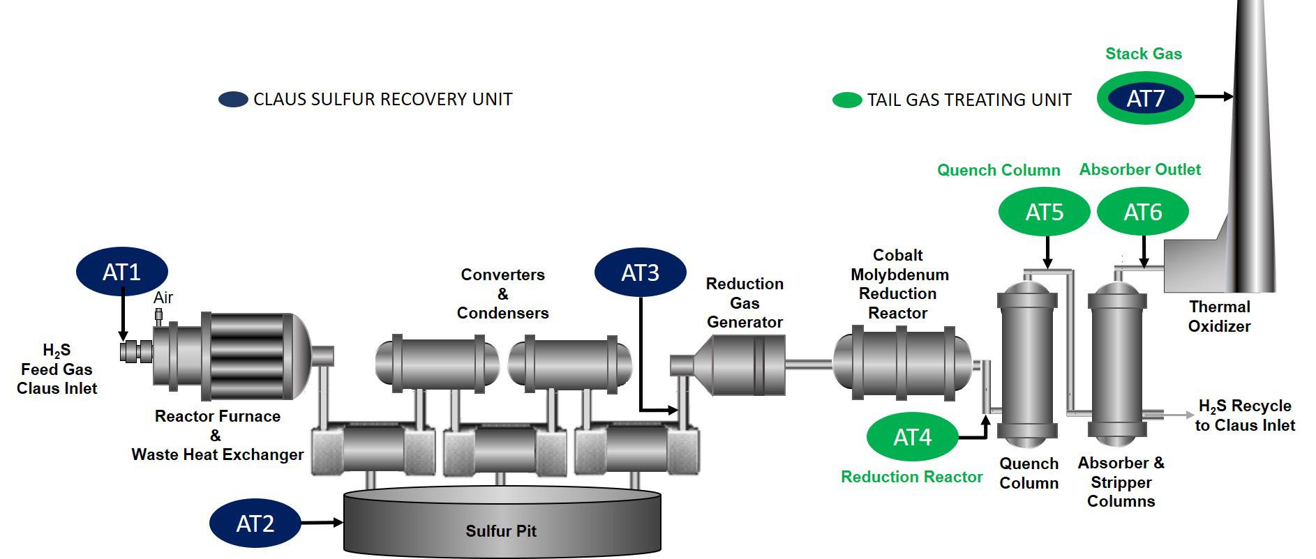
Figure 1. SRU and TGTU analytical points.
sample temperature. As an example, if the acid gas stream is 30°C, the sample probe and sample line, as well as all wetted analyser components, should be at a minimum of no less than 40 – 50°C. In addition, for sour water stripper gas (SWAG), the sample must be maintained 10 – 20°C above the ammonia salt formation point (typically heated to 80 or 90°C). This fine detail is often overlooked by an inexperienced sample system designer who only looks at the sample dew point on the data sheet.
While most installations are designed with good intentions, there are a few common issues that are found in the field. In colder climates, the sample nozzle should be insulated, and if the nozzle is longer than 6 in. (150 mm) off the process pipe, the nozzle should be heated – either jacketed or heat traced. The sample probe should also be insulated and have its own heater built in to maintain it above the sample dew point. Connections between sample system components need to be looked at closely for possible condensation points, including unions between the probe and sample line, transitions into analyser enclosures, and internal analyser connections. All of these are locations where sample condensation can wreak havoc with an analytical measurement.
Air demand/tail gas analysers
The air demand analyser (ADA), also known as the tail gas analyser, and the pit gas analyser can be treated as identical systems since the sample composition and dew points are similar enough. In this analytical application, the most significant problem observed is sulfur coming out of the vapour phase and plugging off the sample handling and analytical components.
From a heat integrity point of view, the ADA is similar to the CEMS unit in that it has the greatest plant impact due to heat integrity issues. With the sample stream temperature from the SRU’s final condenser optimally being only a few degrees above the freezing point of sulfur, any cold spots with the ADA and its sample handling components will lead to the occurrence of solid sulfur deposition, which will inevitably cause the analyser system to plug. The following proactive measures will keep the analytical system in optimal operating condition: Proper insulation of the sample nozzle
The sample nozzle itself is a significant point of risk and a common trouble spot. It must be properly insulated regardless of length. If the sample nozzle is longer than 6 in. (150 mm), it must also be heated (see Figure 2). It is not adequate to try and wrap the nozzle in stainless tubing using steam as the heating medium, with insulation over the top. The actual surface contact point of tubing to nozzle surface is very small, so no useful conduction of heat occurs. Any heat transfer is mostly by radiation and it does not have the efficiency to transfer the heat properly.
Using a steam or glycol jacketing system such as ControTraceTM (Figure 3) or ControHeatTM is one solution. If low or medium pressure steam is the heating medium, it needs to be at the appropriate temperature/pressure and adequately trapped and dry. Wet steam is not going to meet the manufacturer’s temperature design criteria. This tends to be one of the more common problems that service technicians see. A means to quickly determine whether there are nozzle temperature issues is to take a piece of sulfur and scrape it on the surface of the nozzle. It should melt.
Sample line transitions
As mentioned previously regarding the feed forward/acid gas analyser, attention should also be paid to any sample line transitions into enclosures that could be a cold spot to ensure that they are not a point where sulfur deposition could occur.
In addition to cold spots, excess heat can also be problematic for analyser sample lines. ADAs that have high temperature sample lines can have issues if the sample inlet and sample return lines are not properly spaced during installation. In this case, the issue is excess heat buildup where the sample lines are too close and can cause premature failure of the sample line’s heater circuits.
Protection from external elements
The analyser also needs to be protected from prevailing wind, rain and snow. Rain or snow falling on a hot nozzle can quickly
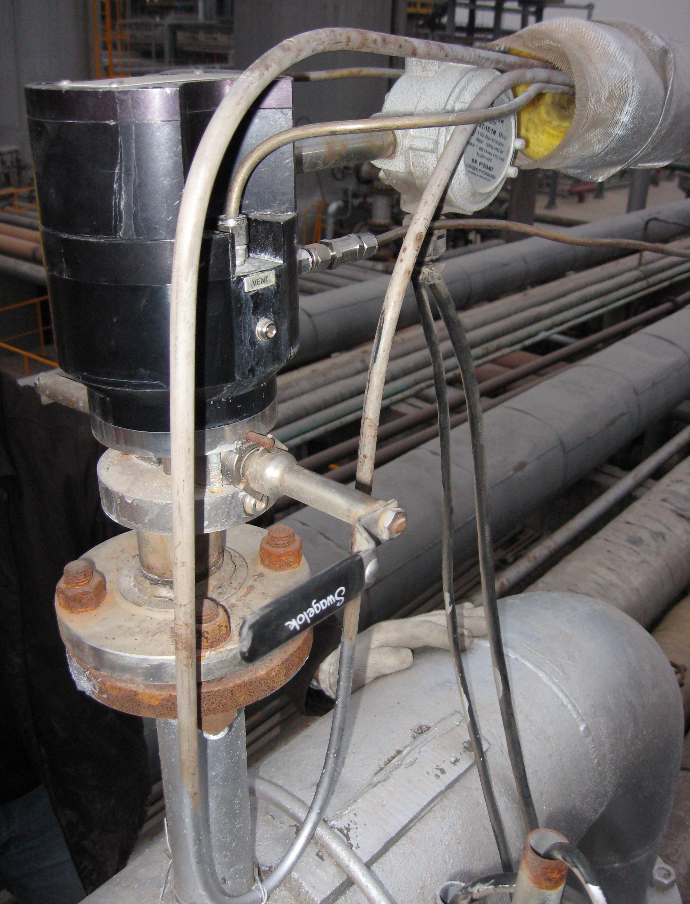
Figure 2. Poor attempt to use steam heated tubing; insulation removed.

Figure 3. ControTrace prior to installation. drop the surface temperature and result in sulfur deposition. A simple three-sided shelter can prevent weather-related problems in temperate climates, but a proper environmentally controlled shelter will be needed in both cold and hot climates. Excess heat is a significant factor in shortening the lifespan of analyser electronics. It is important to ensure that the analyser is protected from direct sun and is in an environment that meets the manufacturer’s specifications for ambient temperature operation.
Amine-based TGTU analysers
Most amine-based TGTUs will only have one of the analyser tags shown in Figure 1 and will be located on either the quench outlet (AT5) or the absorber outlet (AT6). Occasionally, there will be an analyser at the hydrogenation reactor outlet (AT4), but it is typically considered a problematic or compromised sample point in comparison to the other two locations. In general, everything that was discussed with the feed forward analyser or acid gas analyser also applies to this analytical application – the sample gas will be saturated and therefore will require all analyser sample components to be heated to 10 – 20°C above the sample dew point. The only special consideration that is uniquely applicable to the TGTU is the potential to form sulfur in the TGTU analyser probe/filter and plug it off if sulfur dioxide (SO2) has broken through. The residual tail gas H2S can react with the SO2 breakthrough and form sulfur in the analytical system.
If sulfur formation occurs in here, more significant problems will occur with the acidification of the quench water system, plugging of the quench water circuit, and the formation of heat stable salts in the amine absorber.
CEMS analysers
The CEMS analyser (AT7 on Figure 1) is a governmental compliance requirement for SRU SO2 emissions in most jurisdictions. In the majority of countries, there are strict penalties for not meeting emission rules and regulations, so the CEMS analyser should be the most operationally significant analyser and operational downtime must be minimised.
From a heat integrity point of view, the components that need to be considered include: the sample probe, heated sample lines, and the sample conditioning system if the CEMS is considered for cold/dry extractive systems or dilution-based analytical systems.
The most common problem is a result of sulfur trioxide (SO3) concentrations present during SRU upset conditions and the resulting elevation of the acid dew point. SO3 is typically present in concentrations of between 2 – 10% of the SO2 concentrations in SRU incinerator emissions. The SO3 reacts with water molecules and forms sulfuric acid (H2SO4) – a strong acid. When SO3 concentrations are high enough and the acid dew point is reached, the acid forms on surfaces within the sample probe and sample lines. The formation of ‘green slime’ can be physically seen on metal surfaces as this occurs. The green colouration comes from the leaching of chromium and other elements from the stainless steel components into the deposited acid film. The ensuing problems that occur can range from sample system plugging, to a noticeable chromatographic effect where sample and calibration gases diffuse in and out of the slime film in the sample lines, increasing sample response time. Corrosion issues and damage to the analytical sample system are also possibilities.
The CEMS sample probe is where the issues are often centred, and sample lines follow close behind. If the probe requires unusually frequent maintenance, analysis should be carried out on the sample’s acid dew point and the operating temperature of the probe. As indicated above, sample nozzles are notorious for being bad actors, so a probe tube heater may be required to help keep the probe tube’s temperature above the acid dew point. Acid knockout pots and sacrificial filters built into the probe can also be used to mitigate the acid formation in other sample system components such as the sample lines.
The CEMS sample lines can also be a source of temperature issues. Excessive sample line length is often the precursor to heat integrity problems. Depending on both the power supply and sample line manufacturer design, there is a maximum heated sample line length for a single circuit. Where sample line runs exceed a single circuit length, segments of sample line need to be coupled together. This introduces increased risk of losing heat integrity at unions, not to mention the addition of multiple circuit elements for potential failure.
For cold/dry extractive CEMS, the points mentioned above are important and include the sample conditioning system (SCS) located in front of the analyser(s). Heat integrity concerns are usually related to the sample line entry into the SCS and all connections and elements in front of the moisture removal device – usually a Peltier or vortex driven sample cooler. There are otherwise good designs where the heated sample line terminates to an unheated solenoid or valve, which is an excellent point for the sample gas to condense.
Dilution-based CEMS problems typically relate to probe temperature concerns where the orifice may be below the acid dew point, resulting in the formation of acid slime on it. Another concern is during upset conditions where, due to the elevated SO3 concentrations, the acid dew point is still reached even though the system design is supposed to dilute the sample enough to reduce the acid dew point below the system components’ operating temperature.
Hot/wet extractive systems have the benefit of providing an unaltered sample to the analyser but, in this case, everything including the analyser must operate above the acid dew point. All of the identified potential condensation concerns listed above must be considered, and, in situations where SO2 excursions go beyond the normal operating range and are expected, the use of acid knock-out systems at the probe can really help.
Conclusion
This article has focused on the most common analytical heat integrity failure points that are observed in the field. While not discussed, electrical heater failure is also a potential concern; however, typically this is not considered an analytical design failure. The points that have been outlined are not just applicable to SRU and TGTU applications. The principles discussed can be applied to any analyser system on any process. In summary, when looking at the reliability of an SRU analytical system, it is important to consider the following question: where am I at risk of losing analytical heat integrity?
THE FUTURE OF CORROSION PREVENTION
Introducing AMPP, the Association for Materials Protection and Performance. After more than 70 years, NACE International and SSPC have united as the global authority for corrosion prevention knowledge. We are creating the future of materials protection and performance and leading the way for the industries we represent. AMPP members protect people and places around the world from corrosion, and together we are building a safer, protected, and preserved world.

