
8 minute read
Gas recovery


Marco Puglisi, AEREON Europe, Italy, examines applications, equipment and technical solutions for gas recovery packages in the oil and gas sector.
In recent years, the oil and gas industry has been under a lot of pressure from environmental regulatory agencies worldwide to sensibly reduce the emissions of pollutants into the atmosphere. Regulatory attention has been focused not only on the reduction of the emissions of toxic and hazardous substances, but also on the reduction of greenhouse gas emissions – such as methane and carbon dioxide (CO2) – that in the long-term have been proven to have a harmful effect on the environment. The development and installation of gas recovery packages in various upstream, midstream and downstream applications of the oil and gas industry is an initiative in the aforementioned direction. Gas recovery packages are process units aimed at recovering and re-using the gas that would otherwise be either emitted to the atmosphere or thermally destroyed in a flare or thermal oxidiser.
Applications
In the upstream sector, gas recovery units find application in well-head compression facilities. They allow for the continuous and stable production of compressed gas delivered to the sales pipeline, and enhance the life cycle of the well.
The benefits of the installation of a gas recovery unit in a well or group of interconnected wells are evident, as it provides a positive return on investment (ROI) thanks to the economic value of the recovered gas. Moreover, its presence allows for the operation of sites where flaring is restricted or not permitted.
In the midstream sector, gas recovery units are utilised to recover the flash gas that originates from heaters-treaters, phase separators or during crude oil stabilisation process/storage.
Typical examples are the dehydration process of well gas with ethylene glycol, and the light ends (C1, C2) removal from crude oil during the stabilisation process.
In the downstream sector, gas recovery units are typically utilised in refineries or petrochemical plants to recover gas that otherwise would be flared; for this reason, they are called ‘flare gas recovery units’.
A flare is a piece of equipment that is considered as a ‘safety device’ in refineries, petrochemical plants and oil and gas production/transformation sites. It provides safe and effective disposal of toxic and harmful gas during plant emergencies or upset conditions, such as fires, blocked outlets, control valves failures, cooling water failures, electric power failures, instrument air failures or runaway chemical reactions.
A flare produces continuous flaring by collecting and disposing of process gas vented during start-up and shutdown, process transitions, and pressure safety valve (PSV) vents.
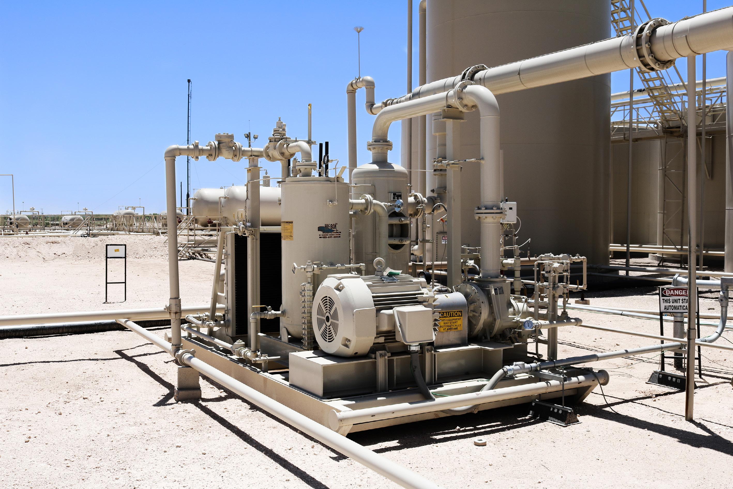
Figure 1. AEREON gas recovery unit in the upstream sector.
Figure 2. AEREON gas recovery unit in the midstream sector.

Continuous flaring not only has the negative effect of increased emission of pollutants, but it also has other disadvantages, such as noise, smell, and visible, smoky flames that can disturb surrounding neighbourhoods. It also increases steam consumption (for steam assisted flares) and electric power consumption (for air assisted flares). As such, a unit that reduces gas flaring and enhances the lifetime of the flare tip is preferable.
Moreover, the recovered flare gas often has a considerable calorific value and can therefore be reused as fuel in the furnaces of the plant or process feedstock, reducing the usage of natural gas or LPG.
Refinery flare gas often contains a sensible concentration of hydrogen sulfide (H2S). Before being reused in the fuel gas network in the furnaces, it must undergo a process of H2S removal through amine absorption. This purification process sets constraints on the minimum pressure at which the recovered gas needs to be available, in the range of 7 – 10 barg.
How it works – compression technology
The principle is similar with all gas recovery units. The flare gas is withdrawn upstream of the liquid seal, compressed through a positive displacement compressor, discharged into the separator, and then routed back to the plant.
The liquid seal maintains a positive pressure on the flare header to prevent air ingress. If the flare gas stream exceeds flare gas recovery system (FGRS) capacity, excess gas will flow to the flare. If the flare gas stream is less, then the FGRS will turndown by staging compressors and/or recycle.
The heart of the unit is the compressor
The compressor is a rotating machine, usually driven by electric power. There are two main families of compressors: positive displacement machines and dynamic machines.
In positive displacement equipment, the gas is compressed at the pressure that is found in the downstream environment, whether it be a pipeline network or a vessel. In this family of machines, the most common technologies applied in a flare gas recovery (FGR) application are outlined below:
Liquid ring
The majority of FGRS installed worldwide are equipped with liquid ring compressors, and it has therefore became a sort of standard for FGR. They can guarantee discharge pressure up to 10 – 12 barg, but their efficiency in the compression process is low (25%).
Sealing of the cylindrical impeller towards the casing (oval) is done with a ring of liquid (seal fluid), usually water, and therefore this machine requires a separator downstream.
The eccentricity between the moving impeller and casing provides the compression of the gas, ensuring a balance of stress and forces.
These compressors are flexible with changes in gas composition, can tolerate presence of particulate, and are reliable and robust if built following the API 681 standard.
Sliding vane
Sliding vanes are mainly used in simple gas recovery packages for upstream and midstream applications. The maximum discharge pressure is approximately 10 barg and they are built with limited turndown. The compression process in these machines is very efficient (approximately 70%), resulting in lower power consumption.
Disadvantages lie in the limited range of material of construction and their inability to follow API manufacturing standard.
Oil flooded screw
These compressors can reach discharge pressures of up to 20 barg; their compression efficiency is higher than that of liquid ring compressors (60%). The main disadvantage is that lubrication oil can come in contact with process gas and may become contaminated if not kept at a high temperature. They are typically found in well-head compression facilities.
Dry screw
These compressors can reach discharge pressures of 10 – 14 barg. The heat of compression remains in the process

Figure 3. AEREON FGR unit with liquid ring compressor.

Figure 4. AEREON FGR unit with liquid ring compressor.
gas and its temperature increases significantly; to keep the process safe and effective, multiple compression stages with intermediate intercooling are required. Variable speed drives (VSD) are used to control the flow and suction pressure; turndown is very high, at 10:1. These machines have high CAPEX.
Reciprocating compressors
Reciprocating compressors are typically not preferred in FGR applications, mainly due to their high maintenance requirements and complexity of construction and assembly. However, their advantage is that they can reach very high discharge pressures of more than 50 barg. They are typically found in the hydrogen network of refineries, where hydrogen needs to be compressed at high pressure in hydrotreating units to remove sulfur.
In dynamic machines, the higher-pressure gas is produced by the dynamic action of the machine itself.
Centrifugal compressors
Centrifugal compressors are dynamic machines. Higher-pressure gas is delivered through a high revolution speed impeller with blades. They are run by VSD, which increases the turndown and optimises power consumption.
They are very efficient and reliable, with a narrow range gas composition (sensitive to surging), and are therefore not suitable for FGR applications. They are found in refineries’ fuel gas and/or hydrogen networks, where gas composition is well defined.
FGR design
The first step in designing a useful and efficient FGR system that is tailored to a customer is to carry out a FEED study. This should evaluate the following points as a minimum: n The existing flare system (liquid seal depth). n Flow metering of the flare gas for an extended period (one month) in two different periods of the year. n Alternative uses for the recovered flare gas. n Flare gas availability (cost). n Flare gas composition range. n Select compressor technology. n System cost/benefit. n Payback time and ROI of the FGR system as a function of the selected capacity vs availability of flare gas determined at flow metering (bullet point 2).
Moreover, the selection of the compressor technology should take into account the following factors: n Process inlet and outlet pressures and temperatures. n Maintenance requirements. n Plot plan availability. n Utilities availability (power, water, steam). n Payback time and ROI as a function of the chosen technology.
Auxiliary equipment to operate the gas recovery unit depends on the selected compressor technology.
For any compressor where service liquid (water or oil) is mixed with the process gas, a separator vessel is required in the outlet line of the compressor. This provides liquid/gas separation and recycle of the gas to keep the suction pressure stable (turndown).
The service liquid takes the heat of compression that needs to be removed. This can be done with an air cooler (axial fans on finned tubes) or a shell and tube heat exchanger, using cold water. In dry screw or reciprocating compressors, the heat of compression is taken by the gas, and interstage cooling is required.
Depending on the compression technology, the gas inlet requirements may vary. For instance, gas must be clean and dry for screw and sliding vane compressors, but this is not critical for liquid ring compressors.
In some cases, knock-out drums or scrubbers may be necessary at suction and discharge of the compressor.
Conclusion
Gas recovery units provide the benefit of conserving resources and reducing emissions by recovering the process vent gas, which often has a considerable heating value. It is a process unit that controls pollution with excellent payback. However, an optimised gas recovery unit design and the selection of the right compression technology for a given application is not a straightforward and easy task; it requires a FEED study that takes into account several intercorrelating factors and should be carried out by qualified and experienced vendors.


