

Maximize your mega-scale blue hydrogen and ammonia production with our SynCOR™ technology. Achieve more than 99% carbon recovery, unmatched efficiency, and the lowest levelized cost of hydrogen. Powered by our industrially proven autothermal reforming, SynCOR is a next-generation technology for today – and tomorrow.
Step into the future with SynCOR today!
03 Comment
04 The evolving landscape of hydrogen in the UK
Conrad Purcell, Shu Shu Wong, Kayley Rousell, and Zainab Al-Qaimi, Haynes Boone, UK, debate the hydrogen landscape in the UK and the steps being taken to increase its development.
09 The hydrogen value chain: scalable pathways to low-carbon production
Aurelia Pipino, Giovanni Genova, and Pietro Moreo, Casale, introduce different pathways for sustainable hydrogen production.
15 Stay on course!
Håkon Volldal, Nel Hydrogen, posits the necessity of hydrogen for a secure energy future that will reap benefits for humanity.
18 Electrolyser evolution
Josef Macherhammer and Dr Alexander Schenk, AVL, Austria, compare different electrolyser technologies, highlighting their market status, efficiency, and operational characteristics.
25 Rethinking materials
Kerry Drake, Le Song, Philippe Alienne, and Pragati Verma, Greene Tweed, explain how cross-linked PEEK materials can play a critical role in advancing components used in hydrogen infrastructure.
31 Turbocharging hydrogen transportation
Reza Agahi and Behrooz Ershaghi, Nikkiso Clean Energy & Industrial Gases, USA, consider the design of turboexpanders in primary and deep cryogenic refrigeration cycles.
37 Enabling the hydrogen shipping revolution
Daniel Patrick, Atlas Copco Gas and Process, USA, considers how centrifugal compressor technology is being scaled to support liquid hydrogen carriers and help manage boil-off gas during transport.
41 Paving a path to zero-loss hydrogen refuelling
Aaron Lapsley, Hyroad Energy, considers how to solve the problem of losses that occur during liquid hydrogen storage and refuelling operations.
45 Unlocking the power of liquid hydrogen
Greg Gosnell, GenH2, USA, discusses why zero-loss liquid hydrogen technology will be key to large scale mobility fuelling.
49 Bridging the gap to mass production of liquid hydrogen
Dr Rajendran Parthipan, Dr Barry Prince, and Dr Neil Glasson, Fabrum, New Zealand, highlight the design, functionality, and applications of small scale hydrogen liquefaction in an industry focused on large scale solutions.
53 Hydrogen safety and detection
Andrzej Janowski, MSA Safety, Poland, discusses the safety considerations, challenges, and technology applications of hydrogen.
58 Advancing the global hydrogen pipeline network
Garry Hanmer, Atmos International, UK, explores some of the challenges facing hydrogen transport through pipelines, and how to implement solutions for safe and reliable operations.
63 Building the nervous system of the hydrogen grid
Suji Kurungodan and Dr Andrew Stevenson, Sustainable Pipelines Ltd, discuss a shift to usher in the net zero era with intelligent, flexible, high-performance pipeline network infrastructure.
CASALE is a global partner in the chemical industry, offering integrated technologies, engineering, contracting, and construction solutions for over a century. Committed to a sustainable, greener future, its unwavering dedication drives the group to innovate, creating solutions that harmonise industry progress with environmental responsibility. The company also offers a wide range of technologies and services in the field of chemical and fertilizer production, including solutions for green ammonia, methanol, hydrogen, and other key components of the Power-to-X value chain.

Halliburton can support your decarbonization journey by delivering cost-effective CO2 and Hydrogen subsurface storage solutions to help meet your organization’s long-term sustainability commitments.
Together, we can engineer the future of energy.

Callum O'Reilly Senior Editor
Managing Editor James Little james.little@palladianpublications.com
Senior Editor Callum O'Reilly callum.oreilly@palladianpublications.com
Deputy Editor Oliver Kleinschmidt oliver.kleinschmidt@palladianpublications.com
Editorial Assistant Willow Munz willow.munz@palladianpublications.com
Editorial Assistant Ellie Brosnan ellie.brosnan@palladianpublications.com
Sales Director Rod Hardy rod.hardy@palladianpublications.com
Sales Manager Chris Atkin chris.atkin@palladianpublications.com
Sales Executive Ella Hopwood ella.hopwood@palladianpublications.com
Production Manager Kyla Waller kyla.waller@palladianpublications.com
Head of Events Louise Cameron louise.cameron@palladianpublications.com
Digital Events Coordinator Merili Jurivete merili.jurivete@palladianpublications.com
Digital Content Coordinator Kristian Ilasko kristian.ilasko@palladianpublications.com
Digital Administrator Nicole Harman-Smith nicole.harman-smith@palladianpublications.com
Junior Video Assistant Amélie Meury-Cashman amelie.meury-cashman@palladianpublications.com
Events Coordinator Chloe Lelliott chloe.lelliott@palladianpublications.com
Admin Manager Laura White laura.white@palladianpublications.com
The latest edition of the International Energy Agency’s (IEA) annual report that tracks hydrogen production and demand worldwide, as well as progress in critical areas such as infrastructure development, trade, policy, regulation, investments and innovation, was released in September 2025.1 The report notes that worldwide hydrogen demand increased to almost 100 million t in 2024, up 2% from 2023. Against this backdrop, it is forecast that low-emissions hydrogen production is set to see robust growth to 2030, though at a slower pace than originally hoped.
The IEA’s analysis of announced projects suggests that low-emissions hydrogen production has the potential to reach 37 million tpy by 2030, down from a potential of 49 million tpy based on projects announced a year earlier. Uptake of low-emissions projects is not meeting expectations set by industry and governments, with growth restrained by high costs, demand and regulatory uncertainty, and slow infrastructure development.
Of course, and as is evidenced by the drop in figures noted above, not all projects that are announced come to fruition, so actual capacity is likely to be significantly lower. Despite this, the IEA expects that projects that are either operational, under construction, or have reached final investment decision (FID) by 2030 will increase fivefold from 2024 levels to more than 4 million tpy, with strong potential for an additional 6 million tpy if effective policies are implemented.
IEA Executive Director, Fatih Birol, said: “The latest data indicates that the growth of new hydrogen technologies is under pressure due to economic headwinds and policy uncertainty, but we still see strong signs that their development is moving ahead globally. To help growth continue, policy makers should maintain support schemes, use the tools they have to foster demand, and expedite the development of necessary infrastructure.”
As Nel Hydrogen explains in an article starting on page 15 of this issue, nothing that is worth doing ever comes easy. The article’s author, Håkon Volldal, uses Thomas Edison and Steve Jobs as examples of pioneers who revolutionised electric lighting and the tech industry, respectively, despite being met with significant challenges and scepticism from peers, the public, and investors. However, both men’s determination and unwavering belief in their vision led them to persevere through the obstacles and transform the way that millions of us live our lives. Volldal says: “Hydrogen engineers and producers are at the forefront of the industry, anyone pursuing hydrogen as a renewable energy source is a pioneer. Yes, there are plenty of challenges in the hydrogen market [...] However, the risk and investment that people and companies are taking will be worth it. Like Thomas Edison, early movers in hydrogen will benefit from a faster learning curve. Like Apple, companies, alongside customers, will reap the benefits of industry leadership and brand loyalty. Most importantly, hydrogen companies will start the movement towards a cleaner world which will have a significant positive impact for the next generation.” Volldal encourages all of our readers to “stay the course” and help pioneer a cleaner future for generations to come.
Editorial/advertisement offices: Palladian Publications
718 999 www.globalhydrogenreview.com
If you are picking up a copy of this issue of Global Hydrogen Review at the Hydrogen Technology World Expo in Hamburg, I’d encourage you to register for a free subscription to the magazine by visiting www.globalhydrogenreview.com/magazine. We’ll also be hosting our annual virtual Global Hydrogen Conference on 3 December 2025. Whether you are able to attend live or would prefer to watch on-demand, you can sign up for a free pass using this QR code.
1. https://www.iea.org/reports/global-hydrogen-review-2025


Conrad Purcell, Shu Shu Wong, Kayley Rousell, and Zainab Al-Qaimi, Haynes Boone, UK, debate the hydrogen landscape in the UK and the steps being taken to increase its development.
Hydrogen, and in particular low-carbon hydrogen, is seen as a key solution for decarbonising various sectors of the UK economy, especially those that are hard to electrify (such as chemical production). However, the hydrogen market is still emerging and faces several challenges, such as high costs, low demand, delays, uncertainty surrounding government hydrogen policy and deployment targets, and infrastructure gaps (particularly relating to transportation and storage). To overcome these barriers and to achieve its ambition of having up to 10 GW of low-carbon hydrogen production capacity by 2030, the UK government has developed a range of policies and support mechanisms, such as the UK Hydrogen Strategy, the Hydrogen Production Business Model (HPBM) and Hydrogen Allocation Rounds (HARs),
the Low Carbon Hydrogen Standard, and the Low Carbon Hydrogen Agreement (LCHA). This article explores the current UK policy and regulatory framework for hydrogen and what it means for the evolving landscape of hydrogen in the UK.
The UK has adopted a dual-ended strategy regarding hydrogen production, supporting both electrolytic and carbon capture and storage-enabled (CCS-enabled) green and blue hydrogen. Electrolytic (green) hydrogen splits water into hydrogen and oxygen using renewably generated electricity; both of which are considered low-carbon if they meet the emission intensity threshold of 20 g CO 2 equivalent (CO 2e)/MJ Lower Heat Values (MJLHV). CCS-enabled (blue) hydrogen is produced when natural gas (methane) is split into hydrogen and carbon dioxide, with the majority of the carbon dioxide produced through the process being captured and stored permanently underground. In pursuit of the government’s goal of establishing a total low-carbon hydrogen capacity of up to 10 GW by 2030, it is anticipated that approximately 6 GW will be sourced from electrolytic hydrogen technologies, and the remaining 4 GW generated by CCS-enabled hydrogen production. As things currently stand, the UK is well on its way to surpassing this ambition, as there is a diverse pipeline of over 100 hydrogen projects, and an aggregate potential capacity of over 15 GW by 2030. These projects span different production methods, end uses, and regions, which demonstrates the adaptability and potential of hydrogen as an energy carrier. The UK has the world’s second largest pipeline of CCS-enabled hydrogen projects, having pledged to invest almost £22 billion in projects in the sector over the next 25 years. The UK also has a strong offshore wind resource, which can provide low-cost renewable electricity for electrolytic hydrogen production, especially in regions with excess generation that otherwise have to resort to curtailment.
There is a need for prioritisation of sectors where hydrogen can have the most impact and competitiveness, such as industrial decarbonisation, heavy transport, and dispatchable low carbon power generation, instead of viewing hydrogen as a single, universal solution. In recognition of this need, the government has developed various policy initiatives and financial support schemes to boost the sector, which include the Hydrogen Strategy 2021, the Industrial Energy Transformation Fund, the Industrial Fuel Switching Competition, the Sustainable Aviation Fuel (SAF) Mandate, the Clean Power 2030 Plan, the HPBM, the Hydrogen Transport Business Model (HTBM), and the Hydrogen Storage Business Model (HSBM), some of which are mentioned in greater detail below. However, the demand for hydrogen is still limited. This is partly due to the lack of a coherent and consistent policy framework across the value chain (both domestically within the UK and as between the UK and Europe), a lack of commitment to deployment targets, the absence of business models for transportation and storage, and the high costs of switching to hydrogen compared
to conventional fuels coupled with a lack of diverse funding options.
With a view to mitigating the commercial, technological, and regulatory uncertainties that the emerging UK hydrogen economy is currently faced with, and to foster the deployment of private capital, the government has launched the HPBM. This is structured as a contract for difference (CfD) under which qualifying producers of low-carbon hydrogen are afforded a guaranteed, fixed strike price based on their production costs and expected returns.
The HPBM is supported by the LCHA, which is a contract between the producers and the Low Carbon Contracts Co., a private limited company owned by the Secretary of State for Energy Security and Net Zero. The HPBM provides revenue support to eligible hydrogen production projects which is critical for them to become financially viable. LCHAs are typically structured as a long-term (15 years) contract using a ‘strike price’ mechanism which enables producers to receive a stable revenue stream. This contractual framework is underpinned by the CfD regime used in the UK renewables sector. CfDs for LCHAs are, however, different from those used for renewables, given that the hydrogen market is less mature compared to the wider renewables market, which in turn has consequential impacts on the risk profile of projects in the sector.
The HPBM is allocated through the HARs, which are competitive auctions for electrolytic hydrogen projects. The first HAR, launched in 2023, resulted in the grant of support contracts to seven successful projects, securing an aggregate capacity of 125 MW and an average strike price of £9.00/kg. The second HAR is expected to award contracts in 2025, having most recently shortlisted 27 electrolytic projects across England, Scotland, and Wales. The shortlisted projects include Harper Lane Hydrogen, a London based project which features a 20 MW electrolyser looking to curb carbon emissions from industrial heating at an asphalt plant, while also providing hydrogen to transportation users across the city; and Selms Muir Hydrogen, a Scottish project in collaboration with European Energy which integrates hydrogen production with a solar energy facility.
The UK government is also developing business models for hydrogen transportation and storage, which are essential to link supply and demand centres, and to provide flexibility and security for the energy system.
Pursuant to its wider decarbonisation strategy, the government has launched the HTBM and the HSBM. Collectively, these aim to offer revenue support and risk mitigation for the development of hydrogen pipelines and storage facilities, respectively. In practical terms, the objective is to have at least two strategically located hydrogen storage facilities (in construction or operation) by 2030. The government is simultaneously exploring the feasibility of repurposing existing gas infrastructure


chartindustries.com howden.com
1. The UK government has launched the HTBM and the HSBM to offer revenue support and risk mitigation for the development of hydrogen pipelines and storage facilities, respectively.
for hydrogen, which has the potential to reduce capital expenditure, shorten delivery times and accelerate market deployment.
Various hydrogen projects are already up and running. Among them is the FutureGrid project, led by National Gas, which tests the feasibility and safety of transporting hydrogen through decommissioned gas transmission assets. The Hydrogen Backbone Link is another notable project. Funded by the Scottish government and industrial partners, it is designing a hydrogen export pipeline to connect Scotland with Europe, tapping into the abundant renewable resources and the growing hydrogen market. Aberdeenshire Council has also recently approved Statera Energy’s Kintore hydrogen project, which will convert surplus Scottish offshore wind power into green hydrogen and, at 500 MW initially scalable to 3 GW, is expected to be the largest project of its type in Europe. Backed by the UK’s £240 million Net Zero Hydrogen Fund and targeted to be operational by 2030, the plant is intended to lower hydrogen production costs, balance the grid, and advance the decarbonisation of hard-to-abate sectors while enhancing national energy security.
The regulatory framework for hydrogen projects in the UK consists of a combination of legislation, government policies and business models. With respect to regulatory bodies in the space, these are made up of a combination of ministerial and non-ministerial departments as well as agencies and other public bodies and relevant local authority (among which are the Department for Energy, Security and Net Zero, the Health and Safety Executive, Ofgem, and the Environment Agency).
Some of the of the key regulations include (but are not limited to):
y Energy Act 2023: this established a regime for the designation of persons in relation to the construction, alteration or operation of a hydrogen pipeline project, and notably extended the licensing permissions under the Gas Act 1986 to include licences for the transmission
and distribution of hydrogen and those arranging the supply of hydrogen will require a gas shipper licence. The Energy Act 2023 also details powers to establish a hydrogen levy which would provide funding for a hydrogen business model. This will be introduced through the Gas Shipper Obligation, which will require gas shippers in Great Britain and Northern Ireland to pay a levy to fund hydrogen business models and related costs, likely increasing gas prices for consumers and necessitating a flexible, sustainable funding mechanism.
y Environmental Permitting (England and Wales) Regulations 2016, SI 2016/1154: this stipulates that any operator wishing to produce blue hydrogen must obtain an environmental permit to do so.
y Infrastructure Planning (Environmental Impact Assessment) Regulations 2017, SI 2017/572: this requires an environmental impact assessment to be undertaken as a part of the procedure for seeking consent in relation to most nationally significant infrastructure projects (NSIPs).
y Planning (Hazardous Substances) Regulations 2015 (SI 2015/627): this regulates the storage of hydrogen, including the introduction of a requirement for consent to be obtained to store 2 t or more of hydrogen.
y Planning Act 2008: this introduced a system of development consent for NSIPs through development consent orders, which combines the grant of planning permission with a range of other consents and provide a package of rights, powers and consents designed to streamline the construction and operation of NSIPs.
While not an exhaustive list, the combination of the legislation listed above makes up the cornerstone of the industry’s regulation. However, other key regulatory areas such as noise, vibration, air, construction, waste, and transport must also be taken into account when contemplating any hydrogen project.
Having made significant strides in laying the groundwork for a hydrogen economy, the UK has a major opportunity to become a leader within this economy. This is both with respect to the production and export of low-carbon hydrogen molecules, in addition to the provision of the products, skills, and services that are needed to grow the hydrogen sector. While the recent Hydrogen Allocation Round 2 shortlist is a positive step forward, further efforts are needed to overcome the challenges and accelerate development. The UK’s innovative ecosystem can also drive cost reductions and efficiency improvements in hydrogen technologies. By leveraging its existing trade partnerships with other countries, such as Germany, Chile, and Australia, the UK can gain access to new markets. However, to realise this opportunity, the UK needs to maintain its policy and funding momentum, provide long-term clarity and consistency, and encourage collaboration and coordination across the entire value chain and the wider energy network.

Aurelia Pipino, Giovanni Genova, and Pietro Moreo, Casale, introduce different pathways for sustainable hydrogen production.
Hydrogen is increasingly recognised as a cornerstone of the global energy transition. Its versatility as a clean fuel and a feedstock for chemical and petrochemical industries positions it as a critical enabler in decarbonising hard-to-abate sectors.
As industries transition toward cleaner energy sources, the demand for high-purity hydrogen is
accelerating – particularly in sectors that are difficult to decarbonise due to their reliance on high-temperature processes and heavy fuel consumption. These sectors are expected to drive the development of large scale blue hydrogen facilities.
For this reason, blue hydrogen – generated from hydrocarbon feedstocks with integrated carbon capture and storage (CCS) – has gained significant attention.
It offers a pragmatic pathway to cleaner energy by leveraging existing infrastructure while minimising carbon emissions.
Meanwhile, green hydrogen, produced through water electrolysis powered by renewable electricity, offers a carbon-free alternative without the need for carbon dioxide (CO 2 ) capture. However, challenges related to cost and scalability currently limit its widespread adoption.
In this context, blue hydrogen emerges as a practical and scalable solution for meeting near-term energy transition goals while green hydrogen technologies continue to evolve.
Several blue hydrogen technologies have been explored, including steam methane reforming (SMR), autothermal reforming (ATR), and partial oxidation (POX) reforming. All these methods rely on CO 2 capture (pre-combustion and/or post-combustion) and permanent storage to achieve low-emission profiles.
Among the most widely employed production methods, SMR remains the leader in terms of production volumes and is considered the most established technology. This process converts fossil feedstocks like natural gas into high-purity hydrogen, with single-train configurations often exceeding 250 000 Nm 3 /h.
By adopting an adequate carbon capture strategy or utilising bio-feedstocks, SMR technology provides a highly effective and economically viable path toward a sustainable alternative, aligning with modern classifications for ‘blue’ and ‘bio’ hydrogen.
In parallel, ATR is the preferred choice for large to mega scale applications, such as the ‘jumbo’ production of ammonia and methanol, due to its excellent efficiency and ability to handle massive production volumes in a single unit.
ATR achieves higher production in single train and higher conversion rates by partially combusting feedstock with oxygen at elevated temperatures. The ATR-based process has lower carbon emissions, and it can count on single pre-combustion carbon capture to achieve higher level of decarbonisation (> 99+%).
POX, a non-catalytic process using pure oxygen, is also utilised for specific H 2 /CO ratios or pure CO production. These processes are often followed by water-gas shift and CO 2 removal stages.
Ultimately, the hydrogen value chain is evolving to support both blue and green pathways. Blue hydrogen leverages fossil resources with CCS, while green hydrogen – produced via electrolysis powered by renewables – offers a zero-emission alternative. Together, these technologies form the backbone of sustainable hydrogen production, enabling a robust and scalable transition to low-carbon industrial ecosystems.
Ammonia cracking completes the hydrogen value chain technology overview. This technology enables flexible, low-carbon transport and reconversion of hydrogen from ammonia for global applications.
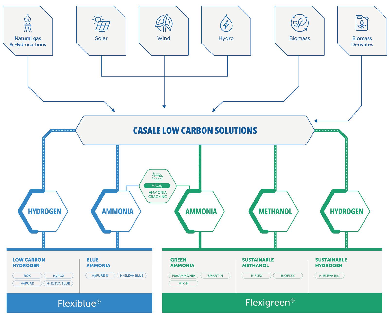
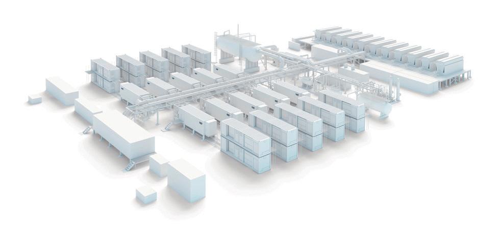
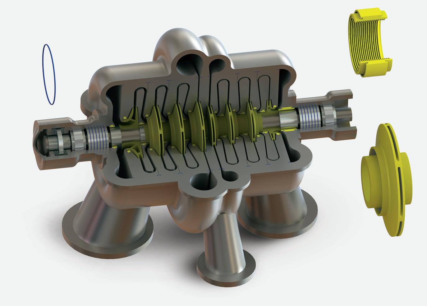
Among these technologies, Casale offers a range of products that can be tailored to customer needs in terms of capacity, decarbonisation strategy, and investments (Figure 1).
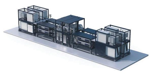
A mature and cost-effective technology that can help to bridge the gap between grey and green hydrogen is Casale’s H-ELEVA-BLUE, which combines proprietary SMR technology with an efficient and seamlessly integrated carbon capture strategy, tailored to specific project targets (Figure 2).
Suitable to accommodate a wide range of feedstocks, from natural gas up to heavy liquid hydrocarbons, and support multi-feedstock design and operations, the technology delivers a versatile and scalable process from very small to large capacities (exceeding 250 000 Nm 3 /h in a single line).
The process can achieve a CO 2 removal rate of up to 95 - 98%+ and can be scaled to customers’ needs. It can also be easily applied to existing conventional grey hydrogen or syngas plants, making it suitable for converting them into blue hydrogen production assets.
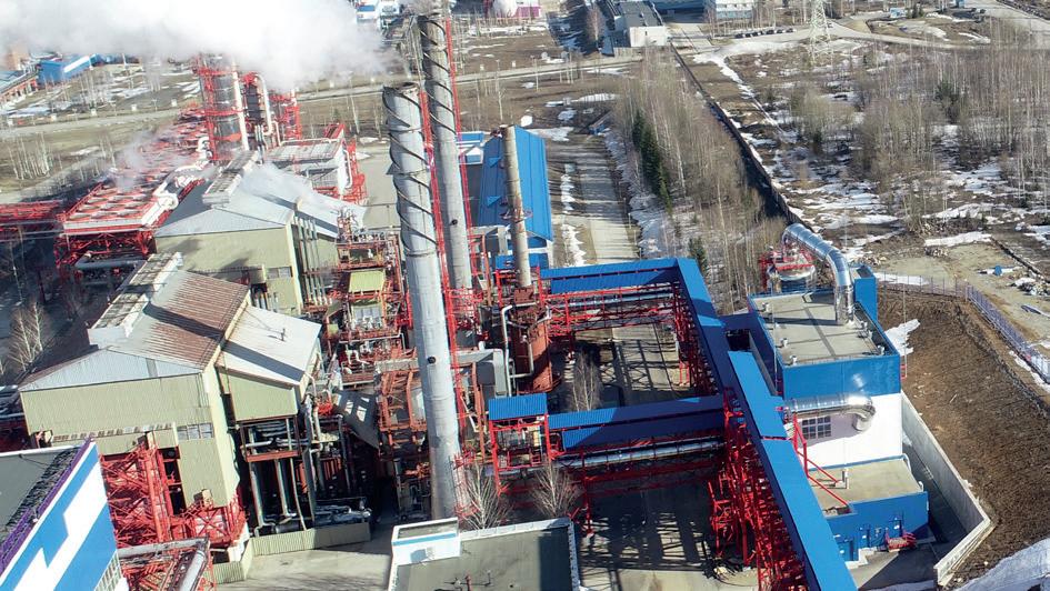
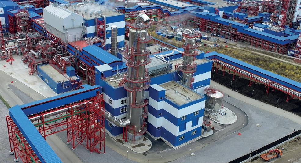
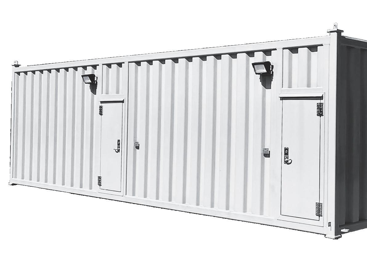
Casale’s recent, successful large scale implementation of the technology involved a customised seamless integration of a single common carbon dioxide removal (CDR) system with two existing,
independent SMR lines (Figure 3). This system captures 1200 tpd of CO 2 from reformer flue gas with a capture rate exceeding 90%.
Casale’s H-ELEVA-BIO offers direct hydrogen generation from biomass-derived sources, empowering the shift towards a robust, circular economy (Figure 4). With this solution, proprietary SMR technology is adapted and enhanced for bio-hydrocarbon feedstocks to deliver cost-effective, sustainable bio-hydrogen.
Production can be optimised across diverse capacities, from small to large scale operations, powered by renewable inputs.
H-ELEVA-BIO offers optional integration with advanced carbon capture solutions. By capturing biogenic CO 2 emissions, it can actively achieve carbon-negative hydrogen production (BECCS).
It is also possible to apply the solution to existing SMR facilities to convert a conventional grey hydrogen production plant to a bio-hydrogen plant, promoting sustainable production with minimised brownfield
execution risks and maximised utilisation.
Casale’s solution enables the production of bio-hydrogen at a rate exceeding 250 000 Nm 3 /h within a single, streamlined train.
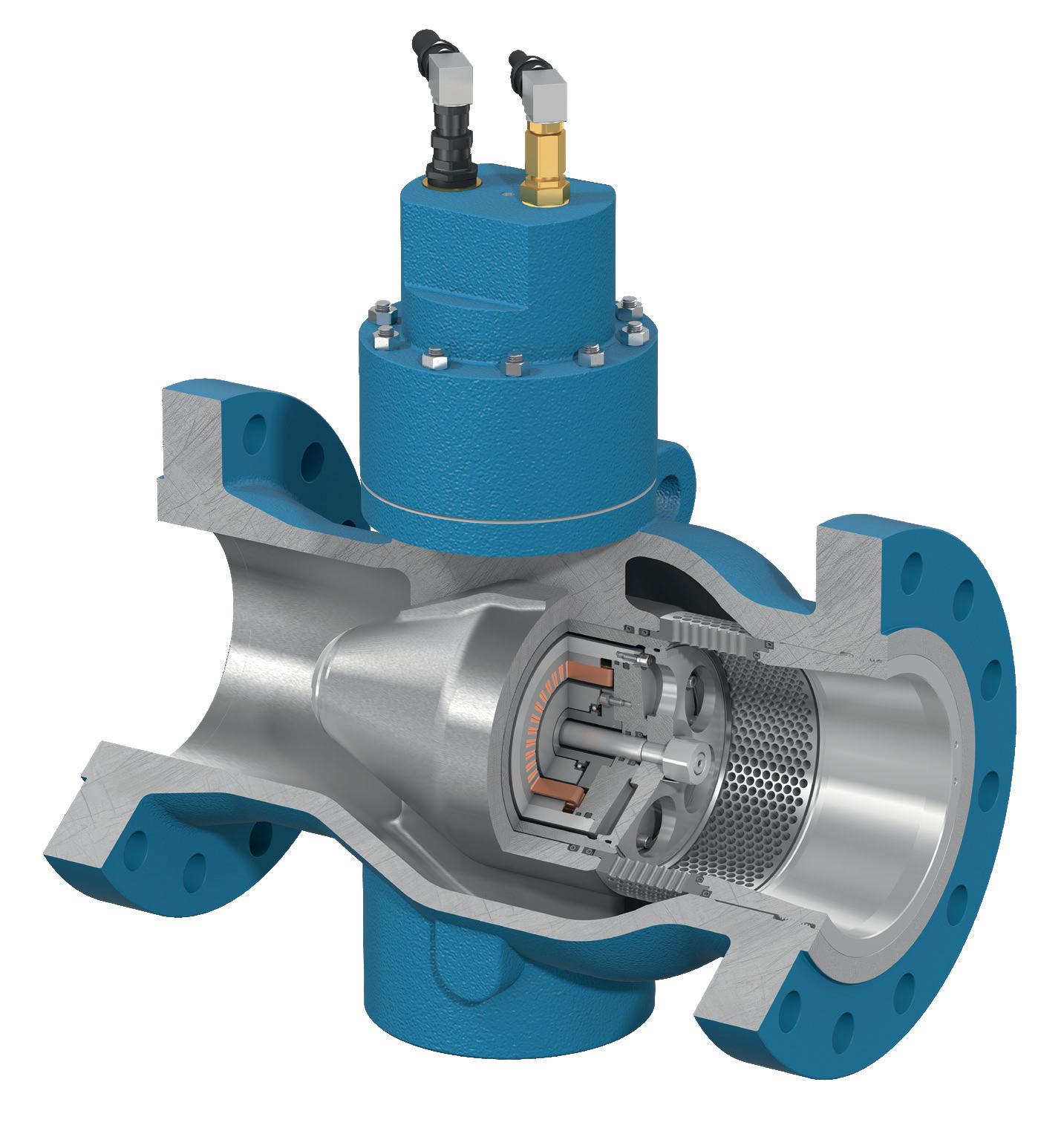
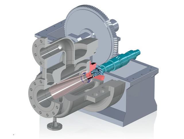
A new solution for blue hydrogen production that merges Casale’s proprietary autothermal reforming (ATR) with Technip Energies’ Recuperative Reforming (TPR®) technology is ROX™ (Figure 5). This technology enables customisation based on hydrogen purity requirements, carbon capture targets, and export specifications. Designed with or without steam export, the system is optimised for seamless integration with downstream units and diverse end-product pathways. It delivers proven ATR-based hydrogen production at scales exceeding 600 000 Nm 3 /h in a single train. The ATR reactor consists of a refractory-lined pressure vessel constructed from low-alloy steel, designed to withstand high pressures and temperatures. At the top of the vessel, Casale’s proprietary water-cooled burner initiates the reforming process by mixing oxygen and fuel to generate a stable, compact flame (Figure 6). This flame is carefully controlled to minimise temperature gradients and pressure drops, ensuring optimal conditions for downstream catalytic reactions.
TPR® enhances the process by recovering waste heat, significantly reducing oxygen, fuel gas, and power consumption. This lowers operational costs and minimises plant footprint and CAPEX.
ROX™ is offered as a comprehensive license that encompasses all key components of blue hydrogen production: air separation units (ASUs), carbon capture systems, and product conditioning – including purification, drying, and compression. It can be deployed as a greenfield solution or retrofitted into existing facilities. For projects with specific logistical or regional constraints, the modularised ROX™ variant offers a streamlined construction approach, reducing on-site risks and improving schedule certainty.
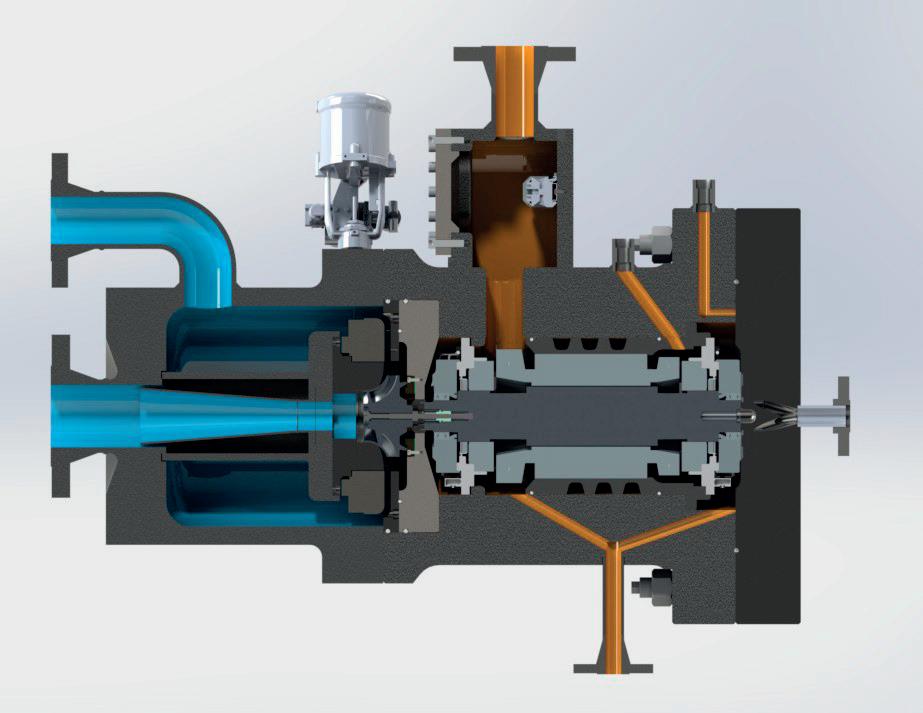
Casale’s non-catalytic POX technology, first deployed in 1998, is built around a robust water-cooled burner design. Operating pressures in current installations reach

up to 30 bar, though the technology is capable of handling higher pressures (Figure 7).
At the core of the POX system is a specially engineered burner housed within a refractory-lined pressure vessel known as the gas generator. Fuel and oxygen are introduced separately through the burner, creating a diffusion flame upon contact. The burner assembly, constructed from austenitic stainless steel, includes an oxygen lance and is designed to withstand intense thermal stress. All flame-exposed surfaces are actively cooled using demineralised water, ensuring durability and safe long-term operation.
The HyPOX process developed by Casale integrates POX with an isothermal water-gas shift reaction, followed by CO 2 removal and hydrogen purification. With optimised carbon capture strategies, the process can achieve up to 99% CO 2 removal.
One of the latest implementations of the technology has demonstrated hydrogen output of 50 000 Nm 3 /h, equivalent to a 600 tpd ammonia plant.
Casale’s proprietary ammonia cracking process, MACH2™, offers sustainable, large scale production of hydrogen, enabling the flexible, long-distance transport of both blue and green hydrogen via ammonia (Figure 8)
Suitable for both blue and green production pathways, the system is designed to fit a wide plant capacity range, offering a single-train capacity exceeding 1300 tpd of
hydrogen (equivalent to 9360 tpd of ammonia feedstock). This process delivers pure hydrogen, up to Grade 5.
The process scheme is built for simplicity and efficiency, and allows for customisation and optimisation to meet a client’s specific project needs, such as using an external fuel source, meeting steam export requirements, or integrating for power generation and cogeneration.
At the core of the process is the ammonia cracking unit, an SMR-based system capable of effectively decomposing ammonia into high-pressure hydrogen on a large scale. The product can then be further purified in a dedicated purification section to achieve the required purity level.
The technology delivers hydrogen up to 40 barg without the need for any dedicated compressor and without producing any steam export.
Developed in close collaboration with world-leading catalyst manufacturers, MACH2™ offers an agnostic design suitable for a validated range of catalyst suppliers.
The hydrogen value chain demonstrates a pragmatic and multifaceted approach to the global energy transition. A diverse portfolio of technologies can help to provide a clear pathway for industries to achieve their decarbonisation goals.
The future of hydrogen lies in its adaptability. Casale’s commitment to providing a spectrum of solutions, whether through its Flexiblue® or Flexigreen® pathways, ensures that hydrogen can drive the decarbonisation of key sectors and support a resilient, low-carbon future.

Håkon Volldal, Nel Hydrogen, posits the necessity of hydrogen for a secure energy future that will reap benefits for humanity.
billions of people will continue to live in poverty. Cutting emissions by reducing activity is not a viable pathway either, if businesses want their industries to continue to thrive.
The third pathway is to do everything that can be done to bring about clean and abundant energy for all. The goal is to make it possible to consume as much energy as is needed to live comfortably, even luxuriously, but to be able to do so with a clear conscience. To accomplish this, it is going to take significantly more renewable energy than is currently available. According to the International Energy Agency (IEA), nearly 90% of global electricity generation will need to come from renewable sources by 2050 in order to reach net zero emissions.


Humanity needs clean hydrogen in the mix of renewable resources, because it cannot simply electrify all industries. How much hydrogen would be needed in the mix? 10, 15, 20%? It is difficult to know the exact answer, but hydrogen will play a vital role in decarbonisation. It is highly versatile, in that it is transportable; it can be made inexpensively, and then transported to where it is needed and consumed. But one of the key benefits of hydrogen that makes it stand out is that it is the only way to stabilise energy systems for longer periods of time. In the future there will be much more renewable power coming into the grid, and this influx will generate enormous price fluctuations. Hydrogen can help to stabilise those vacillations, acting as a buffer in the energy system, and stabilising energy bills for businesses and homes alike.
The fundamental arguments for hydrogen are strong, but missing pieces must be found before substantial progress can be made. Beginning with the human factor: boldness is needed, as are first movers, and even mistakes. As Albert Einstein once said: “Anyone who has never made a mistake has never tried anything new,” and in order to change the world, new solutions are needed.
Consider Thomas Edison, a first mover in electric lighting and innovation. Was that a smooth journey? No. Edison faced significant obstacles, from relentless experimentation and repeated failures, to scepticism from the public and investors who doubted that electric lighting could replace gas lamps. Yet Edison persevered, committed to taking risks in pursuit of his vision. His bold determination allowed him to develop practical electric lighting and numerous other inventions, making him synonymous with innovation, persistence, and transformational change in everyday life.
Steve Jobs revolutionised the tech industry by envisioning a new future for personal computing – and, crucially, never giving up on his vision. Was that an easy undertaking? No. He met serious challenges. Early programs were commercial failures that lead to financial strain. He had to grapple with management conflicts. He even had to leave his own company at one point because people did not want to work with him. Jobs had to overcome massive technological burdens that prevented him from realising the programmes that he wanted to put to market. But despite the risks, despite the setbacks, he never gave up, and now Jobs is hailed as one of the greatest business leaders of all time.
Hydrogen engineers and producers are at the forefront of the industry, anyone pursuing hydrogen as a renewable energy source is a pioneer. Yes, there are plenty of challenges in the hydrogen market; there is a lack of clarity on regulations and framework conditions; there are higher interest rates, tighter capital markets, cost escalations, and installation projects take a long time to mature. However, the risk and investment that people and companies are taking will be worth it. Like Thomas Edison, early movers in hydrogen will benefit from a faster learning curve. Like Apple, companies, alongside customers, will reap the benefits of industry leadership and brand loyalty. Most importantly, hydrogen companies will start the movement towards a cleaner world which will have a significant positive impact for the next generation. Stay the course.
But solutions are needed to make hydrogen viable at scale. Companies need to make renewable hydrogen easy and ask, ‘what is the best way to do that?’
Nel has built electrolysers since 1927, and offers some of the most reliable and energy-efficient products in the world. For those who would like to start projects today, there are solutions. There is technology that has been tested and proven in the field and is ready for the green energy era. However, today’s solutions are not good enough to unlock the full potential of hydrogen. Companies must gain more knowledge, reduce cost, and increase efficiency. Nel has begun that work, and companies must do that work step by step as they continue to dream big.
New products should change the hydrogen industry. New, next-generation electrolyser systems should be far less expensive and far more energy efficient than anything currently available: new pressurised alkaline and PEM electrolyser systems should have revolutionary cell stacks and system designs. They should be based on standardised, pre-fabricated modules that are designed to minimise the need for engineering work, reduce footprint, and make physical buildings redundant. Installation and commissioning will be simplified, and thus the total project CAPEX decreases significantly. Analysts predict that the industry will reach certain cost levels by 2045 or 2050, but the more advanced technology should get companies there in just a few years.
New enabling technologies could reduce the cost of producing hydrogen to a level where customers will be in a position to pursue many more projects and make those projects viable both for them and their off takers.
By choosing to stay the hydrogen course, companies can embrace with both hands a world in which they are not
beholden to fossil fuels. They can shape a cleaner future for subsequent generations, without sacrificing the quality of life of the current one. The time has come to decarbonise the planet, together.
When uptime, safety and durability can’t be compromised, Hunter buildings are up to the task. Hunter’s custom modular steel structures are designed to endure — and perform — under pressure. Reliable, rapid and purpose-built for industrial resilience, Hunter has you covered on every front

Occupied Structures
Control Rooms, Operator Shelters, Lab Buildings, Guard Shacks & Accommodations
Critical Equipment Structures
Remote Instrument Enclosures, E-Houses, BESS, Data Centers & Substations
Protective Designs Available Blast Resistant, Forced Entry/Ballistic Resistant, Catastrophic Weather Shelters & Toxic Ingress Protection

Josef Macherhammer and Dr Alexander Schenk, AVL, Austria, compare different electrolyser technologies, highlighting their market status, efficiency, and operational characteristics.

The transition towards a sustainable energy future hinges on large scale production of green hydrogen.
Electrolysers, which split water into hydrogen and oxygen using electricity, are central to this process. This article explores the evolution of electrolyser technologies, focusing on proton exchange membrane (PEM), anion exchange membrane (AEM), and solid oxide electrolysers (SOECs). Their market status, efficiency, operational characteristics, and the latest innovations driving the development will be discussed.
The electrolyser market is rapidly evolving, driven by the global push towards decarbonisation and the increasing demand for clean energy solutions. As of 2024, the global electrolyser market was valued at approximately US$8.9 billion and is projected to grow at a compound annual growth rate (CAGR) of 44.2% from 2025 to 2034.1 This growth is fuelled by favourable government policies, financial incentives, and the falling costs of renewable energy sources.
Alkaline electrolysers (AEL) currently dominate the market due to their low cost and long operational life. PEM electrolysers are gaining traction for their high efficiency and compact design, suitable for dynamic operations. SOECs are emerging as a high-efficiency option, particularly for industrial scale applications, while AEM electrolysers are still in the developmental stage, but potentially hold promise for combining the advantages of both AEL and PEM technologies.2
Each electrolyser technology has unique features, advantages, and challenges that impact their suitability for different applications.
y Features: operate using an alkaline solution (e.g., potassium hydroxide) to facilitate the electrolysis process. They typically function at lower current densities and temperatures compared to PEM and SOEC technologies.
y Advantages: mature technology with low capital costs and long operational life. They do not require precious metals, making them cost-effective for large scale industrial applications.
y Challenges: slower response times and lower efficiency compared to PEM and SOEC electrolysers. The need for concentrated alkaline solutions can lead to corrosion issues.
y Features: operate at low temperatures (50 - 80°C), high current densities, and offer rapid response times.
y Advantages: high efficiency, compact design, and high-purity hydrogen production.
y Challenges: high capital costs due to the use of precious metals like platinum and iridium.
y Features: operate at low temperatures, use non-precious metal catalysts, and have a simpler balance of plant (BoP).
y Advantages: lower material costs and potential for high efficiency.

y Challenges: durability and long-term stability need improvement to match PEM and SOEC technologies.
y Features: operate at high temperatures (500 - 1000°C), enabling direct electrolysis of steam.
y Advantages: high efficiency and the ability to utilise waste heat from industrial processes.
y Challenges: high operating temperatures require robust materials and advanced thermal management.
For SOEC and AEM technologies to become reliable and ready for industrial applications, several key requirements must be met:
y Material durability: development of materials that can withstand high temperatures and corrosive environments.
y Thermal management: efficient thermal management systems to handle high operating temperatures.
y System integration: integration with industrial processes to utilise waste heat and improve overall efficiency.
y Membrane stability: improvement in membrane stability and longevity under operational conditions.
y Catalyst development: development of non-precious metal catalysts that offer high activity and durability.
y Scalability: demonstration of scalability and reliability in large scale applications.
Recent advancements in electrolyser technologies are paving the way for more efficient and cost-effective hydrogen production.
y Catalyst optimisation: development of catalysts with reduced precious metal content while maintaining high activity.
y Membrane improvements: advances in membrane materials to enhance durability and performance.
y Manufacturing techniques: improved manufacturing processes to reduce costs and increase production scale.
y Membrane technology: development of advanced AEMs with higher ionic conductivity and stability.
y System design: innovations in system design to improve efficiency and reduce operational costs.
y Pilot projects: successful projects demonstrating the viability of AEM technology in real-world applications.
y Material science: advances in high-temperature materials to improve durability and performance.
y System integration: integration with renewable energy sources and industrial processes to enhance overall efficiency.
y Commercial deployments: early commercial deployments showcasing the potential of SOEC technology for large scale hydrogen production.
To illustrate the potential of these technologies, this article will now explore practical examples of PEM, AEM, and SOEC systems.
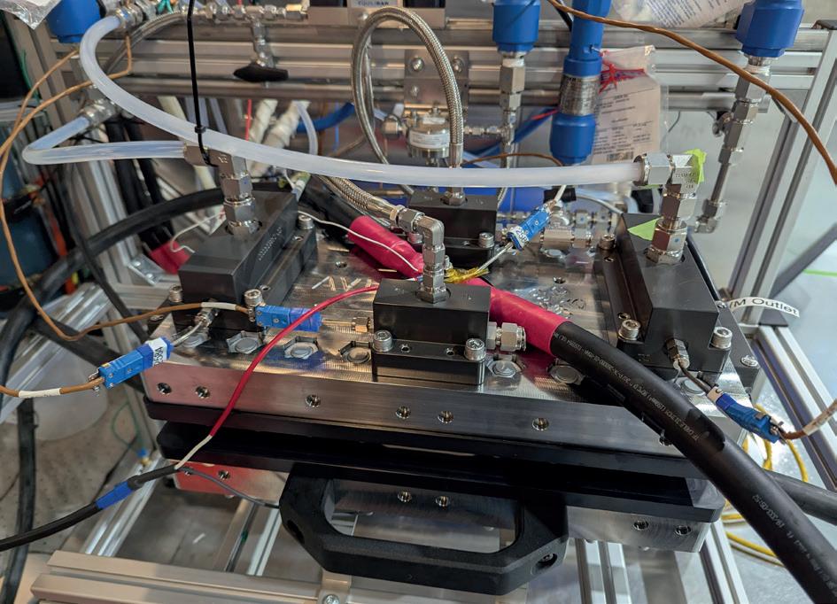
AVL has recently expanded its hydrogen technology portfolio to include PEM electrolyser stacks, leveraging its experience in fuel cell development and automotive engineering. In 2024, the company designed, built, and tested its inaugural PEM electrolyser stack, designated as AEE 1, within a 12-month timeframe (see Figure 1). This stack operates at a differential pressure of 30 bar and achieves an efficiency exceeding the US Department of Energy’s (DOE) 2026 target, delivering 71% lower heating value (LHV) efficiency, equivalent to 47 kWh/kg of hydrogen produced.
AVL’s background in high-volume automotive fuel cell stack engineering provided a solid foundation for the development of the AEE 1 electrolyser stack by applying proven design principles and manufacturing techniques to the electrolyser domain, facilitating rapid development and optimisation of the stack’s performance characteristics.
Selecting appropriate materials for stack components, including membranes, catalysts, and bipolar plates, ensured durability and performance under high-pressure operation (30 bar differential pressure). The careful design of the stack architecture facilitated efficient gas and water management, minimising losses and enhancing overall efficiency.
Figure 2 illustrates the performance benchmark of the AVL AEE 1 PEM electrolyser stack in terms of efficiency (expressed as %LHV) against current commercial stack designs and the US DOE’s established targets for 2026 and ultimate goals. The AVL AEE 1 stack is denoted by blue data points, showcasing its efficiency across a range of current densities. Notably, the stack consistently operates above the DOE’s 2026 target efficiency of 67% LHV, achieving 71% LHV efficiency (47.6 kWh/kg hydrogen). This is a substantial performance improvement when compared to typical commercial stacks, represented by red cross markers within the yellow-shaded region.
AEM electrolysis is attracting significant attention due to its potential to combine the key benefits of both PEM and alkaline electrolysis. Unlike PEM, AEM systems do not rely on precious metals for catalysis, significantly reducing costs while maintaining competitive efficiency. Additionally, AEM electrolysers operate in alkaline conditions, which broadens the range of available materials and lowers corrosion rates, enhancing durability. Moreover, AEM technology allows for flexible operation and easier handling of electrolyte management compared to traditional alkaline systems. With the advancements in membrane technology, AEM electrolysers are expected to close the efficiency gap with PEM while surpassing alkaline technologies in terms of cost-effectiveness and sustainability.
The AEE 1 PEM electrolyser stack provides a foundation for exploring its adaptation towards AEM electrolysis. By leveraging PEM stack design and digital simulation, AVL investigates the

At TDW, we believe pipeline operations and environmental sustainability go hand in hand. Our hot tapping and isolation services allow operators to safely modify and maintain pressurized systems, without venting or blowdown.
That means critical work can happen without releasing methane, helping operators meet emissions targets and reduce environmental impact without compromising operations.
Because at TDW, emission reduction isn’t a future vision, it’s what we deliver every day. And we’ve been doing it for decades.
Explore how TDW enables emissions reduction.
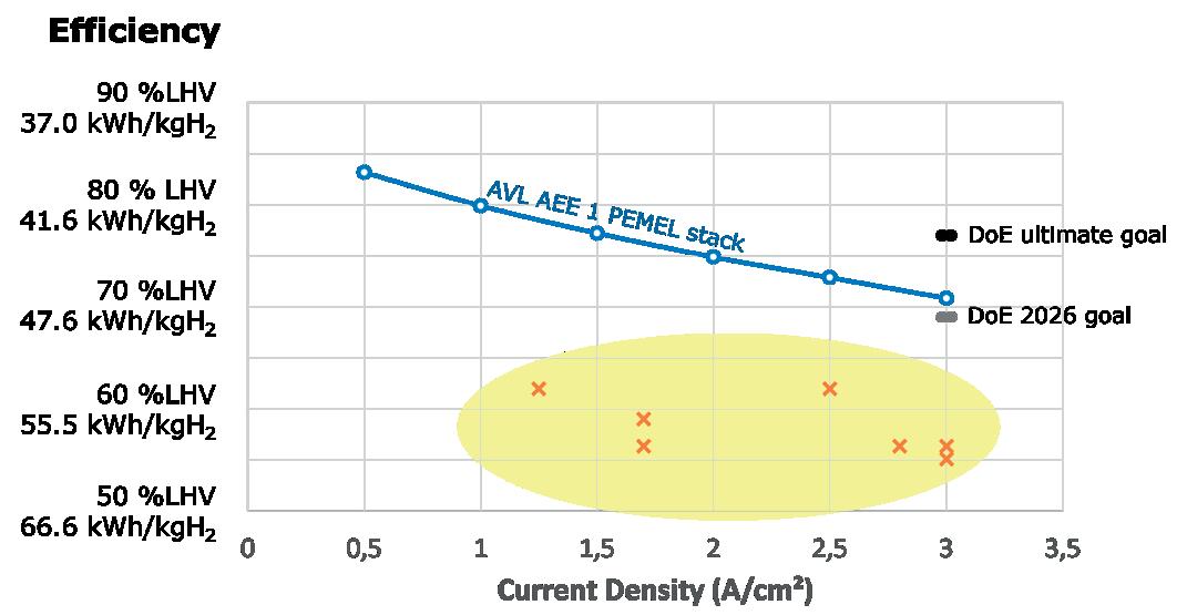
Figure 2. Benchmark comparison of AVL AEE-1 PEM electrolyser stack efficiency against US Department of Energy’s (DOE) targets and market competitors.
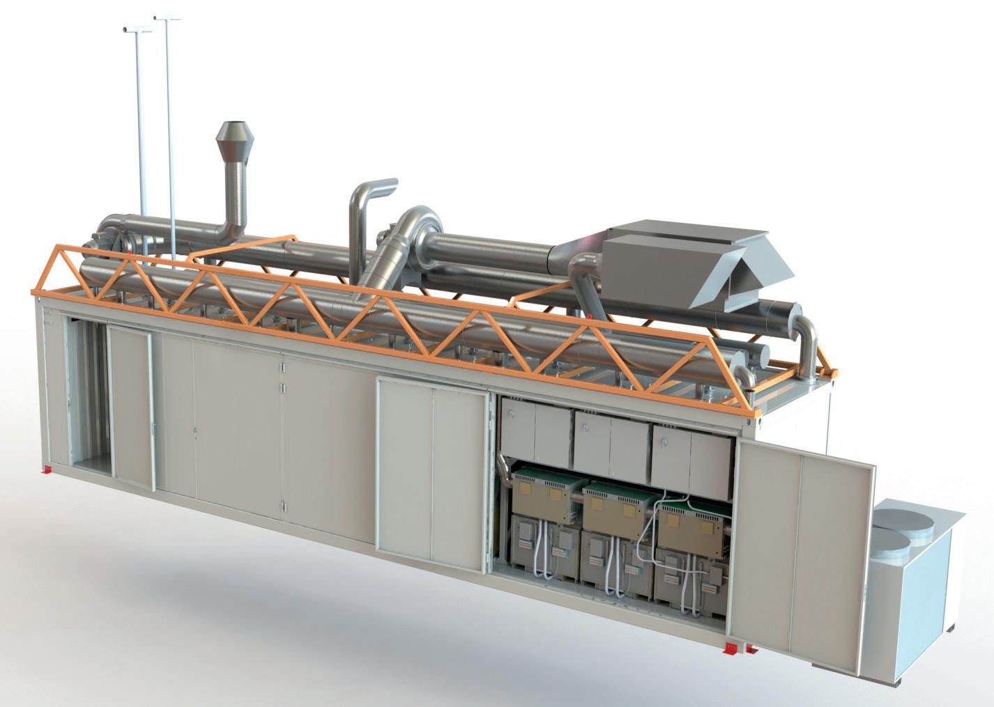
Figure 3. AVL 1 MW solid oxide electrolysers (SOEC) container solution.
transitioning of the AEE 1 stack design to AEM electrolysis and the corresponding necessary strategic modifications. The new AEM electrolyser stack, denoted AEM 1, targets a capacity of 500 kW, capable of producing 225 kg/d of hydrogen. Performance targets for this development are set based on existing supplier data, focusing on key metrics including an efficiency of 63% LHV, an energy consumption of 53.2 kWh/kg hydrogen, and an operating pressure of 30 bar. Since the US DOE’s long-term targets are not available yet, AVL’s targets are strategically aligned with IRENA’s 2020 benchmarks for green hydrogen production.
AVL has also been actively advancing its capabilities in high-temperature electrolysis, particularly through the development of SOEC technology. SOEC systems operate at elevated temperatures, typically around 700 - 850°C, enabling higher electrical efficiency due to favourable thermodynamics and the potential for heat integration from industrial sources. These characteristics make SOECs particularly suitable for large scale hydrogen production in sectors with accessible waste heat or high-temperature heat sources, such as steel, cement, and chemical industries.
A major milestone in this development was the integration and commissioning of a containerised 1 MW SOEC system, designed within a 40 ft container platform (see Figure 3). This unit achieved an impressive 87% electrical efficiency LHV at the SOEC module level under water-steam electrolysis conditions. AVL led the complete system engineering effort, including module integration, container assembly, performance testing, and commissioning. This project is part of a strategic partnership with Ceres and Shell, targeting industrial scale deployment of low-cost green hydrogen solutions, with a demonstrator site in Bangalore, India.3
Beyond demonstration, AVL has made its MW-class SOEC platform available for technology licensing. The system design is based on a modular configuration, where stack modules – supplied by partners or customers – are combined with AVL’s proprietary power electronics, control units, and mechanical BoP components. According to the current roadmap, stack module testing and design finalisation is expected by 2025, followed by complete system validation on AVL’s test beds by 2027.
One of the most notable advancements in AVL’s SOEC portfolio is the demonstration of a Co-SOEC stack module. In a test campaign involving a 240-cell HiPoLiq stack, The company achieved more than 700 hrs of continuous Co-SOEC operation – surpassing the originally planned 450 hrs. The campaign validated critical project targets and marked the first long-duration Co-SOEC operation on a modular level, confirming the proof of concept for this high-potential technology. The total unit under test (UUT) runtime exceeded 1250 hrs. Additionally, the system demonstrated a syngas (hydrogen/CO) ratio of 2.2 at the outlet – well aligned with the Fischer-Tropsch synthesis target ratio of 2.0 ± 0.1. This confirms the Co-SOEC’s capability for producing synthesis gas from water and CO2 electrolysis, opening pathways for e-fuel production.
The evolution of electrolyser technologies is critical for the large scale production of green hydrogen, which is essential for achieving global decarbonisation goals. While each technology – PEM, AEM, and SOEC – has its unique advantages and challenges, ongoing innovations and improvements are driving their development and market adoption. By addressing the key requirements for industrial applications and leveraging the latest advancements, these technologies can play a pivotal role in the transition to a sustainable energy future.
1. GUPTA, A., and AGARWAL, S., ‘Electrolyzer Market Size - By Product (Alkaline, PEM, Solid Oxide), By Capacity (≤500 kW, >500 kW – 2 MW, Above 2 MW), By Application (Power Generation, Transportation, Industry Energy, Industry Feedstock, Building Heat & Power), 2025 - 2034’, (January 2025), https://www.gminsights.com/ industry-analysis/electrolyzer-market
2. ‘Electrolyzer Market Size, Share & Trends Analysis Report By Technology (Alkaline Electrolyzer, Proton Exchange Membrane, Solid Oxide Electrolyzer, Anion Exchange Membrane), By Application, By Region, And Segment Forecasts, 2024 - 2030’, Grand View Research, https://www.grandviewresearch.com/industry-analysis/electrolyzermarket-report
3. ‘CERES MW Scale Electrolyser Project Produces First Hydrogen’, Ceres, (20 May 2025), https://www.ceres.tech/news/ceres-mwscale-electrolyser-project-produces-first-hydrogen/


A podcast series for professionals in the downstream refining, petrochemical, and gas processing


Sponsored by

EPISODE 11
Graham Faiz, Head of Digital Energy, DNV, explores the current state of digitalisation in the energy sector and the key drivers behind digital transformation. Graham explains how companies can move from pilot projects to full-scale deployment of AI and digital tools.
EPISODE 12
Omar Sayeed, Centre of Excellence Leader for Reliability, and Rahul Negi, Director of AI and Industrial Autonomous, Honeywell Process Solutions, consider how new, innovative technology can help to overcome some of the challenges facing the downstream oil and gas sector.
EPISODE 13
Sarah Miller, President and CEO of the GPA Midstream Association and CEO of the GPSA, outlines the vital importance of midstream operations, and some of the key challenges and opportunities facing the sector.
EPISODE 14
Rob Benedict, Vice President, Petrochemicals and Midstream, American Fuel & Petrochemical Manufacturers (AFPM), discusses the outcomes of the final round of UN negotiations for a Global Plastics Treaty.

Kerry Drake,
explain how cross-linked PEEK materials can play a critical role in advancing components used in hydrogen infrastructure.
As hydrogen plays a greater role in the global energy market, it is rewriting the rule book for what is expected of equipment, such as fuel cells, electrolysers, and compressors. The demands are higher, the conditions are harsher, and the margin for error is growing smaller and smaller.
For hydrogen engineers, the challenge is clear. The current equipment and processes are often not ready to efficiently produce, store, and transport this challenging gas at scale. Seals, valve seats, electrolyser, and

fuel cell components must endure constant exposure to high-pressure, rapid temperature swings, and reactive environments. In addition, metals that have long performed reliably in conventional energy applications are vulnerable to hydrogen embrittlement and permeation, and traditional industry standard polymers have been found to be vulnerable to swelling, cracking, and degeneration on exposure to hydrogen.
The consequences of failure in these systems are severe. A compromised seal or cracked valve can quickly
lead to hydrogen leaks, loss of containment, and a heightened risk of fire or explosion. In high-pressure and cryogenic systems, even the smallest material failures can trigger catastrophic consequences.
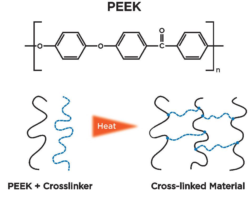
For engineers tasked with finding materials and solutions that can withstand hydrogen’s harshest environments, cross-linked polyetheretherketone (PEEK) materials have been a leap forward.
PEEK has long been a favourite in the energy sector. It originated in the early 1980s as a high-performance thermoplastic known for its exceptional durability and resistance to extreme conditions. But as oil wells became deeper and systems began to operate under increasingly severe conditions, standard PEEK reached its performance limits, especially in scenarios involving high pressure and high temperature (HPHT) environments.
The introduction of the first cross-linked PEEK, Arlon® 3000XT in 2013 by Greene Tweed, marked a key development in material science.
What exactly is cross-linking? It is a process of chemically bonding polymer chains together, forming a robust 3D network within the material. In the case of PEEK, it can be achieved through various methods, such as radiation (surface cross-linking mainly) or chemical cross-linking agents, resulting in molecular bonds that significantly enhance the polymer’s molecular properties, without compromising its inherent properties.
Materials such as Arlon 3000XT feature enhanced thermal and chemical stability, greater mechanical strength, and exceptional resistance to wear and degradation under extreme industrial requirements.
Cross-linked PEEK remains a specialty material, if one is not careful, inferior chemistry can unintentionally create weak points for chemical attack, and chemical robustness and quality must be maintained when developing such materials. In Arlon 3000XT, this can be done by combining chemical cross-linking while still maintaining crystallinity, for enhanced properties over and above a purely chemically modified or semicrystalline polymer with no cross-linking.
Current materials do not reliably service some of the required conditions created by the production, transportation, and handling of the lightest element, hydrogen. Success requires improvements in wear, chemical, mechanical, and thermal properties. These properties are vital for hydrogen applications, where materials must withstand high pressures, temperatures, and corrosion. Cross-linked PEEK material enables the development of more durable and efficient components, such as seals and gaskets, which are critical to the safe and effective storage and transport of hydrogen.
Through development of the Arlon 3000XT, Greene Tweed’s Advanced Technology Group (ATG) has seen first hand how it can enhance reliability and performance in hydrogen and several other energy applications. Driven by the demands of this industry, the latest compound in the series, Arlon 3160XT – a glass-filled cross-linked PEEK – was specifically developed to retain its performance at high temperatures.
Through close collaboration with its customers and partners, Greene Tweed has gained deep insights into the transformative impact of these materials. The hydrogen industry is recognising that these materials offer a range of advanced properties that make them highly suitable for demanding applications in high-performance environments, such as the following features.
These materials maintain their stiffness and strength at temperatures where lower-grade polymers would begin to melt or deform. Traditional PEEK can soften above 300°F (149°C), while cross-linked PEEK has been tested for stable strength, even when heated above 752°F (400°C) for over an hour. This opens up new possibilities for hydrogen applications in harsh process environments. This makes it an ideal choice for structural components like electrolyser frames or fuel cell compression end plates, which must withstand extreme forces without deforming.
Hydrogen systems often involve exposure to high concentrations of acidic gases, bases, and moisture. While standard polyketones and PEEK already demonstrate base-level chemical resistance, tests on the new cross-linked PEEK materials show minimal
We move big things to zero with hydrogen technologies enabling sustainable energy systems.
Producing enough green hydrogen is key to decarbonizing hard-to-electrify businesses. Our Power-to-X processes convert renewable electricity and water into green hydrogen and net-zero fuels. Through QuestOne, we mass-produce PEM electrolyzers and scale up green hydrogen production.
everllence.com

to no deterioration after extended exposure to these hydrocarbons and corrosive agents at extreme temperatures, making it a reliable choice for seals, gaskets, and structural components where failure is not an option. Compatibility in hydrogen and carbon dioxide environments (high pressure and temperature cycling) was also verified at several US national laboratories.
Creep, the deformation of a component over time under a load, is a critical issue for materials used in static sealing applications held under load for extended periods. Cross-linked PEEK displayed 40% lower creep rates under 500°F (260°C) shear loads compared to traditional PEEK and PEK. This means critical components like seals and backup rings can withstand sustained continuous high pressures, enhancing the reliability of components used in hydrogen systems.
When subjected to extrusion testing at 35 000 psi, at 550°F (288°C), the new PEEK materials performed over 200% better than carbon-filled PEEK. Its ability to hold shape and maintain sealing under extreme load conditions makes it an exceptional material for hydrogen system sealing.
These PEEK materials enhance reliability in hydrogen-rich ecosystems by significantly reducing molecular diffusion. Hydrogen molecules are incredibly small and can weaken many materials over time. Laboratory testing at national laboratories has verified that Arlon 3000XT has a very low diffusion rate and no measurable chemical interactions. This ensures long -lasting containment and material stability, further reinforcing its suitability for high-stress, high-performance applications. Together, these features establish cross-linked PEEK as a leading material for demanding systems and beyond.
Cross-linked PEEK materials are revolutionising equipment reliability in hydrogen-rich applications. Greene Tweed has extensive experience which demonstrates the value of this technology across various applications.
For example, a Fortune 500 engineering company recently developed a new pressure relief valve designed for critical gas applications. Given its tendency to leak and cause material degradation, standard materials would not suffice for these valves that are designed to protect tanks and vessels used in high-pressure gas applications. The company selected Arlon 3000XT seating which was able to deliver leak-tight performance, resistance to embrittlement, optimum seat tightness, high reliability, and long service life, even at pressures up to 20 000 psig (1380 bar).
Pressure relief valves are not the only component able to utilise the benefits of this material. These materials deliver critical benefits across multiple applications:
y Electrolyser frames and plates: electrolysers, critical for green hydrogen production, operate in demanding environments with caustic electrolytes and high temperatures to split water. Standard materials often struggle under these conditions, deforming or losing integrity. Cross-linked PEEK can maintain structural strength, ensuring bolted components remain secure, minimising leaks and retaining torque.
y Valve seats: when used in hydrogen systems, valve seats face unique challenges – such as resisting high mechanical forces while sealing against the element’s small molecular size. Cross-linked PEEK materials are designed to combat creep and deformation, maintaining effective sealing even after extended exposure to high pressure.
y Fuel cell compression end plates: fuel cells require materials that combine high compressive strength with excellent electrical insulation. Cross-linked PEEK serves well in this role, offering durability and long-term reliability.
y Compressor wear components: hydrogen compression presents significant challenges due to lubricant-free conditions and high pressures, which can quickly wear out components such as piston rings or wear rings. Leveraging these PEEK materials can improve the durability and efficiency of reciprocating compressors, enabling them to endure higher pressures while minimising wear.
As the hydrogen infrastructure expands, unexpected challenges are arising that show traditional materials cannot meet the demands of modern energy systems. Advanced materials have been developed to fill the gap. They offer the perfect balance between performance and reliability, paving the way for safe, reliable, and efficient hydrogen equipment tasked with building the future of energy.


Visit our website today: www.globalhydrogenreview.com
Reza Agahi and Behrooz Ershaghi, Nikkiso Clean Energy & Industrial Gases, USA, consider the design of turboexpanders in primary and deep cryogenic refrigeration cycles.


existing processes or finding a new one to produce hydrogen.
Transportation of hydrogen is also discussed extensively in literature and at conferences.
Transportation options are either in a liquid state or under super high-pressure conditions. Utilising hydrogen carriers such as ammonia or methanol has also been proposed. Research projects and pilot plants are in the works to develop hydrogen carrier options.
Transportation of liquid hydrogen (LH 2 ) is the most practical means at the present time. This transportation mode is currently supplying hydrogen to refuelling stations and consumers who need fuel warehouse equipment inside the enclosed spaces. The major disadvantage of LH 2 transportation is loss of hydrogen due to high boil-off rates.
Hydrogen liquefaction is an established process in principle. The difference(s) amongst the patented processes is in optimisation of the number of rotating equipment and conversion of hydrogen isotopes, ortho and para.
There are two refrigeration cycles in any hydrogen liquefaction plant. The primary refrigeration cycle utilises nitrogen as the cooling medium. The deep cryogenic cooling cycle utilises either helium or hydrogen for the cooling and liquefaction of the hydrogen throughput.
This article presents the design and manufacturing of turboexpanders utilised in either primary or deep cryogenic refrigeration cycles. The turboexpanders are designed with active magnetic bearings (AMBs) and are therefore totally oil-free turbomachines.
Application of radial inflow turbine, turboexpander, in industrial refrigeration dates to the late 1930s when Dr Linde utilised it in the air separation process. 1 Dr Swearingen introduced turboexpander in hydrocarbon applications in the early 1960s. 2
Turboexpanders expand the high-pressure fluid to a lower pressure and extract energy. The latter energy is available at the other end of the expander rotor to be recovered by a centrifugal compressor or by an electric generator.
Turboexpander technology has evolved since its first application in the natural gas processing and gas liquefaction industries. The improvements are not only due to the analytical tools and associated software but also due to the advancements in dry gas seals, integral gearbox and AMBs. 3,4
Any closed loop refrigeration cycles should have zero contamination. Turboexpanders with magnetic bearing or gas bearings are the ideal options. Gas bearing turboexpanders are for small liquefiers only. AMBs, on the other hand,
JET ® Gen 3™ Delivers Less NOx With Lower Cost.
Extraordinary happened when Zeeco and ExxonMobil combined forces to develop a new burner that put industry on the path to net zero. The ZEECO® FREE JET Gen 3 uses proven technology plus an innovative square burner design and staged fuel to deliver remarkable performance improvements—even with tight burner spacing —across a range of fuels. Achieve single digit NOx emissions from 100% natural gas to 100% H2 firing.
Learn more about the advances made with the ZEECO FREE JET Gen 3:
Table 1. Overall isentropic efficiency of hydrogen expanders
have no permanent magnets and hence are fully compatible in a hydrogen environment and in any size liquefaction plants.
Figure 1 depicts the cross-section of a turboexpander-compressor with AMB. The high-pressure fluid enters the expander, passes through the inlet guide vanes, and exits in an axial direction from the expander wheel. In general, half of the available energy is used to accelerate fluid flow through the inlet guide vanes and the other portion expands through the wheel where the energy is extracted and refrigeration is produced.
In an expander-compressor (EC) configuration, the shaft is short and the expander wheel is at one end and at the other end of it is a compressor wheel. The compressor wheel acts as the load for an expander and uses the available power to compress the incoming fluid to a higher pressure. The expander-compressor could be designed with an AMB and in most cases, it could be designed as a hermetically sealed turbomachine.
There are processes where the expander refrigeration is required but there is no fluid to be compressed. Expander-electric generator is a preferred configuration in those circumstances. For the expander-electric generator there are two options, expander-integral gear -generator and expander-high-speed generator. The latter is an option that could utilise AMB.
Figure 2 shows an expander-integral gear and Figure 3 depicts an expander-high-speed-generator with AMB.
The nitrogen refrigeration cycle of a hydrogen liquefaction plant normally consists of two expander-compressor units in the pre-boost configuration. The so-called warm-end and cold-end combination refrigerates nitrogen down to -150°C, which is sufficient for precooling of the process hydrogen.
Nitrogen expander-compressors with AMB have been in operation since the mid-1990s and the design details and integration into the nitrogen process are well established. Warm nitrogen is used as seal gas and cooling gas. The bearing housing is normally vented to the suction of the recycling nitrogen compressor. All seal gas and cooling gas is recovered. The only impact is on the volume of nitrogen in the cooling loop which is increased by 3 - 5%.
An expander-compressor with AMB had not been operated in pure hydrogen and industrial application until a few years ago. There are numerous challenges in the design and integration of hydrogen expander-compressors in the hydrogen cooling loop system.
The first challenge is the number of EC units and their arrangements in parallel or in series. In general, the larger the capacity of a hydrogen liquefaction plant, the more EC units.
The next challenge is to have a hydrogen stream with suitable pressure for the low-pressure compressor stage. Hydrogen compressors are simply acting as a load for its expander. These compressors are normally with a large flow because the high compression ratio is not practical for low molecular weight fluid like hydrogen.
The third challenge is associated with the gas dynamics performance of the EC, the design of its variable inlet guide vanes and the expander wheels due to the high enthalpy across the expander stage.
The fourth challenge is to control and monitor expander seal gas to prevent deep cryogenic expander process gas leaks to the bearing housing and at the same time minimise the expander process gas dilution with the warm seal gas to deteriorate the expander isentropic efficiency.
There are several more challenges associated with the mechanical design and rotor dynamics that are not discussed in this article.
Table 1 shows a typical gas dynamics performance of hydrogen turboexpanders for a hydrogen liquefaction plant. The isentropic efficiencies shown are ‘overall’ efficiencies. The overall efficiency of a multi-stage turboexpander system increases with the number of expansion stages and with the size of a liquefaction plant. For larger capacity hydrogen liquefaction plants, a turboexpander-generator configuration is more practical than loading the turboexpander with a compressor.
Green hydrogen is a must for pollution-free energy production of the future. Hydrogen production does not necessarily need to be located at or near its consumption. Hydrogen transportation from production location to the place of usage is a major challenge, however LH 2 is a practical avenue for transportation at the present state of technology. Turboexpanders are the critical turbomachines for an industrial scale hydrogen liquefaction plant. Hydrogen turboexpander design is a challenging undertaking due to deep cryogenic temperature and light molecular weight of the fluid. Therefore, turboexpanders with AMBs, hermetically sealed, and in a totally oil-free environment are the industry response to hydrogen transportation needs.
1. AVETIAN, T. and RODRIGUEZ, L.E., ‘Fundamentals of Turboexpander Design and Operation’, Hydrocarbon Processing , (2020).
2. SWEARINGEN, J.S., ‘Turboexpanders and Processes That Use Them,’ Chemical Engineering Progress , Vol.68, No. 7, (1972).
3. AGAHI, R. R., ‘Turboexpander Technology Evolution and Application in Natural Gas Processing’, Gas Processing Association Convention, (San Antonio, Texas, US), (2003).
4. AGAHI, R. and ERSHAGHI, B., ‘Hydrogen Liquefaction Process Requirements for Cryogenic Turboexpanders’, Asia Turbomachinery and Pump Symposium, (Kuala Lumpur, Malaysia), (2024).
From planning to construction, we guide our clients through a new era of energy, making their dreams a reality.
80 years of hydrogen firsts. Experience to accelerate your vision.
Bolder V ision for the hydrogen economy


This special supplement focuses on decarbonisation pathways for the downstream sector, highlighting innovative technology and solutions that will help you thrive within the energy transition.

Scan the QR code to download your free copy of EnviroTech 2024.
Daniel Patrick, Atlas Copco Gas and Process, USA, considers how centrifugal compressor technology is being scaled to support liquid hydrogen carriers and help manage boil-off gas during transport.
As global decarbonisation efforts accelerate, hydrogen is emerging as a key energy carrier. It offers high energy density by mass, zero-carbon combustion, and the flexibility to serve as both a fuel and a feedstock. But its low volumetric energy density presents challenges, especially in long-distance transport.
Liquid hydrogen (LH2) shipping is one of the most viable approaches for enabling global hydrogen trade. However, successful LH2 transport hinges not only on cryogenic storage but also on reliable and safe boil-off gas (BOG) handling. BOG forms as LH2 naturally evaporates due to heat ingress, and without proper control, pressure buildup can jeopardise the safety and efficiency of the voyage.

Many of the regions investing heavily in hydrogen production – such as Australia, the Middle East, and parts of North Africa – are geographically distant from major consumption centres, like Japan, South Korea, and Europe. This mismatch between production and demand makes intercontinental shipping essential to achieving hydrogen’s full decarbonisation potential. Early projects are already targeting these long-distance trade corridors, with LH2 carriers expected to play a foundational role in linking global energy markets. This article explores how centrifugal compressor technology, already deployed aboard the Suiso Frontier pilot vessel, is now being scaled up to support large scale LH2 carriers. This technology will
play a central role in managing BOG during marine transport of LH2, enabling the next generation of hydrogen shipping.
As hydrogen production scales up, so must transport infrastructure. While pipelines and trucking will serve localised needs, intercontinental shipping is essential to link exporting countries with importing countries. LH2 offers a practical and increasingly sustainable option for this long-distance transport due to its increased volumetric energy density and inherent exergy.
A 2024 study by the European Commission’s Joint Research Centre found that LH2 shipped over 2500 km has a lower environmental impact than chemical carriers over the same distance, largely due to the carriers’ high energy demands of hydrogen cracking.1 Chemical carriers like ammonia, liquid organic hydrogen carriers (LOHCs), and methanol require significant energy input to pack and unpack hydrogen, while LH2 maintains hydrogen in its pure form and avoids additional energy input at the import location (where energy is often
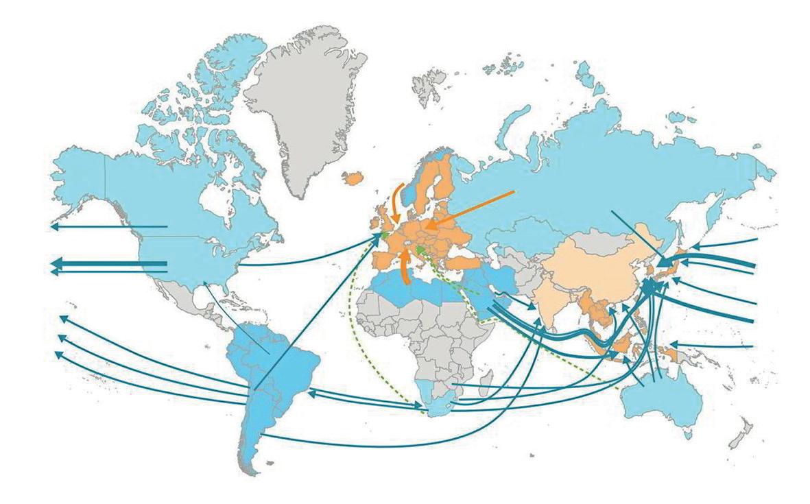
Figure 1. Expected global trade routes of hydrogen and derivatives by 2050. Image courtesy of Hydrogen Council/McKinsey.
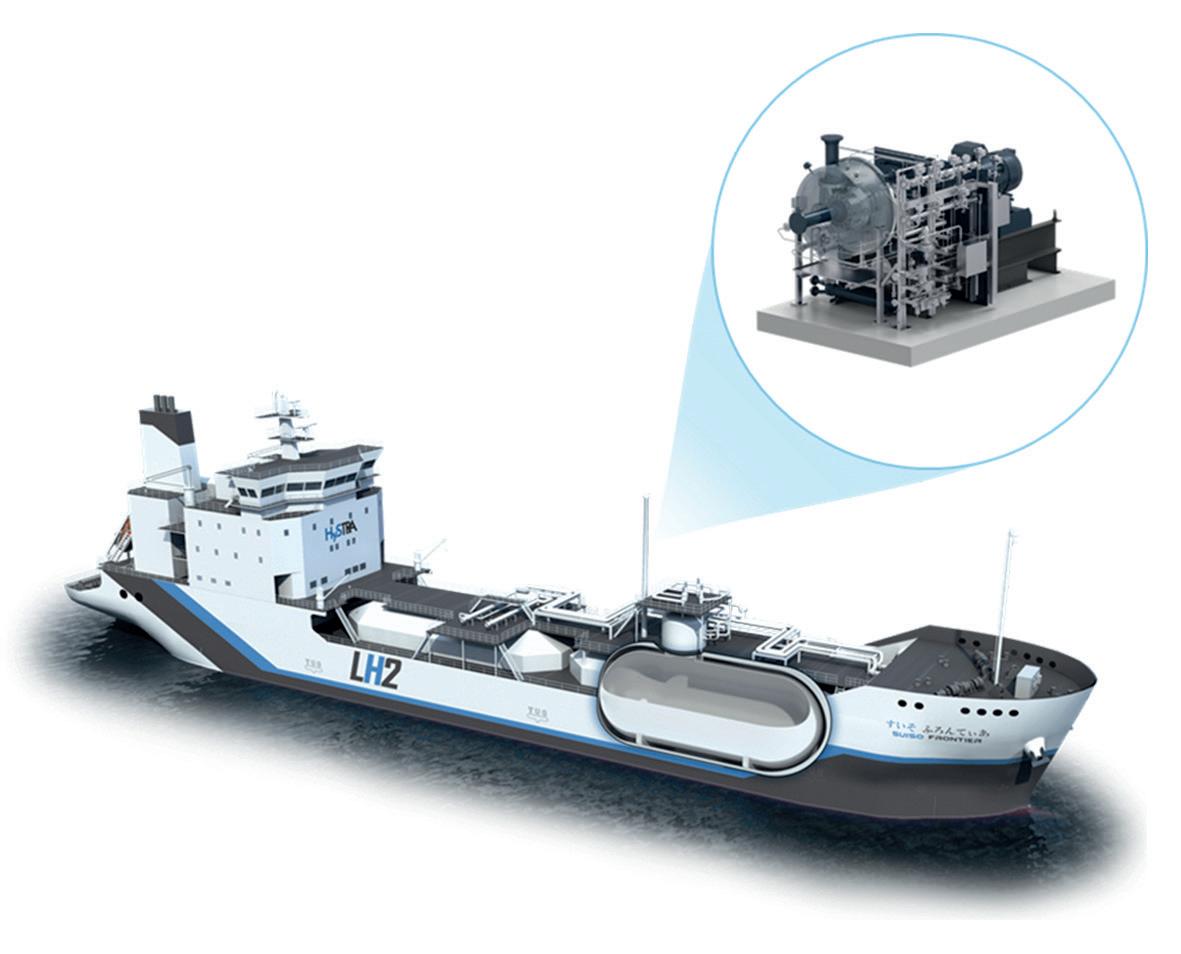
Figure 2. The Suiso Frontier, the world’s first LH₂ carrier, completed a successful round-trip voyage between Australia and Japan in 2022 using a BOG compressor from Atlas Copco Gas and Process. Ship image courtesy of HESC, altered by the author to include the BOG compressor.3
more expensive and carbon-intensive). In fact, the exergy in LH2, which is the usable stored energy from liquefaction, can be used at the import location for ‘free’ refrigeration or even power generation.
Despite these advantages, LH2 has historically seen limited use due to a lack of infrastructure and operational experience at the extreme cryogenic temperatures. That is now beginning to change, starting with pilot scale projects, like the Suiso Frontier
The Suiso Frontier, developed by Kawasaki Heavy Industries, was the world’s first purpose-built LH2 carrier. In 2022, the 8000 t vessel completed a demonstration voyage, transporting liquid hydrogen 9000 km from Australia to Japan.2
A key objective of this pilot project was to validate onboard systems required to safely store and handle LH2 at -253°C.
Among these systems, the high-duty (HD) BOG compressor, developed by Atlas Copco Gas and Process, played a central role. This centrifugal compressor was used during cargo loading and unloading to recover any LH2 vapour and return it to shore for storage or reliquefaction. Although the Suiso Frontier did not use BOG as a fuel, the successful validation of the onboard HD compressor laid the foundation for more integrated BOG strategies on future vessels.
BOG compressors are essential for maintaining safe cargo tank pressure on LH2 carriers. As heat leaks into the cryogenic storage tanks, a small portion of the LH2 vaporises, generating BOG. Compression is necessary to raise this vapour to a usable pressure for either storage, onshore reliquefaction, or onboard consumption as fuel.
Without active BOG compression, pressure would gradually build in the tanks, eventually triggering overpressure relief valves and venting valuable hydrogen to the atmosphere. BOG compressors prevent this loss by safely recovering and routing the vapour within the ship’s systems.
In LH2 shipping, the BOG handling approach mirrors that of LNG carriers, where:
y HD compressors are used during cargo loading and unloading.
y Low-duty (LD) compressors operate during steady-state transit to supply BOG as fuel for propulsion or auxiliary power.
While LNG carriers often incorporate onboard reliquefaction units, this is expected to be less common in LH2 shipping due to hydrogen’s significantly lower boiling point and the technical challenges of liquefying at -253°C. Instead, LH2 vessels are expected to consume BOG as fuel during transit, avoiding the need for onboard liquefaction while improving voyage efficiency and minimising cargo losses.
Although the Suiso Frontier pilot vessel did not use BOG for fuel, future LH2 carriers are expected to adopt this dual-compressor strategy. As the scale and complexity of hydrogen shipping increases, compressor system reliability, thermal management, and safety become even more critical. Shipbuilders and compressor OEMs that can draw on decades of LNG experience will be well-positioned to meet these emerging demands.


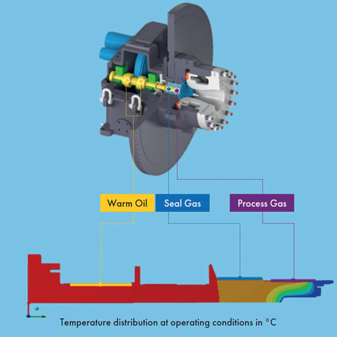
Figure 3. Detailed analysis of the shaft temperature was performed on the Suiso Frontier BOG compressor rotor to ensure proper design for the LH₂ conditions.
The Suiso Frontier project provided valuable insights into the real-world behaviour of LH2 systems. One of the most significant technical challenges was managing the thermal environment around the BOG compressor, particularly in the shaft seal and housing area. At -253°C, the extreme cold of LH2 BOG creates a risk of atmospheric air condensing or even liquefying on exposed surfaces, presenting multiple hazards. Liquid oxygen can form if oxygen from the air condenses on cold metal, increasing fire and explosion risk. To mitigate this, the compressor housing must be carefully designed with robust thermal insulation to prevent the outer surface from reaching cryogenic temperatures. Common insulation strategies for LH2 compressors include vacuum-jacketed housings, though non-vacuum designs are gaining interest due to their relative simplicity.
Beyond insulation, a carefully engineered seal gas system is important to maintain a positive pressure of warm hydrogen around the shaft seals, preventing the cryogenic process gas from migrating towards the warm gearbox. The compressor designers used advanced CFD and thermal FEA to model heat transfer paths and ensure safe compressor operation under all operating and emergency scenarios.
These insights are now guiding the development of compressors for commercial scale carriers. The goal is to maintain safety, performance, and mechanical integrity while minimising thermal losses and sealing gas demand.
The successful demonstration of the Suiso Frontier confirmed the viability of LH2 marine transport at small scale. The next step is commercialisation. Designs are underway for carriers capable of transporting over 40 000 t of LH2, with tank capacities projected to reach 160 000 m3 within the
next decade. Commercial deployment of these LH₂ vessels is expected to begin as early as 2030.
Scaling up the BOG compressors involves engineering refinement, but not comprehensive redesign. The core HD compressor architecture – impeller design, shaft and seal systems, volute geometry – remains consistent with the design from the Suiso Frontier pilot. Larger machines will incorporate increased flow capacity through larger impellers, often operating at slightly slower rotational speeds (typically resulting in improved rotordynamics). Design solutions proven on the Suiso Frontier can be directly applied to the next generation of HD BOG compressors. In fact, some design features actually get easier with scale. Consider thermal management, where the insulation becomes more effective at scale because the housing surface area increases more slowly than process flow rate.
Engineers are now focused on adapting these compressors for higher throughput while ensuring longterm reliability, maximum performance, and safe integration into the complex shipboard systems. These systems must perform under a wide range of operating conditions, from steady-state pressure control to transient events such as cooldown and warmup. Surprisingly, the ambient temperature operating conditions are some of the most challenging for a centrifugal BOG compressor due to the drastic change in density from cryogenic hydrogen to warm hydrogen. This causes a significant reduction in the available pressure ratio due to the much lower density of warm hydrogen compared to its cryogenic state. Nonetheless, designers are finding elegant ways to deal with this reality through multiple compressor configurations and operating procedures.
The Suiso Frontier project demonstrated that LH2 can be safely transported by sea and that BOG management systems can perform reliably under real-world marine conditions. This was a critical first step in validating the technologies needed for a global LH2 shipping network.
As the industry shifts its focus to scaling up, the next generation of LH2 carriers will require larger, more robust BOG handling systems to manage higher flow rates, support cargo transfer, and ultimately enable hydrogen-fuelled propulsion. Lessons learned from the pilot vessel are enabling OEMs like Atlas Copco to optimise BOG compressor designs with improved thermal management strategies and more streamlined system integration for future commercial fleets.
With full scale deployment targeted by 2030, LH2 BOG compressors will remain a critical enabler of safe, reliable, and efficient global hydrogen trade.
1. ARRIGONI, A., Dolci, F., et al., ‘Environmental life cycle assessment (LCA) comparison of hydrogen delivery options within Europe’, Joint Research Centre, European Commission (2024).
2. Toward a New Era of Hydrogen Energy: Suiso Frontier Built by Japan’s Kawasaki Heavy Industries’, Hydrogen Council, https:// hydrogencouncil.com/en/toward-a-new-era-of-hydrogen-energysuiso-frontier-built-by-japans-kawasaki-heavy-industries/
3. ‘About the Pilot’. Hydrogen Energy Supply Chain, https://www. hydrogenenergysupplychain.com/about-the-pilot/

Aaron Lapsley, Hyroad Energy, considers how to solve the problem of losses that occur during liquid hydrogen storage and refuelling operations.
Hydrogen has long been touted as a key pillar of the clean energy transition, and recently it has been gaining traction as an alternative fuel for transportation primarily due to its zero-emission potential powering fuel-cell electric vehicles (FCEVs). FCEVs emit only water vapour at the tailpipe (and some heat), making them a clean energy alternative to traditional gasoline-power vehicles when the hydrogen is produced, stored, and dispensed with low carbon intensity.
One of the constant and endless debates in the hydrogen industry, fuelled by evolving technological progress, is whether high pressure gaseous or cryogenic liquid hydrogen (LH 2) systems are the better option. This remains
unclear, and there are strong arguments for and against both. And this debate will likely continue for some time as the industry matures.
But within this backdrop, one part of the debate has become increasingly clear: for LH 2 to truly scale and serve as a decarbonisation solution, the industry must solve the challenging problem of losses that occur during LH 2 storage and refuelling operations.
At LH 2 refuelling stations today, overall loss rates in excess of 20% are still common, making it a fundamental barrier to profitability and, ultimately, slowing mass adoption for transportation.
This happens because LH 2 is extremely cold. At the pressures typical of a liquid hydrogen storage tank, it evaporates at around -245˚C. As it warms – even by a few degrees – gas evaporates out of the liquid, tank pressure builds, and operators vent hydrogen into the atmosphere. There are three main reasons this matters.
First, it dramatically increases the total cost of ownership (TCO) for hydrogen-powered fleets. Hydrogen is currently expensive; its wholesale price is the most sensitive variable in hydrogen-powered commercial vehicle unit economics (inclusive of the CAPEX and OPEX of refuelling infrastructure and trucks). Every kilogram lost raises prices for fleets.
Second, it weakens hydrogen’s environmental case. With a global warming potential (GWP) value of between 10 - 12 (estimates vary), vented hydrogen gas is not nearly as harmful as most refrigerants or even unburned methane, but it is not climate neutral. To hit the low carbon intensity of dispensed fuel that many sustainability-driven shippers and BCOs desire, vented hydrogen losses must be accounted for and minimised.
Third, high loss rates make it harder to operate refuelling stations, which ultimately slows adoption by negatively impacting customers. Refuelling operations must have high availability and reliability for drivers and logistics managers. Unfortunately, losses at operating LH 2 stations have proven volatile and dependent on a host of complex factors. This has made it more difficult to plan for steady, consistent bulk storage tank refill orders from LH 2 suppliers, which can, in turn, lead to increased station downtime and more numerous, costly partial-fill orders. These can also lead to station downtime during the refill process, as many stations were not designed to dispense fuel to vehicles will refilling their single bulk storage tank.
LH 2 loss at end-use refuelling stations comes from three major stages of the hydrogen value chain, from refilling to dispensing into vehicles. These have all played out in real-world refuelling stations, where operators and engineers have had to learn through trial and error what works and what fails.
When a bulk delivery truck refills a station’s main tank, gaseous hydrogen already sitting at the top of the tank
is displaced and vented. The lower the LH 2 level prior to refilling, the more gas is likely to be lost. In a design simulation for a typical 18 000 gal. tank (4000 kg nominal LH 2 storage capacity), modelled losses during refill cycles regularly exceeded 350 kg per delivery. This is the result of many factors, including warm(er) LH 2 at or near its boiling point, static tanks that do not promote mixing, the amount of LH 2 remaining at the time of refill, and single-hose refilling systems that do not manage pressure efficiently during offloading.
By contrast, in simulations where tanks were kept consistently colder and at lower pressure using supplemental refrigeration, refill loss dropped to under 80 kg on average, a > 75% reduction. This shift was attributed to colder tank temperatures, improved inlet pressure and flow rate control, and dual-hose delivery systems that allowed displaced gas to be re-routed instead of vented under pressure.
Normal evaporation rate (NER) is the slow, constant, and inevitable process of heat transfer into cryogenic storage tanks, raising temperature and pressure over time. Even with the best insulation available, some level of heat gain is simply unavoidable. This type of boil-off is slow and fairly steady, and because LH 2 is so cold compared to any range of normal ambient conditions, it is only marginally affected by weather variations. It just inexorably exists, and it becomes more obvious when LH 2 is allowed to sit idle for longer periods of time. The good news is that NER is small relative to refill losses and pump losses. Estimates are typically in the range of 1 - 2% of full storage mass per day.
Potentially the most surprising losses (at least for the uninitiated) come from the main refuelling pump train downstream of the bulk storage tank. Boil-off from cooling down the cold end of the pumps is one example. Hydrogen is compressed to a very high pressure in the tanks on an FCEV. For an LH 2 station, this requires pumps that must intake fluid at less than 30K at their inlet and pressurise it up to around 700 bar. The cold end of those pumps must, of course, be very cold – but if no vehicles arrive for several hours or overnight, the system naturally warms up. When the next driver pulls in to refuel, LH 2 is typically circulated through the warm(er) steel components, causing flash boil-off and often immediate loss from venting.
In modelled statistical simulations of 1000 pump cooldown cycles, average losses were 12 kg per event, with spikes as high as 40 kg depending on several variables, including ambient conditions, downtime, and the mass of metal to be cooled. Operator experience has shown that these losses can be mitigated by maintaining more consistent throughput of refuelling events, and there is some compelling evidence that maintaining pump cold ends at an optimised temperature even during extended periods between refuelling events can reduce overall boil-off as well. But overall, this remains a significant and under addressed opportunity for LH 2 technology improvement.
In addition to pump cooldown, many pumps currently in use experience significant boil-off during normal pumping operations, a consequence of components that were designed for cryogenic fluids but not necessarily optimised for LH 2. Newer designs hitting the market are expected to limit this type of loss and promise to improve the reliability of the pumps themselves.
Despite the challenges, LH 2 is still a promising transportation fuel option. All of the loss issues are manageable with some improvements in technology, engineering, and operations.
Liquefaction and cryogenic fluids are not new. LH2 has been used by the US space programme for over 60 years. But its use in commercial applications is still relatively nascent, and key components in LH2 refuelling infrastructure for vehicles were never really designed or optimised for LH2 applications.
Some equipment like pumps and compressors, for example, have had designs repurposed or upfitted from LNG systems because the application is a close analog and equipment is readily available. Unfortunately, hydrogen has enough differences that it has caused complications. It is lighter (less dense), colder when liquefied, and exists in two different isomeric states with different energy levels, affecting liquefaction and storage. The thermodynamics and mechanics of LH2 are not quite the same as other common liquefied industrial gasses, and thus application-specific systems and equipment are needed for optimal LH2 performance, particularly loss avoidance.
In many current LH2 station builds, developers implemented boil-off recapture systems. These systems are designed to collect and compress boiled-off hydrogen and store it for future use. These systems work but with added complexity and cost. These designs are effectively creating a small, sub-scale gaseous hydrogen plant alongside the LH2 systems, which arguably negates much of the simplicity of LH2 refuelling stations that directly compress to vehicles.
While there have been some clever applications of boil-off gas recapture, it is not clear that it is the most optimal solution, especially when compared with systems that prevent boil-off in the first place. In practice, the uncertain benefit to infrastructure TCO and operational headaches have left the industry looking for better answers.
Many of today’s existing stations were designed to prove that hydrogen could work in the first place – not to make it efficient at scale. That is starting to change.
The next generation of LH2 refuelling infrastructure is looking more promising, informed by what has not worked so well: systems that required constant human oversight, equipment not originally designed for liquid hydrogen, and operations that tolerated significant loss. Developers are now designing and building a new generation of refuelling stations that minimise idle time thermal cycling, integrate advanced monitoring for predictive maintenance, and use optimised LH2 equipment and technology.
With the addition of supplemental refrigeration to keep LH2 in storage at lower pressure and temperature, the bulk tank refilling process and downstream high-pressure pumps operate more predictably – and loss becomes the exception, not the rule. For this to work, loss minimisation must be an operational mindset built into the infrastructure from the start.
Some leaders in the hydrogen refuelling industry are starting to form a consensus point of view that perhaps the best way to reduce LH2 loss is to prevent the LH2 from boiling off in the first place.
One of the tools to do so is a supplemental refrigeration system. This system is integrated with the bulk storage tank to remove heat, alongside a cryogenic refrigerator that works around the clock to remove heat, keeping the hydrogen at a stable temperature and pressure. Because the bulk storage tank stays colder, less LH2 boils off to gas, and any that does can potentially be recondensed in the tank instead of vented.
The other major area of innovation is the next generation of pumping systems designed and optimised for LH2 direct compression vehicle refuelling. The latest pump packages are showing dramatic reductions in cylinder blow-by and cold-end boil-off, as well as better refuelling flow rates, higher resilience, and lower maintenance costs.
Collectively, these advancements have the capability to dramatically reduce overall station loss during both idle periods and active dispensing.
In thousands of simulated operating scenarios, the impact was clear:
y Hydrogen loss during refills dropped by more than 75%.
y Most station scenarios could pay off the refrigeration system in under five years.
y Overall station loss rates dropped reliably below the 5% threshold needed to compete with diesel on cost and carbon.
y Station refuelling flow rates (and thus vehicle refuelling times) are improved.
These results of modelling offer a clear direction. The next step is building infrastructure that reflects what we now know can work at scale. This shift serves fleets, hydrogen industry players, regulators and the climate, all at once. It enables clearer TCO forecasting, opens the door to more aggressive incentives, and builds confidence among early adopters.
The path to zero-loss hydrogen refuelling is becoming clearer by the day, and so is the business case. Getting there will take the usual combination of focus, coordination, investment, and urgency – but the tools, experience, and knowledge to make it happen are increasingly available. If hydrogen is going to live up to its ultimate promise, then companies should not accept throwing it away.
Reference
1. SAND, M., SKEIE, R.B., SANDSTAD, M. et al. ‘A multi-model assessment of the Global Warming Potential of hydrogen’, Commun Earth Environ vol. 4, 203 (2023). https://doi. org/10.1038/s43247-023-00857-8

Greg Gosnell, GenH2, USA, discusses why zero-loss liquid hydrogen technology will be key to large scale mobility fuelling.
As hydrogen technologies evolve, liquid hydrogen (LH2) is emerging as a powerful force in energy transition. While hydrogen has long been recognised as a versatile, zero-emission energy carrier, confusion still lingers – especially around the comparative advantages of LH2 vs gaseous hydrogen (GH2). Yet, the verdict from industry experts, engineers, and infrastructure developers is becoming increasingly apparent: LH2 is the superior choice, particularly for mobility and large scale applications.
With hydrogen poised to play a central role in decarbonising sectors such as heavy-duty transport, bus mass transit, aviation, maritime, and backup power storage, scaling efficiently and safely is no longer optional, it is essential. To unlock hydrogen’s full potential and accelerate the transition to net zero emissions, two strategic priorities must be addressed:
y Broad recognition and adoption of LH2 – not GH2 – as the future of large scale mobility fuelling.
y Deployment of technologies that eliminate every mode of LH2 loss during transfer and storage.
While GH2 and LH2 each play essential roles in the developing hydrogen economy, LH2 delivers critical advantages for high-efficiency, high-density applications:
LH2 is approximately 800 times denser than its gaseous counterpart at atmospheric pressure and up to eight times denser than highly compressed GH2. This translates into a dramatically smaller storage and delivery footprint – critical for fuelling stations in dense urban environments, space-constrained industrial sites, and mobile refuelling platforms.
Unlike GH2, which must be compressed to pressures up to 700 bar (10 000 psi) for storage and transport, LH2 is stored at cryogenic temperatures (~-253°C) and very low pressure,
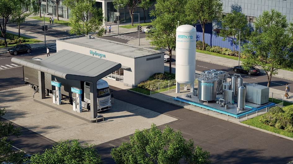
Figure 1. An example of a zero-loss LH2 system, including refrigerated controlled storage for a hydrogen refuelling station.
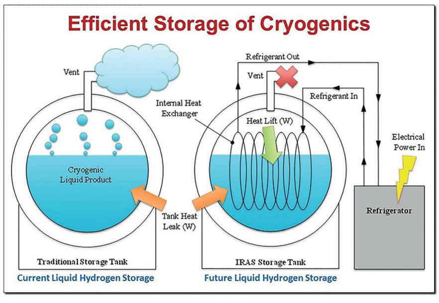
Figure 2. NASA GODU for LH2 study – diagram with simplified comparison of a traditional storage tank and an IRAS System.
reducing risks associated with high-pressure systems. This makes LH2 infrastructure inherently safer to operate and maintain.
One LH2 tanker can deliver the same amount of hydrogen as up to eight GH2 trailers, vastly improving transport economics. In addition, LH2 fuelling stations can dispense several tonnes per day through a single pump – something that would require multiple GH2 compressors and complex systems, increasing both capital and operational costs.
When hydrogen refuelling stations use GH2 as the storage medium, the only option is to fuel GH2 onboard tanks. However, when using LH2 as the storage medium, the operator and end-user can employ either GH2 or LH2 onboard tanks.
Despite its promise, hydrogen’s small molecular size and volatile properties present formidable engineering challenges, especially for LH2. Hydrogen loss during transfer, storage, and dispensing is a significant barrier, with real-world losses in some systems exceeding 40%. These losses are not just
economic – they represent wasted clean energy and a setback in emissions reduction goals.
During offloading from a tanker into a bulk storage tank, cryogenic LH2 meets a warm bulk storage tank and warmer, saturated LH2 remaining in the tank. When this occurs, the LH2 vaporises, causing pressure to build up in the receiving tank, which forces operators to vent the GH2 vapour. This process alone can result in a hydrogen loss of up to 30% per transfill.
Even highly insulated cryogenic tanks allow some heat to seep in, resulting in a daily loss of 1 - 3% through boil-off. Over time, this becomes a significant operational cost.
When warmer, saturated LH2 is pumped into the dispensing interface via the cryopump, cavitation (i.e., bubbles) occurs, which leads to hydrogen losses. Depending on the quality of the LH2 being delivered into the cryopump, losses of up to 10% (or more) can occur.
These losses can accumulate quickly. A single hydrogen station dispensing 2000 kg/day with only a 20% loss could result in over US$1 million in lost/vented hydrogen each year, not to mention increased emissions from vented gas.
The next frontier in hydrogen infrastructure is zero-loss LH2 technology – specifically solutions that prevent boil-off, venting, and other forms of leakage. These systems are not just helpful; they are essential for the economic and environmental viability of hydrogen mobility.
At the heart of this transformation are active, refrigerated storage systems that can maintain precise temperature and pressure conditions. These systems, often referred to as ‘controlled storage,’ utilise integrated refrigeration of the LH2, enabling zero-loss cooldowns, offloading, and daily operation. The key differentiator of controlled storage is its ability to preserve LH2 and prevent vaporisation into GH₂ by actively refrigerating the LH2. This is much more efficient than the energy-intensive alternative of capturing and reliquefying boil-off gas. Incorporating controlled storage into LH2 storage infrastructure yields clear advantages.
Benefits of zero-loss LH2 systems include:
y No venting means no emissions.
y Zero-loss transfilling and tank cooldown.
y Significantly reduced operating costs.
y Higher energy density and infinite storage durations without losses.
y Improved hydrogen refuelling station reliability and equipment longevity.
y High throughput refuelling with fewer assets.
y Flexibility to fuel both GH2 and LH2 onboard tanks.
y Complete control over the state of the hydrogen molecule.

Reaching a sustainable future is like kayaking. With a skilled partner, you can make the right decisions.
Reaching a sustainable future is demanding in many ways. Obstacles and change must be well anticipated to make the right decisions. We are ready to tackle these challenges with you! We will help you to improve your processes to meet your ESG goals, operational optimization and sustainable manufacturing efforts. Let’s team up to improve!
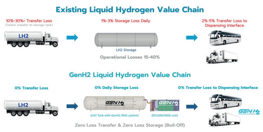
y Successfully operated across tank fill levels of 33%, 67%, and 100%, demonstrating uninterrupted thermodynamic control at any fill level.
y Maintained temperature, pressure, and mass flow stability over ~19 months of testing.
y Delivered zero boil-off performance as long as refrigeration matched heat ingress, providing clear proof of the controlled storage concept.
y Energy cost to prevent loss is a fraction of the cost to re-liquefy after the loss has occurred.
The Ground Operations Demonstration Unit for Liquid Hydrogen (GODU LH2) – an initiative led by NASA’s Advanced Exploration Systems Programme and conducted at the Kennedy Space Centre – is the gold standard for analysing and validating the feasibility and performance of controlled storage systems.
The GODU-LH2 study was a ground-breaking NASA project aimed at transforming how we transfer, store, and manage LH2 – a key fuel used for space exploration. Traditionally, transferring and storing LH2 has been costly and inefficient. During the space shuttle program, nearly 50% of the hydrogen was lost due to evaporation and transfer issues during operations. Conducted between 2012 and 2016, the GODU-LH2 study addressed the issue head-on by introducing advanced cryogenic technology to refrigerate, control, and store hydrogen more effectively, thereby eliminating waste in the process.
One of the most important breakthroughs from NASA’s GODU-LH2 study was the ability to control the state of LH2 –a notoriously tricky fuel that is light, energetic, and easily lost to evaporation. By utilising advanced cooling and insulation technology, the study demonstrated how hydrogen can be stored long-term without losses, even allowing engineers to ‘tune’ its temperature and density for different mission requirements. As researchers noted, they were able to ‘dial in’ any point on the hydrogen phase curve and hold it indefinitely – a remarkable achievement in cryogenic fluid control.
Controlled storage represents a significant advancement for the broader adoption of hydrogen, not just for space exploration, but also for commercial applications such as fuel-cell vehicles, clean energy infrastructure, and backup power. The ability to store hydrogen reliably, efficiently, and with zero loss is precisely what is needed to make it a practical and sustainable part of our energy future.
GODU-LH2 demonstration goals
y Zero-loss storage and transfer (ZBO).
y Gaseous hydrogen liquefaction in situ.
y LH2 densification – increasing energy density by cooling below standard boiling point.
The results of the study were very clear: controlled storage is not a nice-to-have, it is mission-critical. Without refrigeration, hydrogen bulk storage tanks experience significant losses during fill and transfer operations. With controlled storage, these tanks can preserve fuel for anywhere from days to indefinitely – even under fuel demand cycling.
Controlled storage is not just a technological achievement; it is the foundation of a scalable, sustainable, and commercially viable hydrogen future built on proven science and measurable results, and it is not just theoretical. Industry leaders are deploying zero-loss LH2 systems in the field today.
In April 2025, a landmark partnership between Hyroad Energy, Bosch Rexroth, and GenH2 announced plans for the first zero-loss LH2 refuelling station in the US. Station construction is scheduled to begin later this year with operations expected to commence by 2026. Located in Texas, US, this station will demonstrate the technical feasibility and commercial viability of controlled storage while dispensing thousands of kilograms of hydrogen per day.
This achievement signals a pivotal moment for hydrogen mobility. As infrastructure scales from pilot programs to regional networks, the ability to store and distribute LH2 efficiently, safely, and without loss will determine the success of hydrogen as a mainstream energy alternative.
The GODU study did not just push technology; it changed the paradigm. We now know that an active heat removal process powered by external refrigeration has been proven to prevent boil-off and deliver hydrogen efficiently. Refuelling stations built on this model – such as the upcoming Texas installation – will usher in a new era of commercially viable, environmentally responsible hydrogen fuelling infrastructure, supporting carbon-neutral freight corridors, municipal fleets, aviation ground support, and backup power systems.
Zero-loss LH2 technology is more than an innovation – it represents a technological and commercial shift in how hydrogen can be stored, distributed, and consumed. It eliminates long-standing inefficiencies, reduces infrastructure costs, and enables a more sustainable and scalable energy economy.
If hydrogen is to fulfil its promise as the fuel of the future, LH2 and zero-Loss technologies will be the pillars that support its rise. The path to a clean, net zero world runs through cryogenic precision, innovative engineering, and bold investments in the future of LH2
Dr Rajendran Parthipan, Dr Barry Prince, and Dr Neil Glasson, Fabrum, New Zealand, highlight the design, functionality, and applications of small scale hydrogen liquefaction in an industry focused on large scale solutions.
Hydrogen liquefaction technology is crucial for the emerging hydrogen economy, offering a high energy-density-fuel alternative, in particular for the hard-to-abate sectors, including aerospace, heavy transport, and mining.
A key challenge in getting to large scale production is that the technology used for large scale production is not suitable for small scale production. Thus, alternative technologies are needed to provide the first small scale supplies of liquid hydrogen (LH2) that will enable the demand-side technology development needed to build the offtake demand, which in turn, is needed for the business-side of large scale production.

This article describes the current small scale hydrogen liquefiers in the market, highlighting their design, functionality, and applications and includes a significant case study, which demonstrates the deployment of LH2 at an active mining site in Western Australia.
Production of LH2 and its characteristics
LH2 is produced by cooling hydrogen gas to cryogenic temperatures (below -253˚C or 20 K at atmospheric pressure). This process involves several stages of cooling and compression, using technologies such as turboexpanders and cryocoolers. The preferred technology for hydrogen
liquefaction depends on the scale and consistency of the required production.
Hydrogen exists in two molecular forms: ortho-hydrogen and parahydrogen. At room temperature, hydrogen is predominantly in the ortho form (75% ortho, 25% para). However, at cryogenic temperatures, the equilibrium shifts towards the para form. The conversion from ortho to para hydrogen releases heat, which can cause some evaporation of the LH2. Catalysts are used to accelerate this conversion and minimise losses during storage. Achieving a high para ratio is advantageous for long-term storage, as it reduces boil-off losses and improves storage efficiency.
LH2 offers a high energy density compared to other methods of storing hydrogen, making it a practical alternative to fossil fuels for applications such as heavy transport, mining, and aviation. Unlike compressed hydrogen, LH2 provides a better energy package and can be stored in lightweight tanks without the need for high-pressure containment. This makes LH2 the only fuel that can match or even outperform hydrocarbon fuels in terms of specific energy – that is, energy per kilogram (kg) of the fuel system.
Figure 1 illustrates the comparative storage efficiency of various energy sources. Fossil fuels demonstrate superior
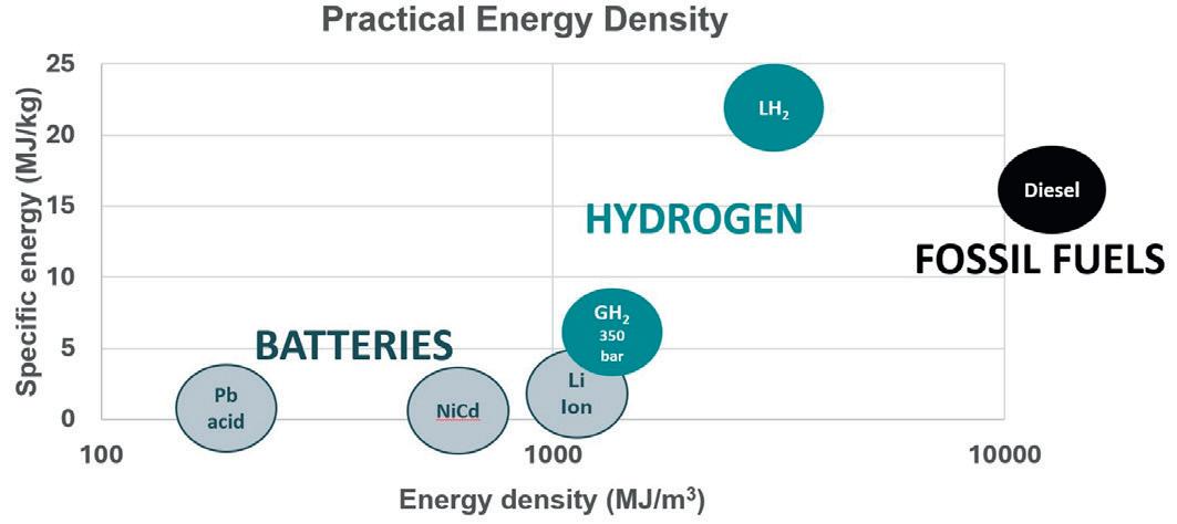
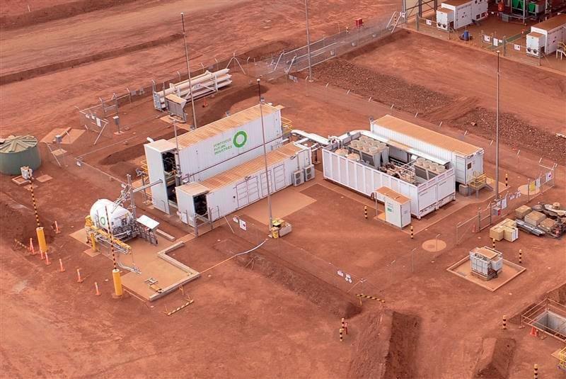
performance in both specific energy (energy per kg) and volumetric energy (energy per litre), making them highly efficient for energy storage and transport. While batteries are suitable for certain applications, they fall short on these metrics and cannot compete with fossil fuels in terms of specific energy and energy density. Hydrogen, however, stands out with more than three times the energy per kg compared to any carbon-based fuel. When stored as high-pressure gas, hydrogen surpasses batteries but still lags fossil fuels due to the size and weight of the storage vessels. But in liquid form, hydrogen can be stored in smaller lighter-weight tanks and can outperform fossil fuels on a per-kg energy basis, making it an extremely attractive option for high-performance energy applications. While large scale production of LH2 is the most cost-effective, the technologies used at scale such as Claude cycle or other turboexpander-based systems are not suitable for small scale applications. Early off-take demand for LH2 is variable and insufficient to justify the deployment of large-scale infrastructure. Until further demand-side technology development proves the commercial viability of LH2-powered products to build the demand for LH2, large scale production remains economically unfeasible. As a result, alternative production technologies must be employed to meet initial LH2 supply needs, enabling early market development and paving the way for future scale-up.
Small scale hydrogen liquefiers most commonly use pulse-tube, Stirling-cycle, and Gifford-McMahon (GM) cryocooler technologies. Each offers unique advantages depending on the operational context, but all share a key benefit: they can be readily ramped in production and routinely turned on or off to meet a variable demand profile making them ideal for early-stage and distributed hydrogen infrastructure.
Pulse-tube cryocoolers stand out for their low maintenance and high reliability. With no moving parts in the cold head (the region of the cryocooler where hydrogen gas is cooled), they eliminate mechanical wear, reduce vibration, and extend service intervals. This makes them especially well-suited for remote or rugged environments, where uptime and durability are critical.
Stirling-cycle cryocoolers are known for their high efficiency and compact design. They use a closed-cycle piston mechanism that allows for precise temperature control and rapid cooldown. While they do have moving parts at the cold head, which reduces the maintenance interval of the system compared to pulse-tube cryocoolers, modern designs have improved durability and noise reduction. Stirling systems are often favoured in applications where space and energy efficiency are priorities.
Gifford-McMahon cryocoolers offer robust cooling power and are widely used in industrial and laboratory settings. They operate using a reciprocating displacer and valve system, which provides strong cooling capacity at cryogenic temperatures. Though they require more maintenance than pulse-tube systems due to moving components, they are valued for their proven performance.
Together, these technologies enable flexible, responsive hydrogen-liquefaction systems that can adapt to fluctuating
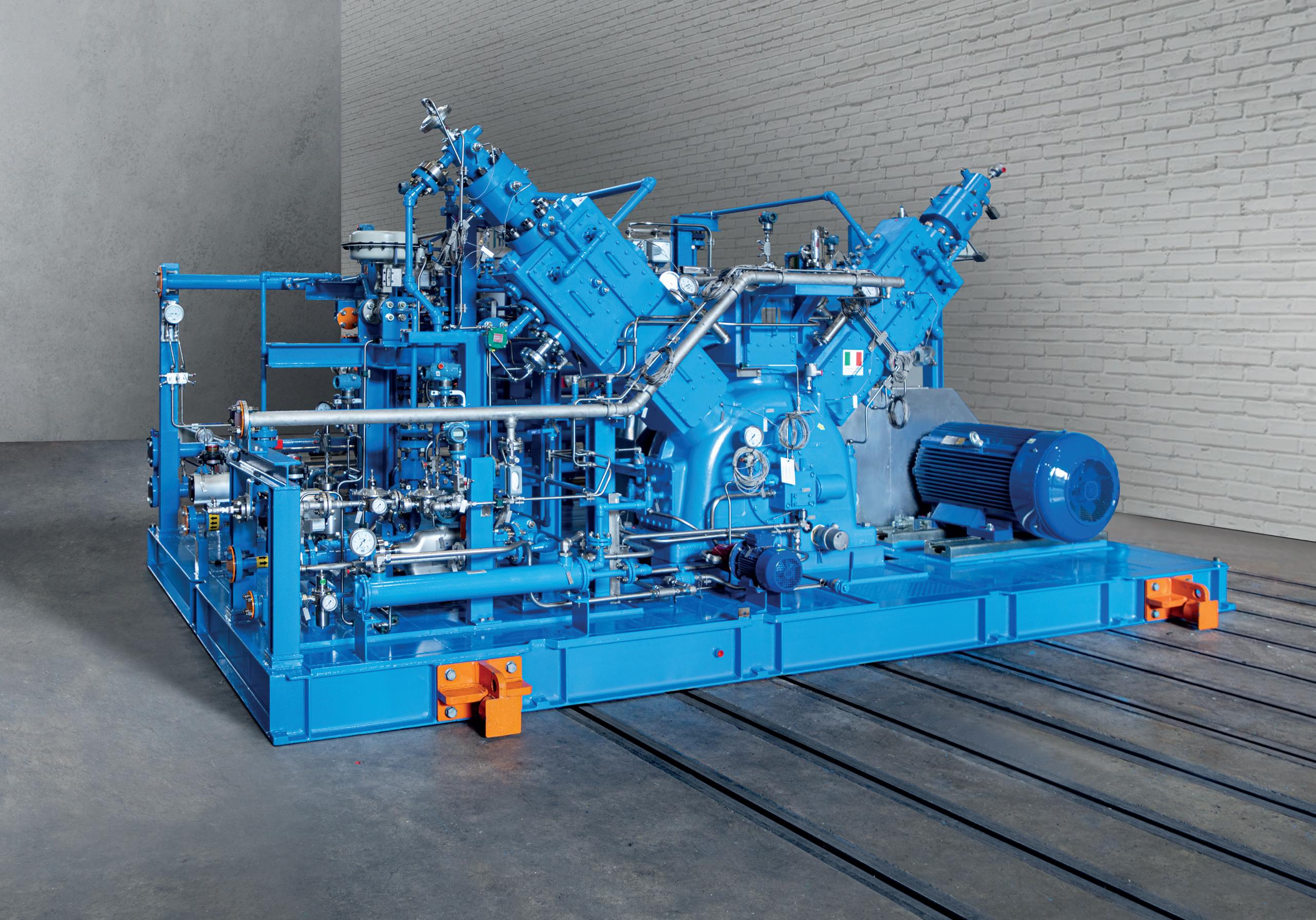

demand, support decentralised energy models, and accelerate the deployment of clean fuel solutions across diverse sectors.
Fabrum’s collaboration with Fortescue at Christmas Creek, Australia represents a pivotal move in hydrogen infrastructure development. The project delivered the world’s first LH2 production system at an operational mine site, designed to produce 450 kg/d of LH2 and support zero-emissions mining vehicles including a hydrogen-powered haul truck and offboard power unit providing a mobile electricity supply to electrically powered equipment.
This case study showcases an end-to-end LH2 production and supply chain, including:
y A ruggedised, containerised LH2 plant.
y Mobile refuelling infrastructure.
y Onboard vehicle tanks with inbuilt technology to convert LH2 to gaseous hydrogen for fuel-cell supply.
Fabrum’s proprietary cryocooler technology, based on a pulse-tube system, enables autonomous operation with the only inputs being electricity and gaseous hydrogen – eliminating the need for pre-cooling with liquid nitrogen. The pulse-tube cryocooler offers several key advantages for remote and industrial applications:
y Reduced maintenance: with no moving parts in the cold head, the system minimises mechanical wear and tear, significantly lowering maintenance requirements and extending service intervals.
y High reliability: its robust design ensures consistent performance in harsh environments, making it ideal for remote mining operations like Christmas Creek.
y Modular: the cryocooler’s compact footprint supports Fabrum’s modular infrastructure approach, allowing for easier deployment and scalability.
y Energy efficiency: optimised for low-power consumption, the system aligns with sustainability goals by reducing the overall energy footprint of hydrogen liquefaction.
This project demonstrates that small scale hydrogen systems are not only technically viable but strategically essential. They offer a practical, scalable path to decarbonisation, bridging the gap between research and development (R&D) and full scale infrastructure by enabling the supply of LH2 today to support the proving out of early-stage technology and applications.
Small scale hydrogen liquefiers are an essential step in the advancement of the hydrogen economy. These systems provide a flexible, cost-effective, and scalable first step for supply of LH2. For LH2 to become a viable alternative to fossil fuels, there is significant development needed to prove out both technologies that will consume LH2, and the application use cases. LH2 is a critical input for this development, though at small scale. Thus, the technologies and products that support small scale LH2 production can be expected to be widely deployed in the coming years.
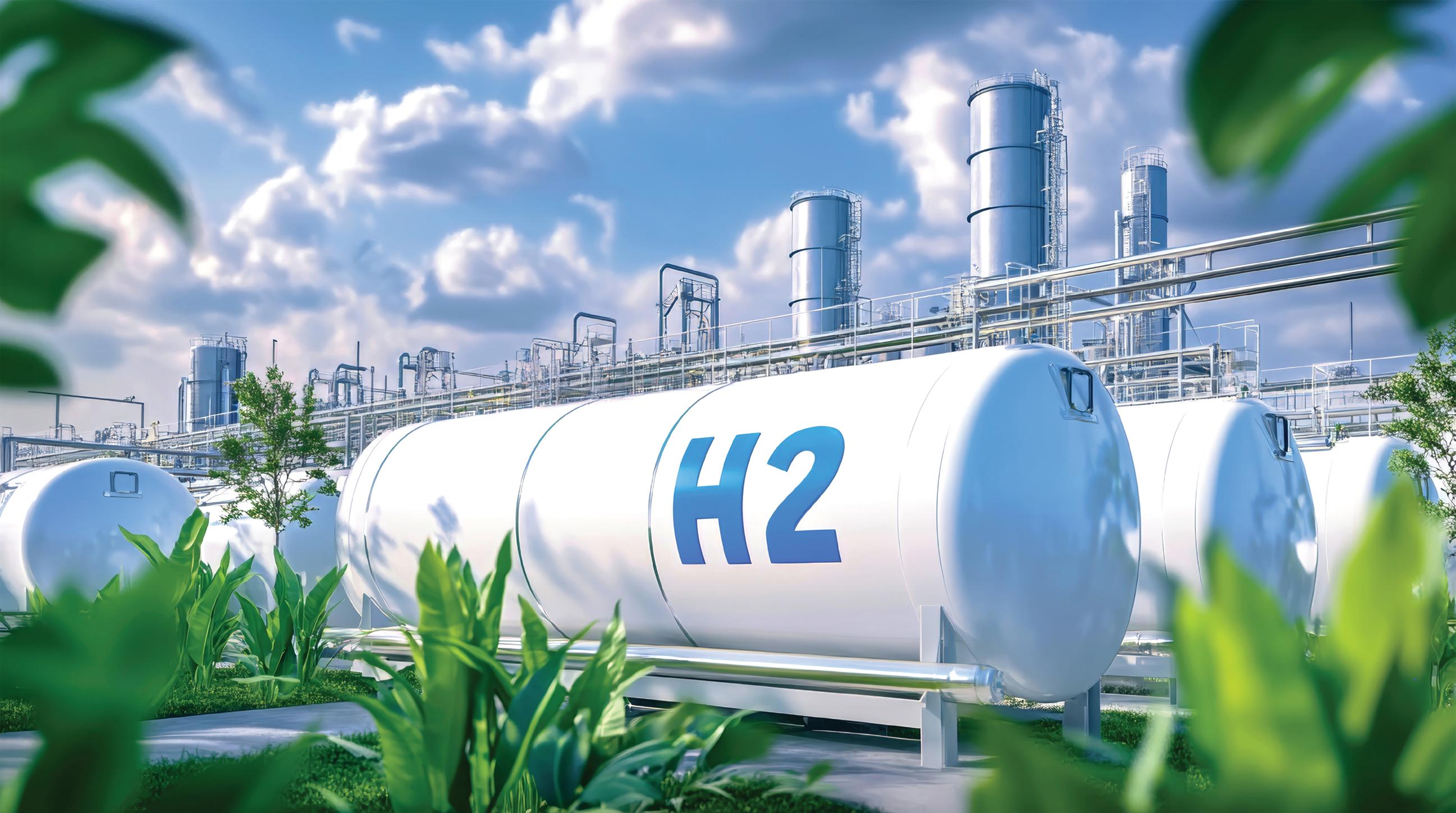
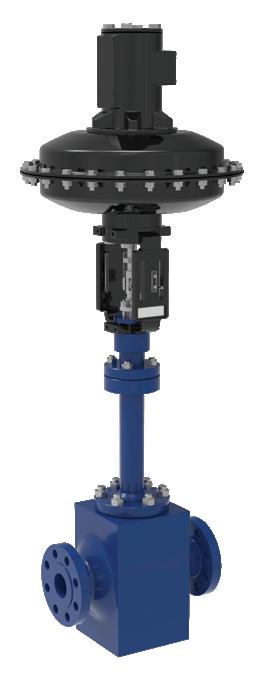
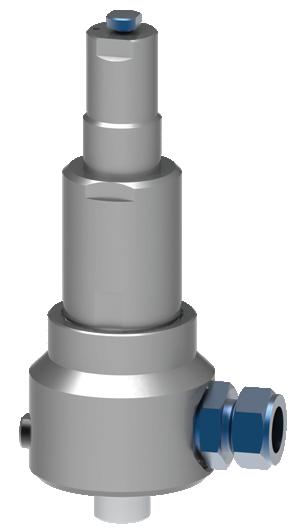

Andrzej Janowski, MSA Safety, Poland, discusses the safety considerations, challenges, and technology applications of hydrogen.
As industries continue to explore hydrogen as a viable energy carrier, the importance of comprehensive safety measures has come into sharp focus. While hydrogen offers several environmental and operational benefits, such as clean combustion and high energy density, its unique physical and chemical properties require a rethinking of conventional safety systems and detection methods.
This article outlines some of the critical safety considerations associated with hydrogen use, explores commonly applied detection technologies, and discusses key aspects of system design, standards, and maintenance for industrial and commercial applications.
Hydrogen presents specific hazards that differ from more traditional fuels. Although non-toxic and lighter than air, meaning it can disperse quickly in open environments, it remains a highly flammable and asphyxiant gas with a wide flammability range (4 - 77% by volume in air). Certain properties also make hydrogen especially difficult to detect:
y It is odourless, colourless, and invisible to the naked eye.
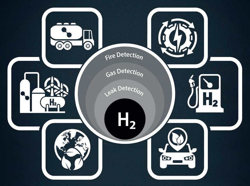
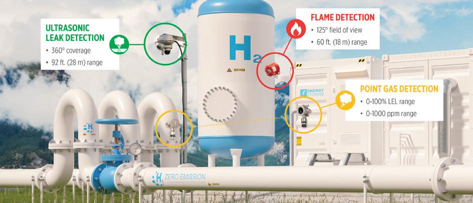
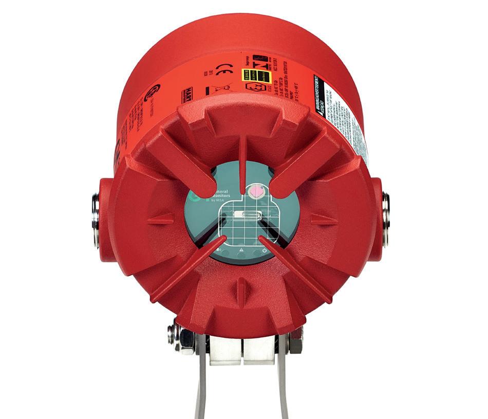
y It forms almost-invisible flames when burning, especially in daylight.
y It is lighter than air, and in confined spaces, it rises and may accumulate near ceilings, displacing oxygen.
y High-purity hydrogen used in applications like fuel cells cannot tolerate impurities such as added odorants.
These characteristics necessitate robust detection technologies that are capable of early identification of leaks or ignition events, even in challenging environments.
Various technologies are employed in industrial hydrogen detection systems, each with specific strengths and limitations. Effective safety strategies often rely on a layered approach that combines multiple sensing methods.
UGLD devices detect the high-frequency sound generated when pressurised hydrogen escapes through a leak. This technique does not rely on gas concentration or gas plume presence, making it well-suited for open or ventilated areas where hydrogen may dissipate rapidly. Because detection is based on sound, UGLD detectors are unaffected by wind direction and can respond almost instantly, at the speed of sound.
These devices detect flammable gases by oxidising them on heated beads (pellistors). The resultant change in electrical resistance is proportional to the gas concentration. Catalytic sensors are typically used in the 0 - 100% Lower Explosive Limit (LEL) range, which for hydrogen corresponds to 0 - 4% by volume in air. While effective in many settings, they require the presence of oxygen for catalytic reaction and may be less suited for outdoor detection of small leaks or very low concentrations.
Electrochemical cells measure gas concentration through chemical reactions that generate a measurable electric current. These are particularly sensitive and are used for detecting low concentrations of hydrogen, typically in the range of 0 - 1000 ppm. They offer a complementary solution to catalytic sensors, especially in enclosed or controlled environments where early detection is critical.
UV/IR flame detectors simultaneously monitor infrared (IR) and ultraviolet (UV) radiation at different wavelengths. When hydrogen burns, radiation is emitted in the infrared spectrum by hot water molecules or steam created by combustion. Combining UV and IR sensing reduces the likelihood of false alarms and enables reliable detection of hydrogen flames.
Hydrogen’s lack of a strong mid-infrared absorption band makes traditional infrared gas detectors ineffective for identifying hydrogen gas leaks. These sensors, commonly used for detecting hydrocarbons like methane or carbon dioxide, cannot reliably register the presence of hydrogen.

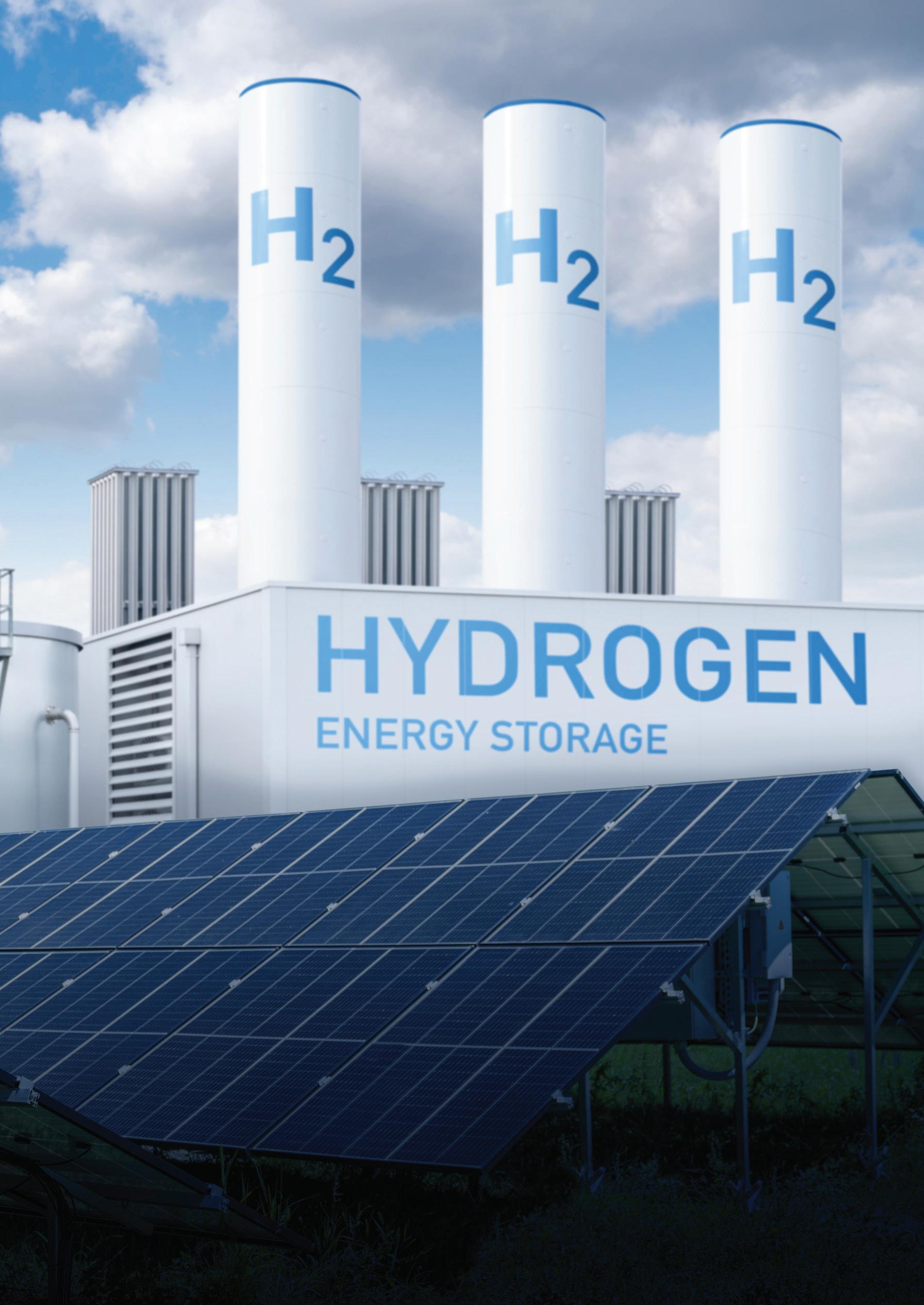
Hydrogen leaks and flames can be difficult to detect without the right technology. MSA’s advanced fire and gas detection systems can help mitigate risks and support a safer workplace. Explore Hydrogen Detection Solutions at msasafety.com/hydrogen-detection-solutions
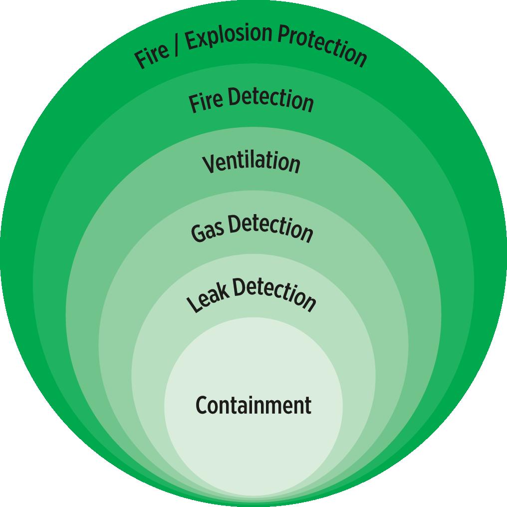
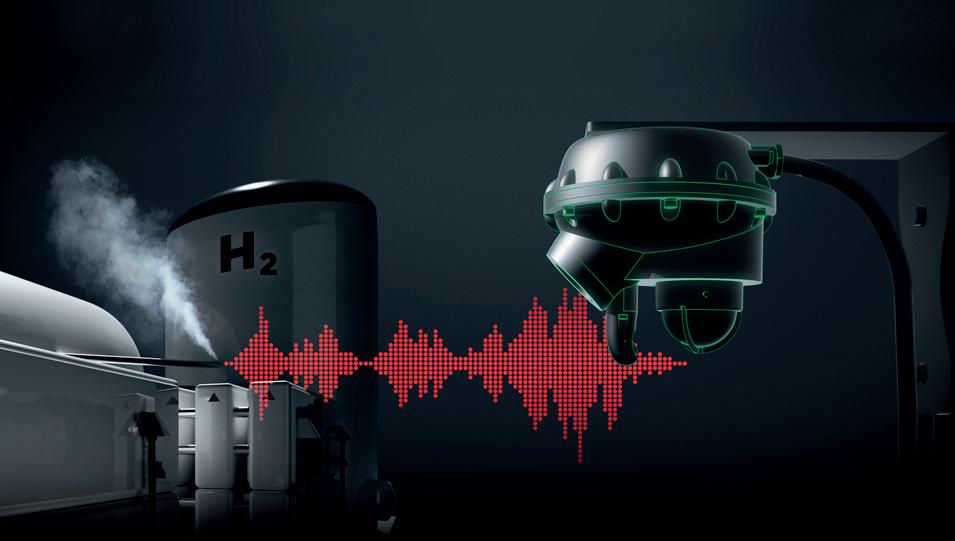
Modern hydrogen gas leak and fire detection systems often incorporate a combination of the above technologies. This multi-layered approach mirrors human senses: ultrasonic detectors ‘hear’ leaks, point sensors ‘smell’ gas concentrations, and optical sensors ‘see’ flames. Together, they help to increase the chance of early and reliable detection.
Controllers or safety systems to which these detectors are connected can be configured to initiate predefined safety actions, such as equipment shutdowns or ventilation activation, based on real-time measurements.
Correct sensor placement is essential for achieving effective coverage. Hydrogen’s buoyancy and potential to form gas jets under pressure mean that gas dispersal can be unpredictable. Point detectors placed inappropriately may miss leaks entirely, especially in open or ventilated spaces. Plume modelling and gas mapping software tools can help illustrate detector effectiveness and guide optimal detector positioning.
International and sector-specific standards are shaping explosion protection, gas detection, and risk mitigation practices in hydrogen-related operations.
Fire and explosions are the main safety considerations associated with handling hydrogen, especially considering its wide flammability range of 4% to 77% of volume in air. Explosion protection is currently governed internationally by the IEC/EN/ISA 60079 and ISO/IEC 80079 standards, with many regions adopting similar standards locally. Additionally, specific international standards for hydrogen facilities are also in place.
For example:
y ISO 22734 – Hydrogen generators using water electrolysis – Industrial, commercial, and residential applications: requires manufacturers of electrolysers to perform a risk assessment. Depending on the final placement location of the equipment, plant owners and operators may need to perform an additional assessment on the hydrogen generator, applying zone classification using IEC 60079-10-1 or an appropriate national standard.
y ISO 19880 – Gaseous hydrogen – Fuelling stations: requires that sites must be inspected in accordance with the IEC 60079-10-1 standard or sufficient national regulations. This includes zone classification and ignition protection methods to IEC 60079, ISO/IEC 80079 and NFPA 2.
Both ISO 22734 and ISO 19880 standards also specify requirements for risk mitigation, with gas detection system as one of the methods to prevent the accumulation of ignitable gas mixtures. However, these standards do not give detailed guidance about the selection or installation of gas detectors. Organisations often choose to follow the more specific guidance in the IEC/EN/ISA 60079 series of standards to help ensure that their fixed hydrogen gas detection systems are properly specified, installed, and maintained to enhance safety in hazardous environments.
The reliability of any hydrogen detection system depends on proper maintenance. Guidelines such as IEC/EN 60079-29-2 provide recommendations on the selection, installation, and upkeep of detection systems for flammable gases and oxygen. In addition to manual inspection routines, some detectors now feature inbuilt self-test functions. For instance, ultrasonic sensors may perform integrity checks on their microphones and electronic components at regular intervals. Some flame detectors can monitor their optical paths for obstructions like dust or ice, triggering a fault alarm if interference is detected. These automated diagnostics help reduce the risk of undetected device failure and enable a proactive maintenance approach.
Ventilation and air movement serve two primary purposes as per IEC 60079-29-2 standard:
y Enhancing dilution and promoting dispersion to limit the extent of hazardous gas areas.
y Preventing the persistence of explosive atmospheres, which could influence the hazardous area classification.
The ventilation rate must be evaluated in comparison to the expected flammable gas leakage rate under various operational
conditions. This relative comparison determines how flammable gas detection systems and ventilation should operate together. Detailed guidance on assessing ventilation efficiency and availability is provided in IEC 60079-10-1, Annex B.
Gas detection systems can implement safety functions, including:
y Disconnecting non-explosion-protected equipment if gas levels exceed the alarm threshold.
y Increasing ventilation rates to prevent gas concentrations from exceeding the defined level at the equipment location.
Additional requirements are outlined in standards such as ISO 22734 and ISO 19880. These standards address specific safety, reliability, and performance aspects of hydrogen production, storage, and distribution systems.
Recent innovations in hydrogen detection focus on improving sensitivity and reducing false alarms. Advanced ultrasonic detectors now use Artificial Neural Networks (ANNs) to differentiate between actual gas leak sounds and background noise. Some devices can detect hydrogen leaks from distances up to 28 m, without the need for pre-set trigger levels or extensive setup procedures.
These developments, coupled with improved algorithmic processing and self-monitoring capabilities, reflect a growing effort to improve detector reliability in complex operational environments.
When selecting hydrogen detection systems, both the physical environment and the operational context are important. Factors, such as gas pressure, ventilation, potential leak sources, and the presence of other flammable substances, should inform technology selection and detector placement.
In many cases, a hybrid solution that integrates point gas sensors with ultrasonic and optical flame detectors can provide a more robust detection system. Fire and gas mapping tools and gas plume modelling can further help in identifying potential blind spots and optimising coverage.
Hydrogen safety is a complex but manageable challenge. By understanding its unique properties and applying a layered detection strategy, operators can significantly reduce risks in production, storage, and distribution environments.
Ongoing improvements in sensor technology, signal processing, and system integration continue to enhance the reliability of hydrogen detection systems. As hydrogen applications expand across sectors, proper design, implementation, and maintenance of these systems will remain a cornerstone of safe industrial practice.


Garry Hanmer, Atmos International, UK, explores some of the challenges facing hydrogen transport through pipelines, and how to implement solutions for safe and reliable operations.
As the world accelerates efforts to decarbonise, hydrogen is emerging as a critical energy carrier, enabling the large scale transport of renewable energy. From Europe, North America, Asia-Pacific, and beyond, hydrogen pipelines are becoming an essential component of the energy transition.
While European developments, such as Belgium’s pipeline delays, the UK-Germany collaboration, and Greece’s tender for a hydrogen pipeline to Bulgaria, have received significant attention, the technical and regulatory challenges they face are not confined to Europe. Pipeline operators around the world must address these challenges to ensure the safe, efficient, and sustainable transport of hydrogen.
There are many technical and regulatory hurdles to overcome to ensure that hydrogen pipelines meet the highest standards of safety and performance. This article will explore some of the solutions that Atmos International provides to support this transition, drawing on the company’s experience in pipeline simulation and leak detection.
In Belgium, the flagship hydrogen pipeline project has encountered a year-long delay due to complex permitting and stakeholder processes.1 This highlights a universal challenge: regulatory frameworks for hydrogen infrastructure are still evolving. Operators worldwide face similar complexities that demand technical readiness and a deep understanding of local regulations.
Digital simulation and monitoring solutions can provide operators with data-driven insights. These solutions help operators comply with diverse regulatory frameworks and mitigate risks, whether in Europe, North America, or Asia-Pacific.
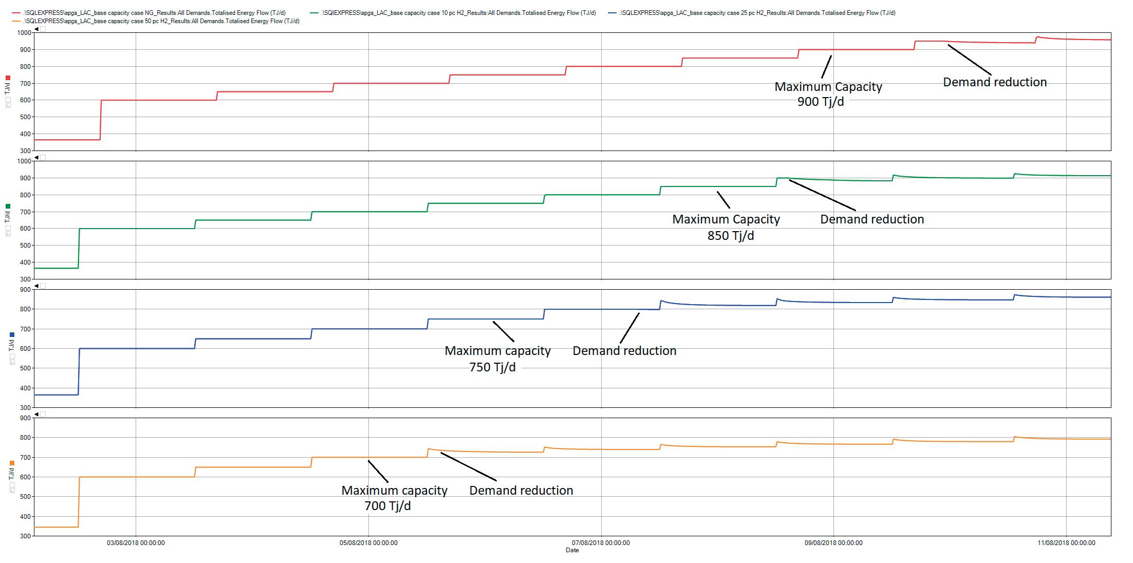
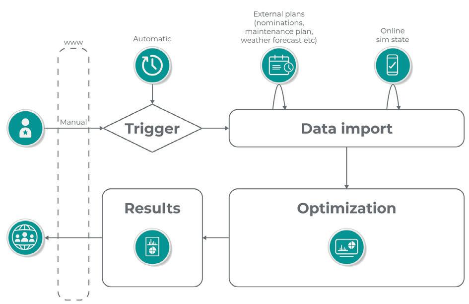
collaboration: the UK-Germany partnership
The UK and Germany’s recent agreement to collaborate on an offshore hydrogen pipeline and to explore a direct pipeline connection exemplifies the complexity of cross-border integration.2,3 Differences in national regulations, operational standards, and safety requirements necessitate adaptable solutions that enable safe and efficient cross-border transport.
Pipeline simulation software provides a comprehensive solution involving real-time monitoring and simulation capabilities to support safe, efficient, and compliant operations across borders, regardless of local regulations or operational practices.
Greece’s tender for a hydrogen pipeline to Bulgaria demonstrates the importance of regional integration in developing a resilient hydrogen network.4 Projects like this are essential to connecting supply and demand centres, promoting market liquidity, and enhancing energy security.
Transient flow modelling and capacity analysis enables operators to design and manage such networks effectively. Through simulation and real-time data integration, it is
possible to ensure that operators can plan for fluctuating demand, supply variability, and regulatory requirements.
embrittlement: a universal risk
Hydrogen embrittlement presents a significant risk to pipelines worldwide. Hydrogen can permeate steel, leading to embrittlement, cracking, and ultimately pipeline failure.5 On a 160 km pure hydrogen pipeline, Atmos demonstrated the critical role of simulation in mitigating embrittlement risks.
By using the GERG-2004 equation of state and conducting rigorous model tuning, the company achieved simulation results with a deviation of just 0.5% compared to measured flowrates, ensuring high accuracy in predicting pipeline behaviour.6
Hydrogen’s lower energy density compared to natural gas means that repurposed pipelines can experience significant capacity reductions.
Simulation software can enable operators to model these impacts accurately (see Figure 1), providing the data required for investment decisions, operational planning, and stakeholder engagement.
Atmos’ simulation tools can support hydrogen pipelines worldwide. For example, Atmos Simulation (SIM) Suite provides offline and online simulation functionalities that enable operators to plan, analyse, and monitor pipelines across their lifecycle. Offline modules support steady-state and transient analysis, operator training, and capacity studies, while online modules offer real-time monitoring of pressure, flow, and gas quality (see Figure 2).
This versatility ensures that the tool is adaptable to diverse operating environments, from Europe’s interconnected grids to emerging hydrogen networks in North America, Asia-Pacific, and beyond.
Delivering hydrogen that meets quality standards is critical for all operators. Atmos SIM’s gas quality module enables operators to monitor key parameters, including hydrogen concentration, heating value, and CO2 levels. This supports regulatory
Mokveld supplied the first valves for hydrogen applications over 30 years ago. At present our axial control valves, on-off valves and check valves are operating in various H2 applications. This includes pure H2 and mixes, like syngas.
Mokveld axial flow valves are lower in weight and in many cases smaller valves can be used than with other valve types. This results in low energy consumption to produce Mokveld valves and therefore lower GHG Scope 3 emissions for our clients.
The one piece body casting of our axial valves reduces the number of leak paths to atmosphere versus many other body-designs. Our Zero Emission Valve even eliminates the dynamic seal to atmosphere thus assuring a lifetime zero emission to atmosphere. Less leak paths not only reduces emissions, but also increases safety.
Historically Mokveld axial valves are found in syngas applications in the Steam Methane Reforming (SMR) process, the hydrogen flow in refineries and fertiliser plants and in the ammonia flow in chemical plants. The minimum pressure loss, perfect tight-shut-off and excellent controllability is highly appreciated by our clients.
Recently new applications are seen. At the outlet of the electrolyser a high integrity safety valve is required to avoid pressure and flow to return from the compressor into the electrolyser. In the production, transport and storage of hydrogen Mokveld over-pressure protection systems, often with mechanical initiators are installed to protect equipment and personnel.
Hydrogen appears as H2, H alone is the smallest molecule. Although H2 is slightly bigger than for example Helium it is still very small. Therefore attention shall be paid to leakage to atmosphere. Also while H2 could be considered a GreenHouse Gas, the 20 year Global Warming Potential is over 30 times that of CO2
Testing for leakage could be performed with Helium. While Helium is finite in the world we prefer to use forming gas (5% H2 + 95% N2) as a safe and sustainable alternate. API 6D Annex M covers forming gas as well.
Hydrogen may cause material degradation, such as embrittlement, but also may degrade surface treatments. Therefore the correct material selection is highly important and dependent of the specific application. (Partial) pressure, temperature, presence of water etc. has an impact on the proper selection. Mokveld can supply the proper material for your application
Mokveld is involved in European (EN), American (API, ASME) and international (IEC) standardization committees to closely follow the developments and advise the best solution for you.

compliance and ensures that end users receive products that meet contractual specifications.
Hydrogen and natural gas blends need to be accurately modelled across the full range, from 0 - 100% hydrogen. Many older simulation packages rely on equations of state such as Peng Robinson or Benedict Webb Rubin, which are based on the critical properties of individual components and do not include interaction coefficients for hydrogen.
Modern cubic equations, such as GERG-2004, are specifically fitted to the behaviour of mixtures, including hydrogen blends, and are a better choice for accurate and reliable gas quality forecasting.6
Atmos SIM can model hydrogen blends accurately for both gas transmission and distribution networks. It is an ideal choice for real time calorific value calculations as more hydrogen and biomethane are introduced to gas networks.
Model tuning: aligning digital models with real-world conditions
Atmos’ model tuning process aligns simulations with actual pipeline behaviour. By calibrating factors such as pipeline roughness and heat transfer, operators achieve simulations that match operational data, with deviations of just 0.05% compared to measured flowrates. This accuracy is essential for reliable capacity forecasts, risk assessments, and contingency planning.6
The global hydrogen economy demands solutions that are technically advanced, operationally reliable, and adaptable to diverse regulatory and environmental conditions. While Europe
currently serves as a high-profile testbed for hydrogen pipelines, the lessons learned there apply globally. Challenges such as hydrogen embrittlement, capacity constraints, and regulatory complexity are not confined to any one region.
Atmos is committed to supporting operators worldwide with advanced simulation tools, leak detection systems, and regulatory expertise. By utilising such technology at every stage, from planning to operations, pipeline operators can build and operate hydrogen infrastructure that meets the highest standards of safety, efficiency, and sustainability.
1. HELM, U., ‘Year-long delay to Belgium’s hydrogen pipeline project: is there legal recourse?’, New Civil Engineer, (9 May 2025), https://www. newcivilengineer.com/opinion/year-long-delay-to-belgiums-hydrogenpipeline-project-is-there-legal-recourse-09-05-2025/
2. HABIBIC, A., ‘UK and Germany shake hands on offshore hydrogen pipeline’, Offshore Energy, (22 May 2025), https://www.offshore-energy. biz/uk-and-germany-shake-hands-on-offshore-hydrogen-pipeline/
3. ‘Germany and UK strengthen energy partnership with planned offshore hydrogen pipeline connection between the two countries’, GASCADE, (22 May 2025), https://www.gascade.de/en/press/press-releases/pressrelease/germany-and-uk-strengthen-energy-partnership-with-plannedoffshore-hydrogen-pipeline-connection-between-the-two-countries
4. ONYANGO, D, ‘Greece launches tender for hydrogen pipeline to Bulgaria, boosting EU clean energy goals’, Pipeline Technology Journal, (23 May 2025), https://www.pipeline-journal.net/news/greece-launchestender-hydrogen-pipeline-bulgaria-boosting-eu-clean-energy-goals
5. ‘Using simulations tools to support the transition to hydrogen for both new and existing pipelines’, Atmos International, https://www.atmosi. com/en/resources/technical-papers/using-simulation-tools-to-supportthe-transition-to-hydrogen-for-both-new-and-existing-pipelines/
6. HANMER, G., ‘Hydrogen’s pure potential’, World Pipelines, (June 2024), https://www.atmosi.com/media/vfjjv3bp/atmos-international-worldpipelines-june-2024-article.pdf

Register for free at www.energyglobal.com
Suji Kurungodan and Dr Andrew Stevenson, Sustainable Pipelines Ltd, discuss a shift to usher in the net zero era with intelligent, flexible, high-performance pipeline network infrastructure.
As the world transitions to cleaner energy sources, hydrogen has emerged as a cornerstone of decarbonisation strategies across industrial sectors. Its ability to store energy, decouple production from consumption, and power high-intensity applications makes hydrogen a critical enabler of net zero ambitions. However, the infrastructure needed to distribute hydrogen safely,

efficiently, and at scale remains a formidable challenge. At the heart of this challenge lies the need to reinvent the pipeline industry.
The traditional pipeline infrastructure, built around rigid girth welded steel assets, environmentally
intensive construction engineering, and periodic condition monitoring regimes, is no longer fit for the evolving demands of the hydrogen energy ecosystem. The sector now faces a confluence of factors: the introduction of hydrogen and CO2 transport, increasing environmental and safety expectations, growing exposure to climate-induced geohazards, and the need to reduce lifecycle emissions. Against this backdrop, a new generation of pipeline systems must emerge – one that is faster to install, digitally intelligent, more flexible, and inherently safer.
The pipelines of the future must combine high-pressure capabilities with resilience to ground movement, incorporate real-time condition monitoring, and be deployable with minimal carbon footprint. Automated in-field manufacture of flexible reinforced polymer pipelines, embedded with helically wound optical fibres, offers a pathway to meet these ambitious goals. These smart pipeline systems integrate continuous quality control, digital twin readiness, and future-proof compatibility with hydrogen and carbon dioxide service.
Climate change is intensifying threats to buried pipelines by altering environmental and soil conditions. Extreme rainfall, rising groundwater, freeze-thaw cycles, drought-induced shrinkage, and soil liquefaction degrade soil strength and increase ground movement events like landslides and erosion. These dynamic loads impose complex mechanical strains on girth welded rigid steel systems, leading to bending, buckling, and reduced fatigue life. High-pressure, large-diameter pipelines are particularly at risk, as girth welds concentrate stress, and small cracks can evolve into catastrophic fractures. Without historical stress-strain data, assessing fatigue life becomes challenging, especially in ageing networks. Traditional monitoring methods, such as visual surveys or discrete strain gauges, often fail to detect early-stage ground disturbances. Consequently, the risk of pipeline deformation, loss of containment, or failure is rising, highlighting the urgent need for continuous, distributed sensing technologies that can identify mechanical threats in real time and improve predictive maintenance strategies.
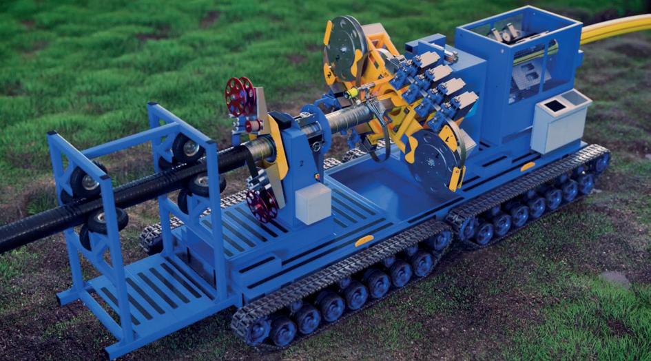
A flexible steel strip reinforced thermoplastic pipe (SRTP) system, designed for high-pressure applications and manufactured in-field along the pipeline right-of-way, offers a transformative approach to future pipeline infrastructure. Unlike traditional steel pipelines, which require extensive welding and rigid logistics, in-field SRTP systems enable continuous production and direct trench installation –reducing construction time, environmental impact, and health and safety risks. The composite structure, combining corrosion-resistant polymers with high-strength steel reinforcement, delivers high burst resistance, fatigue durability, and flexibility to withstand ground movement and geohazards such as subsidence or differential settlement. Its ability to accommodate tight bend radii without yielding enhances resilience in challenging terrains, increasingly impacted by climate change. The polymer barrier is inherently immune to hydrogen embrittlement and CO2 corrosion, ensuring long-term compatibility with net zero fuels. Moreover, helically embedded optical fibres enable continuous, real-time distributed sensing, turning the pipeline into a self-monitoring, intelligent asset. This integration of advanced materials, flexible deployment, and embedded sensing makes high-pressure RTP systems an optimal, future-proof solution for building smart, sustainable, and safer energy networks.
The integrity management of buried high-pressure pipelines in the UK has long depended on a multi-layered regime guided by IGEM/TD/1 or industry guidance, incorporating line walking, aerial and above-ground surveys, in-line inspections (ILI), Pipeline Integrity Management Systems (PIMS), and SCADA systems. While these methods have ensured a baseline level of safety, they are increasingly insufficient in the face of ageing infrastructure, climate-induced geohazards, and the hydrogen transition, which poses heightened risks of embrittlement cracking, fatigue failures, and running ductile fractures.
The key limitation of traditional approaches lies in their reliance on spatially and temporally discrete data. SCADA systems provide continuous monitoring, but only at fixed sensor locations. In contrast, surveys and ILI are periodic, often conducted annually or less frequently, offering only ‘snapshots’ of asset condition. This leaves significant blind spots in threat detection, particularly for emerging risks between inspection intervals.
Moreover, conventional methods typically infer pipeline stress or strain indirectly. For instance, ILI may reveal geometry changes such as dents or ovality, suggesting strain, but without quantifying it. External indicators, like soil displacement or erosion, are observational and cannot confirm mechanical loading on the pipeline. This lack of direct strain measurement is a critical gap, especially for hydrogen pipelines, where embrittlement and fatigue crack growth demand real-time structural insight.
A paradigm shift to predictive, data-driven integrity management is now essential. This requires continuous,
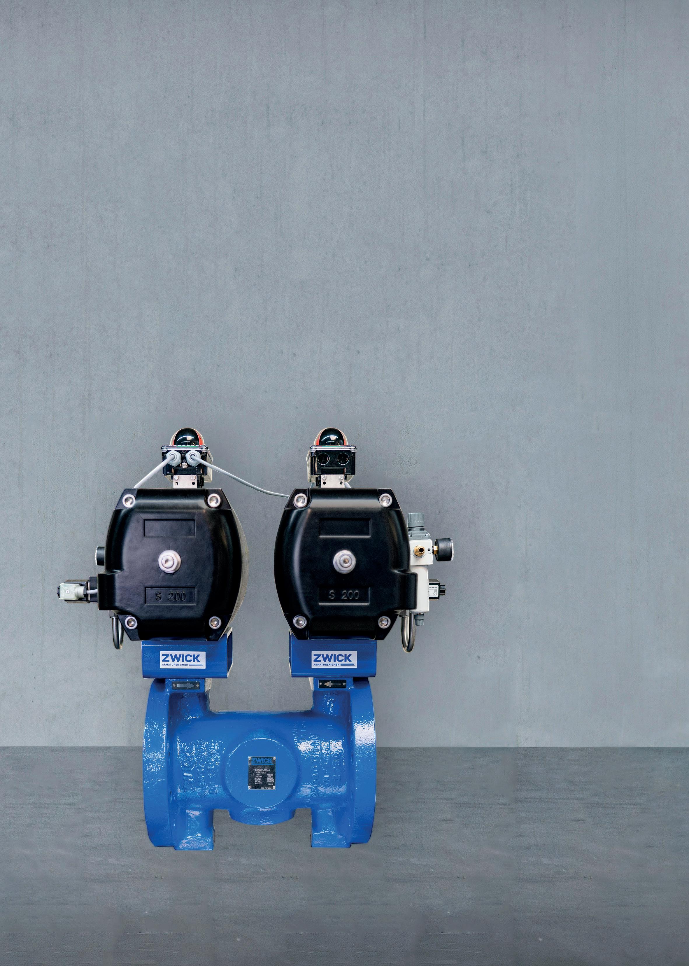
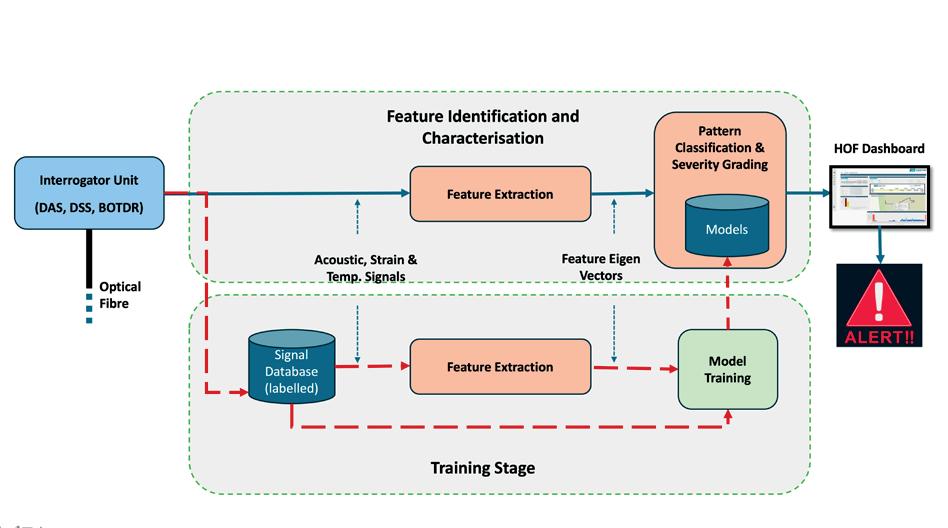
Figure 2. Typical architecture of an AI-enabled threat detection and classification system for pipeline threat monitoring based on optical fibre response patterns.
real-time monitoring using distributed optical fibre sensing systems embedded along the pipeline. Technologies, such as Distributed Acoustic Sensing (DAS), strain sensing, and Brillouin Optical Time Domain Reflectometry (BOTDR) offer high-resolution, full-length data on strain, vibration, temperature, and acoustic emissions. These systems can detect a wide range of threats including:
y Ground movement (e.g. landslides, subsidence).
y Pipeline deformation (e.g. buckling, upheaval).
y Third-party interference.
y Integrity anomalies (e.g. dents, corrosion, fatigue).
y Leaks and pressure surges.
By capturing both global and localised behaviour, fibre-optic sensing transforms pipeline monitoring from reactive to proactive – forming the backbone of a next-generation PIMS that anticipates failures before they occur and reduces reliance on periodic inspections.
While distributed sensing solves the visibility challenge, the next hurdle is managing and interpreting the vast volumes of complex signal data generated. Here, Artificial Intelligence (AI) and Machine Learning (ML) become indispensable. A fully automated, AI-enabled integrity management system transforms raw fibre-optic data into actionable intelligence. The architecture of such a system comprises several key components:
The proposed architecture for an AI-enabled threat detection and classification system represents a transformative leap in the field of pipeline integrity management, particularly for networks transporting critical net zero fuels such as hydrogen and CO2. At its core, the system integrates helically embedded optical fibre sensors – capable of capturing DAS) and BOTDR data with a multi-layered AI framework that automates the full cycle from signal acquisition to decision support.
The architecture begins with a Signal Acquisition Module, enabling continuous high-fidelity streaming of acoustic, temperature, dynamic and static strain data along the entire pipeline length. This is followed by
a Feature Extraction Engine, which applies advanced signal processing routines across time, frequency, and time-frequency domains to capture the physical signatures of pipeline threats, leaks, operational surges, ground movement, mechanical impacts, and structural deformation. These features are then fed into a pattern classification module, where supervised machine learning algorithms e.g., CNNs, LSTMs or GRUs are trained on threat-labelled datasets derived from controlled simulations. This enables rapid and accurate classification of complex threat types such as landslides, pipe upheaval, erosion, leaks, or third-party interference. The Severity Grading Module maps these outputs to quantitative risk scores through ordinal classification or probabilistic regression, while incorporating contextual variables such as threat duration, intensity, proximity to critical infrastructure, and baseline signal variation.
To ensure actionable reliability, the system incorporates a Confidence Scoring and Decision Support Layer. This facilitates a scalable yet interpretable framework, enabling human oversight where necessary, while maintaining full automation in routine operation.
Such an architecture would support a first-of-its-kind PIMS, capable of detecting and classifying pipeline defects in real time for the full pipeline length, with over 90% accuracy within just 10 minutes, eliminating the need for manual interpretation of vast, complex signal datasets.
A particularly transformative innovation is the development of predictive integrity models that learn from real and synthetic data derived from full scale threat simulations. By training ML algorithms on controlled pipeline deformation scenarios, these systems can recognise early-stage anomalies that might precede failure. Once trained, the AI system can classify events and assign severity scores within minutes of occurrence – a significant leap from traditional inspection cycles.
Such predictive models provide several strategic advantages:
y Early warning and rapid response to emerging geohazards.
y Quantitative risk-based prioritisation of field interventions.
y Reduction in false positives and false negatives through contextual scoring.
y Dynamic risk mapping and digital twin visualisation.
y Reduction in manual data analysis burden on operators.
When paired with reinforced flexible pipelines, this intelligent system forms the foundation of a fully autonomous, self-aware pipeline network.
The recent integration of SCADA sensor data into the Pipeline Open Data Standard (PODS) via the new SCADA Link module represents a pivotal advancement in pipeline data management. By tying physical sensor locations directly to geospatial asset records, this linkage significantly enhances audit compliance, operational visibility, and decision-making
COMPLETE COMPRESSION & CONTROL SOLUTION INSTALLED IN CONTAINER
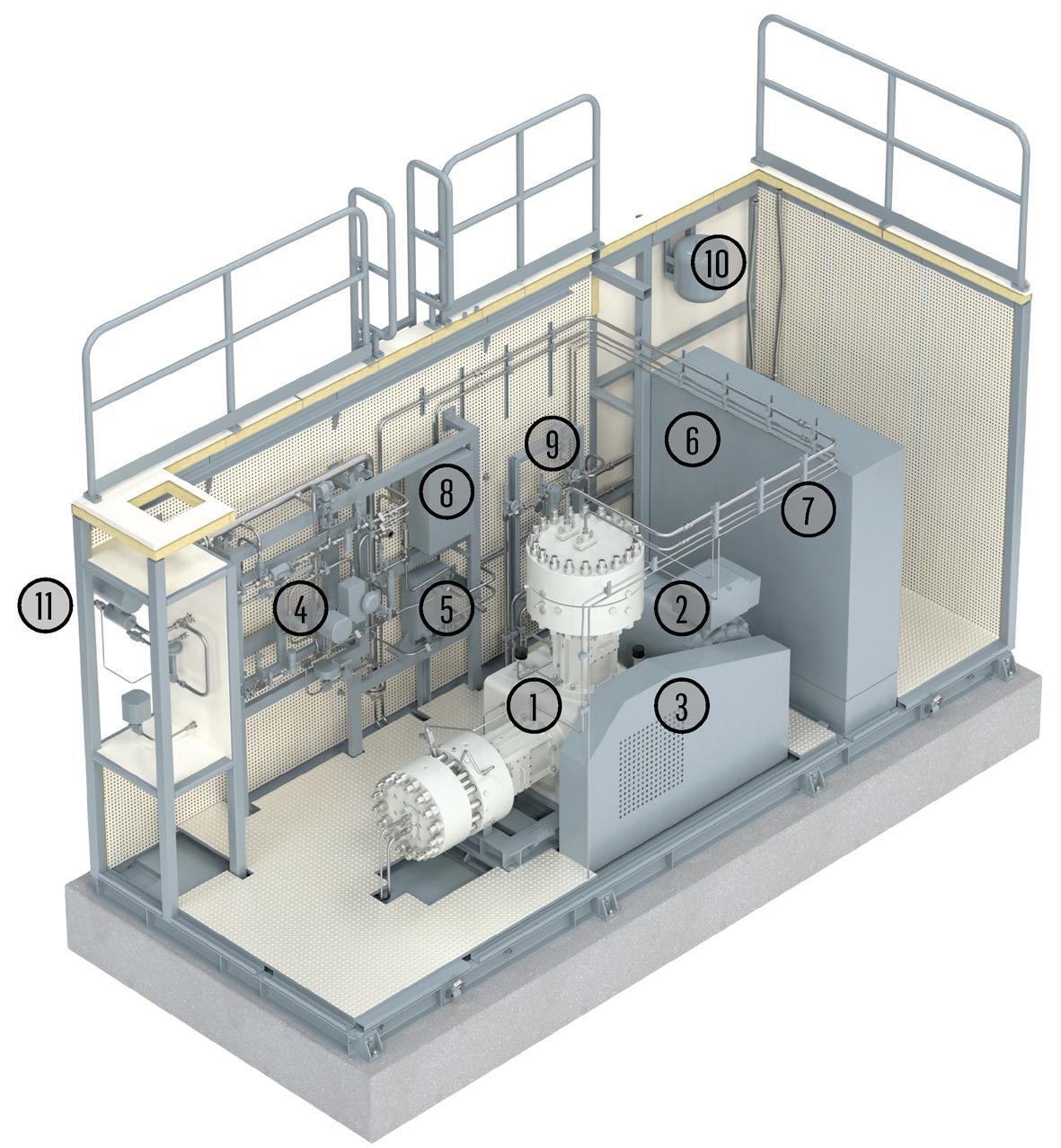
Legend:
1) Diaphragm compressor
2) Electrical main drive (motor)
3) Transmission
4) Process gas system
5) Process gas heat exchanger
6) Control system
7) MCC
8) Remote IOs
9) Lube oil system
10) Cooling water system
11) Main system interfaces on back side of container
Hydrogen fuel stations for light and heavy-duty vehicles demand a large amount of hydrogen.
Shipped in GH2 trailers, the high amount of hydrogen requires compression solutions with a sufficiently flow.
To serve the fast growing need of such applications, with a easy to realize compression solution, Burckhardt Compression has partnered with multiple integrators and endcustomers and developed a standardized containerized solution exactly for this application.
Diaphragm compressors are oil-free and as such a proven solution for H2 trailer filling applications. Delivering hydrogen in the highest purity. Exactly as required by the fuelcells deployed within hydrogen powered vehicles.
• Fully standardized unit including PLC
• Optimized for 2.5 MW electrolizer capacity
• Skidded and container-installed compression solutions
• Pre-tested plug & play
• Highest hydrogen purity due to oil-free highpressurecompression according to SAE J-2719
• Leakage-free hydrogen compression
• Explosion-proof certification
• Full range of after-sales services
• Global network of local service centers


burckhardtcompression.com/hydrogen
Burckhardt Compression offers compressor solutions over the entire value chain of hydrogen for mobility and energy. Our oil-free diaphragm and piston compressors (550 bar) stand for the highest reliability and gas purity at minimal maintenance costs and energy consumption. The global network of Burckhardt Compression local service centers enables us to perform local support with quick response time, ensuring the highest uptime for your business.
accuracy for pipeline operators. It bridges the gap between real-time process control systems and spatially enabled asset databases, empowering advanced capabilities, such as automated flow calibration, route optimisation, and integrity tracking through standardised data governance.
However, to truly unlock the vision of a next-generation, real-time PIMS, it is imperative to extend this integration to include advanced real time sensing/streaming data formats, specifically the Production Markup Language (PRODML) standard widely used for optical fibre-based distributed sensing technologies, such as DAS and Distributed Temperature Sensing (DTS). These sensing modalities are increasingly employed in modern pipeline networks to capture high-resolution, continuous, and distributed measurements of acoustic, strain, and thermal variations along the entire pipeline length. As this class of real-time integrity data is natively structured and transmitted in PRODML format, its seamless ingestion into PODS is essential for creating a unified data ecosystem.
Integrating PRODML into the PODS data model would enable direct mapping of real time fibre optic measurements to spatial asset locations and associated attributes, allowing anomaly detection algorithms, machine learning tools, and digital twin platforms to operate on a complete, temporally and spatially synchronised dataset. This fusion of SCADA, PODS, and PRODML effectively lays the foundation for a predictive integrity framework capable of continuously monitoring the pipeline’s condition, detecting early threats such as ground movement, fatigue, leaks, or deformation, and generating actionable insights in real time.
To meet the technical demands of hydrogen transport, future pipelines must also address material compatibility and lifecycle performance. Polymer-based liners are inherently resistant to hydrogen embrittlement and internal corrosion. Reinforced thermoplastic or composite pipelines with embedded optical fibres offer both high-pressure capacity and mechanical flexibility, enabling tighter bend radii and better resilience to ground shifts.
Automated in-field manufacturing technologies further accelerate deployment timelines and reduce environmental impact. Integrated QC systems embedded in the manufacturing process ensure traceability and quality assurance across every metre of pipeline. These attributes are critical as hydrogen infrastructure expands across varied terrains and geographies.
As hydrogen takes centre stage in the global energy transition, the pipeline infrastructure that supports it must evolve radically. The integration of flexible, high-pressure SRTP pipelines with real-time distributed sensing and intelligent threat analytics represents a paradigm shift in pipeline design, operation, and maintenance.
This vision transforms buried pipelines from passive assets into active, intelligent components of a smart hydrogen grid capable of sensing, thinking, and responding. The result is a safer, more resilient, and lower-carbon infrastructure ready to support the hydrogen economy of tomorrow.