International Research Journal of Engineering and Technology (IRJET) e-ISSN: 2395-0056

Volume: 09 Issue: 09 | Sep 2022 www.irjet.net p-ISSN: 2395-0072

International Research Journal of Engineering and Technology (IRJET) e-ISSN: 2395-0056
Volume: 09 Issue: 09 | Sep 2022 www.irjet.net p-ISSN: 2395-0072
Sayee Deshpande1 , Pranav Khaladkar2
1B.E Department of Mechanical Engineering, Smt. Kashibai Navale College of Engineering, Pune.
2 B.E Department of Mechanical Engineering, Smt. Kashibai Navale College of Engineering, Pune. ***
Abstract -This document outlines the design and developmentofthedrivetrain fortheelectriccar.Background research on various drivetrain components and testing methodologies was undertaken, which resulted in the formulationofourdrivetrain'sdesigncriteria.Thespecsofthe components that will be integrated into our drivetrain design are compiled in this paper. The appendices provide all component calculations and specifications. A detailed production plan details the adjustments required to build critical components such as the gearbox. The assembly plan outlines a step-by-step procedure for arranging the components to ensure a safe and functional drivetrain unit. Our drivetrain design will be tested through a series of static and dynamic tests to ensure that all design requirements are met.
In recent times,Power steering and other modes are being upgraded for a better user experience. Similarly, the steering system is a vital aspect of the vehicle and serves as the foundation for the vehicle's performance. It also aids in improvingand optimisingthe drivingexperienceofthedriver oruser.Thesteeringsystemofthevehiclefinallyharnessesthe effectiveness of the vehicle's power train and drive train. The primary goal of this thesis is to highlight the design procedures, methodologies, and tools utilised for analysis, as well as to test it for precise validation of the steering system used in a Formula Student Vehicle.
After researching and observing several steering systems, a rack and pinion steering system based on driver input and some other technological characteristics was developed. The steering mechanismfollowed alloftheFormulaStudentevent rules and regulations governing driver and car safety.
Key Words: Steering,AckermanGeometry,Anti-ackerman geometry,steeringlayout.
A Formula Student vehicle's performance in events like Autocrossandskidpad,wherethereareabruptbendsand timeconstraints,isentirelydependentonhowthewheels respond to the driver's directional shift inputs. It should have an effective and optimal directional reaction, which requires a robust steering system. The rack and pinion steering system has various advantages, including a very basic and simple design and the preservation of internal
damping.Agoodsteeringsystemisoneinwhichthedriver's effectisminimalandmaneuverabilityiseasy.
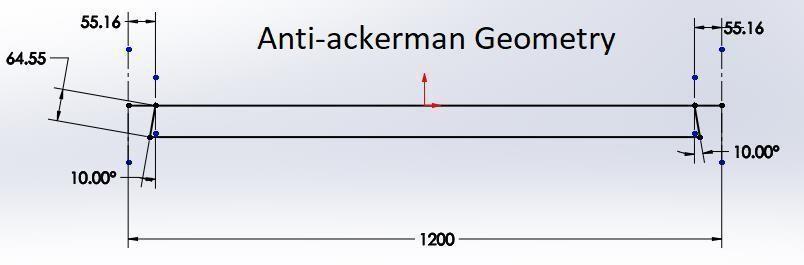
Intheeventthatpowersteeringisnotpermitted,wemust deviseamethodforthecartocompleteafullturnbyonly twistingthesteeringwheel halfway.Hencetherearesome waystoachievethat,likekeepingthesteeringratioaslessas possible. Also, there are 2 geometries in the steering mechanismwhichonecanincorporate-AckermanandAntiackermangeometry.Anti-ackermangeometrywasusedto improvethevehicle’sperformanceatsharpturns.
Thegoalwastooperatetheformulastudentelectriccarwith a dependable drivetrain system and a light weight wheel assembly system to improve the vehicle's dynamics performance.
Previously, automobiles' drivetrains were developed with theoutputofthecombustionpowertraininmind,butthis year we must design the drivetrain with the electric powertraininmind.Todoso,wemustconstructthegearbox to produce the appropriate torque. To reduce unsprung massinawheelassemblysystem,theweightofthewheel assembly must be reduced. To do this, we changed the substanceofthewheelassemblysystemandsiftedfromEN toAl.
Firstly we’ll discuss the design of the steering system completelyandthenshifttoWADandDrivetrain.
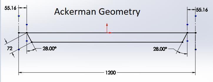
2.COMPARISON BETWEEN ACKERMAN AND ANTIACKERMAN GEOMETRY
Chart-1: AckermanGeometry
International Research Journal of Engineering and Technology (IRJET) e-ISSN: 2395-0056
Volume: 09 Issue: 09 | Sep 2022 www.irjet.net p-ISSN: 2395-0072
Rodendbearingsservetocompensateforangularimbalance acrosscontactsurfacesattheendsofcylinders,links,rods, andshafts.Theyaremadeupofasphericalinnerringanda cylindricalboreforshaftinstallation.Rodendbearingsare employed in applications where there is a minimal to moderateamountofaxisdistortion.
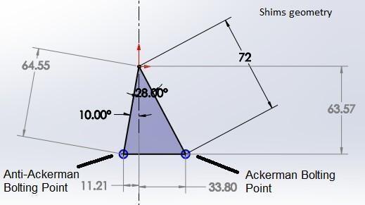
Chart-3:
Basically, this is the difference between the Ackerman geometry and anti-ackerman geometry. The difference is highlightedinthechartslistedabove.Further,thedifference intheboltingpointsinboththegeometriesisalsoshowed. Hence, one can easily decide that which type of is more suitable and beneficial for their vehicle or respective application.
Thistechniqueisstraightforwardanduser-friendly.Thisis themosteffectiveand,asaresult,extensivelyemployeddrive systembyautomakersworldwide.Itiswidelyacknowledged tobethefairestsolutiontoutilise.Apinionattheendofthe steering column meshes with the rack to form the mechanism.Atoneend,thepinionisattachedtothesteering column.Itengageswiththerack,whichslidestotheleftor rightbasedonthelocationofthepinion.
Forthetierod,wechoseAISI1018steelformanufacturingReasons to choose AISI 1018 material- According to our estimates,itcanwithstandallofthestressesinthesteering system without failing. The tyre rod buckles as a result of forces exerted on the tie rod. The tie rod can withstand a maximum buckling force of 3,099N without failing. Accordingly,AISI1018waschosen.
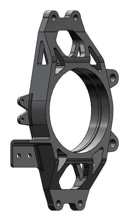
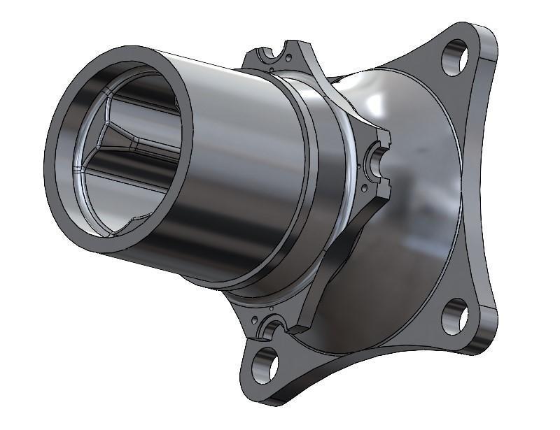
Afterselectingtoinstallarackandpinionsteeringsystem,we wentthroughseveraliterationsforthemajorcomponents, namely the rack and pinion. The rack and pinion housing, which houses the components, was the next priority. The dynamic forces were used to create the rack and pinion. Furthermore,therewereseveralcriticalelementstoconsider whenbuildingtherackandpinionhousing.Theprimarygoal is to keep the housing lightweight and compact enough to assure proper operation. AL6061 was utilised to make it lightweight.Wemustprovideslotsforthebearingsinorder forthegeartofunctionproperly.
Following iterations were performed to make it more compact.
Chart-4:Iteration1
Chart-5:Iteration2
International Research Journal of Engineering and Technology (IRJET) e-ISSN: 2395-0056
Volume: 09 Issue: 09 | Sep 2022 www.irjet.net p-ISSN: 2395-0072
The weights in the preceding iterations were 179.24 and 133.67, respectively.Finally,the iteration withless weight was chosen. We employed Linear Ball Bearings to achieve smoothmotionbetweentherackandpinionhousing,aswell astoreducefrictionbetweenthetwocomponents.Itserves as the connector between the rack and the tyres. This is utilisedtoconveythemotionoftheracktothetyre.Forthe tierod,wechoseAISI1018steelformanufacturing-Reasons tochooseAISI1018material-Accordingtoourestimates,it can withstand all of the stresses in the steering system without failing. The tyre rod buckles as a result of forces exertedonthetierod.Thetierodcanwithstandamaximum buckling force of 3,099N without failing. Accordingly, AISI1018waschosen.
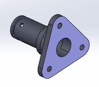
Webuiltarackconnectormadeofmildsteelforeasyexcess. This is used to join rack and tie rods using rod end bearings.The following goals were kept in mind when designingtheconnectorwhichwas toretaintheforcesacting onitgoing.SquareMembersonthecar'ssteeringsystemare usedtomountvariousgearhousingbrackets.Differentsizes andthicknessesofsquarememberswereconsidered,andthe bestonewaspickedappropriately.Mildsteelwasused. ItTo mounttheBevelGearHousingTomounttheRackandPinion Housing A steering column is employed. The rotational motionofabevelpinionistransferredtoarackpinion.For theconstructionofthecolumns,wechosemildsteel.Reasons for deciding on mild steel. Mild steel, according to our calculations, can be used to make columns since it can withstand all forces without failing.Mild steel is also more resistanttowear.
Weemployedbevelgeartoachievea45-degreeinnerangle for the tyres. We could accomplish the inner angle using universal joints, but to manoeuvre the vehicle, the driver would have to rotate the steering wheel at a considerably largeranglethanwiththebevelgeararrangement,whichis problematic because it is fully strapped. For connection, a bevelgearassemblyisemployedinsteadofauniversaljoint. Thesteeringratioisreducedwhenabevelgeararrangement isused.Bevelgearisintendedforagearratioof1.5.Wecan attainthebeststeeringratiobyemployingbevel gear.The steeringratiochangesafterinstallingbevelgears.Boththe bevelgearandthepinionaremadeofEN19material.Targets needed to achieve when designing the housing were as follows-SmoothfunctioningofBevelgearpair,Lightweight, tofitintheinternalcockpittemplate.
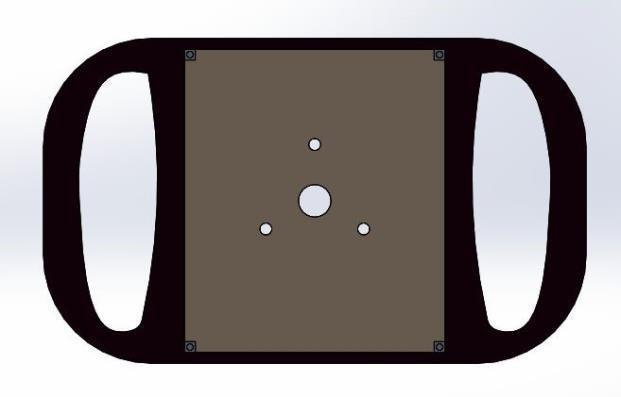
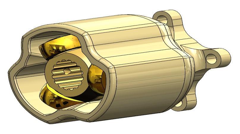
TheQuickReleaseHubconnectsandtransferstorquefrom thesteeringwheeltotheshaft.Thequickreleasebearingis used to quickly detach the steering wheel from the flange. Thequickreleasebearingisself-designedwithathree-hole layout.Itis2.67inchesthickandhasanM6boltthatconnects tothesteeringwheel.
Chart-6:QuickReleaseHub
Itspurposeistotransferforcesfromthedrivertotheentire system.Itisusedtosteerthecarandcontrolit.A3Dprinted wheel covered in two layers of carbon fibre. Self-designed and built near oval with outside parameter profile having somestraightsection.
Chart-7:Steeringwheel
Now,we’lllookatthedesignoftheWADanddrivetrains’key components.
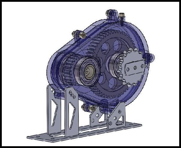
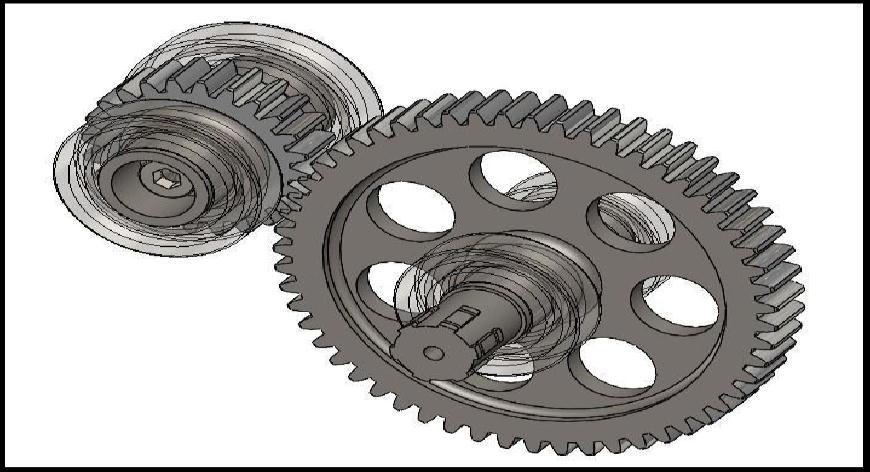
TheGearboxisdesignedtoamplifytheinitialmotortorque (i.e.65Nm)withareductionratioof2.29;inordertomeet ourrequirements,wehadtoemploy.Agearboxismadeupof several primary components, including: casing (head and base),drivinggear,drivengear,andbearings.Thedesignand selectionofSpurgearandgear-shafthasasignificantimpact onthegearbox'sreliability.Spurgearsarechosenfortheir great load carrying ability, smooth operation, and simple construction. To make the assembly more compact and
International Research Journal of Engineering and Technology (IRJET) e-ISSN: 2395-0056
reliable,thegearandshaftwerebuiltassinglecomponents; machinabilityisanothersignificantfactor.
The material utilised was EN36, and the production processesincludedmilling,gearshaping,andhobbing.
Whenwecomparedalltypesofdrives,wecompared
ChainName 428x no.oflinks 66 pitch 12.7mm rollerdiameter 7.77mm rollerwidth 5.207mm platethickness 1.47mm pindiameter 3.96mm plateheight 11.60mm
OurDepartment'smaingoalinselectingthedifferentialwas to find a reliable, light-weight differential with great performancecharacteristics.ByusingtheSpooldifferential, which is dependable, compact, and lightweight, with a straightforwarddesign.Becausethemotortorqueislower this year, the spool differential meets the torque requirementbytransferring100%oftorquetobothwheels.
WewerepreviouslyusingQuaifeATBgeartypeLSD,which transfers50%oftorquetoeachwheelinnormalconditions and improves vehicle performance in all conditions. The weightofLSDisgreaterthanthatofspool.
Seethefollowingfeaturesandwhywechosechaindrivefor ourtransmission.Forourtransmission,wechosethe428X chaindrive.
Becauseofthefollowingreasons,the428Xchainwaschosen overthe480OChain:
SimpleupkeepTheXringchainistwiceasdurableastheO ring chain. As it resists being squished, the X ring twists ratherthandeforms.
Sprocketlifeisextendedsinceitdoesnotbecomestiff.
To transfer torque from the differential assembly to the shafts, a constant velocity joint that allows for certain angulararticulationaswellasplungingmotionforstability waschosen. Constant-velocityjointswerechosen because they allow the drive shaft to transmit power through a
Volume: 09 Issue: 09 | Sep 2022 www.irjet.net p-ISSN: 2395-0072 © 2022, IRJET | Impact Factor value: 7.529 | ISO 9001:2008 Certified Journal | Page1047
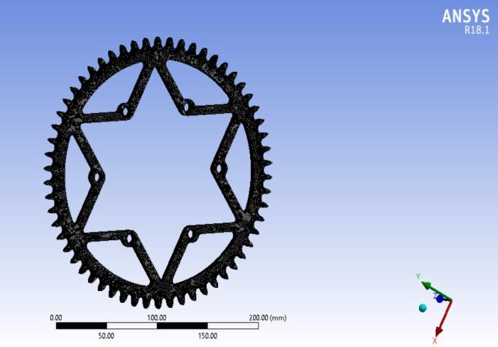
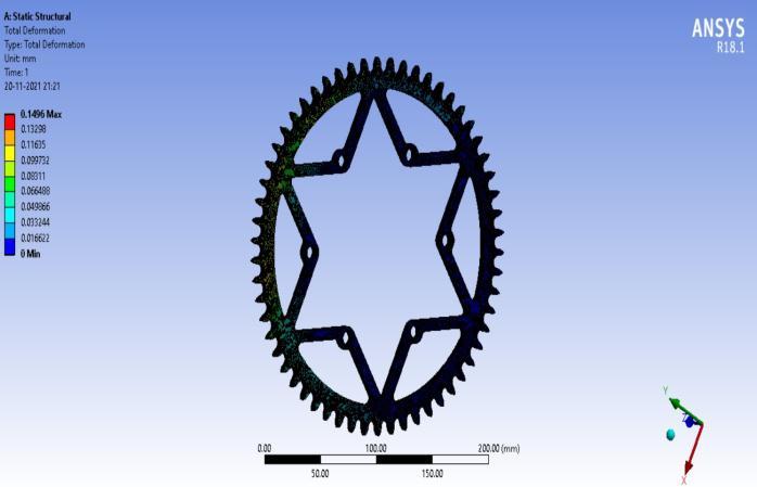
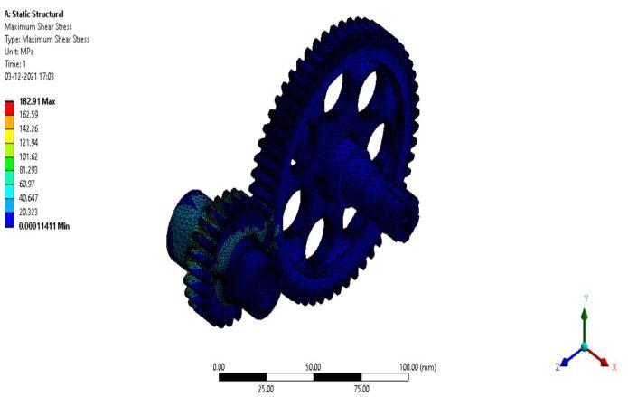
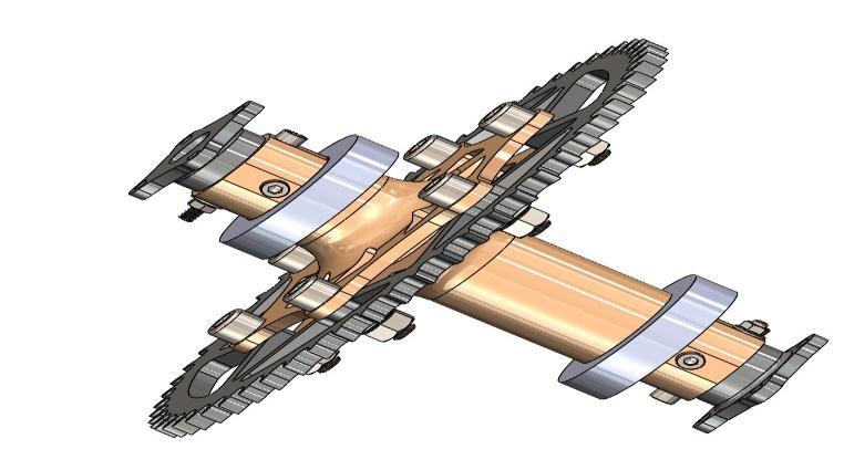 Chart-8:Gearbox
Chart-9:GearMeshing
Chart-8:Gearbox
Chart-9:GearMeshing
International Research Journal of Engineering and Technology (IRJET) e-ISSN: 2395-0056
Volume: 09 Issue: 09 | Sep 2022 www.irjet.net p-ISSN: 2395-0072
variable angle at a constant rotational speed while minimisingfrictionandplay.
AfterresearchingandcomparingvariousCVJointssuchas theR-Zeppajoint,Tractajoint,Balltypejoints,Inboardand Outboardjoints,theTripodCVJointwaschosenbecauseit allowed for required angular articulation and sufficient plungingwhilemaintainingconstantrotationalspeed.
SpiderBearingassemblyenablesplungingintripodtypeCV joint.Itismadeupofacentraldrivecomponentknownas theSpider.TheSpiderhasbeeninstalledontheshaft.Each spiderlegisequippedwiththreeAl7075Tripodbearings.
TripodJointAdvantages:Tripodscanplungeinandoutwith agreaterdistancethansuspensionmoves.Atypicaltripod jointhasaplungetravelofupto50mm.
Ithasamaximumangulararticulationofnearly23degrees, allowing for transmission at various angles. It is less expensiveandmuchmoreefficient.TheCVcupmaterialis changedfromstainlesssteeltoAluminium7075T-6,which canwithstandallforcesactingonit.AsingleCvCuphasbeen reducedinweightfrom960gmsto500gms.
sufficientlystronguprightthatcanwithstandtheforcesthat thenewfscarwillface.
Chart-11:Tripodjoint.
beenTheprimarygoalofouruprightdesignwastocreatean optimised structure that could house the location of ball joints,brakecalliper,steeringpoint,andtoepoint.
2.Theuprightshouldconnecttheupperandlowerballjoints. Itmustconnectthecomponents,suchasthecontrolarms, steering arms, springs, brake, and the axle at the rear. Because it is a critical component, it must withstand all forcesencounteredbythesuspension.
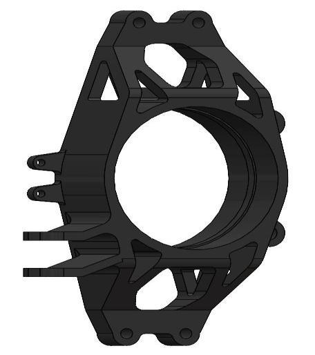
3.The upright must be strong enough to withstand those forces,whichmayoccurconcurrently,suchaswhenbraking intoacorner.Thegoalofthedesignistocreatealight,yet
Chart-13:Rearupright.
Material selection is a critical design parameter when creatingapartforFScompetition.
Theuprightshouldbestrongenoughtowithstanddynamic forces.
Cost,strength,andweightareimportantconsiderationsfor ourdesign.
It is intended to use aluminium 7075 for the uprights to reduce unsprung mass as much as possible because its strengthiscomparabletosteelanditiseasilymachined.Asa result of having less weight, the vehicle's dynamic performanceimproves.
For the material selection of the upright, parameters are taken.Cost,Ductility,andStrength.
International Research Journal of Engineering and Technology (IRJET) e-ISSN: 2395-0056
Volume: 09 Issue: 09 | Sep 2022 www.irjet.net p-ISSN: 2395-0072
Thehubshouldallowrotarymotiontothewheelandshould supportthemountingofthefollowingcomponents.
Brakedisc,Upright,theCastleNut,Bobbins.Thewheelhub mustbeabletowithstandtheforcesactingonit.Duringa race,fourmajorforcesactonthewheelhub:
Accelerationordecelerationforce,Turningacorner,Wheel movementorbump,Braketorqueversusaxletorque
Themaingoalistoreducetheweightofthehubbychanging materials such as Al Alloys grades and steel, while also increasingtheloadcarryingcapacityandstrengthofthehub.
HubsmadeofAl7075arepreferred.
Ithasgoodfatiguestrength,averagemachinability,andless corrosionresistancethanmanyotherAlalloys.However,its relatively high cost limits its use to applications where cheaperalloysareineffective.
WhencomparedtootherAlalloyssuchasAl-6061andAl7075, Al6061 does not have a high strength. The 7075 aluminiumalloy,ontheotherhand,iscommonlyuseddueto itshighstrength.
International Research Journal of Engineering and Technology (IRJET) e-ISSN: 2395-0056
Volume: 09 Issue: 09 | Sep 2022 www.irjet.net p-ISSN: 2395-0072
One of the most crucial systems is steering. Because we utiliseittosteerthewheels,itiscriticalthatthecarmakes aneffectiveturn.Ourmaingoalforthisseasonwastolower theweightofthesteeringsystemandcreateabetterdesign, which we successfully accomplished. In addition, we calculated the ideal values to facilitate pure cornering. Changingsettingsalsoresultedinlesssteeringeffort.
As seen in this report, component research, calculations, design, and analysis have been completed, and each component is the same to assemble on the drivetrain and wheelassembly.
Bycalculatingtherequired torque,wedesignthegearbox andchainsprocket,whichareusedtomagnifythetorque.By changing the material and designing optimizations, we reducetheweightofwheelassemblycomponentstoreduce the unsprung mass. As a result o, we are able to run our vehiclewithgoodtorqueandgooddynamicsperformance.
[1] “International Journal of Science and Research (IJSR).”
https://www.ijsr.net/?msclkid=be983237101d1b12175b53 bc64efa183(accessedNov.10,2021).
[2]“Selection,Design&AnalysisofTransmissionDrivesof FormulaStudentVehicleTransmissionSystem,”vol.08,no. 08,p.5,2021.
[3] “IRJET-V8I7604.pdf.” Accessed: Dec. 22, 2021. [Online]. Available: https://www.irjet.net/archives/V8/i7/IRJET-V8I7604.pdf
[4] Claude Rouille, “Differential behavior”, Optimum G lecturenotes.
[5] Milliken, William F., Milliken, Douglas L, “Race Car VehicleDynamics,”1985.
[6]CarrollSmith,”Tunetowin,”,1989.
[7]Kloppenburg,”Designofaracecardifferential”,Thesis, UniversityofToronto,(2008).
[8] “Gears- Gear Efficiency - Roy Mech.” https://roymech.org/Useful_Tables/Drive/Gear_Efficiency.h tml(accessedAug.12,2021).
PranavKhaladkar B.EMechanical Sayee Deshpande B.EMechanical


2022, IRJET | Impact Factor value: 7.529 | ISO 9001:2008 Certified Journal |