
International Research Journal of Engineering and Technology (IRJET) e-ISSN: 2395-0056
Volume: 12 Issue: 01 | Jan 2025 www.irjet.net p-ISSN: 2395-0072

International Research Journal of Engineering and Technology (IRJET) e-ISSN: 2395-0056
Volume: 12 Issue: 01 | Jan 2025 www.irjet.net p-ISSN: 2395-0072
Jaeho Chung1
1Yonam Institute of Technology, Professor, Dept. of Mechanical Engineering, Jinju, Republic of Korea
Abstract - The most widely used method of measuring the drag of an underwater object is to attach a sensor directly to the object. In addition, the classic method of measuring drag by attaching a rope or string to an underwater object is also used. However, these methods are known to be accurate in measuring the drag of a moving body at sea level in the form of a general ship, but they are not used in measuring the drag of a moving body in the deep sea where water pressure acts or an underwater moving body where a supercavitation phenomenon occurs. For that reason, this study conducted to develop a drag measurement method for underwater vehicles that is not subject to these limitations. In this study, we measure the power used by an underwater vehicle and measure the drag of the underwater vehicle from the power.
Key Words: Drag coefficient, Drag force, Power consumption method, Underwater vehicle, Supercavitating vehicle
1.INTRODUCTION
Several studies have been conducted to study the hydrodynamic forces, especially drag, acting on moving underwater bodies. These trends demonstrate the importance of developing drag prediction method. Additionally, these drag measurement studies were conductedinconjunctionwithdragreductionmethods[16]
Over the past two decades, various methods have been proposed to measure the drag coefficient of moving underwater objects. Yao et al. [7] and Jourdan et al. [8] proposedamethodofmeasuringthedragcoefficientofan underwater moving object in a specific Reynolds number range using a speed sensor and a pressure sensor in a water tunnel. Venukumar et al. [9] proposed a method to measure the drag coefficient of an object in a supersonic flow using an acceleration sensor, a speed sensor, and a pressure sensor. Sridhar and Katz [10] used the PIV system to find acceleration and velocity and devised a method to measure the drag coefficient of an object. In addition to these studies, various methodologies were proposed to measure the drag coefficient of underwater vehicles, but most used speed sensors and pressure sensors. Accordingly, this study presents a method to measure the drag coefficient of an underwater vehicle using power consumption. The power consumption method proposed in this study was used in Chung and
Cho’s study [4], which studied the underwater supercavitation phenomenon, and this paper presents a more specific methodology for the power consumption method.
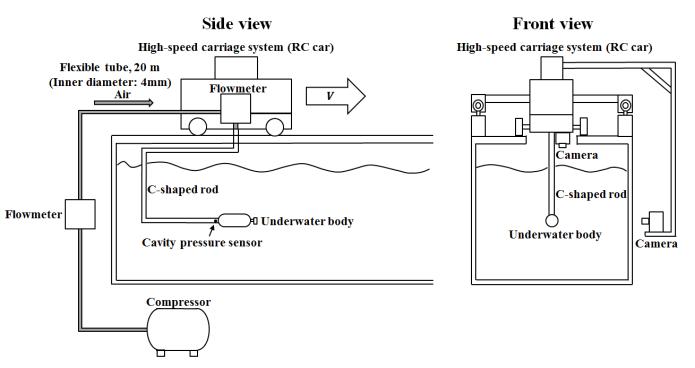
Fig -1:Experimental
To measure the drag coefficient of an underwater vehicle, an experiment was conducted using a tank designed as showninFigure1.Thetanksizeis19.2minlength,1min width,and1minheight,andthesidewallsofthetankare made of transparent glass for external observation. The towing system is a combination of a modified batterypoweredremote-controlled(RC)carandtwostraightrails laid along the entire length of the tank. The RC car runs alongtherailsata maximumspeedof10m/s,andtheRC car and the underwater body are rigidly attached to each other via a right-angled C-shaped connecting bar. Therefore, the underwater vehicle moves with the camera atthesamespeedastheRCcar.
Inthisstudy,thedragforce(FD)oftheunderwatervehicle is obtained from the power consumption of the battery consumedwhentheRCcarisrunning.AsshowninFigure 2, the power consumption was measured using a voltage sensorandacurrentsensor.
In the equation (1) above, P represents the power consumptionand V representsthespeedoftheunderwater vehicle.
International Research Journal of Engineering and Technology (IRJET) e-ISSN: 2395-0056
Volume: 12 Issue: 01 | Jan 2025 www.irjet.net p-ISSN: 2395-0072
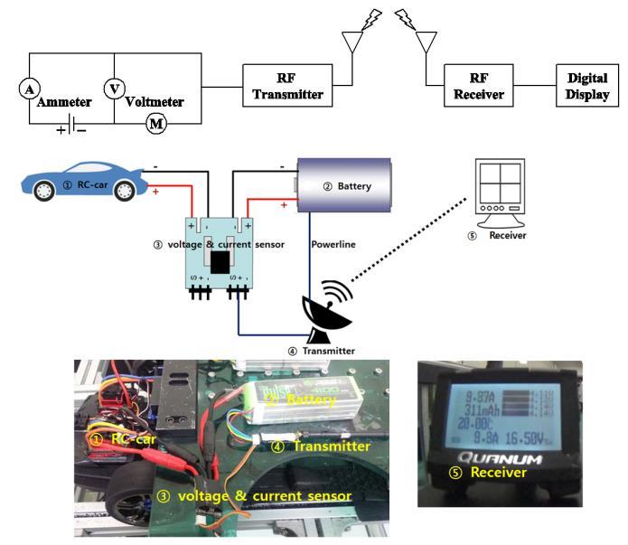
Fig -2:Measurementofpowerconsumption
3. Experimental results
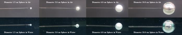
Fig -3:Movingspheresinwaterandair
Fig -4:Measurementofpowerconsumption (a)withasphere,(b)withoutasphere
In order to verify the drag measurement by the power consumption method proposed in this study, the drag coefficient was measured for a sphere-shaped moving body,suchasFigure3,movinginwaterandair.Asshown in Figure 4, the power consumption of the entire towing system required to move at a certain speed in water and airwasmeasured,andthenthepowerconsumptionofthe towing system excluding the sphere was measured. The drag of the sphere was then obtained as shown in Equation 3 below. In Equation 3, P1 is the power consumption of the entire towing system, and P2 is the power consumption of the towing system excluding the sphere.
Equation4showshowtoobtainthedragcoefficient(Cd)of a sphere using the drag obtained from Equation 3. In Equation 4, ρ represents the density of the fluid, and ds representsthediameterofthesphere.
Fig -5:Dragcoefficientaccordingto thediameter-basedReynoldsnumber
Figure5showsthedragcoefficientofthesphereobtained using Equations 3 and 4. In order to verify the drag coefficient measurement method by the power consumptionmethodproposedinthisstudy,theresultsof Goldsteian'sstudy [11] werecompared.Ascan beseen in Figure 5, the drag coefficients from the Reynolds number range of about 103 to 106 in this study were confirmed to be almost similar to the results of previous studies. After that, the drag coefficient measurement for an elliptical underwater vehicle was performed using the above method.
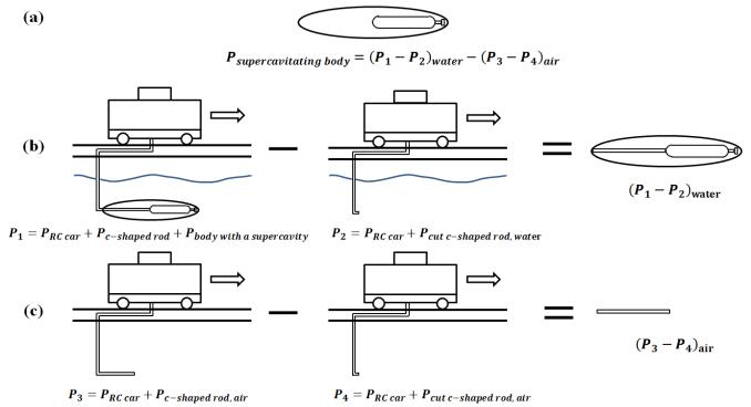
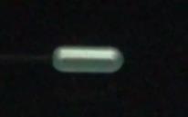
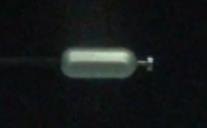
Fig -6:Methodformeasuringdragcoefficientofan ellipticalunderwatervehicleandanellipticalunderwater vehicleinasupercavitystate.(a)Underwatervehiclein
International Research Journal of Engineering and Technology (IRJET) e-ISSN: 2395-0056
Volume: 12 Issue: 01 | Jan 2025 www.irjet.net
supercavity,(b)supercavityvehicleandacutrodinsidethe supercavity,(c)acutrodinsidethesupercavity
We measured the drag coefficient of an underwater vehicle in a supercavity state using the drag coefficient measurement method described above, and conducted four different tests for this purpose. To measure the drag coefficientofanunderwatervehicleina supercavitystate as shown in Figure 6(a), we first conducted a test to measure the power consumption of the entire towing systemwithasupercavityformedasshowninFigure6(b), and then measured the power consumption of only the Ishapedbarintheairformedbythesupercavityasshown inFigure6(c).
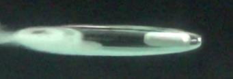
Table 1 shows the drag coefficients of a typical elliptical underwater vehicle, an underwater vehicle with a cavitator, and an underwater vehicle in a supercavity state. Case 2 in Table 1 is an underwater vehicle with a disk-shaped cavitator attached, and the drag coefficient was measured to be about 1.18. This result is almost similartothedragcoefficientofadisk-shapedunderwater vehicle [12]. And as in Case 3 of Table 1, the drag coefficientoftheunderwatervehicle with thesupercavity formed was measured to be approximately 0.11, and comparedto Case2 of Table1, whichhasthesameshape butnosupercavityformed,itwasconfirmedthatthedrag coefficient was reduced by approximately 76% when the supercavityphenomenonoccurred.
First, to calculate the power consumption of the underwater vehicle in the supercavity state and the Ishaped rod, as shown in Figure 6(b), the method of subtractingEquation6fromEquation5wasused.Then,to calculatethepowerconsumptionofonlytheI-shapedrod, as shown in Figure 6(c), the method of subtracting Equation8fromEquation7wasused.
This study conducted the experiment for drag coefficient measurement of underwater moving body. To examine howmuchdragisreducedornot,anewdragmeasurement method using power consumption is proposed and the dragforceofthesupercavitatingunderwatermovingbody is measured. Also, in this study, the drag coefficient of underwater moving body was measured using the power consumed by underwater body without any additional equipment.
Thus,thepowerconsumptioninthefinalstateasinFigure 6(a) was calculated using Equation 9, the drag was measuredusingEquation10,andthedragcoefficientwas measuredusingEquation11. Table
The drag coefficient measured by the drag measurement method proposed in this study was found to be almost identical to those of previous studies in the Reynolds number range from 103 to 106. However, other Reynolds numberrangescouldnotbemeasuredduetolimitationsin the experimental equipment. It was confirmed that the errorratewaslessthan5%intheReynoldsnumberrange from 103 to 104, and that the error rate in the Reynolds number range from 105 to 106, where the drag coefficient changes rapidly, was less than 2%, which is almost identical.
As a result of measuring the drag coefficient of an underwater vehicle in a supercavity state by applying the proposed drag measurement method, it was confirmed that the drag coefficient was reduced by approximately 90%inthecaseofanunderwatervehicleequippedwitha cavitator.
This work was supported by the 2024 Yanam institute of Technologygrant.
International Research Journal of Engineering and Technology (IRJET) e-ISSN: 2395-0056
Volume: 12 Issue: 01 | Jan 2025 www.irjet.net p-ISSN: 2395-0072
[1] E. L. Amromin, “Vehicles drag reduction with control of critical Reynolds number”, Journal of Fluids Engineering,135,10,2013,pp.101105.
[2] E. O. Akindoyo and H. A. Abdulbari, “Investigating the drag reduction performance of rigid polymer-carbon nanotubes complexes” Journal of Applied Fluid Mechanics,9,3,2016,pp.1041-1049.
[3] S.A.Jordan,“Understandingtowtankmeasurementof total drag for long thin circular cylinder”, Journal of FluidsEngineering,136,3.2014,pp.031205.
[4] J. Chung and Y. Cho, “Ventilated supercavitation aroundamovingbody ina stillfluid:observationand drag measurement”, Journal of Fluid Mechanics, 854, 2018,pp.367-419.
[5] G. Ghassabi and M. Kahrom, “Investigating flat plate drag reduction using Taguchi robust design”, Journal ofAppliedFluidMechanics,8,4,2015,pp.855-862.
[6] G. Q. Zhang, J. Schluter, X. Hu, “Parametric investigation of drag reduction for marine vessels using air filled dimpled surface”, Ships and Offshore Structures,13,3,2018,pp.244-255.
[7] Y. Yao, J. Luo, H. Liu, K. Zhu, “Water tunnel experimental investigation on drag reduction of coatingsurfacewall”ProcediaEngineering,126,2015, pp.247-253.
[8] G.Jourdan,L.Houas,O.Igra,J.L.Estivalezes,C.Devals, E. E. Meshkov, “Drag coefficient of sphere in a nonstationaryflow:newresults”ProceedingsoftheRoyal SocietyA,463,2007.
[9] B. Venukumar, G. Jagadeesh, K. P. J. Reddy, “Counterflow drag reduction by supersonic jet for a blunt body in hypersonic flow” Physics of Fluids, 18, 118104,2006.
[10] G. Sridhar and J. Katz, “Drag and lift forces on microscopic bubble entrained by a vortex”, Physics andFluids,7,1995,pp.389-399.
[11] S. Goldstein, Modern developments in fluid dynamics, OxfordUniversityPress,NewYork,1938.
[12] F. M. White, Fluid Mechanics (4th edition), McGrawHill,NewYork,1999.

Jaeho Chung, He received his Ph.D. from the Department of Mechanical Engineering at the KAIST and is currently a professor at the Dept. of Mechanical Engineering at YonamInstituteofTechnology.