International Research Journal of Engineering and Technology (IRJET) e-ISSN: 2395-0056

Volume: 09 Issue: 09 | Sep 2022 www.irjet.net p-ISSN: 2395-0072
International Research Journal of Engineering and Technology (IRJET) e-ISSN: 2395-0056
Volume: 09 Issue: 09 | Sep 2022 www.irjet.net p-ISSN: 2395-0072
Vivekananda T1 , Mahesh Kumar N2
1PG Student (M.Tech in VLSI Design & Embedded Systems), Department of Electronics and Communication Engineering, Dayananda Sagar College of Engineering, Bengaluru, Karnataka
2Associate Professor, Department of Electronics and Communication Engineering, Dayananda Sagar College of Engineering, Bengaluru, Karnataka ***
Abstract - Communicationprotocolplaysanimportantrole in organizing communication between the devices. These protocols have specific set of rules and agreed upon between the devices to achieve successful communication. UART and SPI are two widely used protocols in serial communication. ThispaperincludesthedesignoftheUARTandSPIfunctional module SV hardware description language. Functional verification ofthe UARTand SPIisperformedwiththe helpof the Universal Verification Methodology. The reusable UVM testbench architecture is designed to drive the randomized stimuli to the unit under test to check the functional correctness, by comparing the collected response to the intended response using the scoreboard mechanism. Reusability of the stimulus will reduce the overall execution time
Key Words: UART-Universal Asynchronous ReceiverTransmitter, SPI-Serial Peripheral Interface, UVMUniversal Verification Methodology, SV-SystemVerilog, Codecoverageanalysis
InVLSIchipdesignprocess,verificationofthedesignplaysa veryimportantrole.Thedesignmustbetestedfordifferent testcasesto verifyitsfunctionality.Ittakesa lot of effort, time for the verification of integrated circuits and its efficiency measure is a tedious job. The complexity of verification increases with the complexity of the device's design [1]. The verification of complex designs consumes approximately 60-70% of the product development life cycle, and cannot be achieved by the traditional directed testing method [2]. Verification of IC’s using Verilog/ SystemVerilog lacks the test bench’s reusability for environment and also consumes more time. Universal VerificationMethodologyisthestandardformofVerification [1]. The UVM has numerous class libraries which enable reuseoftheenvironmentacrosstheprojects.Inthispaper, wehaveusedatwocommunicationprotocoldesignstodo verificationusingtheUVM.OneisUARTandanotheroneis SPI. Communication protocols can be divided into two categories: Inter system protocols and Intra system protocols. Inter system protocol is implemented in communication between two distinct devices, such as a computer and a microcontroller kit through inter bus system.UARTistheoneoftheintersystemcommunication
protocol.UARTstandsforUniversalAsynchronousReceiverTransmitter.UARTisahardwarecommunicationprotocol that is primarily used for data transmission over a long distanceandbetweenthedeviceswithhighreliability.Itcan beusedinbothtransmissionandreceivingofadataserially inasynchronousway[1].UARTisanasynchronous,means communication between the devices without using clock signal. It has two pins, one is transmitter and another is receiver. Parallel data is converted into serial format by UART transmitter after receiving from system bus and transmits.Serialdataisconvertedbackintoparallelformat by UART receiver and send it to system bus. For transmission and receiving data between two UART modules,onlytwowiresarerequired.
Intra system protocol is implemented in communication betweentwodevicesontheprintedcircuitboardorSoC’s. SPIistheoneoftheintrasystemcommunicationprotocol. SPI stands for Serial Peripheral Interface. SPI is primarily usedfordatatransmissionoverashortdistancewithhigh speed and reliability. SPI is a synchronous, full-duplex interfacewithamasterslavearchitecture,whichusesclock forthecommunication.Therisingorfallingedgeoftheclock is used to synchronise the data from the master or slave. Datacanbesentorreceivedsimultaneously.TheSPIcomes in either 3-wire or 4-wire interface. The clock signal producedbythemasterservesasthesynchronizerfordata transmission.
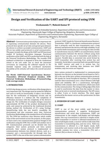
UART is one of the most widely used hardware communication protocol. It supports bi-directional, asynchronous and serial data transmission. UART can communicate in the simplex, half-duplex and full-duplex modes.Onewaytransmissionisallowedinsimplexmode. Eithertransmitterorreceiverisallowedtransmissionata timeinhalfduplexmode;areceiverwillbeinidlestateifthe transmitteristransmittingdata,andviceversa. Bothway transmissions is allowed in a full duplex mode; both transmitterandreceiverworkatthesametime[3].UART typically contains two wires: a transmitter (Tx) and a receiver(Rx)asshowninthefig-1.
International Research Journal of Engineering and Technology (IRJET) e-ISSN: 2395-0056
Volume: 09 Issue: 09 | Sep 2022 www.irjet.net p-ISSN: 2395-0072
themaster-slaveconfiguration.SPIsupportssinglemastersingle slave and single mater-multiple saves architectures. SPI supports bi-directional, synchronous and serial data transmission.Transmissiontakesplaceonsynchronousclock signalgeneratedbythemaster.SPIneedsjustfourlinesfor thecommunicationtohappenbetweenthemasterandthe slave[7].
ThetransmittingUARTconvertsparalleldataintoserialdata, once received from the data bus. The receiving UART translatesbacktoparalleldataafterreceivingserialdatabit by bit. No clock synchronization between transmitter (Tx) andreceiver(Rx),thismeanstheyhavetoagreebeforehand toaclockfrequency.Thisisdonebysettingthebaudratefor UART Tx and UART Rx. Transmission of data speed is measured as a baud rate, which is represented in bits per second (bps).UART can works in different baud rates like 1200, 2400, 4800, 9600, and 115200 bps. Tx and Rx must functionatsamebaudrateinthebothUARTs[1][3] Datais sentintheformofpackets.
FrameformatofaUARTisshowninthefig-2 Itconsistsof startbit,stopbitandparitybit.Thebeginningandfinishofa message are represented by the startand stop bits. At the receivingend,theparitybitactsasthecheckbit.Paritybitis optionalanddependsonrequirements.
Communication in UART is initiated by transmitter in the form of frame. Start, stop, and parity bits are added to constructadataframe.Thedataframeisthentransmitted seriallytoTxpin.Rxpinreadsthedataframeandremoves thestartandstopbit.Actuallylengthofthedatais5to8bits [4].
SPIisoneofthemostwidelyusedcommunicationprotocol. SPIstandsforSerialPeripheralInterface.SerialPeripheral Interfacesupportssynchronous,fullduplexcommunication andserialdatatransmissionwithhighspeedovertheshort distance.Shortdistancemeanscommunicationbetweenthe devices on the same board. SPI is mainly used for communication between the microcontrollers/microprocessorsandperipherals[6].SPIprotocolsrequiresclock signal for synchronization between the transmission and receptionduringthecommunication.SPIprotocolworksin
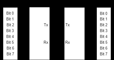
SPIsinglemaster-slavearchitectureisshowninthefig-3.SPI consists of the foursignals:serial clock (SCK), chipselect/ slaveselect(CS),masterinslaveout(MISO)andmasterout slavein(MOSI).Therisingorfallingedgesoftheclockare used to send and receive data from the master and slave, respectively.Thesignaldescriptionoftheserialperipheral interface
Master In Slave Out (MISO): UsingaMISOline,themaster chipreceivesdatafromtheslave.Transmitsdataseriallyone directionwithMSBbitsentfirst.TheMISOlinewillbeina highimpedancestateiftheslavechipisnotchosen.
Master Out Slave In (MOSI): UsingaMOSIline,themaster chiptransmitsdatatotheslavechip.MSBbitissentfirstand insingledirectionseriallyduringdatatransmission.
Serial Clock (SCK): Serialclockisusedtosynchronisedata betweenthemaster&slaveandthrMOSI&MISOsignalline. Abyteofdatacanbeexchangedbetweenaslaveandmaster deviceineightclockcycles.SCKisgeneratedbythemaster deviceandisusedastheslavedevice'sinputclock.
Chip/Slave Select (CS): Theslavechipisselectedusingthe chipselectlineofslave.Itshouldstayactivelowduringdata transfer[6-8].
AfterCommunicationintheSPIisinitiatedbythemasterand configurestheclock.Masterusestheclockconfiguretoset the frequency which must be less than or equal to slave
International Research Journal of Engineering and Technology (IRJET) e-ISSN: 2395-0056
Volume: 09 Issue: 09 | Sep 2022 www.irjet.net p-ISSN: 2395-0072
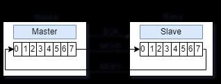
device’s maximum frequency. The master will select the particularslavedeviceforcommunicationthroughtheslave’s CSlinetolowstate.MOSIlineisusedtoshiftthedatafrom shift register to slave and slave shifts the data into shift register. MISO line is used to shift the data from slave to masterinthesamefashionasMOSIasshowninthefig-4[6].
Verificationisaprocessofdeterminingwhetherthedesigned modulemeetsthespecificrequirementsinthedesignofIC’s. UVM is a standard methodology for verifyingintegrated circuitdesigns.AbbreviationofUVMisUniversalVerification Methodology. UVM is mainly derived from the open verificationmethodology(OVM).TheOVMwascreatedasa resultofajointeffortbetweenCadenceDesignSystemsand Mentor Graphics to integrate the ideas of Universal Reuse Methodology(URM)andAdvancedVerificationMethodology (AVM).UVMusesSystemVerilogforverification.Additionally, Synopsys joined and combined the Reference Verification Methodology (RVM) and OVM methodologies to create Universal Verification Methodology (UVM), which was approved by the Accellera committee to become the new standard to be used for the functional verification of integrated circuit designs in 2009 [2] Based on the requirementoftheproject,someofthepointsconsideredin the UVM are code re-usability, build the verification environment, random stimulus generation and verify the designundertestusingtheenvironment. Fig-5showsthe typicalUVMtestbencharchitecture.
ThemajorthreecategoriesofclassesatUVMareasfollows.
uvm_object: BaseclassintheUVMforuvmdataandother classes for operational method. uvm_component and uvm_transactionareinheritedfromit.
uvm_transaction: Serves as the root base class for uvm componentsandutilizedinthegenerationofstimuli.
uvm component: are essentially static and remain throughout the simulation. Top, Agent, Sequence Item, Sequence, Test, Environment, Driver, Sequencer, Monitor, Scoreboardaretheuvm_components.
Thevariousphasesofalltheuvmcomponentsare
Build phase: Basedonconfigurationandfactorysettings,it createsandconfigurescomponenthierarchies.
Connect phase: Establishesconnectionbetweentheportsof variousuvmcomponentswithoneanother.
Run phase: Implementasataskforuvmcomponentswhich ispresenceduringtheentirerun-time.
Extract phase: Acquires data from scoreboards and functionalcoveragemonitorsandprocessit.
Check phase: CheckswhetherDUTisbehavingproperlyand identifyerrorsduringexecutionoftestbench.
Report phase: Displays simulation results and also saves resultstoafile
Final phase: Terminationofthesimulation.
Fig -5: UVMtestbencharchitecture
UVMtestbencharchitecturehasthefollowingcomponents
Testbench: Instantiates the both unit under test and test class.Andalsoestablishesconnectionbetweenthem.
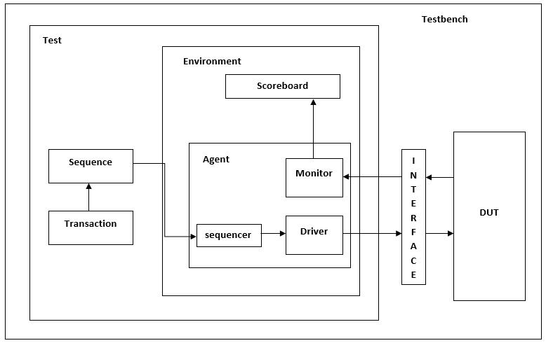
Test: Configuresthetestbench,constructionofahigherlevel lowerinthehierarchywillserveastheinitialtestbenchparts developmentmeasureandinstantiatesthesequencetobegin thestimulus.
Environment: Verificationcomponentslikescoreboardand agentaregroupedtogetherforreusability.
Agent: Incorporates monitor, driver and sequencer as a signalentitythroughtheTLMinterface.
Sequencer: Thetaskofthesequenceristoguidetransactions (also known as sequence items) that are generated in sequencetothedriverorviceversa.
Driver: Retrievesdatafromsequencerandsendsthesameto DUTandreferencemodelthroughinterface.
Monitor: Samplestheunitbeingtestedandreferencemodel, recordsthedatapresentintransactions,andthencompares it.
Scoreboard: Consists of checkers to verify the design functionality.
Sequence: Generating and receiving the data items in sequencetoandfromthedriverisdone.
International Research Journal of Engineering and Technology (IRJET) e-ISSN: 2395-0056
Volume: 09 Issue: 09 | Sep 2022 www.irjet.net p-ISSN: 2395-0072
Sequence item: Actsasaplaceholderfortheprocedurethat themonitorwillcheckonDUTsignals.
Code coverage analysis gives feedback to the report file regardingtheexecutionofstatements,branches,conditions, andexpressionsinthesourcecodeandmeasurestheamount of logic that is toggled during execution. Code coverage mainly includes statement coverage, condition coverage, branch coverage, expression coverage, focused expression coverageandtoggledcoverage.
Functional modules for the above discussed protocols are designedusingSystemVerilogHDL,compiledandsimulated using QuestaSim. UVM verification and Code coverage analysisareperformedonthedesignedfunctionalmodules usingQuestaSim10.7cincludewithUVM1.2.
Fig -6: SimulatedwaveformofUART
Abovefig-6showsthesimulatedwaveformoftheUARTdata transactionbetweentransmitterandreceiver.Transmission ofthedatahappensonthepositiveedgeoftheclockcycle.
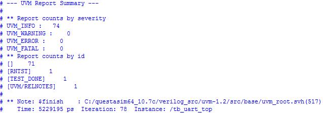
Fig -8: UVMreportsummaryofUART
UVMreportsummaryinfig-8givesthedetailsofWARNING, ERROR,FATAL,numberoftestcase,iterationandtimetaken duringtheUVMverification.
Fig -9: SimulatedWaveformofSPI
Above fig - 9 shows the simulated waveform of the serial peripheralinterfacedataexchangebetweenthemasterand slaveduringMISOandMOSImodeofoperation.
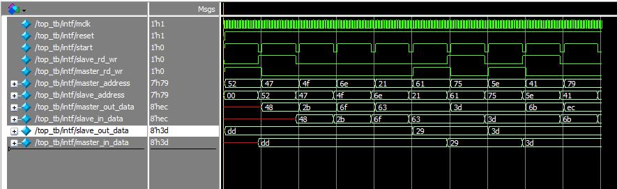
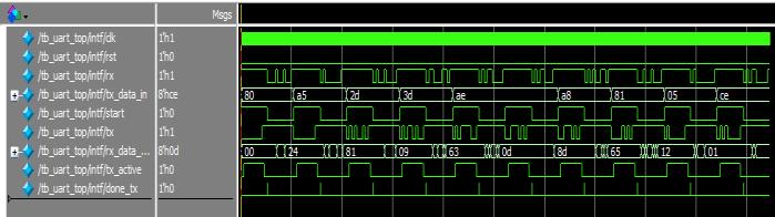
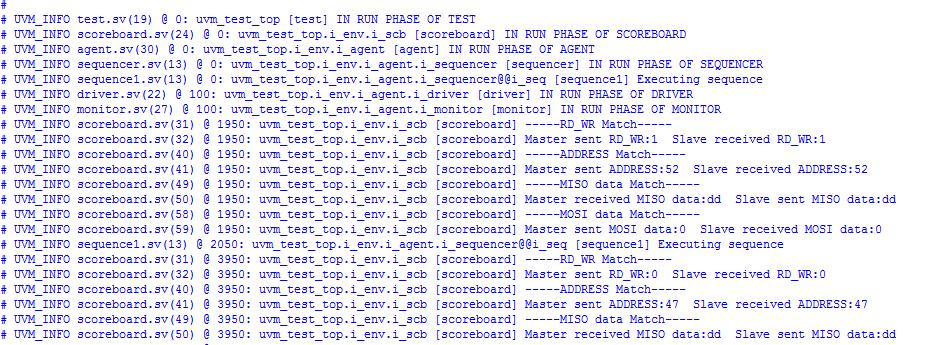
Fig -10: UVMreportofSPI’sdatatransactionbetween masterandslave
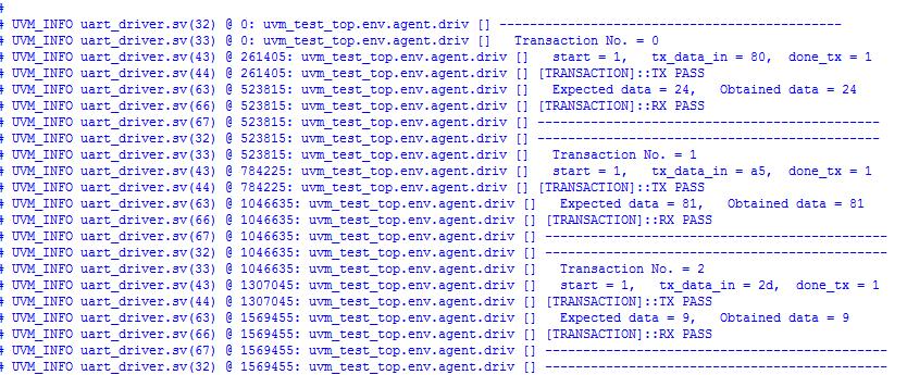
Fig -7: UVMreportofUARTdatatransactionbetweentx andrx
UVM report in the fig -7 gives the transaction details like transaction numbers, transaction of the data between the transmitterandreceiverpassedorfailed.Here,wehaveused the10transactions.Oncethedataistransmittedsuccessfully, willgetthemessage[TRANSACTION]::TXPASS.Afterthedata isreceivedsuccessfully,expecteddataandobtaineddatais comparedinthescoreboardoftheUVM.Iftheboththedata are same, will get the message [TRANSACTION]::RX PASS. Dataischosenrandomlyusingtheconceptofrandomization.
UVMreportinthefig-10givesthesuccessfuldatatransfer betweenmasterandslaveandvice-versa.Transactiondetails like RD_WR Match, address Match, MISO data Match and MOSI data Matchare shownon successful data exchanged betweenthemasterandslave
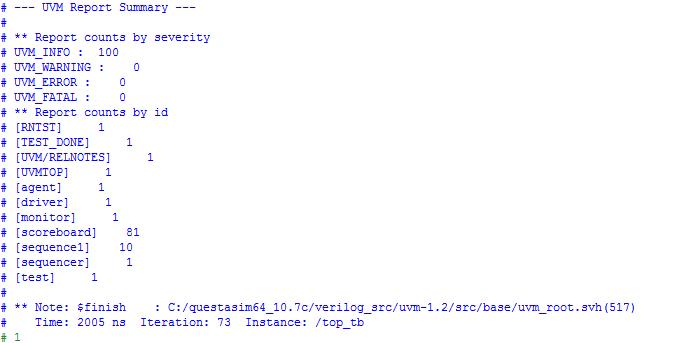
Fig -11: UVMreportsummaryofSPI
International Research Journal of Engineering and Technology (IRJET) e-ISSN: 2395-0056
Volume: 09 Issue: 09 | Sep 2022 www.irjet.net p-ISSN: 2395-0072
UVMreportsummaryinfig-11givesthedetailsofWARNING, ERROR,FATAL,numberoftestcase,iterationandtimetaken duringtheUVMverification.
Fig -12: CodecoveragereportofUART
Fig –15:CodecoverageofSPImaster
Fig -15 shows the code coverage details of SPI master functionalmodule.
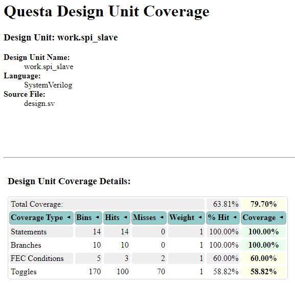
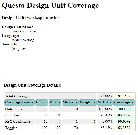

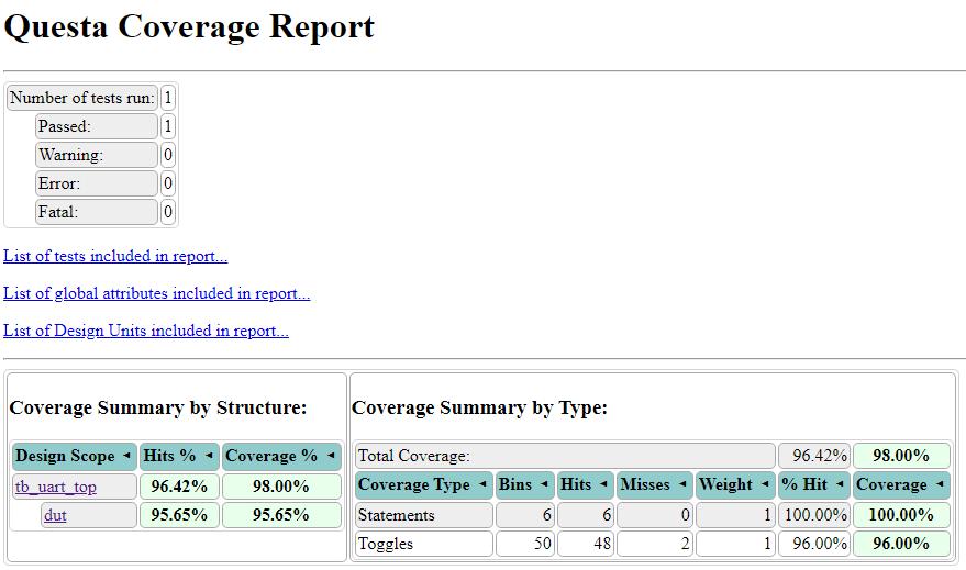
Fig -13: CodecoveragereportofSPI
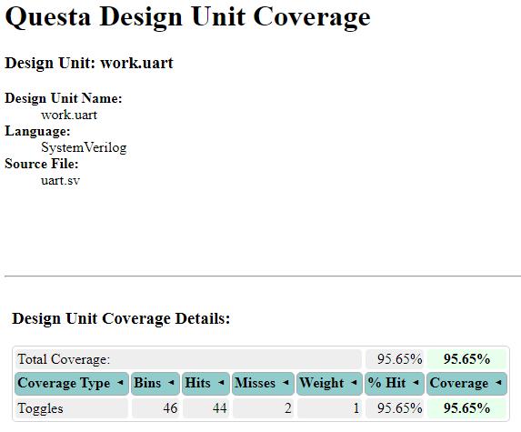
Fig-12andfig-13showsthecodecoveragereportofUART andSPIfunctionalmodules.
Fig -16: CodecoverageofSPISlave
Fig-16showsthecodecoveragedetailsofSPIslavefunctinal module.
Fig-14:CodecoveragedetailsofUARTfunctionalmodule
2022, IRJET | Impact Factor value: 7.529 | ISO 9001:2008 Certified Journal
International Research Journal of Engineering and Technology (IRJET) e-ISSN: 2395-0056
[1] PriyankaB.,GokulM.R.,NigithaA.,&Poomica.,J.(2021). “Design of UART Using Verilog And Verifying Using UVM”.20217thInternationalConferenceonAdvanced Computing and Communication Systems (ICACCS), 1, 1270-1273.
[2] B. Vineeth;B. Bala Tripura Sundari, "UVM Based TestbenchArchitectureforCoverageDrivenFunctional Verification of SPI Protocol", 2018 International ConferenceonAdvancesinComputing,Communications andInformatics(ICACCI),2018sep19
[3] AshokKumarGupta,AshishRaman,NaveenKumar,and RaviRanjan“DesignandImplementationofHigh-Speed Universal Asynchronous Receiver and Transmitter (UART)”20207thInternationalConferenceonSignal Processing and Integrated Networks (SPIN) IEEE 20 April2020
Fig -17: CodecoverageofUARTtestbench
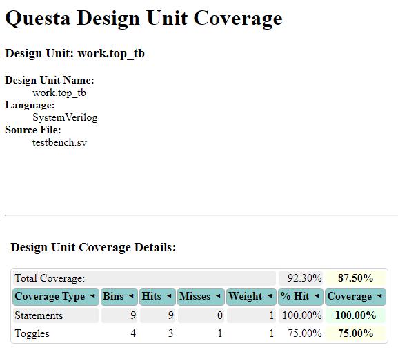
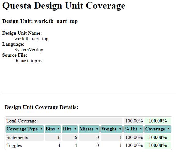
Fig-17showsthecodecoveragedetailsofUARTtestbench
[4] KashyapB,RaviV.“UniversalVerificationMethodology Based Verification of UART Protocol” InJournal of Physics:ConferenceSeries2020Dec1(Vol.1716,No.1, p.012040).IOPPublishing.
[5] PallaviPolsani,V.PriyankaB.,Y.PadmaSai,“Designand VerificationofSerialPeripheralInterface(SPI)Protocol” International Journal of Recent Technology and Engineering(IJRTE)ISSN:2277-3878(Online),Volume8Issue-6,March2020
[6] Dr.Punith Kumar M B, Sreekantesha H N, “Design and VerificationofSPICoreUsingUVM”JournalofEmerging Technologies and Innovative Research (JETIR) JETIR May2019,Volume6,Issue5
[7] Kulkarni A, Sakthivel SM. “UVM methodology based functional Verification of SPI Protocol” In Journal of Physics:ConferenceSeries2020Dec1(Vol.1716,No.1, p.012035).IOPPublishing
Fig -18: CodecoverageofSPItestbench
Fig-18showsthecodecoveragedetailsoftheSPItestbench
ThispapercontainsthebriefdiscussionoftheUARTandSPI protocols. The work includes the design of the functional modules of UART and SPI using SystemVerilog HDL. UVM testbench environment is built for the designed modules. Functional modules are simulated using QuestaSim 10.7c. UVM verification and code coverage analysis of designed modules are performed using the QuestaSim 10.7c precompiledwithUVM1.2.
[8] NiW,WangX.“Functionalcoverage-drivenUVM-based UART IP verification” In2015 IEEE 11th International Conference on ASIC (ASICON) 2015 Nov 3 (pp. 1-4). IEEE.
[9] YaminiR,&RamyaMV.(2020).“DesignandVerification ofUARTusingSystemVerilog”InternationalJournalof Engineering and Advanced Technology (IJEAT), 9(5), 1208–1211
[10] Roopesh, D Siddesha K, Kavitha Narayan B M “RTL DESIGN AND VERIFICATION OF SPI MASTER-SLAVE USING UVM” International Journal of Advanced ResearchinElectronicsandCommunicationEngineering Volume4,Issue8,August2015.
Volume: 09 Issue: 09 | Sep 2022 www.irjet.net p-ISSN: 2395-0072 © 2022, IRJET | Impact Factor value: 7.529 | ISO 9001:2008 Certified Journal | Page101
International Research Journal of Engineering and Technology (IRJET) e-ISSN: 2395-0056
Volume: 09 Issue: 09 | Sep 2022 www.irjet.net p-ISSN: 2395-0072
[11] Y. Fang and X. Chen, "Design and Simulation of UART Serial Communication Module Based on VHDL",2011 3rdInternationalWorkshoponIntelligentSystemsand Applications,pp.1-4,2011.
2022, IRJET | Impact Factor value: 7.529 | ISO 9001:2008 Certified Journal