International Research Journal of Engineering and Technology (IRJET) e-ISSN: 2395-0056

Volume: 09 Issue: 09 | Sep 2022 www.irjet.net p-ISSN: 2395-0072

International Research Journal of Engineering and Technology (IRJET) e-ISSN: 2395-0056
Volume: 09 Issue: 09 | Sep 2022 www.irjet.net p-ISSN: 2395-0072
R Rakshith1 , H Suresh2 , Nachiketh G V3 , Syed Khaleel Ahmed4, T J Shreyas5
1R Rakshith, Student, EEE Dept., BIT Bangalore, India
2H Suresh, Assistant Professor, EEE Dept., BIT Bangalore, India 3 Nachiketh G V, Student, EEE Dept., BIT Bangalore, India
4 Syed Khaleel Ahmed, Student, EEE Dept., BIT Bangalore, India
5T J Shreyas, Student, EEE Dept., BIT Bangalore, India ***
Abstract - A DC-DC converter is one of the simplest and widely used converters in controlled power applications like cell phones, laptops, communication systems and many more electronic devices. DC-DCconvertersaredeviceswhichconvert one voltage level to other voltage level that may be higher in magnitude or lower in magnitude. Accordingly they are classified as boost and buck converters.Weareworkingonthe latter i.e., buck converter. They are used everywhere because of their high efficiency and single stage conversion. These converters are nothing but, high frequency switching devices operating on PWM principle. Almostalloftheswitching-mode power conversion systems generate conducted electromagnetic interference (EMI) noise. In this paper, we propose a design method of the EMI filter with DC-DC power converter and implement them to reduce the EMI noise generated, and thereby improve the overall efficiency of the power converter.
Key Words: DC power supplies, EMI Filter, EMI noise, Switch-Mode Power Supplies, Buck converter.
DC-DC converters are electronic devices that are used to changeDCelectricalpowerefficientlyfromonevoltagelevel toanother.Thecontrolofvoltageisdonebycontrollingthe duty ratio of the switch. Switches used are MOSFETS, transistors,GTO’s,IGBT’sdependinguponthecircuitorthe powertransfercapability.Thecontrolofoutputvoltagetoa constant magnitude is achieved by the help of a feedback. The use of one or more switches for the purpose of powerconversioncanberegardedasaSwitch-ModePower Supplies (SMPS). Using a buck converteroffers amuch cheaper solution tosupplying large systems comprised of smallercomponents.
WewanttochangetheDCenergyfromonevoltagelevelto another,whilewastingaslittleaspossibleintheprocess.In other words, we want to perform theconversion with the highest possible efficiency. DC-DC Converters are needed becauseunlikeAC,DCcan’tsimplybesteppedupordown usingatransformer.InmanywaysaDC-DCconverteristhe DC equivalent of a transformer. DC to DC conversion of electronicmanufacturedcomponentsisalwaysindemandas
itsavesmoneyandmanydesignconstraintsbyallowinglow ratedcomponentstobeusedinlargersystems.
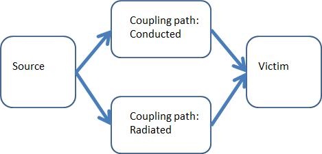
Electromagneticinterference(EMI)isharmfultosensitive electronicdevicesandisthusunwantedinelectricalcircuits. [1]EMI phenomenon requires three basic elements to be presentandtheyarethe“source”,the“couplingpath”and the“victim”,asillustratedinFigure1.
In an electronic device, efficiencies are valued. A power converter is used to control the flow of electrical energy basedonthedemandbytherequirementofthedevice.This allowsthepowerconvertertodeliverpowertoaloadwith maximum efficiency. Power converter also serves the purpose of converting unregulated AC or DC input power intoregulatedDCoutputpowerthatissuitableforthedevice to operate. For examples, computers, telecommunications systems and motor drives require regulated DC power supplies.However,powerconvertersarealsoamajorsource ofEMI.Inmostpowerconverters,highfrequencyswitching techniquesareutilised.Highfrequencyswitchingtechniques caneffectivelyreducethesizeofthepowerconverters,and also boost the efficiency of the power converter. In high frequencyswitchingtechniques,atransistorisswitchedon andoffrapidly.
Justinafractionofmicrosecond,thepowertransistorswitch chops voltage of a few hundred volts. When the power transistor is being switched on and off rapidly, while generating the desired frequency, harmonics of that frequencyisbeingproducedatthesametime.Thesehigher harmonicsproducedbytherapidswitchingactsasnoiseto
International Research Journal of Engineering and Technology (IRJET) e-ISSN: 2395-0056
Volume: 09 Issue: 09 | Sep 2022 www.irjet.net p-ISSN: 2395-0072
otherdevicesinthesamepowergrid.TheseconductedEMI at a much higher frequency as compared to frequencies adoptedbythepowertransistors,uptoseveraltensofMHz. ThemainsourcesofEMIindc-dcconvertersareduetodi⁄dt and dv⁄dt during a switching period. The conducted emissions are the major issue in most of the power electronicconvertersanditiscausedby
Strayinductanceofcurrentloopscausing highdi⁄dtcan create over voltages in high power dc-dc converters.
Straycapacitivecouplingbetweenwindingsandaframe resultinghighdv⁄dtcancreateleakagecurrentinmagnetic elementsandelectricmotors.
AC/DCmotors.
Switch-modepowersupplies(SMPS),duetohighswitching frequencyandreverserecoverycharacteristicsofdiode.
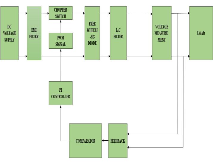
The above figure shows the block diagram of the buck converter.TheDCpowersupplyisconnectedtotheEMIfilter whichreducestheEMInoise,whichisinturnconnectedto thedrainoftheMOSFETswitch.TheMOSFETswitchisused asitoperatesforhigherfrequency(250KHz).Theschotkey diodeisusedasafreewheelingdiode.Sincethecurrentinthe inductorcannotchangesuddenly,apathmustexistforthe inductorcurrentwhentheswitchisoff.Thispathisprovided bythefreewheelingdiode.Thepurposeofthisdiodeisnotto rectify,buttodirectcurrentflowinthecircuitandtoensure that there isalways a path for the current to flowinto the inductor.Itisalsonecessarythatthisdiodeshouldbeableto turnoffrelativelyfast.Thusthediodeenablestheconverter toconvertstoredenergyintheinductortotheload.Thisisa reasonwhywehavehigherefficiencyinaDC-DCconverteras comparedtoalinearregulator.Whentheswitchcloses,the current rises linearly. When the switch opens, the freewheelingdiodecausesalineardecreaseincurrent.
Inductorandcapacitorsareusedtostoretheenergy.The capacitorisusedatinputandoutputsideinordertoreduce the ripple. Capacitor provides the filtering action by providinga pathfor the harmoniccurrentsaway from the load.Outputcapacitanceisrequiredtominimisethevoltage overshootandripple present at the outputofa step down converter.Thecapacitorislargeenoughsothatitsvoltage does not have any noticeable change during the time the switch is off. Large overshoots are caused by insufficient output capacitance, and large voltage ripple is caused by insufficient capacitance as well as high equivalent–series resistance in the outputcapacitor. The feedback is usedin ordertogettheconstantoutputvoltage(5V).Voltagesensor is used tomeasure the voltage valueat any given timeinterval.
To effectively reduce EMI in a circuit, the coupling path connecting the victim to the source must be made as inefficient as possible. As aforementioned, EMI is at much higher frequencies as compared to normal signals. Hence, EMIcanbesuppressedbyselectivelyblockingorshunting unwantedhigherfrequencies.Thus,thedutyofanEMIfilter istomakeelectricalsignalsofunwantedfrequencyunableto passthroughit.
An EMI filter is inserted before the power converter to prevent EMI generated by the device from entering the power grid. The filter also prevents EMI present in the power grid to enter the device and interfere with its performance.
ApassiveEMIfilterhastwomaincomponents,thecapacitor and the inductor. Both components attenuate the noise signals. A shunt capacitor is able to bypass the high frequencynoiseandaseriesinductorisabletoblockhigh frequency noise from passing through. Hence, these two componentsarecommonlyusedtoformanEMIfilter.The goal of this project is to test the designed EMI filters and determineiftheyarecapableofnoisesuppression.
Mode 1: The first state corresponds to the case when the switchisON.Inthisstate,thecurrentthroughtheinductor rises,andtheenergystoredinitincreases,duringthisstate theinductoracquiresenergy.
Vi=Lo*(diL/dt)+Vo=Lo*(ΔI/DT)+Vo
Whentheswitchisclosed,thediodeisintheOFFstate.
Mode 2: ThesecondstateiswhentheswitchisOFFandthe diodeisON.Inthisstate,theinductorcurrentfree-wheels throughthediodeandtheinductorsuppliesenergytotheRC networkattheoutput.Theenergyintheinductorfallsinthis state.
International Research Journal of Engineering and Technology (IRJET) e-ISSN: 2395-0056
Volume: 09 Issue: 09 | Sep 2022 www.irjet.net p-ISSN: 2395-0072
0=Vo+Lo*(diL/dt)=Vo-Lo*(ΔI/(1-D)T)
Whentheswitchisopen,theinductordischargesitsenergy.
Whenallofitsenergyhasdischarged,thecurrentfallstozero andtendstoreverse,butthediodeblocksconductioninthe reversedirection.Inthethirdstateboththediodeandthe switch are OFF, in this state the capacitor discharges its energyandtheinductorisatrestwithnoenergystoredinit. There cannot be a net change in flux in the inductor or it would saturate over a number of cycles. The increase in current while the switch is on must exactly equal the decreaseincurrentwhiletheswitchisopen.
((Vi-Vo)/Lo)*DT=(Vo/Lo)*((1-D)*T)
D=VO/Vi.
The conceptual model of the buck converter is best understood in terms of the relation between current and voltageoftheinductor.Beginningwiththeswitchopen(in the"off'position),thecurrentinthecircuitis0.Whenthe switchisfirstclosed,thecurrentwillbegintoincrease,and the inductor will produce an opposing voltage across its terminalsinresponsetothechangingcurrent.Thisvoltage drop counteracts the voltage of the source and therefore reducesthenet-voltageacrosstheload.
Overtime,therateofchangeofcurrentdecreases,and the voltage across the inductor also then decreases, increasing the voltage at the load. During this time, the inductorisstoringenergyintheformofamagneticfield.If theswitchisopenedwhilethecurrentisstillchanging,then therewillalwaysbeavoltagedropacrosstheinductor,sothe net voltage at the load will always be less than the input voltagesource.Whentheswitchisopenedagain,thevoltage sourcewillberemovedfromthecircuit,andthecurrentwill decrease. The changing current will produce a change in voltageacrosstheinductor,nowaidingthesourcevoltage. Thestoredenergyintheinductor'smagneticfieldsupports currentflowthroughtheload.Duringthistime,theinductor isdischargingitsstoredenergyintotherestofthecircuit.If the switch is closed again before the inductor fully discharges,thevoltageattheloadwillalwaysbegreaterthan zero.[6-8]
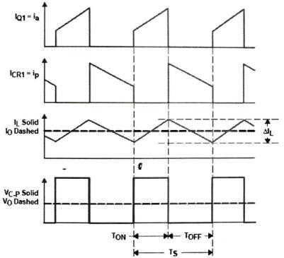
Fig-4:CircuitDiagram
Switchingfrequency,fsw=50KHz
Inputvoltage,Vin=25V Outputvoltage,Vout=5V Powerrating,P=2W Dutyratio,D=Vout/Vin =5/25=0.2 T=1/fsw =1/50KHz=0.2µs D=Iin/Iout P=2W,Vo=5V
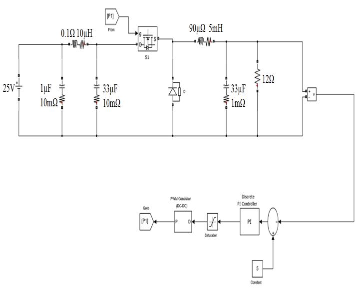
Therefore,Io=P/Vo =2/5=0.4A=400mA SubstitutingIo wegetIin Iin =D*Io =0.2*0.4=0.0834A~0.1A
Ifweconsiderthepeakcurrentas15%abovetheload currentIo Then, I=0.15*0.4=0.06A
CALCULATIONOFINDUCTANCE:
ΔT=ΔIL*L*Vi/(Vo(Vi/Vo))
L=5mH
International Research Journal of Engineering and Technology (IRJET) e-ISSN: 2395-0056
Volume: 09 Issue: 09 | Sep 2022 www.irjet.net p-ISSN: 2395-0072
T=D/fSW =0.2/50K =4µs
Letripplevoltagebe100mV Iripple=1/2*Iload =1/2*0.4 =0.2A
Outputcapacitance,Cout=Vo(Vin-Vo)/8*L*Vin*f2*changein Vo Cout =33µF
PICONTROLLER,Kp=5,Ki=500.
The EMI filter is designed by using chain parameters also known as ABCD parameters and stability analysis , these filtersaredesignedtoprovideinsertionloss (IL),butthey also affect converter’s dynamics and this should be consideredduringthedesignprocess[3]
The choice of the Emi filter configuration- T, LC or π dependsonthesourceand loadimpedances. If dcvoltage source is almost ideal, then there would be no difference betweenLCandπ-filter,inotherwords,π-filterwillperform asanLC-filterifthedclineimpedanceisnegligible.Inreal operation,thisisunlikelytooccurduetocablingparasitic inductance will make it inductive therefore a π- filter will performbetter.
• DCtoDCconversioniscommoninlargemanufactured productssuchascomputersandmotorvehicles.
• Carsradiosareratedto5V,soabuckconverterisused tostepdownthevoltagetosupplytheradio.
• RegulatingvoltageincomputersforCPUchips.
• DC-DC converters are where5V DC on a personal computermotherboardmustbesteppeddownto3V,2V orless.
• Insatellites.
• EMIfiltersblockdifferentfrequenciesofnoiseandto meetvaryingregulationsindifferentindustries.
• EMIfilterssuppresselectromagneticnoiseforavariety of home appliances from washing machines to treadmills.
• EMIfiltersforMRIroomsarepurpose-builttocreatea securetestchamberfreeofEMIfromlighting,intercoms andothersourcesofoutsidenoise
• EMIfiltersareusedinhigh-powerapplicationssuchas industrial machinery and motors, medical equipment, testequipmentandindustrialtools.
• EMIfiltersareusedinrockets,spacecraftstomitigate noiseforthepowerconverter.
• EMI filters for military applicationsprotect against damage to aerospace and military communication systemsforsecureoperations.
The design of buck converter with EMI filter and the simulationforthesameisexecutedsuccessfully.
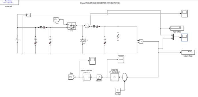
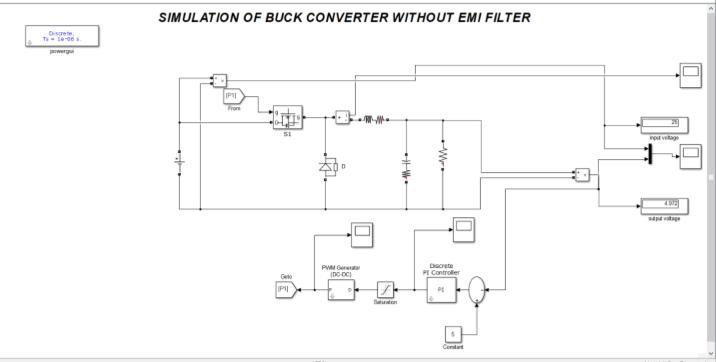
Fig-5: SimulationofBuckConverterwithoutEMIfilters.
Fig-6: SimulationofBuckConverterwithoutEMIfilters
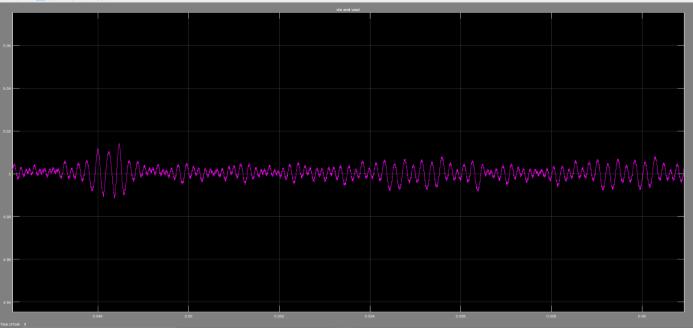
Without EMI filter in the buck converter, with an input voltageof25V,youcanseeclearlytheoutputvoltageripples rangingfrom~5.1Vto~4.9V.Thereforethereisadifference of+/-0.1Vthanthedesiredoutput.
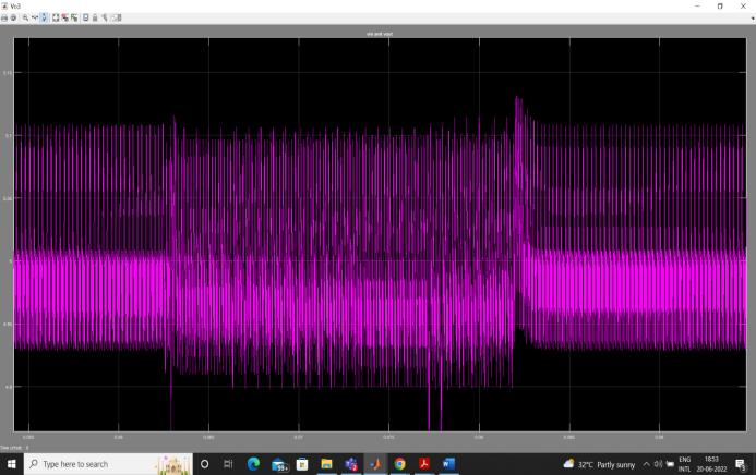
Fig-7: SimulationofBuckConverterwithEMIfilters.
International Research Journal of Engineering and Technology (IRJET) e-ISSN: 2395-0056
Volume: 09 Issue: 09 | Sep 2022 www.irjet.net p-ISSN: 2395-0072
higher DC input voltage (25V) to 5V DC output EMI free voltage.
[1] Liu Yitao, See Kye Yak, Electromagnetic Interference Filter Design, Nanyang Technological University, 28July2015.
[2] K.Manjula,B.E.,S.Bhuvaneswari,M.E.,(Ph.D).,AReview of Analysis andDesign of EMI Filters forPower ElectronicConverters,08Nov2015.
[3] J. L. Kotny, T.Duquesne, N. Idir,Design of EMI filtersforDC-DCconverter,02June2016.
[4] Konstantin Kostov, JormaKyyrä ,Analysis and Design ofEMI Filters for DC-DCConverters Using ChainParameters,TeuvoSuntioHelsinkiUniversity ofTechnology,24September2003.
WiththeadditionofEMIfiltertothebuckconvertercircuit, for the same input voltage of 25V, you can see clearly the output voltage ripples is drastically reduced ranging from ~5.01V to ~4.99V. Therefore there is a difference of +/0.01Vwhichisnegligiblethanthedesiredoutput.Hencethe desiredoutcomeisobserved.
For an EMI occurrence, there are always three basic components exist, the source, victim and coupling path. TherearetwotypesofconductedEMI,duetothedifference inpathundertaken,theCMNandtheDMN.TosuppressEMI effectively,thecouplingpathshouldbemadeasinefficientas possible,whichcanbeachievedthroughtheadditionofEMI filterstothenoisesource.
Since the EMI generated are high frequency signals, to suppresstheEMI,redirectionandblockageofthesesignals are needed. To redirect and attenuate the noise signals, capacitorsareused.Capacitorsofferlowimpedancetohigh frequencyandliningthemparalleltotheloadwillensurethe noisesignalsbeingbypassedinsteadofreachingthevictim. Toblockthenoisefromreachingthevictim,aninductorcan be inserted in series with the victim. Inductors offer high impedance at high frequencies but low impedance at low frequency.Hence,highfrequencysignals,suchasnoisewill experiencehighimpedanceandpreventitfromenteringthe victim.
A step-down power converter has been successfully designed and based on the measurement that was performed, the step-down circuit was able to convert the
[5] Magdy Saoudi, Ahmed El-Sayed, Hamid Metwally,Design and Implementationof ClosedLoop Control System forBuck Converter UsingDifferentTechniquesZagazigUniversity.22 June2021.
[6] RashidH.Muhammad,PowerElectronics-Circuits, DevicesandApplications,PrenticeHallIndia,2004
[7] BimbraP.S.,PowerElectronics,KhannaPublishers, 2007.
[8] http://en.wikipedia.org/wiki/Buckconverter