International Research Journal of Engineering and Technology (IRJET) e-ISSN: 2395-0056
Volume: 09 Issue: 08 | Aug 2022 www.irjet.net p-ISSN: 2395-0072

International Research Journal of Engineering and Technology (IRJET) e-ISSN: 2395-0056
Volume: 09 Issue: 08 | Aug 2022 www.irjet.net p-ISSN: 2395-0072
 Bodhisagar J. Tayade1 , P.S. Bajaj2
1PG Student (M.Tech. Design Eng.) Mechanical Engineering Department, SSGB College of Engineering and Technology, Bhusawal, Maharashtra
2Professor, Dept. of Mechanical Engineering, SSGB College of Engineering and Technology, Bhusawal, Maharashtra ***
Abstract - This report explains the rationale why mechanics play such a crucial role within the style of business trucks. it's established through the study of previous papers supported the sphere of auto mechanics howeverthepuremathematicsoftrucksaffectsmechanics and fuel consumption. rising the mechanics of business tractor-trailer units involves the installation of drag reductiondevicesinsureregionsofthetrucksubjecttothe foremost drag force. In preparation for the CFD (Computational Fluid Dynamics) study on model trucks a testsuitwasstudiedinitial.
Key Words: CFDBasics,Aerodynamics
The external mechanics of road vehicles have a robust influence on friction resistance, fuel consumption and stability.Thisprojectcanstudythemechanicsofsemi-trailer business trucks, wherever there's sturdy mechanics interference between the tractorand trailerunits, and far scoperemainsforimprovement.
The objectives of this project square measure clearly declaredasfollows;
•Tosummarizetheexplanationswhymechanicsanddrag reductionmaybeacrucialfacetofbusinessvehiclestyle.
•Todoareviewofthepresentassortmentofdragreduction devicesutilizedbytheindustry.
•TosimulatewithCFDtheinfluencedragsreductiondevices wearthegeneralcoefficientofaspecificmodeltruck.
In terms of road vehicles one amongst the foremost vital physics at play is mechanics. mechanics is a huge, well maturedfieldofsciencethussolelytheforemostapplicable aspectsaregoingtobementionedduringthisreportidest, the basics. the foremost applicable aspects of mechanics relative to vehicle motion include; the properties of incompressible fluids, external flow phenomena and consistencyeffects.
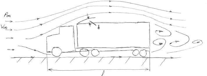
Fig. 1. Theflowfieldaroundacommercialtruck
In general, there square measure 2 flow phenomena in fluids, internal and external. Internal flow worries with motionwithinaconfinedareasortofapipeforexample.this kindofflowfielddoesn’trelatetovehiclemotionbecause thepassingairoveravehicleisn’tconfined.Forthisreason, solelyexternalflowphenomenaaregoingtobementioned.
In an overtaking or crossing maneuver on a highway involving two vehicles, the flow fields around the two vehicles interact generating transient aerodynamic forces that can affect car handling and stability [1]. When the relative size difference between the two vehicles is large (e.g.,betweenacarandatruck),theseforcesincreaseonthe smaller vehicle, and they increase even further under the influenceofcrosswinds,especiallywhentheovertakingcar is on the leeside of the truck [2]. A vehicle is more stable whenitsgeometriccenter,centerofgravity,andstagnation pointareallinline.Undercrosswind,theairflowaroundthe vehiclebecomesasymmetric,andthestagnationpointshifts towardsthedirectionofthecrosswind,affectingthestability of the vehicle [3]. As the computational power of commercially available computers has doubled approximately every two years (famously observed and predicted by Gordon Moore [4]), high quality transient computational fluid dynamics (CFD) simulations of the complex interactions between moving vehicles have not beenfeasibleuntilthelate2000s.Thisliteraturereviewis dividedintothreesectionsthatarebasedonthephysicsof the study (single vehicles, vehicle interaction, and vehicle interactioninthepresenceofcrosswinds.
2022, IRJET | Impact Factor value: 7.529 | ISO 9001:2008 Certified Journal |

International Research Journal of Engineering and Technology (IRJET) e-ISSN: 2395-0056
Volume: 09 Issue: 08 | Aug 2022 www.irjet.net p-ISSN: 2395-0072
Tsubokura et al. [5]conductedfull-scalesimulationsona singlepassengercarbyusingaLargeEddySimulation(LES) model that could reproduce unsteady turbulence characteristics with high accuracy. The simulation used about 38 million cells, and the resulting vortices and flow structureswerevisualizedindetailandvalidatedwithfullscalewindtunnelexperiments.Theyawangleofthevehicle was also changed, to mimic sudden crosswinds, and the change in the flow structures was investigated. The study showedtheadvantagesofusingLEStoprovideaerodynamic data on the different eddy structures around vehicles in comparisontoconventionalwindtunneltestsorReynoldsAveragedNavier-Stokes(RANS)simulations.Alaterstudyby Tsubokuraetal.[6]investigatedtheaerodynamicresponse totransientcrosswindsofa5percentscalemodelpassenger car by using LES and wind tunnel experiments validation. Unsteady and gusty crosswinds were considered in the study,showingallsixcomponentsofaerodynamicforcesand momentsineachcase.
Sterken et al. [7] usedtherealizablek-εturbulencemodel with standard wall functions and 90 million cells to investigate the wake-shape behind a passenger car. The moving ground and rotating wheels were simulated. Fullscale models were used for both the simulations and the experimental studies, and there was good correlation betweenthemintermsofdragcoefficient.Thewake-shape showedbothsimilaritiesanddifferences.
Usingaslidingmeshmethod, Wang et al. [8]conducteda three-dimensionalCFDstudyonthetransientaerodynamic forces occurring on a motorcycle overtaken by a truck, consideringthreedifferentlateraldistancesbetweenthetwo vehicles. Results showed the variation in forces and momentsonthemotorcycleduringtheovertakingprocess. However, the simulation used the Reynolds-Averaged Navier-Stokes (RANS) model and only 1.7 million computational cells. This model experienced difficulties capturingunsteadyflowcharacteristics[5].Noexperimental studieswereperformedtovalidatetheresults.
Astudyby Al Homoud et al. [9]conductedCFDsimulations onacarovertakingatruckbyusingfull-scalegeometries.It did not mention the turbulence model used in the simulations,andtherewasnoexperimentalvalidation.The resultsdidnotshowthevariationofforcesactingonthecar with time, as the study followed a quasi-steady approach.
Zhang et al. [10] conducted a transient CFD study on two vehiclescrossingeachotherbyusingk-εturbulencemodel; however,itisnotclearwhetherthegeometriesusedwere two-dimensional(2-D)orthree-dimensional(3-D).There wasnoexperimentalvalidationfortheresults.
Basara et al. [12], using a hybrid RANS/LES scheme (denotedasPANS,PartiallyAveragedNavier-Stokes[11]to perform CFD simulations on a car overtaking a truck, showedthatthedragonthecarincreasedtoitsmaximum
valuewhenthecarreachedthefrontofthetruck.Theresult was validated by experimental studies using 40 percent scaled models of both vehicles, fixed at eight relative positionsbetweenthetwomodels,thusapproximatingthe unsteadyprocesswithaquasi-steadyprocess.Thisincrease inforcesontheovertakingvehicleasitapproachedthefront of the overtaken vehicle was corroborated by similar experimentalstudiesconductedbyHowelletal.,performed at a 12.5 percent scale [2]. This wind tunnel study used a steppermotorandasystemofcablesandpulleystosimulate theovertakingmaneuverbetweentwovehicles(atruckand acar)forarangeofyawangles(-10oto+10o)andarangeof lateral separating distances. It estimated the incremental loads generated in such a maneuver, showing that these loadsincreasedinthepresenceofacrosswindwhenthecar wasontheleesideofthetruck.
A three-dimensional, CFD, quasi-steady study on a car overtaking a truck by Pasala et al. [13] assumed that the relativevelocitybetweentwovehicleshasanegligibleeffect ontheflowdistributionandtheforcesactingonthecar.This studylackedexperimentalvalidation.
Existingliteraturedataareinconclusiveregardingtheeffects ofovertakingvelocitywhenthesizedifferencebetweenthe two vehicles is significantly large (e.g., a car overtaking a truck).Itissuggestedthattheabsolutevelocityofthelarger vehicleisdominantindeterminingtheloadsonthesmaller vehicle[2].However,accordingtoShrefletal.[14],onthe basisofanon- roadexperiment,thelateral loadsona car overtaking a truck tend to increase linearly with the overtaking velocity. Simulations of the dynamic passing process between generic vehicles (Ahmed bodies) were conductedbyUystepruystandKrajnović[15]byusingthe URANSmodelandstudyingchangesintheforceandmoment coefficientsoftheovertakenvehicle.However,theAhmed bluffbodywastoosimplifiedtobeabletoprovideabasisfor drawingquantitativeconclusionsfromthesesimulations.
UponkickingoffanalyzingagivenflowdownsideinFluent the user is round-faced with 3 initial inputs; pure mathematics, meshing and downside setup. once process every input the matter is solved then brought into a post processortovisualizetheresults.
ThemethodologyfortheCFDanalysisconductedisoutlined duringthissectionofthereportforeveryofthesubsequent investigations;
International Research Journal of Engineering and Technology (IRJET) e-ISSN: 2395-0056
Volume: 09 Issue: 08 | Aug 2022 www.irjet.net p-ISSN: 2395-0072
ThepurposeoffindingoutsuchANelementaryformduring aprojectrelatingtovehicleaeromechanicsisprincipallyto induce a pity the computer code, however conjointly to determineavalidationcaseforfuturetruckmodels.instep with results documented by Frank M. White in ‘Fluid Mechanics’ edition five, the coefficient of drag of a cube immersedduringafreestreamflowfieldisone.07forflows withaSirJoshuaReynoldsvarietyoften,000orlarger[8]. Theflowduringthisinstanceisperpendiculartoafaceofthe cube. If the same drag coefficient is replicated it'd be an honest indication that correct CFD techniques square measurebeendeployedandanhonestindicationthatresults obtained for resultant truck models square measure moderatelycorrect.Thisinitial case,thecube,alsowillbe notedbecausetheactionthroughoutthereport.it'splanning tobevigorouslyanalyzedandtested.Asecondarypurposeof analyzing this case in such detail is to determine what influenceeveryoftheparametersinsidetheprogramwear theresults.informationofsuchinfluenceontheactionwill thenbeappliedtoresultantcases.
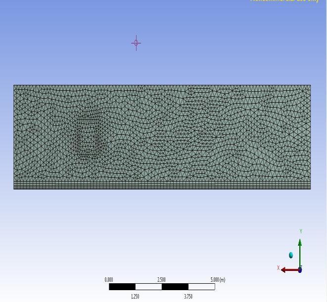
The initial mesh used a hundred and seventy,000 components with a most face size of zero.05m long. It’s necessarytonoticethiswassimplyassociatedegreeinitial approximationonthequantityofcomponentsandtheirsize neededtoduplicateWhite’scoefficient.Aalotofrigorous analysiswasperformedwhengettingaresultvictimization this initial mesh. Figure 0-3 below shows an image of the meshusedononly1planeofsymmetry
Forthiscasetheflowofairoveracubeisbeingstudied.an impressionvolumeforthisairisneededtoanalyzetheflow howeverit’snotclearhoweverhugeit'stobetoaccurately analyze it. once size the management volume one doesn’t wishtostyleittoohugeasaresultofthiscanincreasethe weather at intervals the domain and additionally the computing time. With this in mind Associate in Nursing initial enclosure was designed. Analysis was performed victimizationitandresultssquaremeasuredocumentedin Chapterfour.
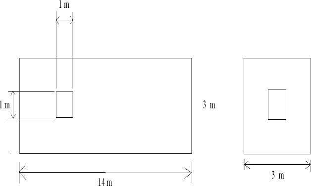
The problem consists of a 1m x 1m x 1m cube in an exceedingly massive enclosure. the scale of the enclosure waschosenas3maheadofthecube,10mbehinditand1m either side. This enclosure is simply Associate in Nursing initial one with many areas to the cubes rear to accommodateturbulencewithinthewakeoftheflow.
The problem was affected to 2 vital boundary conditions; associateflowofairpainterrangeoften,000orontopofand afree-streamflowcondition.Free-streamflowsuggeststhat thecubewon’tbestrickenbyphysicalphenomenongrowth from different surfaces. The painter range is that the quantitative relation of mechanical phenomenon force to viscousforceoutlined.
Thepainterrangeisten,000orontopof,thefluiddensity and body area unit constant at one.225 and zero.01206 kg/msseverallyandthereforethecharacteristic lengthis thatofthecube(1m).Inputtingtheseparametersintothis
International Research Journal of Engineering and Technology (IRJET) e-ISSN: 2395-0056
Volume: 09 Issue: 08 | Aug 2022 www.irjet.net p-ISSN: 2395-0072
equationleadstoarateofninety-eight.45m/s.thiscanbe therateneededwithinthesimulation.butsincetherequired painterrangeisten,000orontopofthiswillberoundedup toahundredm/sforsimplicity.Thevaluesemployedinthe CFDsimulationareaunitoutlinedinTableone.
Variable Quantity ρ 1.225 μ 0.01206 kg/m s L 1 m v 100 m/s
Apressurebasedmostlyconvergentthinkerwasemployed in the simulation as a result of for Associate in Nursing application like this (fluid flow over Associate in Nursing immersed body) that’s what's counseled by ANSYS Advantage [9]. The pressure based mostly convergent thinker in Fluent reduces the convergence time by the maximum amount as 5 times. It will this by finding momentumandpressurebasedmostlyequationsinavery coupledmanner[9].Thesimulationranemployingasteadystatetimedomainratherthanatransientone.thisisoftenas aresultoftheauthorwishedagentlestateresolutionwith allthefluctuationstimeaveragedout.
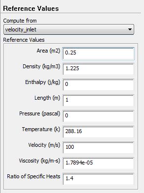
Theflowregimechosenforthisprimarysimulationwasthe fundamentalinvisidmodel.Thestipulationobligatoryonthe truckwasano-slipcondition.thissuggeststhespeediszero on all the surfaces of the truck. The reference values employedinthesimulationsquaremeasureoutlined
As will be seen from Figure 0-5. a reference space of was chosen. this is often as a result of the 2 symmetry planes usedquarterstherealmneededforthesimulation.Forthis simulationtheanswerwaysandcontrolswereuntouched, leftbecausethedefaultsettings.
Afterspecifyingthereferencevaluesamonitorfordragforce was created. The drag on the cube is that the solely drag force needed therefore this was given by selecting ‘cube’ belowthenamedpicks.Thedirectionwasconjointlygiven because the negative x-direction (-1,0,0). this is often the direction opposition the front face of the cube. A hybrid formatwaschosenoverthequalityformatasaresultofit expeditiouslyinitializestheanswerbasedmostlystrictlyon simulationsetup[9]thatmeanstheuserdoesn’tgottooffer extra inputs. Once the answer was initialized a call for participation of three hundred iterations was created and alsotheprogramcalculatedtheanswer.Theresultsforthis simulationardocumentedinChapterfour.1.
Based on the results from the initial enclosure it seems a more robust mesh is needed therefore a little mesh convergence study was undertaken. a correct mesh convergence study cannot properly be undertaken as a resultofthemostgridsizeissimplytoolittle.therefore,this mesh convergence study is actually additional of a mesh comparison.
Forthestudy 3gridsizes wereanalyzed; a roughmesh, a mediummeshandafinemesh,documentedinTableapair of.ThecoursemeshusedwassimplytheinitialmeshFluent createsaroundabodyofair.there'snorefinement.
2022, IRJET | Impact Factor value: 7.529 | ISO 9001:2008 Certified Journal | Page1276
International Research Journal of Engineering and Technology (IRJET) e-ISSN: 2395-0056
Volume: 09 Issue: 08 | Aug 2022 www.irjet.net p-ISSN: 2395-0072
Coarse mesh: 21,283 elements
Medium mesh: 104,898 elements
Fine mesh: 490,480 elements
Themediummeshcontainsroughlyahundredandfive,000 parts.themostdistinctionbetweenthismeshandtherefore thecourseoneisthatthecomponentfiller.thedimensionsof associate parts face during this mesh were restricted to a mostzero.6m.Thisaccumulatedthecellcountfromtwentyone,000to105,000parts.
Forthefinemesh,advancedfillerfunctionswereemployed inFluent’smeshingapplication.Theadvancedfillerperform chosenwasproximityandcurvature.Thisyieldsasmaller component size the nearer the mesh is to the sides of the cube. A medium connectedness Centre was chosen that evoked a two hundredth rate for the weather. A slow componenttransitionratewasperthiscaseasaresultofits additional suited to CFD analysis than a quick transition thankstotheveryfactitfillsthedegreewithpartsadditional swimmingly and expeditiously. The minimum component size was nominative as zero.01m even supposing the programinallprobabilitywon’tproducepartsthistiny.The minimum size here isn't that necessary. the utmost componentsizeisbut,anditabsolutelywassettozero.12m. With these settings in situ the grid size accumulated to 490,480parts.Acomparisonmaybeseenofthecoarsegrid andthereforethefinegrid
There square measure 2 variations though; a flow regime study ANd an upwind theme study. A a lot of elaborated investigationwentintotheflowregimeandupwindtheme resolutionstrategies.FortheflowregimeinvestigationAN inviscid model, stratified model, commonplace and realizablek-epsilonmodelsbesidecommonplaceandnonequilibriumwallfunctionswereallcomparedagainstevery of the 3 mesh sizes. The results of that square measure documentedinFigure4-0-1.Thisanalysiswascarriedsoas to spot what impact every model had on the general coefficient.Near-walltreatmentisvital|vital|important}in externalmechanicsthereforeitabsolutelywasadditionally importanttolookatcompletelydifferenttreatmentsoffered inFluent.the2closestowalltreatmentsthought-aboutwere commonplace wall functions and non-equilibrium wall functions.
Theproposedworkresultsinidentifyingsufficienttolerance in changing the material (EN 8 steel & EN 24 steel). It is expressedinmethodologyas,
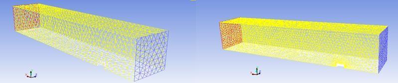
Fig. 7. Comparisonofthecoarsegrid(left)andthefine grid(right)
Noticethedenseclusterofcomponentsinrealtimeround the cube within the fine grid. this can be due to the slow transitionandproximityandcurvatureoperateused.Once themeshwascreatedtheNamedalternativeswereselected asbefore.
Theproblemwasoutlinedinforthemostpartanequivalent methodforthesecondenclosurebecauseitwastheprimary.
Wehavedecidedtocompletetheprojectinsimplewaterfall model,

Communicationphaseincludes:
• Discussionoftopicwithguide
• Actualfarmvisitandunderstandingvariousfarming method
• Literaturesurvey
• Problemidentification
International Research Journal of Engineering and Technology (IRJET) e-ISSN: 2395-0056
Volume: 09 Issue: 08 | Aug 2022 www.irjet.net p-ISSN: 2395-0072
• Analysisofproblem
Conceptdevelopment • Discussingvariouscertaintiesanduncertainties
Planningphaseincludes:
Processplanning
Rawmaterialplanning
Forceanalysis
Processscheduling
Modelingphaseincludes:
Designofvariouscomponents
CADmodelingofcomponents
Assemblymodelofcomponent
Prototypemodelmaking
Constructionphaseincludes:
Selectionofpropermanufacturingmethods
Workingasperprocessschedulingandplan
Testingofequipmentonfield
Erroranalysis
Repairifany
Comparingtheprojectwiththedesignedoutput
Preparationoftestingresults
Preparationofprojectreport
Finalsubmissionofproject
Before we proceed to the process of manufacturing, it’s necessarytohavesomeknowledgeabouttheprojectdesign essential to design the project before starting the manufacturing.Maximumcostofproducingapartofproduct isestablishedoriginallybythedesigner.
Designprocedure:
Whenanewproductortheirelementsaretobedesigned,a designermayproceedasfollows:
Make a detailed statement of the problems completely;itshouldbeasclearaspossible&also ofthepurpose
forwhichthemachineistobedesigned.
Make selection of the possible mechanism which willgivethedesiremotion.
Determine the forces acting on it and energy transmittedbyeachelementofthemachine
Selectthematerialbestsuitedforeachelementof themachine.
Determine the allowable or design stress consideringallthefactorsthataffectthestrengthof themachinepart
Identify the importance and necessary and applicationofthemachine
Problemswithexistingrequirementofthemachine productivityanddemand.
Fromtheanalysisconductedduringthisreportsomevital conclusionsmaybedrawn.TheflowoverANimmersedbluff bodyisnearlyentirelypressurebasedmostly.Theresults show the contribution of skin friction to the general coefficientisnegligible,but1Chroniclesinmostsimulations. this means that so as to boost vehicle mechanics, the variables within the equation that govern pressure drag square measure the sole variables of importance once comingupwithmechanicsbluntbodies.allsortsoftrucks maybethought-aboutbluntbodiesbecauseoftheirnatural cuboidpuremathematics.
Whenanalyzingthesimulationsofthecubeitmaybeexplicit that for the given mesh sizes used, very little distinction existsbetweenanyofthevariedflowregimesusedandany of the upwind answer schemes used. The coefficient calculated,mistreatmentANinviscidmodelandinitialorder upwindanswerthemeforMeshtwo,issimply100%offthe coefficient calculated for Mesh three with a second order upwindanswertheme,andrealizablek-epsilonmodel.This little distinction poses a motivating question; however, correct do i desire a answer to be, given the additional computationvalueandcomplexnessoftopqualitymeshes, difficult turbulence models and better order upwind schemes?forseveralfunctionsaballparkresultatintervals plus/minus100%oftheparticularanswerisadequate.This
2022, IRJET | Impact Factor value: 7.529 | ISO 9001:2008 Certified Journal
International Research Journal of Engineering and Technology (IRJET) e-ISSN: 2395-0056
Volume: 09 Issue: 08 | Aug 2022 www.irjet.net p-ISSN: 2395-0072
tolerancelevelbutwouldn'tanswerwithinthestyleofdrag reduction devices as a result of such devices would solely improvedragbyamostof30-50%,whichmeanseachper centiscrucial.
Withrelevancyenclosurestyleforcubes,itabsolutelywas foundthatalittlesizeleadstoablockageimpactmadeby the cube leading to a better coefficient because of the pressurizedforceexertedbytheair.Enlargingtheenclosure eliminated this impact and an identical answer to Whites wasobtained.Analysisconductedonthepressurecontours ofthecubeshowedanoutsizedpressuregradientbetween the front face subject to the flow and also the rear face withinthewakeoftheflow;theexplanationforthispressure gradientisexplainedinChapterone.
Results from the interference gap investigation indicate a linearrelationshipbetweenthecoefficientandalsothegap breadth;thisrelationshipwantsadditionalconfirmationbut asnoneoftheliteraturereviewedasapartofthisproject reportedanyrelationshipbetweendragandgapwidth.Upon analyzing the pressure distribution on every of the truck surfaces,itabsolutelywasdiscoveredthatanyexplicitface ofthetruckwassubjecttoeitherpressuredragorfriction draghowevernoteach.Thefacesperpendiculartotheflow wereaccountableforthepressure dragandalsothefaces tangentialtotheflowwereaccountablefortheskinfriction. thisisoften whatwas expectedtohappenas explainedin Chapterone.Thedevicestyleappliedasapartofthisproject wasself-madeinthisdragreductionofuptohalf-hourwas recorded with the models used. This study concerned AN repetitive style method however it ne'er reached AN improvementpurposeforthedevicegeometry;thismightbe studiedinadditionaldetailduringalaterFinalYearProject.
The cross-wind study was conjointly self-made. Incoming wind occurrence on the truck at 5° angle intervals was studied. Monitors for the drag force within the axial direction of the truck were created and solutions were examinedandcomparedtoonesrecordedbyHuchoin[3]. Similar trends within the relationship between coefficient andwindanglewerediscoveredbetweenresultsrecorded duringthisprojectandpeoplerevealedbyHucho.finally,the riseinwindAnglecorrespondstoariseindragforceupto an angle of roughly 20° once that purpose it reduces by a similar rate. The drag increase because of the wind angle wascombatedvia a tanglereductiondeviceplaced within theinterferencegap.Atthe30°windanglethegapblocker reduces the drag by pure gold in step with the simulated results.
Conclude, there square measure huge advantages to be gained from putting in drag reductiondevices tocategory eight trucks. As explicit in Chapter one fuel consumption reliesonmechanicsdrag,thusbyreducingthedragforceby means that of add- on devices, transportation firms with fleetsoffuelthirstytruckswillsavesubstantialcashonfuel.
[1] Li Song, Zhang Jicheng, Liu Yongxue, Hu Tieyu, “AerodynamicDragReductionDesignofVanBodyTruck by Numerical Simulation Method,” in Second International Conference on Digital Manufacturing & Automation,Changchun,2011.
[2] U.S.DepartmentofEnergy,TransportationEnergyData Book,OakRidge,Tennessee,2012.
[3] W.-H. Hucho, The Aerodynamics of Road Vehicles, 1988.E.
[4] Mu Wang1, Qiang Li, Dengfeng Wang, Changhai Yang, Jinlong Zhao, Guijin Wen, “The Air-deflector and the drag:ACaseStudyofLowDragCabStylingforaHeavy Truck,”Jinan,2009.
[5] R.Drollinger,Heavydutytruckaerodynamics,Societyof AutomotiveEngineers,1987.
[6] R. Wood, “A Discussion of a Heavy Truck Advanced AerodynamicTrailerSystem,”2010.
[7] J. Eaton, “Session 26: Computational Fluid Dynamics,” Galway,2013.
[8] F.White,FluidMechanics,WCBMcGraw-Hill,2005.
[9] Ansys,“AnsysAdvantageVolume5issue1,”2011.
[10] M. Lanfrit, “Best practice Guidelines for Handling Automotive External Vehicle Aerodynamics with FLUENT,”Darmstadt,2005.
[11] F. Browand, “Reducing Aerodynamic Drag and Fuel Consumption,”2011.
[12] F.-H. Hsu, “Drag Reduction of Tractor-Trailers Using Optimized Add-On Devices,” American Society of MechanicalEngineers,LosAngeles,2010.
[13] Subrahmanya Veluri, Christopher Roy, “Joint Computational/Experimental Aerodynamic Study of a SimplifiedTractor/TrailerGeometry,”AmericanSociety ofMechanicalEngineers,Blacksburg,2009.
[14] T.Favre,“AerodynamicSimulationsofgroundvehicles inUnsteadyCrosswind,”2011.
[15] F.-H. Hsu, “Design of Tractor-Trailer Add-On Drag ReductionDevicesUsingCFD,”LosAngeles,2009.