
International Research Journal of Engineering and Technology (IRJET) e-ISSN: 2395-0056
Volume: 12 Issue: 01 | Jan 2025 www.irjet.net p-ISSN: 2395-0072
International Research Journal of Engineering and Technology (IRJET) e-ISSN: 2395-0056
Volume: 12 Issue: 01 | Jan 2025 www.irjet.net p-ISSN: 2395-0072
Voleti Narayana Chandra Vamsi, Anisa Kumari, Mr.R.Karthikeyan
VOLETI NARAYANA CHANDRA VAMSI Puducherry
ANISA KUMARI Andaman & Nicobar Islands
Mr.R.KARTHIKEYAN, Dept Of Civil Engineering, Achariya College Of Engineering Technology, Puducherry, INDIA
Abstract - This paper presents a study that analyzes and designs steel members or sections used in the construction of steel structures, focusing on a comparative study of two different sections. Modern steel buildings are increasingly being constructed as high-rise structures in metropolitan areas. These buildings are designed to support vertical gravity loads and lateral loads, such as seismic and wind loads.In this project, we consider a G+10 framed steel structure. The analysis and design are carried out using STAAD.Pro V8i software, with the results discussed in detail. The analysis and design of the steel sections include calculations for dead load, live load, wind load, seismic load, temperature load, and load combinations, all in accordance with the Indian Standard Code of Practice: IS 800:2007, which governs general construction in steel. IS 875 (Part 1) - 1987, which specifies design dead loads (unit weights of building and stored materials) for buildings and structures, and IS 875 (Part 2) - 1987 are among the pertinent codes., which outlines conservatively imposed loads for buildings and structures; IS 875 (Part 3) - 1987, which details design wind loads for buildings and structures; and IS 18932002/2005, which specifies the design of seismic loads for buildings and structures. According to the Bureau of Indian Standards (BIS) code (i.e., IS: 875), thermal forces are combined with other loads using a load factor of 1.0. In this study, we compare and discuss the nodal displacement, axial force, shear force, bending moment, and storey drift that occur in the overall structure under different loading conditions in the +X direction.
Keywords: Steel Framed building, Staad Pro V8i, Wind Load, Seismic Load, Bending Moment, Shear Force, Axial Forces,storeydrift,Nodaldisplacement,Multi-storey.
1.1 General
Our project focuses on the analysis and design of a G+10 high-rise building using STAAD Pro V8i, chosen for its user-friendly interface, compliance with Indian StandardCodes,andversatility.
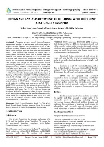
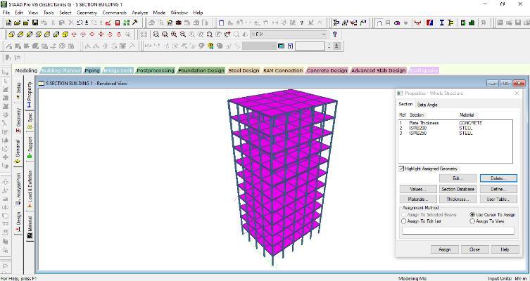
WewilldesignasteelstructurewithSandWsections.For the S section, we will use ISMB 200 beams and ISMB250 columns, while the W section will feature
IW500350×2040 beams and IW600350×2040 columns. Both designs will have a 150 mm thick concrete slab and willaccountforvariousloads,includinglive,dead,seismic, wind,andtemperatureloads.Wewillcomparethemodels based on nodal displacement, axial forces, shear forces, bendingmoments,andstorydrift.
Structural design combines art and science to create safe and durable structures, requiring creativity and a strong understanding of engineering principles and designcodes.
OurfocusisonaG+10residentialbuildingwitha floor-to-floor height of 3 meters, utilizing STAAD Pro for analysis.Typical designproblemshave beenaddressed to demonstratethesoftware’sapplicationperIScodes.
STAAD Pro is equipped with advanced visualization tools and analysis capabilities, suitable for various structures, including buildings and bridges. Engineers gather essential data on loads, geometry, and materials to conduct accurate analyses, with results informing assessments of stresses, displacements, and stability.
Steel is a crucial construction material known for its rigidity and high strength-to-weight ratio. It is commonly used in buildings, including houses, warehouses, hangars, educational facilities, bridges, and stadiums. The advantages of structural steel include its adaptability, high strength, cost-effectiveness, quick construction,easeofrepairormodification,andreliability.
Keypropertiesofstructuralsteelinclude:
Density:Rangesfrom7750to8100kg/m³.
Young'sModulusofElasticity:Between190and210GPa. Poisson'sRatio:Rangesfrom0.27to0.3.
TensileStrength:Hightensilestrengthpreferredover othermaterials.
YieldStrength:Rangesfrom187to758MPaforcarbon steeland366to1793MPaforalloyedsteel.
ShearStrength:About0.57timestheyieldstress.
International Research Journal of Engineering and Technology (IRJET) e-ISSN: 2395-0056
Volume: 12 Issue: 01 | Jan 2025 www.irjet.net p-ISSN: 2395-0072
Hardness:Variesforalloys,typicallyfrom149to627kg forstructuralsteel.
SpecificHeat:Forcarbonsteel,rangesfrom450to2081 J/kg·K.
1) Based on Carbon Content
CarbonSteel:Containsupto2%carbon;ultimatetensile strengthof410–440MPa.
High-StrengthCarbonSteel:Usedintransmissionlines; tensilestrengthof480–550MPa.
Micro-AlloyedSteel:Enhancedductility;tensilestrengthof 440–590MPa.
QuenchedandTemperedSteel:Heat-treatedforstrength; tensilestrengthof440–590MPa.
WeatheringSteel:Corrosion-resistant;tensilestrengthof 480MPa.
Fire-ResistantSteel:Thermo-mechanicallytreatedforfire resistance.
2) Based on Shapes and Forms
Structuralsteelmembersinclude:
-I-Sections(BeamSections)
-ChannelSections
-TeeSections
-AngleSections
-Bars -Tubes -Flats
-Sheets
This condensed version maintains the essence of theoriginalcontentwhilebeingmoreconcise.
Steel structures are assemblies of structural steel shapesthatareconnectedbywelding,bolting,orriveting. Whilesteelconstructionsmustbechosenfromthemarket, the majority of concrete structures are cast in-situ. In concrete constructions, joints are monolithic, while in steel structures, individual elements must be joined using specific techniques. Connections and features in steel constructions must be engineered to withstand anticipatedforces.Almostanykindofstructure,including skyscrapers, bridges, industrial buildings, high-rise buildings,etc.,ismadeofsteel.
1.4
Originally, STAAD Pro was developed by Research Engineers International in Yorba Linda, California. Late in 2005, Bentley Systems purchased Research Engineers International. Structures such as bridges, towers, skyscrapers, transit systems, industrial facilities, and utility structures may all be evaluated and constructed with STAAD Pro, a tool for structural analysis and design.
With STAAD Pro V8i, you can evaluate and design any engineeringstructure.
This software makes it easier to create 3D models, multi-material designs, and framed buildings. In line with the grid-like structure architecture, it offers modeling tools and templates, code-based prescriptions, analysis techniques, and solution approaches. The STAAD Pro V8i version supports both simple and complex systems and enables evaluations in both static and dynamic scenarios. Applications of various complexity can be easily created because to its integration features and intuitive UI. For designs ranging from basic 2D frames to intricate contemporary high-rises, STAAD Pro is a well-structured andeffectivetoolbecauseofitsconnectivitywithmultiple designanddocumentationplatforms.Thefollowingdetails areincludedinthischapter:
1.StructuralSystemModeling
2.Design,Analysis,andLoading
3.InteroperabilityandOutputVersatility
1.5 Terms and Definitions
Thestoreyheightdividedbythestoreydrift the lateral displacement of one level relative to the floor below is the storey drift ratio. When analyzing the effects of lateral stress brought on by seismic or wind loads on a multi-story building, the storey shear and storey drift graphs offer a useful narrative. There are graphs that show the displacement distribution by altitude.
When a structural member is exposed to an external force or moment, it reacts by bending, a phenomenon known as a bending moment. The most commonorfundamentalstructuralelementthatissubject to bending moments is the beam. In other words, the resistance to a member's rotation that arises from applying load to the structure at a distance from the reference point is known as the bending moment. The kind,intensity,anddistanceoftheloadfromthereference point all affect the applied moment. The bending moment isalsoinfluencedbythetypeofsupport.
Shear force, like the airflow pressure across an airplane wing, is a force that acts parallel to a surface or crosssectionofabody.Italludestothisforce'scapacityto sever surfaces. The tangential component of an applied force is what causes shear force, which operates tangentially. Through shear resistance, the body opposes this force, causing its cross-section to deform and generating shear strain and shearing stresses. The parts thatfollowwillprovidemoreinformationonshearforce.
International Research Journal of Engineering and Technology (IRJET) e-ISSN: 2395-0056
Volume: 12 Issue: 01 | Jan 2025 www.irjet.net p-ISSN: 2395-0072
Axial force is a force that acts along the axis of a body. This type of force can be either tensile, which pulls the body apart, or compressive, which pushes the body together.
1.5.5
Multi-storey buildings provide an effective solution for affordable living spaces and dense settlements.
The structure of a multi-storey building typically incorporatesthefollowingelements:
Framed structure: Forms the basic foundation of thebuilding.
Propped structure: Provides a platform for supportingcolumns.
Suspended structure: Features horizontal floors supportedbyhigh-strengthsteelcables.
Cantilever structure: Eliminates the need for columnsincertainareas.
Braced structure: Uses braced frames to reduce lateral displacement and bending moments in columns.
Shear wall structure: Counteracts lateral forces andwindpressures.
Core structure: Houses lifts, stairs, and other verticalservices.
Tube-in-tube structure: Consists of the central tube that houses the building's utilities and services.
1.5.6
Building plans are detailed graphical representations that depict how a building will look after construction. They are essential for builders and contractors in constructing various types of structures. Additionally, building plans help estimate project costs and prepare budgets by outlining the design, materials, and dimensions needed, allowing for effective financial planningandresourceallocation.
1.5.7
An image that depicts a building or structure's height,length,width,andlookiscalledanelevation.
2.1
The structure should be safe, stable and don’t collapseunderappliedload.
Provide complete set of drawing for practical uses.
Study and analysis of output of steel structure in staadproV8isoftware.
To evaluate the response of Steel framed structure in terms of displacement, Support reaction,storeydrift.
To study about node displacement, axial force, shearforce,bendingmomentandstoreydrift.
Tousesoftwaretogatherdataformodelling
Steel Multi-storeyed building with two different sectionsusingStaadproV8i
To perform analysis of the multi-storeyed steel buildinginZoneII
To understand the behaviour of two steel structureswithdifferentsections.
To know the behaviour of steel structures under differentloadssuchasDeadload,Liveload,Wind load, Temperature loads, Seismic load and combinationsofloadsforagivenarea.
To compare both the results obtained from Staad proV8isoftwarewithdifferentsections.
3.METHODOLOGY
INTRODUCTION
LITERATURECOLLECTION&STUDY
SELECTIONOFPARAMETERS
MODELLINGOFSTEELBUILDINGUSINGSTAADV8i
DESIGNOFSTEELSTRUCTURE
PERFORMANALYSISOFSTRUCTURE
COMPARISONOFANAYTICALRESULTS
RESULTANDDISCUSSION
CONCLUSION
International Research Journal of Engineering and Technology (IRJET) e-ISSN: 2395-0056
Volume: 12 Issue: 01 | Jan 2025 www.irjet.net p-ISSN: 2395-0072
4.1
IS 800:2007 - Guidelines for general steel construction.
IS875(part1)-1987Thedesigndeadloads(unit weights of building and storage materials) for buildings and structures are provided by Indian StandardCodes.
IS 875 (part 2) - 1987: Indian Standard Codes specify conservative load limits for buildings and structures.
IS 875 (part 3) - 1987: Indian Standard Codes specifies wind loads for building and structure design.
IS1893-2002/2005: Indian Standard Codes provides design of seismic loads for building and structures.
As per the BIS code (i.e. IS:875), The thermal forcesaredisplayedwithaloadfactorof1.0when pairedwithotherloads
4.2
Structural loads play an essential role in the design of buildings. Building regulations require that structures are designedandbuilttoendureallpossibleforcestheymight facethroughouttheir operational lifespan; while ensuring theyremainfunctionalandsuitableforuse.
4.2.1
All fixed components of a building contribute to dead loads, which include the weights of walls, partitions, floor finishes, and other permanent features. These loads are calculated based on the dimensions and unit weights of elements, with typical unit weights being 24 kN/m³ for plainconcreteand25kN/m³forreinforcedconcrete.Dead loadsareconsideredstaticorpermanentandarecounted only after materials are permanently installed. The standard IS 875 (Part 1) – 1987 provides guidelines on unitweightsofbuildingmaterials.
Imposedloads,orliveloads,arecreatedbyhowa building is used, including the weight of movable partitionsandchanging factorslikeimpact,vibration,and maintenance activities. These temporary loads also account for occupants, tools, and items like planters. In bridges, live loads come from vehicles passing over. It's important to note that imposed loads exclude environmental factors such as wind, seismic forces, snow loads, and temperature changes, as well as structural issueslikecreeporunevensettling.
4.2.3
Air in motion with respect to the earth's surface is called wind. The earth's rotation and variations in terrestrial radiation are thought to be the main causes of wind. Convection, either upward or downhill, is mostly caused by radiation impacts. At high wind speeds, the wind often travels horizontally toward the ground. Vertical winds are always labeled as such since the name "wind"virtuallysolelyreferstothehorizontalwinddueto the comparatively minor vertical components of atmospheric motion. Wind speeds are measured with anemometers, sometimes referred to as anemographs. They are often placed at meteorological observatories at elevationsbetween10and30metersabovetheground.
Togetthedesignwindvelocityatanyheight(Vz) for the selected structure, the fundamental wind speed (Vb) for any site must be derived from or altered to incorporate the following effects: degree of risk; local topography, structure height and size, and terrain roughness.
Amathematicalexpressionforitisasfollows:
Where,
Vz = design wind speed in meters per second at anyheightz
k1 =probabilityfactor(riskcoefficient)
k2 = terrain, elevation, and the structure's size, and
k3=topographyfactor
a. The Risk Coefficient (k1 Factor) indicates fundamental wind speeds for Category 2 terrain at 10 meters above ground level, based on a 50year mean return period. Buildings must be designed using a regional basic wind speed for thistimeframe.
b. Whenevaluatingwindimpacts,thek2factor takestopography,height,andstructuralsizeinto account.
Terraintypesarecrucialfordesignandinclude: Category 1: Unobstructed open landscape with objectsunder1.5m.
International Research Journal of Engineering and Technology (IRJET) e-ISSN: 2395-0056
Volume: 12 Issue: 01 | Jan 2025 www.irjet.net p-ISSN: 2395-0072
Category 2: Open terrain with sparse obstacles 1.5–10mhigh.
Category 3: Areas with closely spaced obstacles upto10m.
Category 4: Terrain with many large, closely spacedobstacles.
c. The topography (k3 factor) influences wind speed, accounting for site elevation but not local features like hills or valleys. Wind can accelerate onhilltopsanddecelerateinvalleys.
Wind Pressures and Forces on Buildings/Structures:
A building's wind load must be determined for the followingreasons:
a. thebuildingoverall,
b. specific structural components such walls and roofs
c. Separate cladding units, complete with glazing andfasteners.
The wind pressure at any height above mean ground level will be calculated using the relationship between windspeedandwindpressureasfollows:
Where,
=windpressureatheightzinN/m2.
=designwindspeedatheightzinm/s
Onecandeterminethedesignwindpressurepd asfollows:
Where,
=Winddirectionalityfactor
=Areaaveragingfactor
=Combinationfactor
Pressure Coefficients - The pressure coefficients are always given for a specific surface or area of a building's surface. The area of a surface or a suitable piece of it is multiplied by the pressure coefficient (C) and the design windpressureatthesurface'selevationabovetheground to determine the wind load acting normal to that surface. Next, the wind load, F, acting perpendicular to the individualcladdingunitorstructuralelementis:
( )
Where,
Externalpressurecoefficient,
=internalpressurecoefficient
A=surfaceareaofastructuralcomponent
=designwindpressure
Seismic loading refers to the application of earthquakelike forces on structures, primarily at their contact points with the ground or nearby structures. The first step in earthquake engineering is to calculate the overall design lateral force, which is then distributed across different floor levels based on diaphragm action. Dynamic analysis, which determines the design seismic force distribution, appliesto:
1.RegularBuildings:Structuresover90metersinZonesII andIII.-Structuresover40metersinZonesIVandV.
2.IrregularBuildings:Framedstructuresover12metersin ZonesIVandV,andover40metersinZonesIIandIII.
Although not required, dynamic analysis is suggested for irregular buildings under 40 meters in Zones II and III, using either the Response Spectrum Method or the Time History Method, while comparing design base shear (VB) frombothmethods.
Earthquake Zones in India.
India has four seismic zones (II, III, IV, and V), withZoneIbeingexcludedfromclassification.
Zone V: High-risk area for earthquakes with intensity MSK IX or higher, with a zone factor of 0.36. It includes regions like the Andaman and Nicobar Islands andtheHimalayas.
ZoneIV:PronetoMSKVIIIintensityearthquakes, classified as a High Damage Risk Zone, with a zone factor of0.24.
ZoneIII:SimilartoZoneIV,alsoexperiencingMSK VIIIearthquakeswithazonefactorof0.24.
Zone II: Low Damage Risk Zone for earthquakes withintensityMSKVIorlower,withazonefactorof0.10, indicating a maximum horizontal acceleration of 10% of gravitationalacceleration.
The term "thermal load" refers to high temperatures that have an impact on any construction,
International Research Journal of Engineering and Technology (IRJET)
Volume: 12 Issue: 01 | Jan 2025 www.irjet.net
including the temperature of the air outside, the temperature of the air inside, the temperature of the air underground, the temperature of the heat source equipmentinsidethebuilding,andthetemperatureofthe materialstoragetanks.Thermalstress,whichistheresult ofthermalload,iscausedbytemperaturechangesinboth structuralandnon-structuralmembers.
5.1 Building Configuration
The model of the following buildings is developed to performtheresponseinStaadPro.V8i:
1. SteelframedbuildingwithS-Section 2. SteelframedbuildingwithW-Section SL.NO
1.
2.
Table 5.1 BuildingConfiguration
Withtheabove-mentioneddata,twotypesofSteelframed buildingsaremodelled:
1. MODEL1-SteelframedbuildingwithS-Section
2. MODEL2-SteelframedbuildingwithW-Section
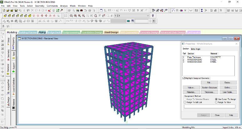
5.2 Plan Of The Building:
Figure 5.3 PlanoftheBuilding
International Research Journal of Engineering and Technology (IRJET) e-ISSN: 2395-0056
Volume: 12 Issue: 01 | Jan 2025 www.irjet.net p-ISSN: 2395-0072
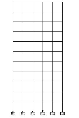
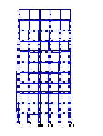
Figure 5.4 ElevationoftheBuilding
6.DESIGN AND ANALYSIS
6.1 Step by Step Procedure for Analysis Steel Framed Building in Staad Pro V8i
Step 1: Start Project:
Start New Project >Write down file name >Select space, locationandunits>Addbeam>Finish.
STEP 2: Create a new model:
To Select geometry > Run Structure Wizard > Model type FrameModel>BayFrame>Apply>ok.
i.LengthofthebayalongX-direction,L=15m
ii.WidthofthebayalongY-direction,W=12m
iii.Heightofthebuilding,H=33m
iv.NoofbaysalongX-direction=5
v.NoofbaysalongY-direction=4
vi.NoofbaysalongHeight=11(G+10)
Transferthemodel.
STEP 3: To create Continuous slab for the flat slab
GotoFrontview>Cutsection>selecttoview>Ok>Cut bottomsection
AddPlate>Selectallthe4nodepointsusingNodeCursor >Displaywholestructurecommand
Select plate cursor > Select plate > Translational repeat > SelectYdirection,no.ofsteps=10,spacing=03m>Ok
STEP 4: Assign the property of the beam, column, and slab:
Go to general > Section database > Select Indian > Select section>Close>Thickness(0.15m)>Add>Close
Go to Tools > Create new group > Group name: beam, column, and slab > Select the members > Associate the property
STEP 5: Assign the support
Go to front view > Support > Create > Fixed support > Assignallthebottomnodes>ok
STEP 6: Define Load
Loadanddefinitions> Definitions>Seismicdefinitions> Add>Selecttype:IS1893-2002/2005>Include1893part 4>Generate
Seismicparameters>Select:city,zone-2(Z=0.1),response reduction (steel moment resisting frame design =5, building type=all general building (IF=1.0), soil type= soft soil, structure type= steel frame structure and damping ratio=5%>Add
Clickonzone2,RF=5 >Add
Self-weight > Factor 1 >Add Member weight > Loading type > UNI > Write the value of weight > Assign the selectedbeam>Assign.
Definitions>Winddefinitions>Wind>Add
Selectwindload>Add>Selectcustom>Selectcal.Asper ASCE 7-2010 > Category II > Basic wind speed= 50m/s >Exposure–B>Apply>Selectmainbuildingdata:height, length and width >Apply > Select windward for design pressure>Apply>Ok
Add>Exposurefactor1>Assigntoview>Close
STEP 7: Load Case Details
LoadCaseDetails>Add>Define>LoadingType=Seismic Load>EX,EZ>Add>X&Zdirection,factor=1>Close
Define>Loadtype=DeadLoad>DL>Self-weight=1>ok
Define>LoadType=LiveLoad>LL>Selfweight= -4.5> ok
International Research Journal of Engineering and Technology (IRJET) e-ISSN: 2395-0056
Volume: 12 Issue: 01 | Jan 2025 www.irjet.net p-ISSN: 2395-0072
Load case Details > Define > Load type= Wind load –WX, WZ>Add>Windfactor>Add>Close
Define > Load Type = Temperature Load > TL > Select TL >Add> Temperature Differential from Top to Bottom > Add>Close.
STEP 8: Assigning of Loads
SelectEX,EZ>Assigntoselected>Assign>Yes
SelectDL>Assigntoview>Assign>Yes
SelectLL>Assigntoview>Assign>Yes
SelectWXWZLoad>Assigntoview>Assign>Yes
SelectTL>Assigntoview>Assign>Yes
6.2
6.2.1 Parameters of Steel Sections For W-Section
W-SECTION
Bf (mm) 250
Tf
Iz(cm4)
Ix(cm4)
Iy(cm4)
Zx(cm3)
Zy(cm3)
Table 6.1 ParametersofW-section
For S-Section
Tw(mm) 5.70 6.90
Iz(cm4) 2115.00 5132.00
Ix(cm4) 10.60 25
Ct (cm) 2.20 2.70
Iy(cm4) 137.00 335.00
Zx(cm3) 240.00 466.00
Zy(cm3)
Table 6.2 ParametersofS-section
6.2.2 Calculation of Member Weight
i. ISMB 200:
Area=30.80cm2=30.80×10⁻⁴m2
Unitweightofsteel=78.50kN/m3
Member weight= kN/m =0.24178kN/m
ii. ISMB 250:
Area=47.60cm2=47.60×10⁻⁴m2
Unitweightofsteel=78.50kN/m3
Member weight= kN/m=0.37366 kN/m
iii. IW500350×2040:
Area=353.00cm2=353×10-4m2
Unitweightofsteel=78.50kN/m3
Member weight= kN/m=2.77105 kN/m
iv. IW600350×2040
Area=402.00cm2=402×10-4m2
Unitweightofsteel=78.50kN/m3 S-SECTION
International Research Journal of Engineering and Technology (IRJET) e-ISSN: 2395-0056
Volume: 12 Issue: 01 | Jan 2025 www.irjet.net p-ISSN: 2395-0072
Member weight= kN/m= 3.1557 kN/m
6.2.3 Design for Bolted Connection
Bolted connection to column
For,M20grade4.6boltsandan8mmthickendplate
i. Theshearcapacityoftheboltinsingle-shear
( ) = √ ( ) =46.38kN
ii. Bearing capacity of bolt-on an 8mm thick end plate
d=20mm =22mm
e=1.5× =1.5×22=33mm
p=2.5×d=2.5×20=50mm
Issmallerofthefollowing: = =0.50 = =0.50 = =0.97 .0
Hence, =65.6kN
⸫Boltvalue=46.38kN
No.ofbolts= =3.23≈4
Endplatecalculation
Usea140×8mmplate,125mmdeep
Length of fillet weld connecting the end plate to the beamweb
=125-10-11
=104mmoneachside.
Shearonweld = =721.153N/mm
Usean8mmfilletweld
Strengthofweld = √ = √ =883.75N/mm
Strengthofweld>Shearonweld
Hence,theconnectionissafe.
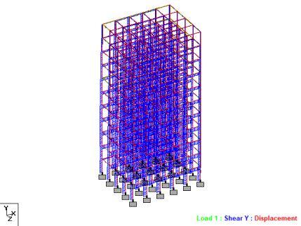
6.3 Analysis of Building
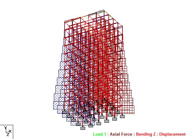
6.3.1 axial force:
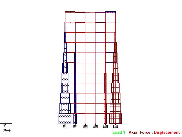

International Research Journal of Engineering and Technology (IRJET) e-ISSN: 2395-0056
Volume: 12 Issue: 01 | Jan 2025 www.irjet.net p-ISSN: 2395-0072 © 2025, IRJET | Impact Factor value: 8.315 | ISO 9001:2008 Certified Journal | Page238


International Research Journal of Engineering and Technology (IRJET) e-ISSN: 2395-0056
Volume: 12 Issue: 01 | Jan 2025 www.irjet.net p-ISSN: 2395-0072 © 2025, IRJET | Impact Factor value: 8.315 | ISO 9001:2008 Certified Journal | Page239

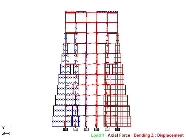
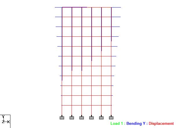
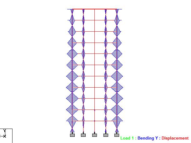
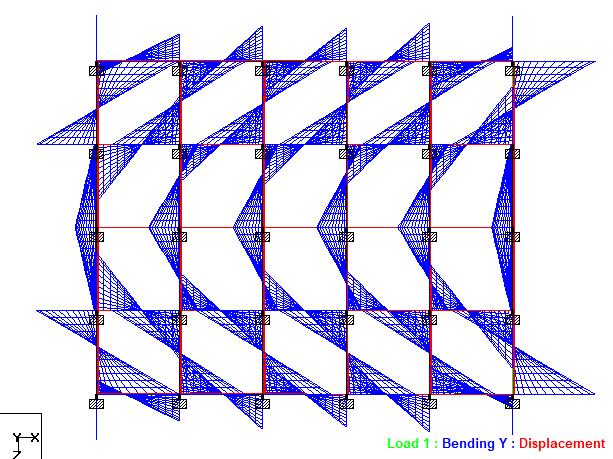
6.3.3 Bending Moment:


International Research Journal of Engineering and Technology (IRJET) e-ISSN: 2395-0056
Volume: 12 Issue: 01 | Jan 2025 www.irjet.net p-ISSN: 2395-0072

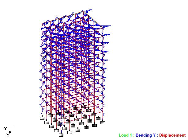

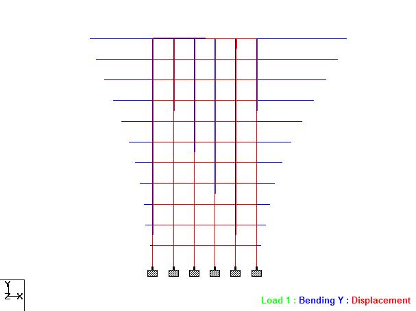

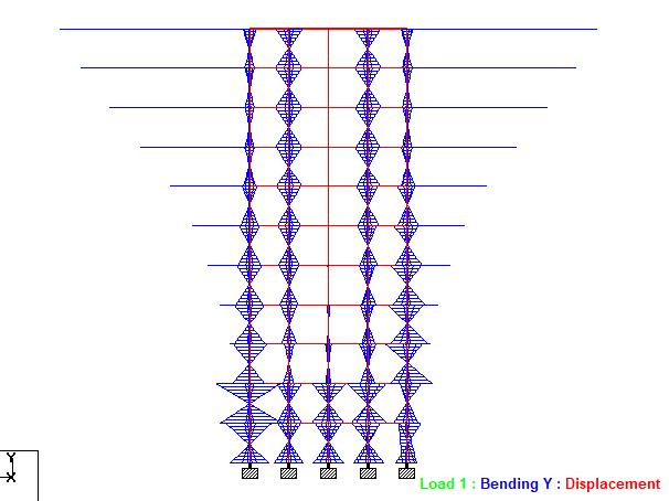

|
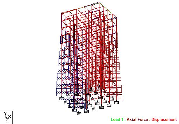
International Research Journal of Engineering and Technology (IRJET) e-ISSN: 2395-0056
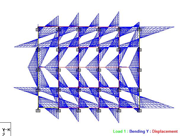
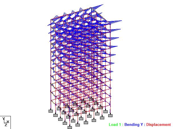
And(d)3d View
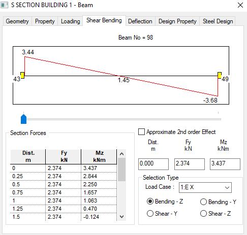
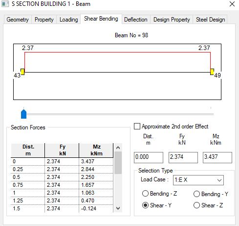
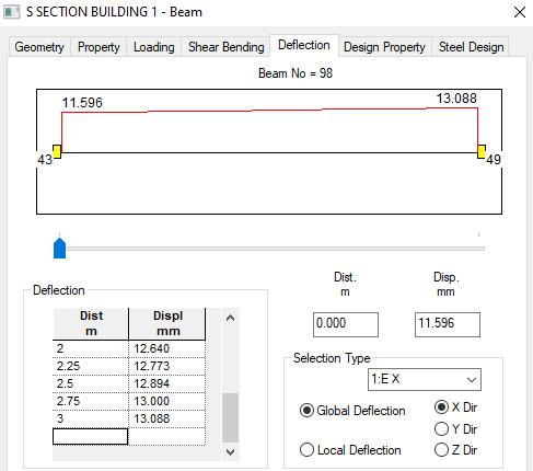
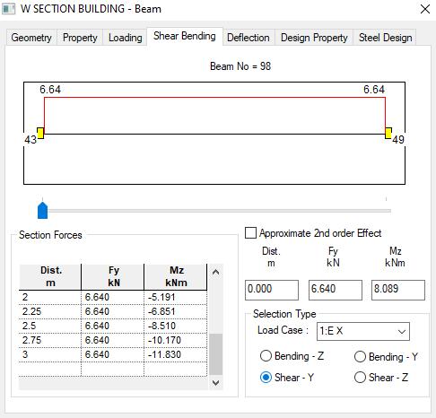
6.3.4 Shear, Bending Moment, and Deflection of a Beam:
BeamNo.98:
Volume: 12 Issue: 01 | Jan 2025 www.irjet.net p-ISSN: 2395-0072 © 2025, IRJET | Impact Factor value: 8.315 | ISO 9001:2008 Certified
International Research Journal of Engineering and Technology (IRJET) e-ISSN: 2395-0056
Volume: 12 Issue: 01 | Jan 2025 www.irjet.net p-ISSN: 2395-0072
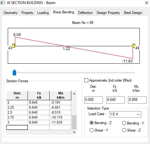
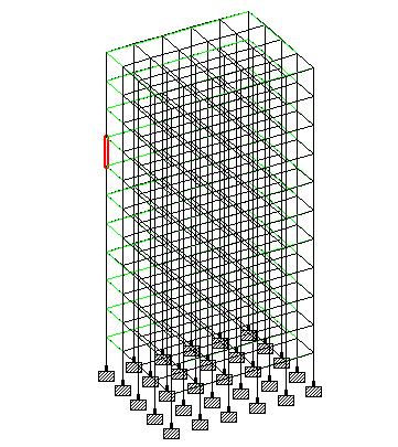
BendingMomentofABeamOfW-Section Building
2025, IRJET | Impact Factor value: 8.315 | ISO 9001:2008 Certified Journal | Page242
International Research Journal of Engineering and Technology (IRJET) e-ISSN: 2395-0056
Volume: 12 Issue: 01 | Jan 2025 www.irjet.net p-ISSN: 2395-0072
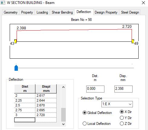
Figure 6.12 DeflectionofABeamOfW-SectionBuilding
7. RESULT AND DISCUSSION
For both W-Section and S-Section Steel Frame Buildings: displacements, Shear forces, and bending moments were calculatedandtheyaretabulatedbelow:
7.1 Node Displacement
7.1.1 Maximum Node Displacement:
MaximumNodeDisplacement
Table 7.1 MaximumNodeDisplacement
Graph 7.1 MaximumNodeDisplacement
From the above graph of Maximum Node Displacement, it can be observed that W–section steel structure shows less displacement values when compared to S-section steel structuresinalldirection.LesserNodeDisplacementshows higherStability.
7.1.2 Minimum Node Displacement:
MinimumNodeDisplacement
All values are negative and it indicates the downward direction
Table 7.2 MinimumNodeDisplacement
(in mm)
(in mm)
Graph 7.2 MinimumNodeDisplacement
GraphofMinimumNodeDisplacementshowsthat W–section steel structure show less displacement values when compared to S-section steel structures in all direction. If Node Displacement value is less then it gives higherStability.
Also, it can be concluded that from displacement point ofview S-sectionsteel structuresare notsuitable in high rise construction of building and if used special displacementcontrolsmeasureshouldbefollowed.
International Research Journal of Engineering and Technology (IRJET) e-ISSN: 2395-0056
Volume: 12 Issue: 01 | Jan 2025 www.irjet.net
7.1.3 Maximum Rotational Node Displacement:
Table 7.3 MaximumRotationalNodeDisplacement
MaximumRotationalNodeDisplacement
Parameter S-Section (inrad) W-Section (inrad)
MaxrX 0.008 0.001
MaxrY 0.001 0.000
MaxrZ 0.000 0.000
S-Section (in rad) W-Section (in rad)
Graph 7.3 MaximumRotationalNodeDisplacement
From the above graph of Maximum Rotational Node Displacement, it can be observed that W–section steel structure shows less rotational displacement values when compared to S-section steel structures in all direction. Lesser Rotational Node Displacement shows higherStability.
7.1.4 Minimum Rotational Node Displacement:
MinimumRotationalNodeDisplacement
Graph 7.4 MinimumRotationalNodeDisplacement
GraphofMinimumRotationalNodeDisplacement shows that W–section steel structure show less displacement values when compared to S-section steel structuresinalldirection.IfRotationalNodeDisplacement valueislessthenitgiveshigherStability.
7.2.1 Maximum Axial Forces and Shear Forces:
MaximumAxialForcesandShearForces
Table 7.5 MaximumAxialForcesandShearForces
All values are in negative and it indicates the
Table 7.4 MinimumRotationalNodeDisplacement
Graph 7.5 MaximumAxialForcesandShearForces
Graph of maximum axial forces and shear forces shows that there is no considerable difference in magnitudeofforcesin XdirectionandZdirection buthas significant change in Y direction. W-Section has high horizontal values but have lower values on in Y direction. InW-Section,ShearForcevalueislesswhencompared to
International Research Journal of Engineering and Technology (IRJET) e-ISSN: 2395-0056
Volume: 12 Issue: 01 | Jan 2025 www.irjet.net p-ISSN: 2395-0072
S-Section. For higher stability of structure, shear force shouldbeless.
7.2.2 Minimum Axial Forces and Shear Forces:
MinimumAxialForcesandShearForces
All values are in negative and it indicatesthedownwarddirection
Table7.6 Minimum Axial Forces and Shear Forces
Graph 7.7 MaximumBendingMoment
Graph of Maximum bending moment shows that S-section steel structure show less bending moment valueswhencomparedtoW-sectionsteelstructuresinall direction. If bending moment value is less then it gives higherStability.
7.2.4 Minimum Bending Moment:
MinimumBendingMoment
Graph 7.6 MinimumAxialForcesandShearForces
From the above graph of minimum axial forces and shear forces, it can be observed that S–section steel structure shows less axial forces and shear forces values when compared to W-section steel structures in all direction. Lesser axial forces and shear forces shows higherStability.
7.2.3 Maximum Bending Moment:
MaximumBendingMoment
Table 7.7 MaximumBendingMoment
Allvaluesareinnegativeanditindicatesthedownward direction
Table 7.8 MinimumBendingMoment
Graph 7.8 MinimumBendingMoment
From the above graph of minimum bending moment, it can be observed that S–section steel structure showslessbendingmoment valueswhencomparedtoWsection steel structures in all direction. Lesser bending momentshowshigherStability.
Volume: 12 Issue: 01 | Jan 2025 www.irjet.net
7
Fromthegraph,weobservedthatthestoreydrift are more in S-section steel structure as compare Wsection structure. Storey drift more varies at each floor in S-section structure in zone 2. The storey drift values are not more fluctuating in W-section. It concludes that Wsectionismorepreferableaccordingtostoreydrift.
8.CONCLUSION
Node displacements are very less for W-section steel structure when compared to S-section in all direction.
It can be concluded that from displacement point of view S-section steel structures are not suitable in high rise construction of building and if used special displacement controls measure should be followed.
Shear forces and axial forces are very less for Ssection steel structure when compared to WsectionsteelstructureinalldirectionexceptinYdirection.ThevalueofmaximumshearforceinYdirection of S-section structureis 14.84% greater thanW-sectionstructure.
BendingmomentsareverylessforS-sectionsteel structure when compared to W-section steel structureinalldirection.
According to axial forces, shear forces and bending moment, S-section steel structure is betterthanW-sectionsteelstructure.
The storey drift values are high in S-section steel structureascomparetoW-sectionstructure.
StoreydriftaremorefluctuatingateachfloorinSsection steel structure in zone II compare to Wsectionsteelstructure.
It concludes that W-section is more preferable basedonstoreydriftvalues.
Result shows that W-section steel structures in G+10 building gives less storey drift and displacement which helps to reduce intensity of lateral earthquake forces. So, W-section steel structures should be used in case of buildings in low as well as high risk zones under dynamic loading
1. V. M. Sounthararajan, S. Sivasankar, R. Vinodh Kumar, Nabajyoti Modak(2019),”Significant Effect on the Mortar Studies Containing various Supplementary Cementations Materials to act as Green Building Materials”, journal of Green Engineering,Vol.9,no.3,pp.360-370.
2. ShrikantM.Harle(2017) “AnalysisbyStaad-pro and design of structural elements by MATLAB”, JournalofAsianScientificResearchvol-7pp.145164.
3. Er.eev Kumar, Brahmjeet Singh, Er. Bhupinder Singh (2016) “Optimization of Roof Truss Using STAAD PRO V8i”, International Journal of Recent ResearchAspectsvol-3pp.86-90.
4. K Venu manikanta, Dr. Dumpa Venkateswarlu (2016) “Comparativestudy ondesign resultsofa multi-storied building using Staad Pro and Etabs for regular and irregular plan configuration”, International Journal of Research Sciences and AdvancedEngineeringvol-2pp204-215.
5. Tejashree Kulkarni, Sachin Kulkarni, Anjum Algur, M. H. Kolhar (2016) “Analysis and design of high rise building frame using Staad Pro”, International Journal of Research in Engineering andTechnologyvol-5pp235-237.
6. Ankita Rode, Dr P. Y. Pawade (2016) “Comparative Study of Seismic Behavior of Honeycomb Structure with Conventional
International Research Journal of Engineering and Technology (IRJET) e-ISSN: 2395-0056
Volume: 12 Issue: 01 | Jan 2025 www.irjet.net p-ISSN: 2395-0072
Structure by using Staad Pro”, International Journal of Science Technology & Engineering Vol2pp.108-112.
7. Salem R.S Ghdoura, Vikas Srivastava (2016) “Analysis of Steel Framed Structure using STAAD Pro and ROBOT Software”, International Journal ofScientificEngineeringandTechnologyVol-5pp 1442-1449.
8. Heera Lal Bhardwaj,Ajit, Yogesh Kaushik (2015) “Analysis and Design of Four Leg Steel Transmission Tower using Staad. Pro”, International Journal of Advanced Engineering, ManagementandSciencevol-1pp.7-13.
9. Riya Dey, Sagnik Sen Sarma, Abhirup Bhattacharjee (2015) “Wind and Earthquake effect on R.C.C & Steel Structure”, International Journal ofCivil Engineering andTechnologyvol-6 pp.43-52.
10. D V Swathi (2014) “Design and analysis of preengineered steel frame”, International Journal of ResearchSciencesandAdvancedEngineeringvol2pp250-255.
11. BijanSamali,UlrikeDackermannandJianchun Li(2012) “Location and Severity Identification of Notch-Type Damage in a Two-Storey Steel Framed Structure Utilising Frequency Response Functions and Artificial Neural Network”, Advances in Structural Engineering Vol. 15 pp 743-757.
12. X.H. Dai, Y.C. Wang, C.G. Bailey (2010) “Numerical modelling of structural fire behaviour ofrestrainedsteelbeam-columnassembliesusing typicaljointtypes”,EngineeringStructuresVol-32 pp2337-2351
13. Sang-Wook Bae, Roger A. LaBoube, Abdeldjelil Belarbi, Ashraf Ayoub (2008) “Progressive collapse of cold-formed steel framed structures”, Thin-WalledStructuresVol-46pp706–719.
14. Mar´ıa Bel´ en Prendes Gero, Antonio Bello Garc´ıa, Juan Jos´ edelCozD´ıaz (2006) “Design optimization of 3D steel structures: Genetic algorithms vs. classical techniques”, Journal of Constructional Steel Research vol-62 pp 1303–1309.
15. IS: 1893(Part-1) -2002, “Criteria for Earthquake Resistant Design of Structure, Part -1 General ProvisionsandBuilding”,Fifthrevision,Bureauof IndianStandards,NewDelhi.
16. IS: 875 (Part 1), “Code of practice for Design Loads (other than Earthquake) for buildings and structures Part 1 Dead Loads – Unit Weight of building materials and stored material”, second revision,BureauofIndianStandards,NewDelhi.
17. IS: 875(Part 2)-1987, “Code of Practice for Design Loads ( other than Earthquake) for buildings and structures Part 2 Imposed Loads”,
Secondrevision,BureauofIndianStandards,New Delhi.
18. IS: 875(Part 3)-1987, “Code of Practice for Design Loads (other than Earthquake) for buildings and structures, Part 3 Wind Loads”, Secondrevision,BureauofIndianStandards,New Delhi.