1
International Research Journal of Engineering and Technology (IRJET) e-ISSN: 2395-0056

Volume: 09 Issue: 08 | Aug 2022 www.irjet.net p-ISSN: 2395-0072

1
International Research Journal of Engineering and Technology (IRJET) e-ISSN: 2395-0056
Volume: 09 Issue: 08 | Aug 2022 www.irjet.net p-ISSN: 2395-0072
Abstract- Twisted pipes are classified on the base of curve as constant curve and variable curve pipes. The former are called as “helices” i.e. spiral coil & the ultimate as ‘ spirals ”. When a fluid flows in a helically curled tube centrifugal forces causes secondary fluid stir, which gives rise to increase heat transfer rate. At veritably short distances from the launch of heat transfer zone, the thermal boundary subcaste is too thin to be affected by the secondary inflow field, which reaches its maximum intensity at some distance down from the tube wall. thus, near the tube inlet the rate of heat transfer measure in a curled tube to that in a straight tube varies only as NDe1/6 and Coil tube offers little advantage over a straight tube. The present work involves fabrication of a setup for spiral coil of ID8.04 mm & OD9.70 mm and 3800 mm length. The coil consists of a tank of ID 305 mm with a bath result like water. The face temperature of spiral coil at different positions, bath temperature are measured on digital temperature archivist. The water bay and outlet temperature are measured by thermometer. The work involves analysis of heat transfer between bath result and water flowing through the spiral coil. The convective heat transfer will be anatomized for with and without agitation. The ideal of this discussion work is to gain a better and further quantitative sapience into the heat transfer process that occurs when a fluid flows in a spiral coils tube.
Keywords Heat Transfer1, Helical coil2, copper Coil 3
Spiral coils are compact in size and provides distinct benefit like advanced film measure, more effective application of available pressure drop, which results in effective and less precious design. spiral coil permits running of high temperature and extreme temperature differentials without highconvincedstressesor expensive expansionjoints.spiralcoiloffersadvantagesoverstraight tubesduetotheirconcisenessandincreasedheattransfer measure. The increased heat transfer portions are a consequence of the curve of the coil, which induces centrifugalforcestoactonthemovingfluid,performingin secondaryinflow.AFlowthroughHelicalCoilWhenafluid flowsthrougha straighttubethehasteismaximumatthe
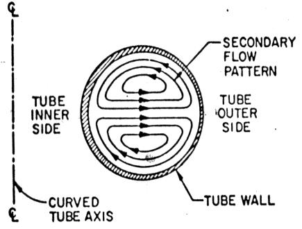
tube centre, zero at the tube wall and symmetrically distributedabouttheaxis.still whena fluidflowsthrough atwistedtube,theprimaryhasteprofileshownin Fig-1.1 is distorted by the addition of secondary inflow pattern. The secondary inflow is generated by the centrifugal actionandactsintheAeroplan
verticaltotheprimaryinflow.Sincethehasteismaximum atthetubecentrethefluidatthecentreissubordinatedto maximum centrifugal action, which pushes the fluid towardsexternalwall.Thefluidattheexternalwallmoves inward along the tube wall to replace the fluid ejected outwards. This results in the conformation of two maelstroms symmetrically about a vertical aeroplane throughthetubecenter
1.2.1 Heat Transfer in Helical coil: - The heat and mass transfer are advanced in a twisted pipe than in an original straight tube at the same inflow rate, due to actualityofsuperimposedsecondaryinflow(5).
Flow in twisted path is a complex miracle because of the presenceofcentrifugalforcesactingonrudimentsofliquid flowing through similar pipes. To balance this centrifugal force, a pressure grade across the pipe is formed. The pressureismaximumatexternalwallandminimumatthe innerwall.Thisresultsinasecondaryinflow,inwhichthe fluid near the top and nethermost moves inward and the fluid in the middle moves outward. The secondary inflow isthecauseofhighheattransferratesanddisunionlosses inapipe.
International Research Journal of Engineering and Technology (IRJET) e-ISSN: 2395-0056
Volume: 09 Issue: 08 | Aug 2022 www.irjet.net p-ISSN: 2395-0072
operation of Helical Coil- Helical coils are considerably employed for heat transfer operation in the process and powerdiligence.
Someoftheoperationsarelistedas
1. spiral coils are used for transferring heat in a chemical reactor andagitated vessel becauseheattransfer portions are advanced in spiral coils. This is especially important when chemical reactors having high heat of response are carried out and the heat generated( or consumed) has to be transferred fleetly to maintain the temperature of the response. Also because of spiral coils have a compact configurationfurtherheattransferfacecanbehandedper unitsofspacethanbyuseofstraighttube.
2. Due to conciseness, it's used for brume generation in marineandartificialoperation.
3. The actuality of tone- convinced acceleration field in spiral coil makes spiral coil most desirable for heat transfer and fluid inflow operation in the absence of a gravenessfield,similarasforspaceshipsinexternalspace.
4. spiral coils have lately being studied for possible operation inbio-engineering. Weissman and Mockero’s lately studied the use of spiral coils to compound mass transfer in membrane blood- oxygenerators. Their study demonstrated, both theoretically and experimentally that by curling a membrane tube into a spiral coil, they could mainly increase the mass transfer rate of oxygen and carbon dioxide to and from the blood flowing inside the tube.
5.spiralcoilshavebeenconsiderablyusedinthecryogenic assiduityfortheliquefactionoffeasts.Thesinglepressure mixed refrigerant (SPMR) process for the liquefaction of the natural gas is a current illustration. Recent emphasis ontheincreasedproductofthawednaturalgaswillcallfor anincreaseduseofcurledtubeheatexchangers.
1.3 Scope of Work: -Helical coils are widely used in all fields of engineering, so a thought is given to experimentally suggest the values of heat transfer coefficients, the various numbers associated with heat transfer phenomenon and suggest a fluid which gives maximumoverallheattransfercoefficient.
The dissertation consists of selection and fabrication of various components required for the experimental analysis of flow inside a helical coil. The setup for the analysis consists of copper helical coils of inner diameter 8.04mmandlength3800 mm.Thesetuprequireda tank
or vessel of internal diameter as 30.5 cm to accommodate thehelical coilalongwitha heating elementof1500 watt. Theworkinvolvestheanalysisofresultsobtainedforfluid like water. The work carried out for the both with and withoutagitationconditionforallfluids.
2.1 Introduction: The convective analysis of helical coil, requires the experimental set up to record various temperaturealongthelengthofcoilatdifferentheatinput and at different mass flow rate. The setup requires fabrication & selection of different component for the analysispurpose.
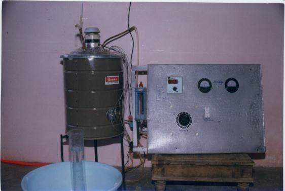
2.2 Experimental setup :
Fig - 2.1 Shows the schematic arrangement of the various componentsrequiredfortheexperimentation.
1. Fill the cylindrical tank with water such that the entiresetupofhelicalcoilimmersedinliquid
2. Adjust the heat supplied to setup by properly adjusting dimmer. Heat input should be recorded fromthevaluesofvoltageandcurrent.
3. Adjust the flow rate of water entering in helical coil in a way to maintain constant flow rate after enoughheatingofliquid.
4. Notedownthevariousthermocouplereadingwith thehelpoftemperatureindicatoratsteadystate.
5. Carry out the experimentation for the various values of heat input and by changing the mass flowrate.
2.3 Component used: The list of components along with material & specification for experimentation is given in tableno.3.1
Table 3.1 : Differentcomponentusedfortheexperimental setup.
Sr. No. Name of component Material Specification
1. Helicalcoil Copper ID8.04mm, OD9.70mm & length 380cm
2. Cylindrical GIsheet ID30.5cm
International Research Journal of Engineering and Technology (IRJET) e-ISSN: 2395-0056
Volume: 09 Issue: 08 | Aug 2022 www.irjet.net p-ISSN: 2395-0072
Height41Cm Wall thickness 25 mm
3. Thermo couple and digital temperature indicator
A digital temperature indicator with 6 point selector switch and thermo couple wire &junction.
4 Dimmerstat 6 Amp Dimmer stat with a range of0-230Volt
5 Stirrer ¼ HP cooler motor pump of RPM 1360, amp 0.36, 50 Hz and 45 watt.
6. Flow measuring Device
Glass A glass biker of 1 liter marking
7 Heatingcoil Copper 1500-watt drum heating coil
The various thermocouples mounted along the length of coil are worked as per the distance specified and are enlistedintableno.2.1
2.4 Criteria for selection of component:
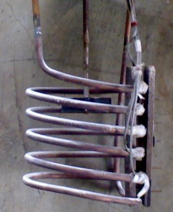
2.4.1 Helical Coil: Thematerialselectionforthespiralcoil is similar that, it must have high thermal conductivity. At thesametimematerialshouldbeeasytobendintheform ofspiralstructure,sothematerialnamedforthespiralcoil which has both these parcels & it's fluently available. The dimensionofspiralcoillike innerdia.&lengtharenamed grounded on the vacuity of material and at the same time to accommodate the number of thermocouples along the length.Toachieveproperheattransferfiveturnsofspiral coilsofbobbymaterialisnamedgroundedonlengthofcoil asshowniffig.3.2
Fig - 3.2 Helicalcoil
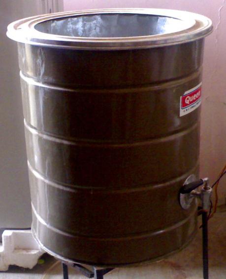
2.4.2 Cylindrical Tank: The criteria for selection of spherical tank should be similar that, the spiral coil arrangement, the heater and stirrer for agitation must accommodateinit.Consideringthepropersizes,height of coil & the distance of spiral coil from the heater, a spherical tank of dimensions30.5 cm inner periphery, height41.0 cm with a consistence of 25 mm is named as shown in fig3.3. The tank named is of material GI & is the same used for water heater purpose in the home operation.
Fig - 3.3 Cylindricaltank
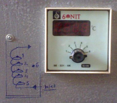
2.4.3 Thermocouple and Digital Temperature Indicator To record the colorful temperature of water insidethecoilatcolorfuldistances5Cr-Althermocouples
International Research Journal of Engineering and Technology (IRJET) e-ISSN: 2395-0056
Volume: 09 Issue: 08 | Aug 2022 www.irjet.net p-ISSN: 2395-0072
are named. To record the temperature, a digital temperatureindexasshowninfig3.4.,ofleastcount0.10c andtherangeof0-5000Cisnamed.
Fig - 3.4 Digitaltemperatureindicator
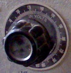
2.4.4 Dimmerstat: A dimmerstat of range( 0- 1500 W) is named tofulfill thedemand ofvaryingheatinputtoassay theperformanceofheattransferbetweenwater&colorful resultasshowninfig3.5..
2.5 Testing procedure: The convective heat transfer analysis of spiral coil is principally heat transfer between thebathliquid&fluidflowingthroughspiralcoili.e.water. Thebathliquidusedfortheanalysispurposearewater.To find out the colorful parameters needed for the analysis certain procedure must be espoused. So a testing procedure is designed and the same as followed during thistrial.
To avoid any leakages, originally a leak test of the experimental setup is assured at outside inflow rate of fluid.Thetestingprocedureislistedasfollows.
1.Fillthesphericaltankwithproperliquid(viz.watersuch thattheentiresetupofspiralcoilimmersedinliquid.
2.Acclimatetheheatsuppliedtosetupbydulyconforming dimmer.Heatinputshouldberecordedfromthevaluesof voltageandcurrent.
3.Acclimatetheinflowrateofwaterenteringinspiralcoil in a way to maintain constant inflow rate after enough heatingofliquid.
4. Note down the colorful thermocouple reading with the helpoftemperatureindexatsteadystate.
5. Carry out the trial for the colorful values of heat input andbychangingthemassinflowrate.
2.4.5 Stirrer: For proper mixing of various solution & to increasetheturbuanceastirrerisrequired.Inthissetup,a ¼HPcoolermotorpumpof1360rpmisusedasstirrer.
2.4.6 Flow Measuring Device: Tomeasurethequantityof water flowing through the helical coil, a 1 lit glass measuringjarisused.
2.4.7 Heating Coil: A1500-wattdrumheatingcoilisused toheatthebathsolutioninthetank.
1.
The colorful instruments used for testing purpose are as follows
1.Ammeter(0–10A)
2.Voltmeter(0-230V)
3.Thermocouple
International Research Journal of Engineering and Technology (IRJET) e-ISSN: 2395-0056
Volume: 09 Issue: 08 | Aug 2022 www.irjet.net p-ISSN: 2395-0072
4. Measuring jar and stop watch( due to attainability of Rotameter)
5.Tachometer
The measure readings recorded in table 3.3 - 3.8 are used for calculation of heat transfer coefficient, over all heat transfercoefficient,theconvective analysisgoverned with various non dimensional numbers and Nusselt number correlation. Depending upon the flow conditions the analysis requires numbers like Re number, Nusselt number,Prnumber,Denumber..
3.2.1 Calculation for Deciding Type of Flow : In helical coil flow of fluid is a function of Reynold number and Prandtlnumber.
For deciding laminar and turbulent flow following equationareused(3),
Forlaminarflow
Forturbulentflow,
Sample calculation for water at head input 0.6 kw and massflowrateof5.75gm/sec,
Pr=4.92>1& Re=0.621>0.4
Flowisturbulent
3.2.2
Heat transfer coefficient in helical coil is calculated by using equation are used (3), Sample calculation for water at heat input Qi = 0.6 kw and mass flow rate of 5.75 gm/sec,
Fromequation4.5, Pr=4.92 Re=1170
di =8.04mm De=259
Nu=13.74
Nu=
Where,k=0.626W/m20k=Thermalconductivitywhichis taken from thermo physical properties of water at 34.50c (22)
hi=1.069Kw/m20k
3.2.3 Calculation for Over All Heat Transfer Coefficient :
Theoverallheattransfercoefficientiscalculatedbyusing therelationstatedasper(3)byequation
Where, U –Overallheattransfercoefficient
Q –Heatflowrate
A –Areaofthehelicalcoilatoutside
Tb –Bathtemperature
Tm –Meantemperatureofthehelicalcoil
Sample calculation for water at head input 0.6 kw and massflowrateof5.75gm/sec, Appendix A-D shows the calculated values of Re number, Nu number, hi, and U for water for without agitation and withagitationatadifferentconcentration.
Toanalysestheconvectiveheattransfermiracleinaspiral coilfluidslikewaterisusedduringthetrial.Waterisused as a fluid flowing through spiral coil whereas fluid stated above are allowed to compass the entire spiral coil. Groundedonthetrialthenumberofparametersisstudied. On the base of below results and discussion following conclusionaredrawn.
International Research Journal of Engineering and Technology (IRJET) e-ISSN: 2395-0056
Volume: 09 Issue: 08 | Aug 2022 www.irjet.net p-ISSN: 2395-0072
[1] C.F.C. Rogers and Y.R. Mayhew “Heat Transfer and Pressure Loss in Helically Coiled Tubes With TurbulentFlow”,Int. Journal ofHeatMassTransfer, Vol–7PP1207-1216,1964.
[2] VenugopalKabairandN.R.Kuloor“HeatTransferto NewtonianFluidsinCoiledPipeinaLaminarFlow”, Inst.Journal HeatandMassTransferVol – 9,PP6975,1966
[3] YasuoMoriandWataruNakayama “StudyofForced Convective Heat Transfer in Curved Pipes”, Inst. JournalHeatMmasstransferVol –10PP681–695, 1967.
[4] R. A. Seban and E.F. Mcloughlin “Heat Transfer In Tube Coils With Laminar And Turbulent Flow” Inst. J.HeatmasstransferVol–6pp387-395,1963.
[5] A. N. Dravid, K. A. Smith, E. W. Merill and P. L. T. Brain “Effect Of Secondary Fluid On Laminar Flow Heat Transfer In A Helically Coiled Tubes” Al. ChemicalEngineJournalVol17,No5pp1114-1122 sept.1971.
[6] C.E. Kalb and J. D. Seadar, “Heat And Mass Transfer Phenomina For Vis Cous Flow In Curved Circular Tubes” Inst. J. Heat Mass transfer Vol 15, pp 801817,1972.
[7] S. Raja Sekaran, V. G. Kabair and N. R. Kuloor, “Secondary Flow Of Non – Newtanian Fluids In Helical Coils” Indian Journal of Technology, vol 4, Feb–1966.
[8] G.S.Arvind,Y.Aran,R.SunderandS.Subrahmaniyan “Natural Convective Heat Transfer in Helically Coiled Heat Exchange” Vol 84, sept. 2003, I.E. (I) Journal
[9] V.V. Sitram Murthy and R. C. Sastrey “Laminar Convective Heat Transfer And Viscous And Non Newtonian Liquids In Helically Coiled Tube” Indian Chemical Engineer Section A, Vol 42, No. 1. Jan –March2000
[10] A. Ramasubramanian and S.K. Pandey “Agitation And Heat Transfer Studies In Suspension TransactionOfASME,Vol117,Feb1995.
[11] R.K. Prabhudesai and Shah “ Heat Transfer Though HelicalCoils”tractionofI.I.Ch.E.Vol.XII,1959-60.
[12] S. Manafzadeh, H.A. Simon and JCF chow “Heat Transfer Enhancement In Coiled Tubes” letters in heatandmasstransfer,Vol–9PP479-435,1982.
[13] S.N. Gupta and P. Mishra “Isothermal Laminar Flow of Non Newtonian Fluids Though Helical Coils” Indian Journal of technology, Vol 13, June 1975 PP 245-250.
[14] Venugopal Kabair and N.R. Kuloor “Comparision Of Performance Of Helical And Spiral Coil Heat Exchange” and “Secondary Flow Of Non Newtonan FluidsInHelical Coils”IndianJournal oftechnology, Vol4Feb1966.
[15] D.G. Prabhajan, G.S. Paghavan and T.J. Renie “Comparison of Heat Transfer Rates Between A Straight Tube Heat Exchange And Helically Coiled HeatExchange”
[16] E.Demaerteleire“HeatTransfer toAHelical CoilIn Mechanically Agitauted Gas Ligit Dispersaion” chemicalengg.ScienceVol33PP107-1113.1978
[17] Shashi Krishna Pandey “Heat Transfer Studies For Agitated Liquits” CEW Vol XIII No. 9 Page 47-50, sept1978.
[18] Wang Kai and Yu shengyao, “Heat Transfer And Power Consumption Of Non – Newtanian Fluids In AgitatedVessels”,Chemical engineeringscience,Vol 44,No1,PP33-40,1989.
[19] S. Rajasekharan, V.G. Kubair and N. R. Kuloor “Heat TransferToNonNewtonianFluidsInCoiledPipesIn LaminarFlow”Int.Journalofheatandmasstransfer Vol13PP1583-1594,1970.
[20] A.V. Kirpikov, “Heat Transfer In Helically Coiled Pipes,” Trudi moskov, first ktim, Moshinojtrojenija 12,43-56(1957)
[21] James R. Lines ‘Hellically Coiler Heat Exchanges OfferAdvantagesPetroleumEnginner,April1952.
[22] S. Domkundwar, “Heat Transfer Data Book” DhampatRai publicationNewDelhi.
[23] B.T. Najaguna, “Thermal Science Data Book”, Tata MaGraw-HillCo.Ltd.,NewDelhi.