International Research Journal of Engineering and Technology (IRJET) e-ISSN: 2395-0056

Volume: 09 Issue: 06 | June 2022 www.irjet.net p-ISSN: 2395-0072

International Research Journal of Engineering and Technology (IRJET) e-ISSN: 2395-0056

Volume: 09 Issue: 06 | June 2022 www.irjet.net p-ISSN: 2395-0072
1Doctor at Mechatronics, engineering, Canadian international college, Cairo, Egypt 2,3,4,5,6,7Students at Mechatronics, engineering, Canadian international college, Cairo, Egypt
Abstract This project presents an active ball joint mechanism. Robots mainly consist of links and joints, hence studying different joints and coming up with new joints will contribute to advancing robots. The methodology used in this project is; Proofing the concept of the Omni Joint by theoretical analysis and manufacturing a prototype, comparing the following revolute joints; Omni Joints, Hook’s joint, and Ordinary joint. The comparison is regarding; points of singularity, range of field of motion, inverse kinematics, and applying it on different paths using MATLAB and studying the stresses on the mechanism, and design using SolidWorks software in different postures.
The experimentally results of the innovative gears are to create mechanism with three RDOF The challenge in multi degree of freedom mechanisms is the range of motion. In this mechanism there is two types of placing the two driving modules. First of them is opposite type 180[deg]. It provides a range of motion of 270, 90, 360 [deg]. The second one is perpendicular type 90 [deg] this range of motion is relatively high compared to other.
Keywords: ball joint mechanism, SolidWorks, MATLAB, sphericalgear.
Variouskindsofmechanismshavebeenusedasajoint whichhasbeenappliednotonlytotheindustrybutalsoto robotsormanipulators.sincethesemechanismshaveonly one or two degrees of freedom if these are applied to complexmechanismssuchaswristjoint,endeffectorrobot arms,andvariousothermechanismsitneedsmulti degree of freedom, the structure gets complicated due to many links, gears, complex design, and reliability become lower. The classical mechanisms which use a friction wheel for force transmission comprise a sphere and another frictional wheel, but they faced many problems like slippage which affect high torque transmission and positioningaccuracy.There isanotheractuator,whichisa three dimensional extension of the induction motor has been proposed. Although it has high power capability, it still has problems with power consumption, friction, and eddy currents which leads to high temperature. to solve these problems, we developed a multi degree of freedom mechanism for multiple applications this mechanism has threerotational degreesoffreedombased on nonslipgear
meshing, the mechanism provides high torque transmission and reliable positioning without requiring a three dimensional sensor. In addition, because the actuator and output link can be flexibly arranged, the mechanism can take various configurations. Although the proposed gears have complex shapes, we believe that recent advances in manufacturing technology will enable theirpracticalfabrication.Inoptimizedfuturedesigns,the mechanism will gather the joints of a robot or other mechanisms at one point, reducing the energy and resource consumption and improving the economy of robotoperation.
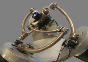
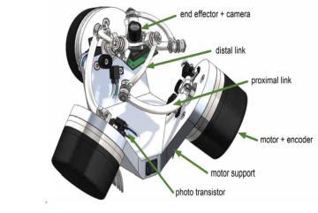
The Agile Eye is a spherical parallel manipulator capable of orienting a camera or a laser pointer with high speedandaccuracyinthreerotationaldegreesoffreedom for vision applications, The prototype was built in 1993 and has been gaining in popularity ever since. The workspaceoftheAgileEyeissuperiortothatofthehuman eye.Theminiaturecameraattachedtotheend effectorcan bepointedinaconeofvisionof140°with±30°intorsion. Moreover,duetoitslowinertiaanditsinherentstiffness,
Thismechanismhastwomainadvantageswhichare:
itcanachieveangularvelocitiesabove1000°/sec
it can achieve angular accelerations greater than 20000°/sec2 Whichisbeyondthecapabilitiesofthehumaneye.
Fig.1(a),(b)AgileEye
Volume: 09 Issue: 06 | June 2022 www.irjet.net p ISSN: 2395 0072

Ithassomedisadvantageswhichare:
low range of motion compared to active ball joint mechanism
cantransferlowtorqueonly
B. Atlas Spherical orienting device using Omni Wheels [2]
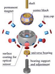
Its orienting concept uses Omni wheels to actuate the threerotationalDOFmotions(roll,pitch,andyaw).
The traditional system for force transmission, which depends on friction, comprises a sphere and several strategicallyplacedfrictionwheels.
The mechanical design of a spherical induction motoriscomplex
Complicatedthree phasewindings
Eddycurrentlosses
Heatgeneration
D. Spherical Wheel Motor (SWM) [4]
spherical motors where design focuses have been on controlling the three degrees of freedom (DOF) angular displacements with high position accuracy and these are theonlytwoadvantagestheSWMoffersameanstocontrol theorientationofacontinuouslyrotatingshaftinanopen loop (OL) fashion The concept feasibility of an OL controlledSWMhasbeenexperimentallydemonstratedon aprototypethathas8rotorpermanent magnet(PM)pole pairsand10statorelectromagnet(EM)pole pairs.
This mechanism solves all problem that face the previous project,sothemainadvantagesare:
providesthreerotationaldegreesoffreedom
reducestheslippage
provideahigh powertransmission. Butitstillhassomedisadvantages:
Itcannotsolvefrictionproblem
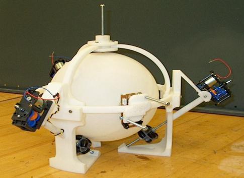
C. Spherical Stepper for Robotic Applications [3] stepper motor capable of three degrees of freedom (DOF) motion in a single joint. The most important advantagesarethat
The ball joint like motor has no singularities except at the boundary of the workspace and can perform isotropicmanipulationinallthreedirections.
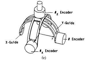
This(SWM)hasalotofdisadvantages:
complexdesign
limitationofworkingspacerange
lossesduetoeddycurrent
heatgeneration
lowtorque
highnon linearityofthetorque
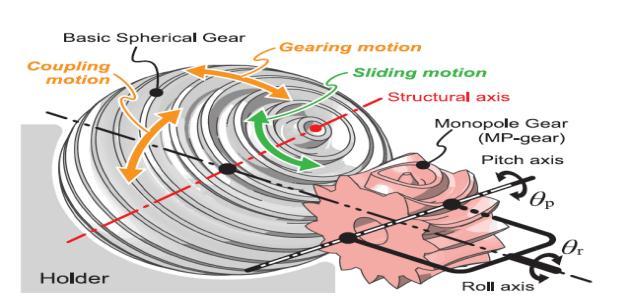
The main Object of the work is to understand work system of spherical gear, and creating a mechanism that has three rotational degrees of freedom without slippage andwithhighpositionaccuracyandlargerangeofmotion the design of spherical gear meshing. This mechanism can actively drive three DOF. During meshing, the two gear types interacted through gearing, coupling, and sliding motions, allowing a single MP gear to constrain or drive twoDOFoftheCS gear
After discussing the main characteristics of our project the designing issues mechanism contains many unique components,suchasCS gearandMP gear.Although these brought new possibilities, some difficulties are foreseen. Projectincluding:
Operational Issues of CS Gear, MP Gear, and Holder.
ManufacturingofMP GearandCS Gear
HolderandRangeofMotion.
A. Operational Issues of CS Gear, MP Gear, and Holder.
This section discusses the practical design and operational issues of CS gear, MP gear, and holder. Of the meshing between the CS gear and MP gear, the gearing motionhaspropertiessimilartothoseofnormalgear.The backlash between the MP gear and the CS gear in the prototype was 0.13 0.34 [deg] in terms of the CS gear angle, as shown in Since the MP gear drives the CS gear with a wide line contact, its transmission capacity is consideredto belarge, evenif there are someslotsin the CS gear,whichisexpectedduetotheothertoothstructure. The transmission efficiency is expected to be similar to a normal spur gear, and the forward and backward efficienciesshouldalwaysbesymmetrical.However,near polemeshingincreasesslidingcontact,sothetransmission efficiency will decrease due to friction. These need to be revealedmoreintermsofgearengineering.
The sliding motion is a sliding contact behavior that is strongly influenced by friction. Therefore, in practice, the toothsurfaceshouldbelubricatedwithgrease,evenifitis a resin, to reduce the contact friction with the holder. If there is an error of meshing due to backlash in coupling motion, i.e., an error between the CS gear and MP gear toothline,thenotchesintheCS gearmayconflictwiththe MP gear during the sliding motion. Chamfering to the corneroftheCS /MP gearteethwill reducethisproblem. Itisalsoimportanttokeepaproperbacklash.Thedistance between the MP gear and CS gear is provided by the holder and the driving module. The holder in the current design requires some mechanical compliance to allow for thermalexpansion,resinswelling,andfabricationerrorsto keeptheCS gearona spherical surface.Asmall preloadis applied to hold the CS gear in place and small variations occurdependingontheorientationoftheCS gear.Inother words ,the relative distance between the tooth tips of the CS gearandtheinnersurfaceoftheholderdoesnotideally fluctuate.Sincethedrivingmodulesinstalledintheholder also variate with the holder, the distance between the CS gear and the MP gear is kept constant. However, in practice, the variation of the relative distance may not be zero. This is a complex problem determined by the distribution of mechanical compliance of the holder, the mounting position of the driving module, the preload, and the amount of fabrication error. Adopting a typical ball joint design approach will contribute to a more appropriateholderdesign

EstablishingamanufacturingmethodforaCS gearand MP gear is one of the biggest challenges. 5 axis machining centers are a viable solution for both metallic and resin materials. On the other hand Using a 3D printer is a good way to fabricate, this mechanism. is an early prototype of thisprojectandMP gears,whichweremanufacturedby3D printer for theory validation and are confirmed to work. Also, the MP gear’s shape generation algorithm is already established and the module and number of teeth can be easilychanged.
In the case of metal 3D printers, a presence of a rough surface due to the sintering of the metal powder is not suitable for CS /MP gear. On the other hand, it is remarkable that combined machining centers and metal 3D printers have emerged in recent years. The problem may be solved by cutting only the tooth contact surface thininpost processing
TheCS gearofthe prototypemustbeheldbya holder. Therefore,ifthereisanoutputaxis,therangeofmotionis limited, Such systems can be found in a friction wheel, a spherical motor, and an ultrasonic system. On the other hand, a linkage or differential mechanism has no such limitations. One wayto increase therangeof motionis to remove the bottom part of the opposite type prototype’s holder. Thisreducesthecontactarea betweentheCS gear andtheholder.Thus,thestiffnessisoneofthechallenges, but it allows for a range of motion of 360, 90, 360 [deg]. Another way is to design the angle between the driving modules to be small. The prototype’s angles are 90 and 180 [deg] but can be placed at a minimum angle of 60 [deg]. If a mechanism to prevent the CS gear drop out is installedandtheoverhangisremovedfromtheholder,the range of motion in this mechanism will be extended to approx.180, 180, 360 [deg]. We expect that the linkages, magnets, or mobile spherical shells provide auxiliary holding for the CS gear. Holding the CS gear in a passive gimbal mechanism is one valid method. However, the singularity of the linkage mechanism will be an issue. On the other hand, a combination of a CS gear containing a ferromagnetic material and a holder with permanent magnetsisanalternative.Inthiscase,weneedtoconsider thefrictioncausedbymagneticforcesandthepermissible load of the hand. However, the configuration of the mechanism is relatively simple. In addition, there is one option to hold the CS gear with a movable spherical shell structure Although many challenges are foreseen in this design, it is possible to hold the CS gear with surface contact.Therearemanychallengesindesigningtheholder, but due to the flexibility of its design, we believe our graduationprojecthasahighpotentialforthenearfuture.

Thismechanismbasedontwoinnovativetypesofgears whichareCS gearandMP gear,CS gearissupportedbya holder and two driving modules of an MP gear .The MP gear has a unique tooth shape that meshes with the CS gear and is driven with two RDOF by the driving module .Thus, this mechanism is driven by four motors. If applied toarobotarm,theholderandthetwodrivingmodulesare fixedtothesamelinkBontherootside,andtheCS gearis fixed to link H on the end side. Consequently, the mechanism operates like an active ball joint with three RDOF between links B and H It enhanced by interactions of spherical gears. The gear based joint drives three rotational degrees of freedom without slippage which is a common problem which face the majority of previous projects. The capabilities were inspired by the unique interactions between two different gears [the cross sphericalgear(CS gear)andmonopolegear(MP gear)]and the superimposition of those interactions by the CS gear's quadraturesphericaltoothstructure.
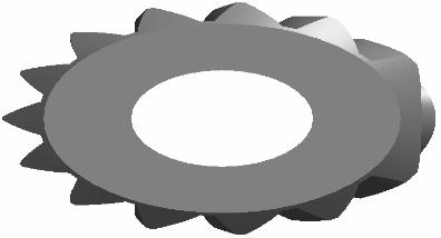
The CS gear is formed by engraving two axisymmetric tooth structures on a spherical material. Specifically, the tooth structure is first engraved on the surface of the sphere around the x axis like the tooth type is a tooth of ordinaryspurgear.Next,byadditionallyengravingaround the y axis, a quadrature spherical tooth structure around both axes is formed on the spherical surface. So, by revolvingthespurgeararoundthetwoperpendicularaxes the quadratic tooth structure is formed. This mechanism uses CS gears, but basic spherical gears are sometimes used for convenience when explaining the principle of the mechanism. The module of the involute tooth profile oftheCS gearisunconstrained.Incontrast,thenumberof teeth issubjectedtotwoconstraints.
1) Thenumberofthetoothmustbeeven.
2) The x and y axes are located in the center of the valleyorpeakofthetooth.
These conditions are necessary to avoid obtaining incomplete teeth due to the interference of the two tooth structuresandtomeshwiththeMP gear.
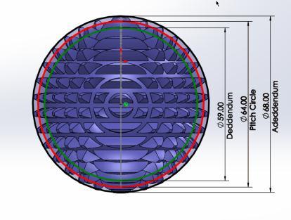
The pitch circle diameter mm, the addendum circlediameter mm,andthetoothdepth mmof a CS gears aredefinedasfollows,justlikethe typical spur gears:
Fig.4 spherical gear
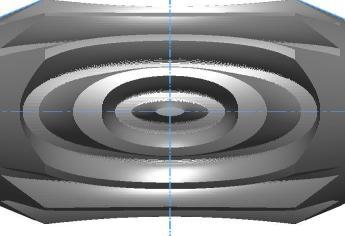
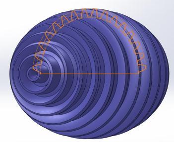
The MP gears have a unique tooth structure, the pole, whichcanmeshwiththeCS gears.Whenthez andx axes are aligned with the rotational axis and the pole an MP gearissymmetricinthex yplane
The module and number of teeth of the profileare,respectivelygivenby :
One pole of the MP gear can mesh to two poles of the CS gear in one complete revolution. To explain the tooth structure of the MP gear is shaped similarly to a basic spherical gear and is formed by rotating a typical gear profilearoundastructuralaxisThegearprofilesoftheMP gear are arranged on the same plane and mesh like a typical pair of spur gears. If the distance between the centers is fixed at some appropriate length, the system behaves as a planetary gear mechanism. The length of the carrier mm, the revolution angle of the planetary gear rad around the sun gear, and the rotation angle of the planetary gear rad are, respectively ,defined as follows:
( )
( )
The spherical gear is basically a rack cutter it engrave the tooth structure of cross spherical gear into the mono pole.
As the two poles of the basic spherical gear are symmetrical, an MP gear with half the number of teeth and only one pole can unlimitedly mesh with the basic sphericalgear.Thisbehaviorappearstodrawapolarorbit with respect to the CS gear Moreover, an MP gear can meshnotonlywiththebasicspherical gearsbutalsowith theCS gearspossessingtwostructuralaxes.
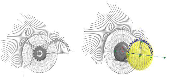
The large tooth width of the MP gear effectively constrains the CS gear, thus stabilizing “coupling motion.” The tooth width is determined by considering the size of the"Drivingmodule"
desired point. The controller attempts to reduce the error byadjustingthemethodofcontrolinputs.

This mechanism contains 4 motors each module has two motors one responsible for roll motion and the other for pitch motion these motion provide the cross spherical gearcoupling,gearingandslidingmotion
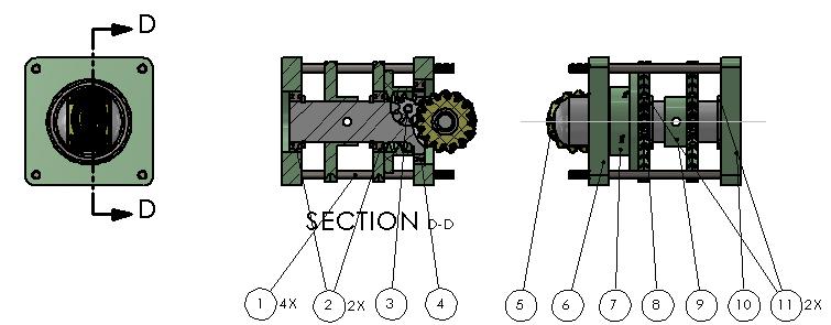
Fig.
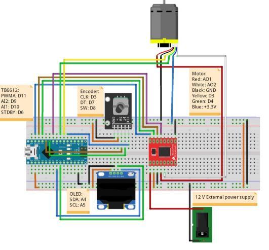
We use closed loop system Position Control of the DC Motor using PID Controller is a proportional integral derivative controller (PID controller). PID controller calculates an "error" value because of the difference between a measured process variable and therefore the
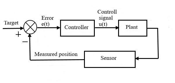
Fig. 9 Schematicdiagramoftheconnections
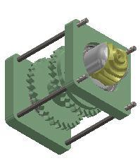
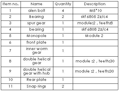
Thismechanismconsistof2drivingmodulesandcross spherical gear, first module driving module. The driving module contain an innovative gear called monopole gear itsdimensionillustratedinthefollowingfigures.
The second module is cross spherical gear, the part of our mechanism is the cross spherical gear where the output linkisfixedonthedesignmethodologyisexplainedbefore thefollowingfigureillustrateitsdimensions.
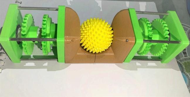
Finallytheorientationoftheoutputlinkwasmeasured by a motion capture system that originally had been coordinated8tomatchtheEuleranglesintheprototype.
Both perpendicular and opposite type prototypes were employed in this experiment. the measurement area was set as follows: Roll=±90, pitch=±45 (perpendicular type) or ±30 (opposite type), and yaw = 0 to 270. The target points were set in the area at equal intervals: Roll and pitch= 15 and yaw = 90. To reveal the continuity of positioning,thepositionmeasurementsweremadeateach targetpoint,approachingtheroll,pitch,andyawfromboth the positive and negative sides (±15 [deg]) taking the measurementsateachpoint.

Fig. 11:3DCADmodelsphericalgear
Experimentally test confirms the characteristics of the mechanismmentionedintheintroduction,i.e.,threeRDOF, absence of slippage and providing high range of motion Then,thecorrespondingresultsandthepractical issuesof themechanismarediscussed.
The accuracy of output link positioning is one and its high motion range ( in its two types opposite & perpendicular)willbetestedexperimentallyinthissection to confirm whether the theoretical motion range of the system is achievable in practice. OptiTrack V120 trio tacking system is used in this experiment to measure the orientationsontheoutputlink(trackingmark)
First the target points were regularly arranged in the configurationspacebasedontheEuleranglesinwithinthe motion range of the output link. Next the prototype was operatedtoreachthosepoints.
Positionsofthetrackingmarkerattachedtotheoutput link were measured To obtain the results of one measurement,anaverageof120measurementdataduring onesecondwasused.
In this section trajectory tracking will be discussed by experiment which verify the transient response of the mechanism’sprototypeasitmovesfromoneorientationto the other: The CS gear’s orientation is measured by following the trajectory of a straight line set in the r, p, y [deg] three dimensional configuration space. If the trackingoftheprototypeisgood,themeasurementpoints plottedinthree dimensionalspaceshouldbewelllinear.
To set up the measurement trajectory, we prepared reference points. The trajectory runs in sequence from P0 toP8.InonestraightmovementThefastestrotationisset to 90[deg/s], while the other two rotation speeds are adjusted to synchronize. Each reference point has a stoppingtimeof1s.TheCS gearorientationwasmeasured withaperiodof120Hz
Table 1: measurementtrajectory
measurement trajectory P0 P1 P2 P3 P4 P5 P6 P7 P8 r(aroundroll axis) 0 90 90 90 90 90 90 90 90 P(around pitchaxis) 0 45 45 45 45 45 45 45 45 Y(aroundyaw axis) 0 0 360 0 0 0 360 360 0
International Research Journal of Engineering and Technology (IRJET) e ISSN: 2395 0056

Volume: 09 Issue: 06 | June 2022 www.irjet.net p ISSN: 2395 0072
The results of the mates of innovative gears are to createmechanismwiththreeRDOFThechallengeinmulti degree of freedom mechanisms is the range of motion. In this mechanism there is two types of placing the two drivingmodules.Firstofthemisoppositetype180[deg].It provides a range of motion of 270, 90, 360 [deg]. The second one is perpendicular type 90 [deg] this range of motion is relatively high compared to other mechanisms and since our mechanism is a gear based mechanism it reduces slippage and provide high position accuracy as well as high torque and reliable transmission and those problemsoccurinmanyofsimilarmechanismthatprovide multidegreeoffreedomlikeourproject
A comparison of these movable ranges is shown in the followingtable2:
name type Ref.
Ourproject oppositetype Gears 270 90 360
Agileeye Linkage 140 140 30 [6]
Briglenetal Linkage 90 45 45 [15] Hess Coelhoet al Linkage 140 140 360 [16]
Hammondetal. Linkage 180 180 360 [17]
Kanekoetal Motor 30 30 360 [18] Yanoetal Motor 90 90 360 [19]
This study proposes a new mechanism based on spherical gear meshing, this mechanism can actively drive three DOF. During meshing, the two gear types interacted through gearing, coupling, and sliding motions, allowing a single MP gear to constrain or drive two DOF of the CS gear.ThisstudyproposesthatthethreeDOFoftheCS gear are achieved by driving two MP gears meshed with two phase differenttoothstructures.Thisideaisreinforcedby the mechanistic equivalence of the gear mechanism and a linkage mechanism. It also suggests that the mechanism’s capability of is independent of the positional arrangement oftheMP gears(drivingmodules).
[1] J Z A Deninson, “Vericle,” U.S. Patent US1928412 A, Jan 1930.
[2] P. Vasta, M. Franco, and M. Thomas, “Fixation device and multiple axis joint for a fixation device,” U.S. PatentUS8377060B2,Nov.2009.
[3] J. Robinson, J. Holland, M. Hayes, and R. Langlois, “Velocity level kinematics of the atlas spherical orienting device using omni wheels,” Trans. Can. Soc. Mech.Eng.,vol.29,no.4,pp.691 700,2005.
[4] J. Robinson, J. Holland, M. Hayes, and R. Langlois, “Velocity level kinematics of the atlas spherical orienting device using omni wheels,” Trans. Can. Soc. Mech.Eng.,vol.29,no.4,pp.691 700,2005.
[5] K.LeeandC.Kwan,“Designconceptdevelopmentofa sphericalstepperforroboticapplications,”IEEETrans. Robot.Automat.,vol.7,no.1,pp.175 181,Feb.1991.
[6] C. M. Gosselin, E. St Pierre, and M. Gagne, “On the development of the agile eye,” IEEE Robot. Automat.Mag.,vol.3,no.4,pp.29 37,Dec.1996.
[7] J. Robinson, J. Holland, M. Hayes, and R. Langlois, “Velocity level kinematics of the atlas spherical orienting device using omni wheels,”Trans. Can. Soc. Mech.Eng.,vol.29,no.4,pp.691 700,2005.
[8] K. Tadakuma et al., “Study on the omnidirectional drivinggearmechanism,”inProc.IEEEInt.Conf.Robot. Automat.,2012,pp.3531 3532.
[9] H. Y. Kim, H. Kim, D. Gweon, and J. Jeong, “Development of a novel spherical actuator with two degreesoffreedom,”IEEE/ASMETrans.Mechatronics, vol.20,no.2,pp.532 540,2015.
[10] K.LeeandC.Kwan,“Designconceptdevelopmentofa sphericalstepperforroboticapplications,”IEEETrans. Robot.Automat.,vol.7,no.1,pp.175 181,Feb.1991.
[11] K. Lee, H. Son, and J. Joni, “Concept development and design of a spherical wheel motor (SWM),” in Proc. IEEEInt.Conf.Robot.Automat.,2005,pp.3652 3657.
[12] K. N. Souza, R. S. Pontes, A. P. Oliveira, and G. A. Barreto,“Designandcontrolofathree coilpermanent magnetsphericalmotor,”Energies,vol.11,no.8,2018, Art.no.2009.
[13] H.Kim,H.Kim,D.Ahn,andD.Gweon,“Designofanew type of spherical voice coil actuator,” Sensors ActuatorsA:Phys.,vol.203,pp.181 188,2013.
[14] F. Chai, L. Gan, and L. Chen, “A novel tiered type permanent magnet spherical motor and its rotor orientation measurement principle,” IEEE Access, vol. 8,pp.15303 15312,2020.
[15] F. Chai, L. Gan, and L. Chen, “A novel tiered type permanent magnet spherical motor and its rotor orientation measurement principle,” IEEE Access, vol. 8,pp.15303 15312,2020.
International Research Journal of Engineering and Technology (IRJET) e ISSN: 2395 0056 Volume: 09 Issue: 06 | June 2022 www.irjet.net p ISSN: 2395 0072

[16] L. Birglen, C. Gosselin, N. Pouliot, B. Monsarrat, and T. Laliberte, “SHaDe, a new 3 DOF haptic device,” IEEE Trans. Robot. Automat., vol. 18, no. 2, pp. 166 175, Apr.2002
[17] L. Hammond, R. D. Howe, and R. J. Wood, “Dexterous high precision robotic wrist for micromanipulation,” inProc.16thInt.Conf.Adv.Robot.,2013,pp.1 8
[18] T. A. Hess Coelho, “A redundant parallel spherical mechanism for robotic wrist applications,” J.Mech. Des.,vol.129,no.8,pp.891 895,Sep.2006
[19] K. Kaneko, I. Yamada, and K. Itao, “A spherical DC servo motor with three degrees of freedom,” J. Dyn. Syst., Meas., Control, vol. 111, no. 3, pp. 398 402, Sep. 1989.
[20] T. Yano, T. Suzuki, M. Sonoda, and M. Kaneko, “Basic characteristics of the developed spherical stepping motor,”inProc.IEEE/RSJInt.Conf.Intell.RobotsSyst. HumanEnviron.FriendlyRobotsHighIntell.Emotiona Quotients,vol.3,1999,pp.1393 1398l