International Research Journal of Engineering and Technology (IRJET) e ISSN: 2395 0056
Volume: 09 Issue: 04 | Apr 2022 www.irjet.net p ISSN: 2395 0072

International Research Journal of Engineering and Technology (IRJET) e ISSN: 2395 0056
Volume: 09 Issue: 04 | Apr 2022 www.irjet.net p ISSN: 2395 0072
1Professor, Dept of Mechanical Engineering, Shri Ram Institute of Technology, Jabalpur, Madhya Pradesh, India
2Professor, Dept of Mechanical Engineering, Shri Ram Institute of Technology, Jabalpur, Madhya Pradesh, India
3Student, Dept of Mechanical Engineering, Shri Ram Institute of Technology, Jabalpur, Madhya Pradesh, India
Abstract Wheel rims are the most important part of automobile, in an automobile there are fatigue loads and staticloadswhichareactivelyparticipatedindesign.There areseveralwayoffailureofwheelrimlikecriticalstresses andmaterialfailureduetodesign,dimensionandshapeof wheel also play vital role in its rim design. Present paper studied the Y angle optimization in alloy wheel rim. The present project design is modeled by using modeling softwareCATIAv5,importedanalyzedbyANSYSsoftware.
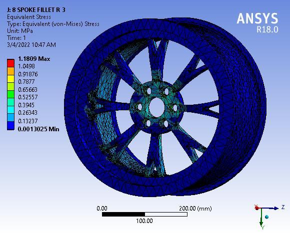
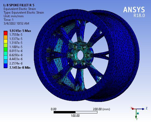
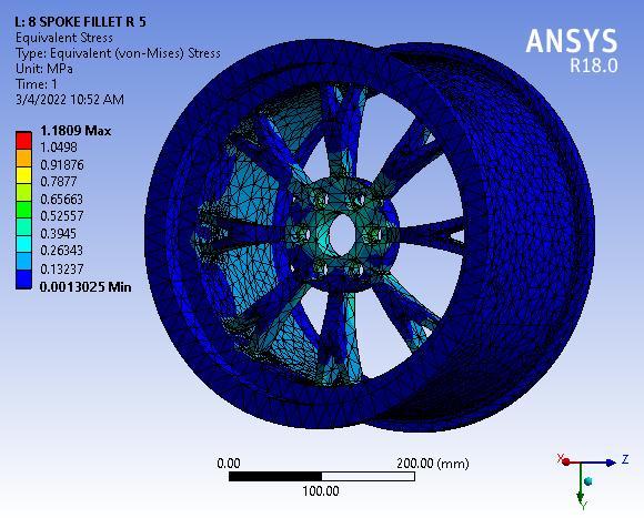
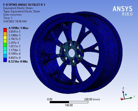
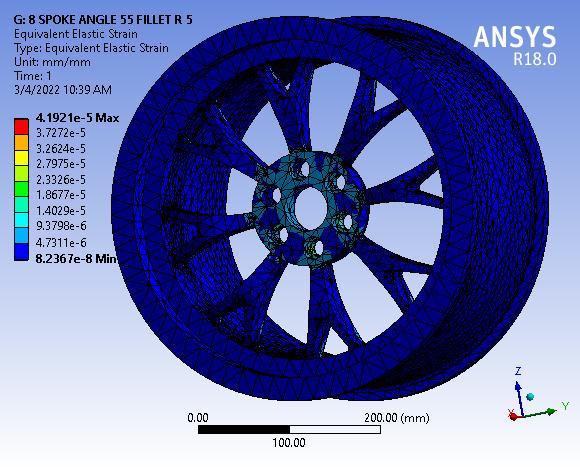
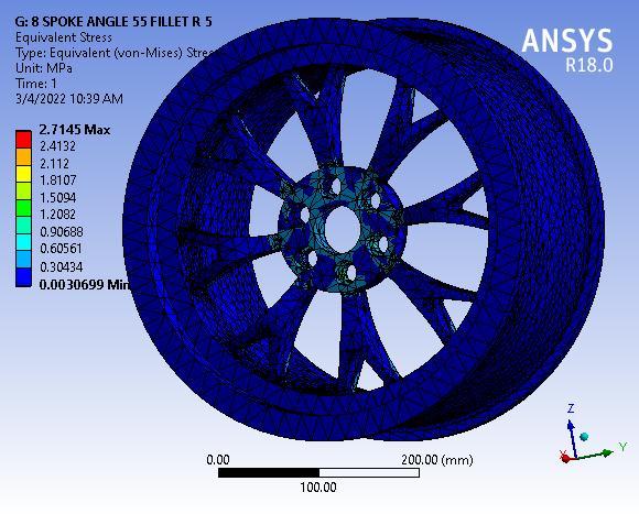
For the structural analysis for the remote force the magnitude applied is 1000N and for the pressure which appliedonthewheelis245kPa.
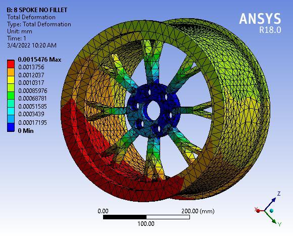
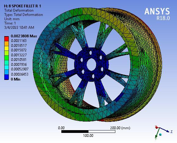
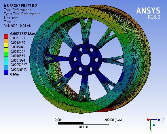
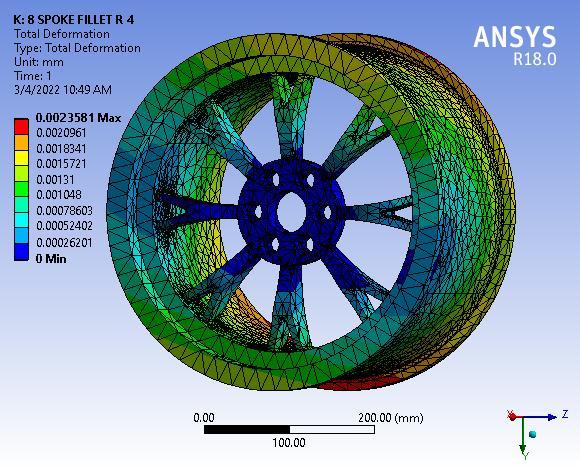
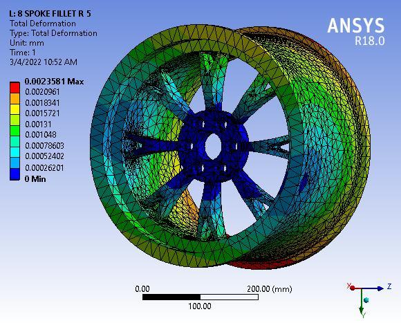
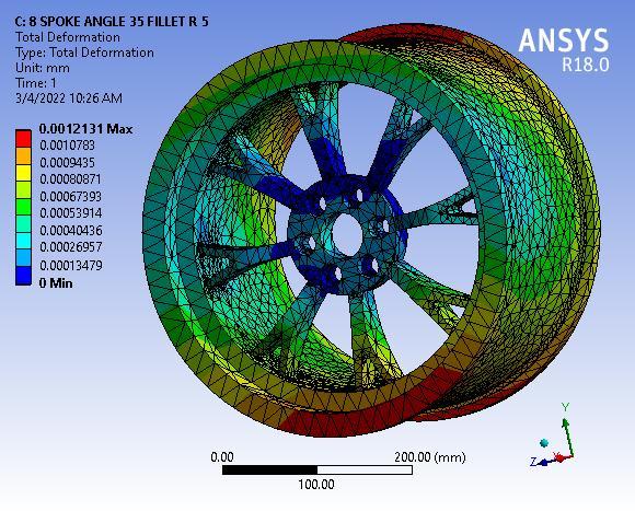
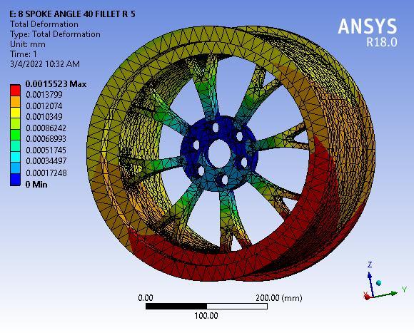
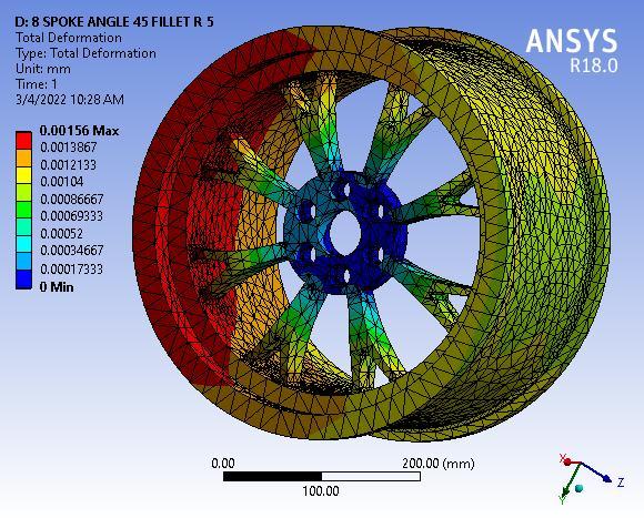
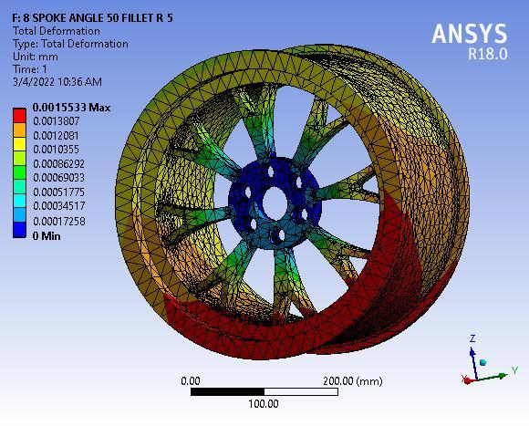
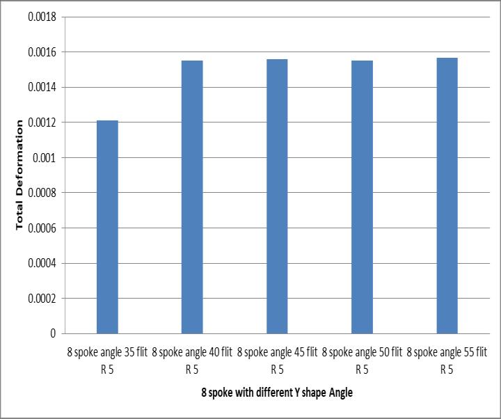
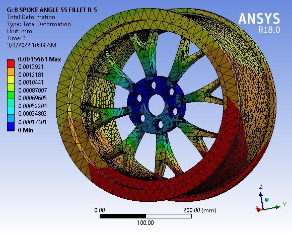
Finallyresultshowsthetotaldeformationof8spokealloy wheel with 55° Y spoke angle, figure clearly depicted the totaldeformationmaximumvalue0.00155mmmaximumat baseofwheelorouterperipheryofwheelrim.
Wheel should be in proper balancing in statically and dynamicallybothconditions.Wheelshouldbelightinweight witheaseinmountingandremoving.Wheelmaterialshould havegoodinstrengthaswellaslesscorrosivetoweather conditions.Thewheelhaswellinsteeringcontrolandableto absorb shock loads, it should also be able to resist deformationagainstimpactloadduringbump.
More popular and standard part of vehicles. They also added the sophistication to vehicle with light weighting Constructionsof wheel for moderncarshavestarted with steelwheelswhichareusuallyconstructedwithmetalsheet andthenweldedtogether.Duetodurability,flexibility,and greaterstrengthofmateriallikesteeltheyarestillinuse,but thedisadvantagewithsteelwheelsistheirheavyweight
Origin of human civilization is truly stated with inventionofwheelandabsolutelyitissignificantdiscovery of evolution of human race. The invention of wheel acceleratesthetransportationidea. Bydefinition,wheelisa part with circular shape which rotates around axle and enable the rolling motion of vehicle. Inception concept of wheel is simply wooden disk with hole manufactured for cart or bullock cart. Wheel with spoke is used for construction of lighter and speedy vehicle. Designing and production of modern motor vehicles follows strict guidelinestoensuresafetyoftravelers.Eachcomponentof vehicle may have to follow criticality of each design consideration.Simplytheautomobilewheelsdistinguished asperinternationalcodingsystem.
Therearethreeelementsinwheelclassifiedashub, spokes, and rim. Components related to design may be constructedinoneormultipleparts.Firstly,thehubisbasic centrally located and attached through wheel knuckle. Secondlythespokesactasbridgebetweenhubandrim.At last,therimwhichisoutermostpartofwheeltograsptype. Therearefewessentialcharacteristicsforwheelofvehicle.
Toreducetheweightincarwheelstoachievebetter stability and dynamics of vehicles, car manufactures introducedthealuminumwheelsasadd onstovehicles.But technologies shifted to more organized sectors and aluminumwheelsbecomemeasure,aswellasstylishfeature incars. Aluminummodeledwheelsstarteditsflagshiptoall luxuryvehicleswithexclusivelypersonneltouchedreason.
In1948forgedaluminumwheelinventedinALCOA and 1962 the Porsche with aluminum alloy increases the popularityofforgedaluminumwheels.Thepenetrationof aluminum in wheels was approx. 35 % in the year in Europeancontext,whichisnearabout1.5timesascompare withUSAandJapan.Nowadaysaluminumwheelsincrease their popularity in commercial market. Nowadays, the growth rate of the aluminum wheel market has slowed down,butthemarketvolumeisstillincreasing.
Inmoderndaysthealuminumwheelsaremadebycasting and forging processes. Performance of wheels is directly propositional to the manufacturing process. Their performance is a direct result of the employed manufacturingtechnique.Forgedwheelsarestrongeroneas wellaslighter.Castingwheelsareknownasdurableonesfor moderateconditions.Themanufacturingofwheelclassified intotwotypesaspermanufacturingprocess
© 2022, IRJET | Impact Factor value: 7.529 | ISO 9001:2008 Certified Journal

International Research Journal of Engineering and Technology (IRJET)
Volume: 09 Issue: 04 | Apr 2022 www.irjet.net
i. Castaluminumwheels
ii. Forgedaluminumwheels
Alloy wheels are basic combination of two materials: aluminumandmagnesium.Basically,twotypesofalloytype usedinmanufacturinginwheels,firstisAlSi1MgMn(6082) andotherAA6061(AlSiMgCu).Recentlymanufacturingwith Titaniumisbeingmeasuredforbetterdurabilityandshock absorbing. Different Spoke design is also considered for betterdurabilityanddesignconsideration,anditshouldbe abletofaceallconsequenceswhileridingthevehiclesinall terrainsofroads.
Magnesium alloy wheels are sometimes used on special cars (sports cars, upper class models) for better performanceinsteadofheaviersteeloraluminumwheels. Thesewheelsareproducedbyhotforgingorcastingfrom magnesiumalloyssuchasZK60,AZ31orAZ91.Theirtypical massisabout5 9kg(dependingonsize).Butapartfromthe high price, magnesium wheels have also additional disadvantagesfornormalroaduse(flammability,corrosion resistance)
P. Meghashyam et.al studiesthecarwheelrimdesignedby CATIA to reduce the risk involved in manufacturing and design. Further it is analyzed by ANSYS software, in this analysisthe3Dmodelexportedandsimulatedwithdifferent forces and pressure. ANSYS used static model of analysis, wheretwodifferent modelsofaluminumand forgedsteel were calculated for wheel rim component. Structural behaviorofrimmodelanalyzedbyinputdataofsoftware, calculationofdifferentrimmodelANSYSworkbenchisused withdifferentmaterialslikeSteel,Aluminumalloy,Titanium alloy,Magnesiumalloy.Astandardrimsizei.e.17Inchtaken for analysis as per SAE standard with fixed ends for lug holes. Total 0.35 MPa applied on the wheel barrel with different materials. In all four possibilities the best suited materialisaluminum,thesecondbestmaterialistitanium alloy, but high cost makes the titanium alloy non commercial.
Hence,titaniumalloyisbettersuitablematerial if costisnoissue;otherwiseAluminumAlloyamongthesefour materialsisgoodforwheelrimobtainedfromthisresearch analysis.
Sunil Prashanth Kumar et. al studiesthealuminumalloy and steel rim, designed in Auto CAD 2022. The project is analyzedwithANSYSsoftwarewithtwocategorysteeland aluminumalloy.Studyoccurredintwodesignfirstsimplysix spokedesignandsecondoneismultispkealloy,wheretotal force applied is 1000N and pressure 245 kPa. In result comparsionalloywheelshavelessdeformationascompared
e ISSN: 2395 0056
p ISSN: 2395 0072
withsteelones.Indesignformatthereismultispokealloy havebetterresultsthan6spokealloywheels.
Manugonda Babu et al researchesonshapeanddimension constraintofwheelrimbasically.Themodeellingofwheel riminitiatedinCATIAby3Dmodel,furtherworkofanalysis isdonebyANSYSsoftware,wheredifferentconstraintslike deformation, strains and stress are calculated. Overall analysisisconsideredondifferentmaterialwheelrimlike carbon fibre, aluminum and Kevlar. Wheel rim also subjectedwithfatiguestructuralanalysis.Thisresearchalso recommended the best material and weight comparison between all materials chosen. Along with these materials Kevlar chosen with best suitable material with all constraintslikefatigueandweightreduction.
M.Ravichandra et al studieddifferentautomotivewheels with different materials like carbon epoxy, E glass and S glass.Alloywheelshavebetterstabilitycontrolwithgreater steeringqualityandlessinweight.Inthispapercomposite materials studied with their data of present automobile, resultsarecomparedwithallotherdatawithexistingmodel. In this project a parametric model is designed for Alloy wheelusedinfour wheelerbycollectingdatafromreverse engineering process from existing model. The designed modelanalyzedwithultimatestrengthofthreecomposite materialswithhelpofPro EmodelandAnsysModel.
Instudyofautomobilewheelrim,differentreview suggested the different stresses during loading. Basically, wheelrimissubjectedwithbendingandtorsionalload.The basic need of better rim structure is long life, weight reductionandmaterialselectionforbettermanufacturing.In commercial world the need of low manufacturing cost as well as less weight and low cost is necessary. There are competitionsamongmaterialsandmanufacturingprocesses, duetocostperformanceandweight
In present research work FEM is most promising methodtounderstanddifferentparametersofdesign.The finiteelementmethodiscomputationalmethodtocalculate different parameter of design by introducing different boundary condition. The mathematical problem in which differential equations set with variables with specific boundaryconditionstoobtaindifferentresults.Theiterative mathematicalprocesseslikeasGalerkin’sweightedresidual methodandRaleigh Ritzmethodscastofftogainthefinite element formulation of the partial differential equation. ANSYS Static Structural is a valuable tool for examine problems connecting contact, huge distortions, nonlinear materials,highfrequencyreactionphenomenaandproblems needingexplicitexplanations.
International Research Journal of Engineering and Technology (IRJET)
Volume: 09 Issue: 04 | Apr 2022 www.irjet.net
Designing the alloy wheels are based on the manufactures but the steel wheels are same for every manufacture,sothedifferentdesignedmodelsare
Herethematerialandthepropertiesareusedbasedonthe aluminum alloy. Totally, six spokes are there in this alloy withdimensionsanditisdonestructuralanalysis
Thematerialusedissameasthatof6spokealloywhichis aluminum alloy and their properties for the purpose of analyzingitandtoidentifystructuralanalysisofthewheel. Heremorespokeshavebeendesignedtofindoutwhichone ofthealloywheelshasmorestrengthinthestructure.
Itisdesignedtoidentifyissteelorthealloyisbetterinthe structural analysis. Steel is the main material used to produce the steel wheel, here the material used for the analysisofthestructureisusedthestructuralsteelandtheir properties.
Dimensionsareequalforallthethreetypesofwheelsfor 6 spoke alloy wheel
Rimdiameter=410mm
Rimwidth=465mm Centerbore=40mm Boltcircles=20mm Spokelength=200mm
For steel wheel, Rimdiameter=420mm Rimwidth=245mm Centerbore=35mm Boltcircles=20mm Circlesaroundtheouterarea=25mm
For multi spoke alloy wheel, Rimdiameter=420mm Rimwidth=230mm Centerbore=30mm Boltcircles=15mm Spokelength=200mm
2022, IRJET
e ISSN: 2395 0056
p ISSN: 2395 0072
Fig 1: DesignModelof8SpokeAlloyWheel
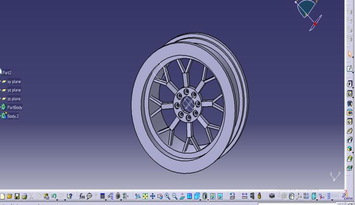
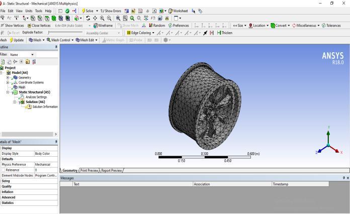
Fig-2: Meshingof8SpokeAlloyWheel
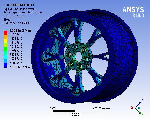
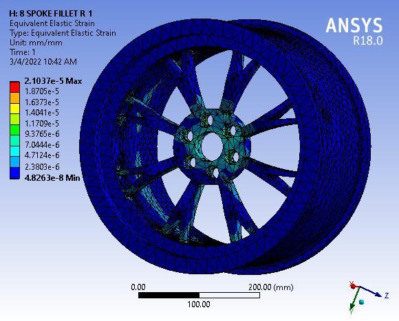
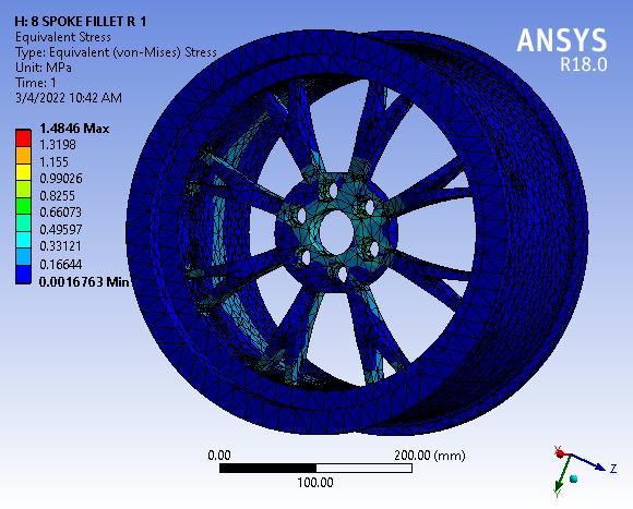
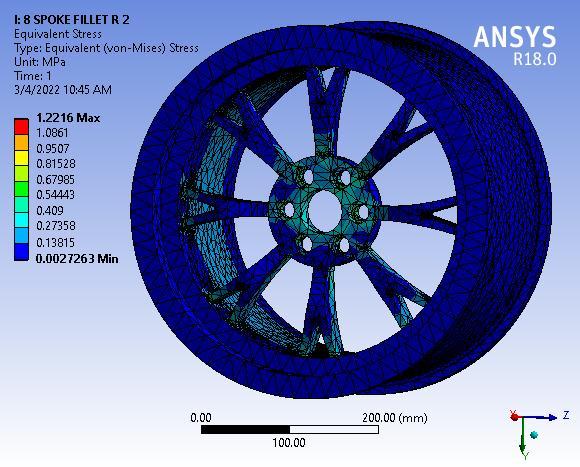
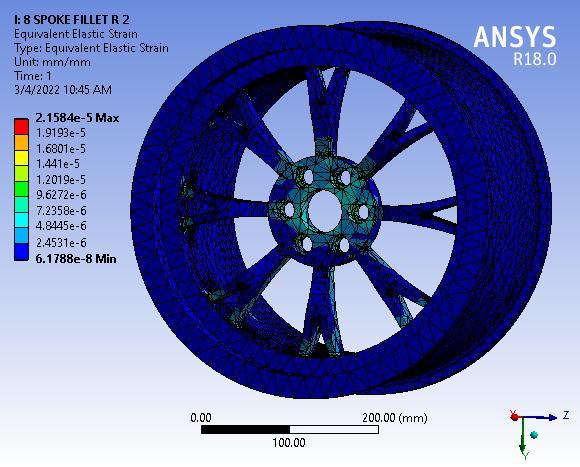
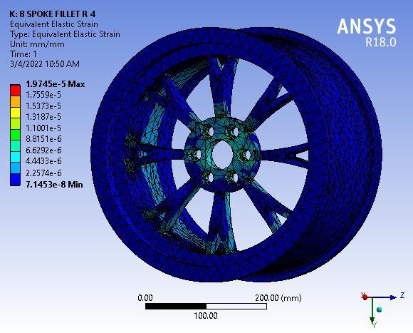
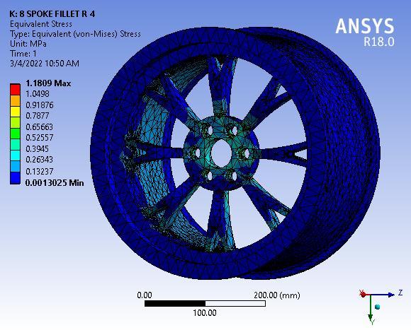
Differentmodelanalysiswithnofillerradiusto5mmfillet radiusvaried.
Wheel Rim with No Fillet
Impact Factor value: 7.529
Fig 3: TotalDeformationof8SpokeAlloywheelwithNo filletradius
ISO 9001:2008
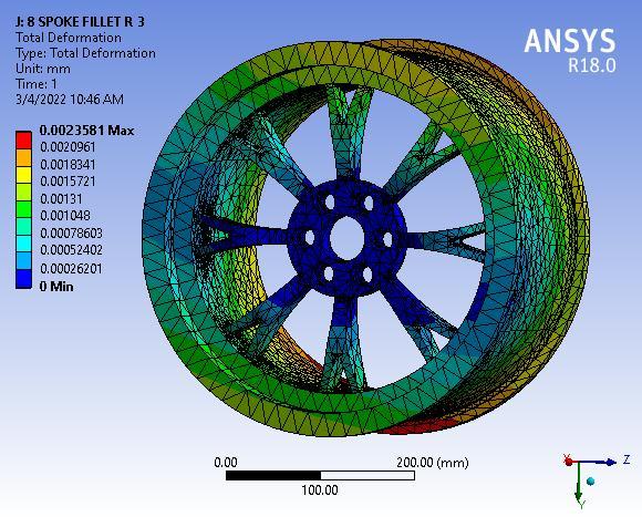

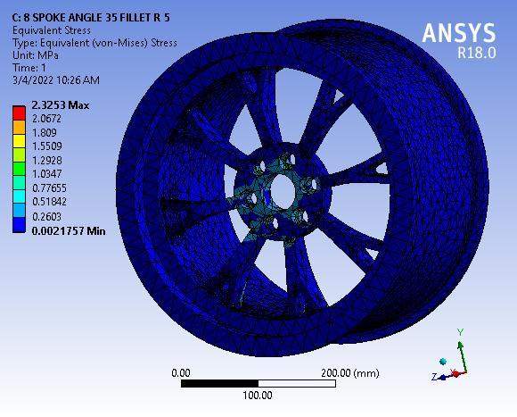
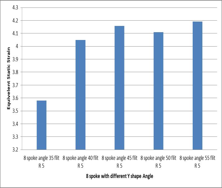
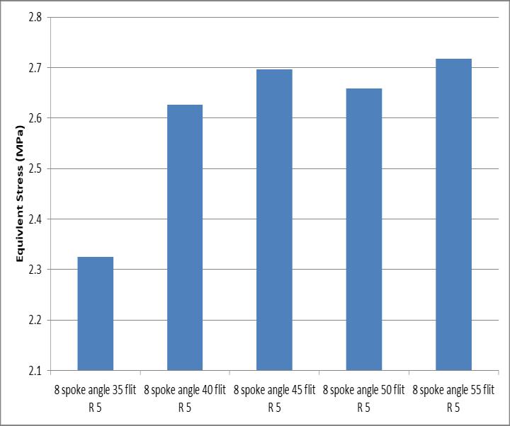
Variationinthissecondmodelpresentresearchemphasison variation in Y spoke model is carried out with angle with 5degreevariation.Atfirstthereis35degreespokeangle.


e
p
International Research Journal of Engineering and Technology (IRJET) e ISSN: 2395 0056
Volume: 09 Issue: 04 | Apr 2022 www.irjet.net
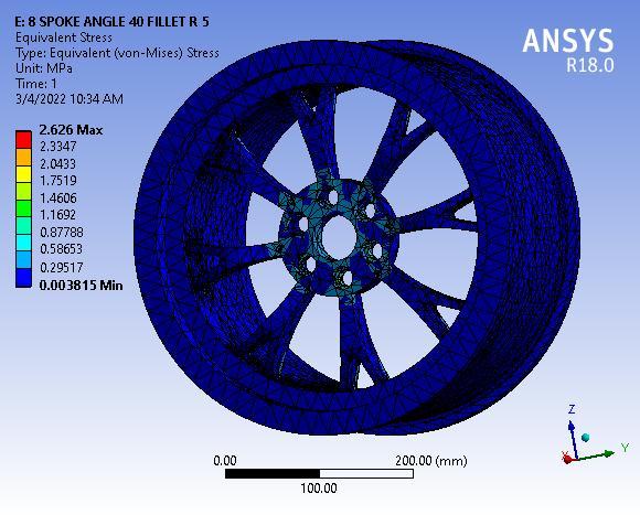
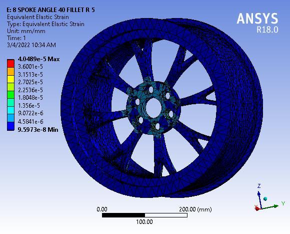
For the structural analysis for the remote force the magnitude applied is 1000N and for the pressure which appliedonthewheelis245kPa.
Therefore, so comparing the wheels with the total deformationoccurredalloywheelsarebetterthanthesteel wheel,andcomparingtheboththealloywheelsmulti spoke alloywheelisbetterthanthe6 spokealloywheel.
Since the alloy wheel have some dis advantages then also consideringtheresultsalloywheelshavebetterstructural tendencythanthesteelwheelsandifthespokesare
1) Static and dynamic analysis of wheel rim can be done together.
2) For static load car weight can be considered and for dynamicconditionaccelerationloadcanbeconsidered.
3)Forpracticalrealisticconditionharmonicexcitationcan beconsidered.
4)Alltheabovefactorscanbeconsideredonthreedifferent materials which after comparing in Ansys software; will suggestwhichthebestmaterial.
1. P.Meghashyam,S.GirivardhanNaiduandN.Sayed Baba, Design and Analysis of Wheel Rim using CATIA&ANSYS,InternationalJournalofApplication or Innovation in Engineering & Management (IJAIEM),Volume2,Issue8,August2013.
2. Sudhakar Mishra, Dr. L.P. Singh, Structural and Material Analysis of an Automobile Wheel Rim using ANSYS, International Research Journal of Engineering and Technology, Volume 06 Issue 1, Dec2019.
3. Mr.SunilPrashanthKumar,MuhammadMansoorP, Vishak Vignesh, Abhijeet Kumar, Mordi Sangma, Design And Analysis of Automobile Wheel Rim InternationalResearchJournalOfEngineeringAnd Technology (Irjet) E Issn: 2395 0056 Volume: 08 Issue:07|July2021
4. ManugondaBabu,Dr.V.S.Hariharan,Modellingand Analysis of Automotive Wheel Rim, International Journal of Innovative Research in Science, EngineeringandTechnology,Vol.5,Issue4, April 2016.
5. M.Ravichandra,S.RameshKumarbabu,A.Salmon, P.Nagaraju,DesignandStructuralAnalysisofAlloy WheelsforLightWeightVehicles,IOSRJournalof
p ISSN: 2395 0072
MechanicalandCivilEngineering, Volume12,Issue 6 Ver.V(Nov. Dec.2015),PP73 82
6.https://en.wikipedia.org/wiki/Alloy_wheel
© 2022, IRJET | Impact Factor value: 7.529 | ISO 9001:2008 Certified