International Research Journal of Engineering and Technology (IRJET) e-ISSN: 2395-0056

Volume: 09 Issue: 12 | Dec 2022 www.irjet.net p-ISSN: 2395-0072

International Research Journal of Engineering and Technology (IRJET) e-ISSN: 2395-0056
Volume: 09 Issue: 12 | Dec 2022 www.irjet.net p-ISSN: 2395-0072
Abstract - Automation is one of the main priorities of various industries to achieve better efficiency and less error in the process which are carried out within the industry. Today industries are trying to move toward automation to increase production and quality of product. So, by taking this point into consideration and by taking it as an opportunity to contribute in this domain we tried to make demonstration model for educational use. In this project automatic electro pneumatic gantry type sorting conveyor system has been used for sorting the object based on its parameter such as metallic properties and colour. For this purpose, we have used the PLC (Programmable Logic Controller) which is controller that is used for controlling the various processes required to sort the material. In order to give the input and check the process and various parameter while the system is running, we have integrated the PLC with HMI (Human Machine Interface). The various sensors and relays are used in this project and the sensors are connected to the PLC. PLC controls the process and carries out the sorting of material with the help of actuators.
Key Words: Automation Production, Electro pneumatic Gantry type Sorting robot, Conveyor System, PLC (Programable Logic Control), HMI (Human Machine Interface).
A worker who has been performing a repetitive task undergoes fatigue. Worker fatigue on assembly lines can result in poor quality control, reduced performance and sometimesitcanbeharmfulforthatworkerorsurrounding people. But machines can perform highly repetitive tasks muchbetterthanhumans.So,byintegratingautomationin industrymayhelptoimproveproductqualityandefficiency of manufacturing system. So, by taking these points into consideration and by taking it as an opportunity to contribute in this domain we developed demonstration model of electro pneumatic sorting system as a setup in which we can get hands on experience on industrial automationaspectssuchasproductdesigning,workingof different types on sensors, integrating sensors with actuators, Operating the system using programable logic controllerandinterfacingprogramablelogiccontrollerwith humanmachineinter-face.Inthischapter,weidentifythe problem statement, objectives, methodology and main component that will be used in the project. The electropneumatic automatic sorting machine consists of some
sensors, actuators which are controlled by program- able logiccontroller(PLC).
To make a prototype of Electro-Pneumatic pick and place gantrytypesortingrobotusingpneumaticcomponentsand sensorsandinterfacingthemwithPLCandHMI
Ourobjectiveistodesignsystemsothatmaterialhandling process facilitate easy, cheap, fast and safe loading and unloadingwithoutorwithleasthumaninterference.
To study the operating condition of sensors and actuatorsusedinsortingsystem.
To design and fabricate gantry system on conveyor beltforpickandplaceoperation
Todevelopautomatedsystemforevent-basedcontrol, InterlockingandSequencingofoperation.
ToperformexperimentationandvalidationofElectropneumaticpickandplacegantrytypesortingrobot.
ThisprojectwillhelptolearnalltheinsidesofanIndustrial AutomationandMaterialHandlingsystem.
Itwillhelptolearnvariousaspectsofautomationlike PLC,HMIandSensoretc.
ItwillalsohelptolearnPLCprogrammingaswellas theintegrationofalltheelementsinthesystemwith thePLC.
It will help to learn how to display and set all the processing data on to the HMI (Human Machine Interface)screencanbelearned.
By understanding the robot’s operation and programming onecanabletodesignandfabricateactualworkingrobotfor theindustrialapplication.
International Research Journal of Engineering and Technology (IRJET) e-ISSN: 2395-0056
Volume: 09 Issue: 12 | Dec 2022 www.irjet.net p-ISSN: 2395-0072
Aconveyorbeltisthecarryingmediumofa beltconveyor system
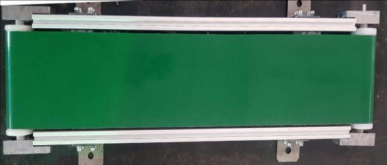
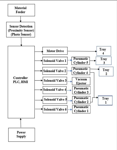
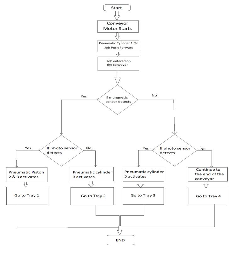
Chart-2showsthestepsanddecisionsthatareneededto performsequentialsortingprocess.Thiswillallowanyoneto logicallyfollowtheprocess from beginningto the endand willhelpduringmakinglogicfortheladderprogramming.
Chart -3 shows the block diagram that represents the principalpartsofthesystemandtherelationshipbetween them.
Fig -1:ConveyorBelt
Inductive proximity sensors are used for non-contact detection of metallic objects. Their operating principle is basedonamagneticfieldisgenerated.
Photoelectric sensor consists of a built-in emitter and receiverunit.Thephotoelectricsensorisnormallyopenand PNP type, the basic workingprincipal is reflection oflight. Theemitteremitsthelightbeamontothematerial,thelight getsreflectedfromthematerialsurfaceandisreceivedbythe receiver.Basedonthissignalitgivescorrespondingoutputto thePLC.Inthisprojectwehaveusedtwotypesofsensori.e. E3FA-DP12 sensor with plastic housing and E3FB-DP12 sensor with metal housing, although the all the other parametersareidentical.Thesensitivityofthesensorcanbe adjustedusingthesensitivityadjusterscrew.
A Programmable Logic Controller (PLC) is an industrial computerized control unit/controller which continuously monitorsthesignalsofinputdevicesandmakesdecisions baseduponacustomprogramaccordingtotheapplication, tocontrolthesignalsofoutputdevices.ThePLC-typethat willbeusedisDELTA-DVP14SS211Rthathas8inputsand6 outputs,additionallyweusedDELTA-DVP16SP11Rextension modulewhichhas8inputsand8output.WechoseDeltaPLC because of its good quality, easy to be programmed, has acceptedthepriceandmeettherequiredpurpose.
Chart -3:WorkingPrincipleBlockDiagram
International Research Journal of Engineering and Technology (IRJET) e-ISSN: 2395-0056
Volume: 09 Issue: 12 | Dec 2022 www.irjet.net p-ISSN: 2395-0072
ATheHMI(HumanMachineInterface)systemrepresentsthe interface between the worker (operator) and machine (process/plant).The actual unit which controls all the processes is PLC. Hence, there is an interface requirement between the worker (operator) and HMI device and an interfacerequirementbetweenHMIdeviceandthePLC.In thisprojectweusedDOP-B035211DeltaHMIwhichhas4.3 inchtouchdisplay.
EmergencyStopButtonprovidessafetyforhumansandthe machine;itoffersawiderangeofsafetycomponentsforthe protection of humans, machine and production goods in emergencysituations.Thepurposeoftheemergency-stop device is to deflect or minimize the risk as quickly as possibleandoptimallyintheeventofanemergencyarising.
A circuit breaker is an automatically operated electrical switchdesignedtoprotectanelectricalcircuitfromdamage causedbyexcesscurrentfromanoverloadorshortcircuit. The main function of circuit breaker is to protect the electrical devices and humans from the risk of electric current by cutting the circuit in the case of an unusual currentinthecircuit(overloading,shortcircuitorleakage current).
Fuse terminal Blocks are intended to protect motors, controllersandbranch-circuitconductorsagainstexcessive heatingduetolongmotorovercurrentandincludinglocked rotor currents. Protection of the motor and other branchcircuit components from higher currents, due to short circuits or grounds, is a function of branch-circuit fuses, circuitbreakersormotorshortcircuitsprotectors.
Adouble-actingpneumaticcylinderisonewherethethrust, oroutputforce,isdevelopedinbothextendingandretracting directions.Double-actingcylindershaveaportateachend andmovethepistonforwardandbackbyalternatingtheport that receives thehigh-pressure air, necessary when a load must be moved in both directions such as opening and closingagate.
Thesolenoidvalveisanelectro-mechanicaldeviceusedfor controllingliquidorgasflow.Thesolenoidvalveiscontrolled byelectricalcurrent,whichisrunthroughacoil.Whenthe coilisenergized,amagneticfieldiscreated,causingaplunger insidethecoiltomove.Dependingonthedesignofthevalve, the plunger will either open or close the valve. When electrical current is removed from the coil, the valve will returntoitsde-energizedstate.
Avacuumejector,orsimplyejectorisatypeofvacuumpump, whichproducesvacuumbymeansoftheVenturieffect.Inan ejector,aworkingfluid(liquidorgaseous)flowsthroughajet nozzle into a tube that first narrows and then expands in cross-sectionalarea.Thefluidleavingthejetisflowingata highvelocitywhichduetoBernoulli’sprincipleresultsinit havinglowpressure,thusgeneratingavacuum.
Anaircompressorisapneumaticdevicethatconvertspower into potential energy stored in pressurized air (i.e., compressed air). By one of several methods, an air compressor forces more and more air into a storage tank, increasingthepressure.Whenthetank’spressurereachesits engineered upper limit, the air compressor shuts off. The compressedair,then,isheldinthetankuntilcalledintouse
Inthissortingmechanismweusedgantrytopickandplace objects in their respective trays. As shown in Figure 3.1, Gantry has motion in x and y-direction and supported by roller wheels. In total 12 roller wheels are used for xdirection motion and 6 wheels are used for y-direction motion.Soweneedtofindtheforcerequiredtomovethe gantry.
Accelerationduetogravity(m/s2)
International Research Journal of Engineering and Technology (IRJET) e-ISSN: 2395-0056
Volume: 09 Issue: 12 | Dec 2022 www.irjet.net p-ISSN: 2395-0072
Fr=c*W
=0.057*49.05 = 2.796 N
Where:
Fr:Rollingresistanceorrollingfriction(N)
c:Coefficientofrollingfriction
ForceRequiredtopushtheGantry=Pullingforce
PullingForce(P)=rollingresistance
PullingForce(P)=2.796N
Butweareusing12wheels
TotalForce(Ft)=12*2.796
TotalForce(Ft)=33.55N
To push the Gantry we are using Pneumatic piston.
2.2 Selection of Conveyor Motor
PROPERTIES
VALUE
AluminiumDensity 2710Kg/m3
BeltDensity 1000Kg/m3
BeltThickness 0.0015m
BeltWidth 0.14m
DiameterofPulley 0.050m FrictionofCoefficient 0.5
Table
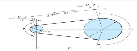
Conveyorbeltsareelastic/flexiblemachineelementsthatare usedinconveyingsystemsandinthetransmissionofpower over comparatively long distances. Because of its inherent advantage that it can absorb a good amount of shock and vibration.Itcantakecare ofsomedegree ofmisalignment betweenthedrivenandthedriverpulleys.Fig9showsaflat beltgeometry
Length of Conveyor Belt = 2 * (CD) + 2 * (.r)
LengthofConveyorBelt=640+640+2+3.14*(53/2)
LengthofConveyorBelt=1280+166.5 LengthofConveyorBelt= 1446.5 mm
Weight of Belt = Length * Thickness * Width * Density WeightofBelt=1.4465*0.0015*0.140*1000 WeightofBelt= 0.303 kg
Assuming,Externalforce=100N Max.WeightofObject-0.2Kg
Torque required to drive the conveyor belt(T)
= 0.5 * D*[F + ( * W * g)] Nm
=0.5*0.053*[100+(0.5*0.2*9.8)] = 2.675 Nm
Were
D=RollerDia.(m) W=LoadMass(Kg) g=GravitationalAcceleration(m/s2) F=ExternalForce(N) =FrictionCoefficient
Generally,duetomanufacturingdefaults,misalignmentsand othervariousfactorstheoretical valuesvariesfromactual valuestherefore wewill selectconveyor motor whichhas moretorquethancalculatedtorque.
Pneumaticcylinderswereusedinthissystemtopushand pullgantry,toliftcom-ponentsfromconveyorbelt,tofeed componentstotheconveyorbeltandtorejectcomponents from conveyor belt. Due to time constraints we selected standard double acting pneumatic cylinder from market, thesecylinderhavingborediameterrangingfrom12mmto 25mm,andstrokelength rangingfrom10mmto300mm. Accordingtoourapplicationweselectedtwodoubleacting cylinderhavingborelength 12mmandstrokelength250 mm,andthreedoubleactingcylinderhavingborelength12 mmandstrokelength100mm.Nowtocheckwhetherthis cylinders can lift the load we performed following calculations,forreferenceseeChart-
International Research Journal of Engineering and Technology (IRJET) e-ISSN: 2395-0056
Volume: 09 Issue: 12 | Dec 2022 www.irjet.net p-ISSN: 2395-0072
PLCInput-Outputtable
Table2and3showsthePLCI/O’s
Chart -1:CylinderSpecification
Theoreticalpullforceis:
F = (D2/4 – d2/4) P
F=3.14*(0.0122/4-0.0062/4)*500000 F= 42.39 N were, F=force,N D=cylinderbore,m P=pressure,N/m2 d=pistonroddiameter,m
For sliding gantry, required force was 33.55 N. Therefore, selectedcylinderwillsatisfytherequirement.
Ageneralruleofthumbisthatforverticalandhigh-friction applications,therequiredforceshouldbetwicetheloadtobe moved.
Therefore, Feffective = 21.195 N
Forliftingtheobjects(havingmaxweight,1.962N)fromthe conveyorbelt,requiredforceis1.962N.Therefore,selected cylinderwillsatisfytherequirements
Using of relay-based switches to implement basic logical expressions and some examples of logic-based industrial systemcontrol.Thistypeofcontrolsystemdetectsthestatus ofinputslikeswitchesandotheron-offlogicalandthenuses relays, timers, and counters to implement logic and drive outputsbyenergizingtheoutputcoilofsomesortofvalveor anotheractuator.
Table -2: InputMapping
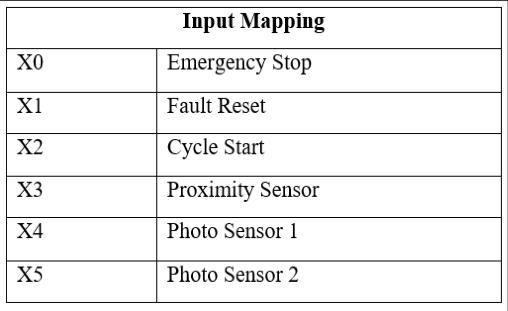
Table -3: OutputMapping
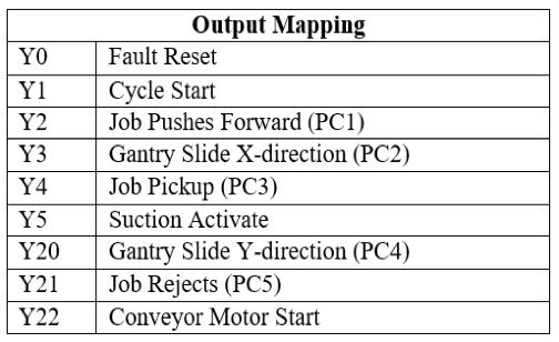
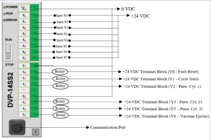
FIG10showsPLCcontrolcircuitofmachine.
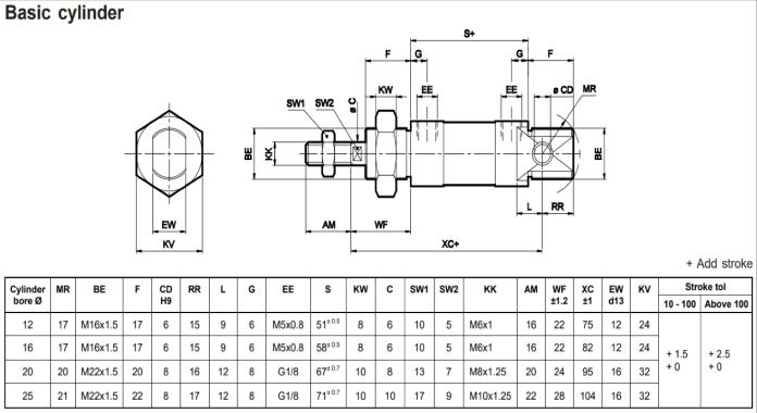
Fig -10:PLCConnections
International Research Journal of Engineering and Technology (IRJET) e-ISSN: 2395-0056
Volume: 09 Issue: 12 | Dec 2022 www.irjet.net p-ISSN: 2395-0072
assembled conveyor, gantry frame and collecting trays on woodenboard.
3.2.1
After calculating torque needed to run the conveyor, we purchasedOrangeMG55512V10RPMSquareGearboxDC motorandattachedthemotortoconveyorbyusingflexible coupling. This motor has higher torque than that we calculatedinchapter2,stillweselectedthismotorbecauseit wasavailableatthetimeandalsoitwascheaper
Inthissystemallthesortingprocessisdoneaftercollecting datafromsensors.InthismodelweusedOrange8mmPNP InductiveProximitySensorandOmronPhotoelectricSensor E3FA-DM13
Since we were using two sensors, emergency stop switch, faultresetswitch,cyclestartswitch,sixsolenoidvalvesand oneDCmotorweneededtotal9outputand6inputportsbut our main PLC module DVP14SS211R has only eight input and six output ports, so we purchased Extension Input output module DVP16SP11R to meet our requirements. After installing PLC in control panel, we tested them and theyworkedsuccessfully
3.2.4
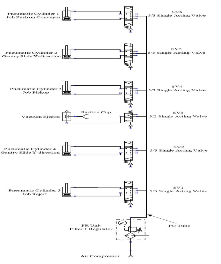
Fig -11:PneumaticPowerCircuit
This Section provides work implementation, which is dividedintothreesubsystems
3.1.1
AccordingtoChapter2,aftercalculatingnecessaryvalueswe buildthemodularconveyorbyusingaluminiumextrusions. Weused20*20profilealuminiumextrusionsforconveyor bodyanddesignedhousingforbearingsandconveyorrollers. Wepurchasedconveyorbeltfromlocalvendoraccordingto ourneedsandfinallyassembledconveyorsystem.
3.1.2
We used 30*60 profile aluminium extrusion for building gantryframe.ForgantrymovementweusedtwelveT-slot rollerwheels,seefigure4.3.Wefixedthegantryframeon 1200 mm*720 mm*7.5 mm wooden board using 30*30 profile corner brackets. And as shown in figure 4.4 we
WepurchasedDOP-B03S211HMIwhichhas4.3-inchtouch displayforeasyaccesstosystemoverview.WefixedHMIin controlpanel,anditworkedsuccessfullybutinlatterstage due to some technical fault HMI wasn’t properly communicatingwithPLC.So,infutureweplanningtorectify thatproblemandwilltrytointerfaceHMIwithPLC.
Aftertestingallthecomponents,weassembledthemonthe DINrailsincontrolpanel.Afterassembling,wedoneproper wiringofallcomponentsandfinallytestedthecontrolpanel bysupplyingACcurrent.Thenwefixedthecontrolpanelin thecabinet whichwill protectelectrical componentsfrom dustandmoisture
3.3.1
Sincesystemneeded5pistonsandaccordingtocalculations fromchapter2,wepurchasedtherequiredpistonsandfixed themongantryframe.
3.3.2
International Research Journal of Engineering and Technology (IRJET) e-ISSN: 2395-0056
Volume: 09 Issue: 12 | Dec 2022 www.irjet.net p-ISSN: 2395-0072
In this model we build Automatic Sorting System so we neededautomaticoperationofpistonssoweusedsolenoid valves to drive the pistons. Solenoid valves further connected to relays which whenreceivedsignal from PLC activates the pneumatic cylinders. In total we used six solenoidvalves.
To lift the components from the conveyor belt, we used vacuum ejectors to generate vacuum and with the help of suction cup the system can lift the components and place them in their respectively trays. We use 22 mm diameter suctioncup.
We successfully integrated conveyor system with gantry frame and integrated all the electrical and mechanical components with each other. PLC program was correctly compiledandisrunningsuccessfully.Systemisrunningon designed cycle. Every object is being sorted in their respectivetray.
Followingresultswereobtained,
Totalworkingspaceofgantry 0.0625m2
TotalTimetakenbysystemtocomplete1cycle 91sec
TotaltimetakenbygantrytoplaceblockinTray1 07sec
TotaltimetakenbygantrytoplaceblockinTray2 05sec
TotalTime taken by systemtosortJOB1 (Metal Black) 25sec
TotalTime taken by systemtosortJOB2 (Metal White) 24sec
Total Time taken by system to sort JOB3 (NonMetalBlack) 23dec
Total Time taken by system to sort JOB4 (NonMetalWhite) 19sec
Total Time taken by conveyor to complete 1 rotation 41sec
Conclusionsofprojectworkasfollows:
We successfully designed, built and integrated conveyor system with gantry frame for efficient materialhandling(synchronousworkingofconveyor andgantry).
We designed control panel box for mounting the electroniccomponentslikeSMPS,relayboard,HMI, PLCetc.andconnectedallthecomponentstogether.
WeprogrammedthePLCbyusingWPLSoftSoftware with ladder programming. The program was compiled successfully and the program is successfully performing event-based control, interlockingandsequencingofoperations.
Ascomparetomanualsorting,automaticsortingis moreefficientandfastermethodandalsoitreduces thehumanefforts.
By doing this project we learned the electronic aspects in automation like circuit design, wiring, panel designing and working of various electronic components.
Infuturestudentcanmodifyvariouscomponentin thesystemtolearnanddevelopthismodelfurther.
Thiskindofmodelcanalsobeusedforsmallscale industriesbymakingsomechangesinit.
In future this project can be used for educational purposesbyallowingstudenttochangeormodify varioussensorandinterfacingthemwithPLC.
ComputerVisioncanbeintegratedinthismodelto enhanceandincreasethesortingcapacity
[1] https://www.researchgate.net/publication/317013687
OverviewofDifferentTypesofSensorsUsedineHealth Environment
[2] https://www.keyence.co.in/ss/products/sensor/sensor basics/proximity/info/
[3] https://www.keyence.com/ss/products/sensor/sensor basics/photoelectric/info/
[4] https://www.janatics.com/index.php?route=product/pr oductproductid=170
[5] https://www.researchgate.net/publication/294878316
Automatic Color Sorting MachineUsing TCS230 Color SensorAndPICMicrocontroller
[6] https://issuu.com/grdjournals/docs/grdjev03i030016
[7] P.Sunderam, E.Viswanathan 2014[1] [Development of MaterialHandlingSysteminaManufacturing]
International Research Journal of Engineering and Technology (IRJET) e-ISSN: 2395-0056
Volume: 09 Issue: 12 | Dec 2022 www.irjet.net p-ISSN: 2395-0072
[8] Mr.Monal Shinde, Miss.Jahanvi Gupta, Prof.Sushopti Gawade 2014[2] [Overview of Different Types of SensorsUsedineHealthEnvironment]
[9] VikasGupta,RajeshBansal,VineetKumarGoel2013[3] [A review on Material Handling equipment and their selectionforpotential]
[10] HoaiNguyen2017[4][ExperimentalResearchDynamic Char-acteristicofProximitySensor]
[11] Kunhimohammed C, Muhammed Saifudeen,Sahna S, Gokul M. S and Shaeez UsmanAbdulla 2015[5] [AutomaticColorSortingMachineUsingTCS230Color SensorAndPICMicrocontroller]
[12] Y V Aruna, Beena SS 2015[5] [Automatic conveyor or System with In Process Sorting Mechanism using PLC andHMISystem]