
International Research Journal of Engineering and Technology (IRJET) e-ISSN:2395-0056

Volume: 09 Issue: 10 | Oct 2022 www.irjet.net p-ISSN:2395-0072
Design, Development, and Fabrication of a Mini-Hovercraft
Joseph1, Kuriyachen Thomas2, Kiran Alex Johnson3, Kevin Binoy Mathew41Joseph Joseph, Student, Dept. of Mechanical Engineering, Rajagiri School of Engineering and Technology
2Kuriyachen Thomas, Student, Dept. of Mechanical Engineering, Rajagiri School of Engineering and Technology
3Kiran Alex Johnson, Student, Dept. of Mechanical Engineering, Rajagiri School of Engineering and Technology
4Kevin Binoy Mathew, Student, Dept. of Mechanical Engineering, Rajagiri School of Engineering and Technology ***
Abstract - The hovercraft is a highly stable vehicle capable of muti-terrain travel. It works on the principle of using the ‘cushion effect’ of air to generate lift from interaction with the ground and hence is also called an air-cushioned vehicle (ACV). The main aim of this paper is to introduce a low-cost design of a hovercraft and elaborate on the methodology used for fabricating a working prototype. The hull design, based on the half-Rankine body, was purposefully chosen to reduce the effects of aerodynamic drag and improve fuel efficiency. The prototype was envisaged to travel at a moderate speed on both land and water with high aerodynamic stability and was designed for a load of 130 kg. In addition to the methodology of fabrication, design considerations and the results obtained during trial tests are discussed throughout the paper. Finally, the limitations of the present design are mentioned, along with the scope for future development.
Key Words: hovercraft, cushion-effect, lift, aircushioned vehicles, half-Rankine body, aerodynamic drag. fuel efficiency, stability
1. INTRODUCTION
Hovercraft or air-cushion vehicle (ACV), is an amphibian vehicle or craft, designed to travel over any sufficiently smooth surface supported by a cushion of slowly moving, high-pressure air ejected downward against the surface close below it. It was invented in 1950 by British engineer Christopher Cockrell. Essentially, all practical systems use skirtstofollowtheterrainandcontaintheair.Butrecently, hovercrafts have been developed which can work without anyskirt. Traditional hovercraftsuse one or more different engines to run fans, which provide enough force to levitate thevehicle.Thereareseparateenginesforprovidingthrust to the vehicle. However, the objective of the present hovercraftistocarrylightweightgoods(<50Kg.).Insteadof using an engine for levitation, a leaf blower or pressurized air from pipelines (in industries) is used. The levitated vehicle does not move on the cushion of air, but the power developedreducestheareaofcontactofthehovercraftwith the ground to a minimum. This considerably reduces the friction on the board and hence the transmission of weight becomesmucheasier.
The propeller shown must be designed for a vehicle as typically a fan for creating vortices to mix the air, reducing the ejected air’s translational kinetic energy to provide the necessary lift and thrust. Typically the cushioning effect is contained between a flexible skirt. Hovercraftsarehybrid vesselsastheytypicallyhoverat 200mm and 600mm above any surface and can operate at speeds above 37km per hour. They can clean the gradient up to 20 degrees. Locations that are not easily accessible bylanded vehiclesdue to natural phenomena arebestsuitedforhovercrafts.Todaytheyarecommonly used as specialized transport in disaster relief, coast ground military, and survey applications as well as for sports and passenger services. Very large versions have been used to transport tanks, soldiers, and large equipment in hostile environments and terrain. In riverine areas, there is a great need for a transport systemthatwouldbefast,efficient,safe,andlowincost. Timeisspenttransferringloadfromalandedvehicletoa boat.Withahovercraft,thereisnoneedforthetransfer of goods since it operates both on land and water. It is said to be faster than a boat of the same specifications whichmakesitdeliverserviceontime.
2. METHODOLOGY AND FABRICATION
This design proposes an integrated system i.e. a single propeller is used for both the lift and thrust requirements. In this design, the air from the shroud is split to cater to two requirements i.e. for the lift and thrust. 40% of the air is split and directed towards the base which fulfills the lift requirements and the rest of the air isused to propel the hovercraft thereby fulfilling the thrust requirements. The salient feature of this design is that it requires only one source of power i.e. onlyone engine for thrust andlift [4] and therefore this designbecomesaneconomicallybetteroption.However, there are issues in this design such as air distribution thatrequirefurtherattention.
Thethrustforthehovercraftisprovidedbythepropeller system at the rear of the hovercraft. The thrust developed by the hovercraft primarily does two functions: (i) it overcomes the drag on the vehicle, and
International Research Journal of Engineering and Technology (IRJET) e-ISSN:2395-0056
Volume: 09 Issue: 10 | Oct 2022 www.irjet.net p-ISSN:2395-0072
(ii) provides the forward motion of the hovercraft. The thrust of the hovercraft depends on the payload carried by the hovercraft, engine power, rotating speed of the propeller,andpropellerparameterssuchasdiameter,pitch, bladeangle,etc.
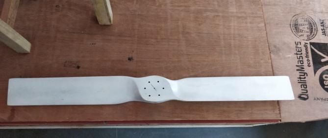
2.1 Propeller Design and Engine Selection
A two-blade propeller of diameter 1.15 m was constructed using wood. By assuming values of propeller diameter (by comparing with existing models) and by knowing the forward velocity required (design criteria), the required propellerdataisreversecalculated.
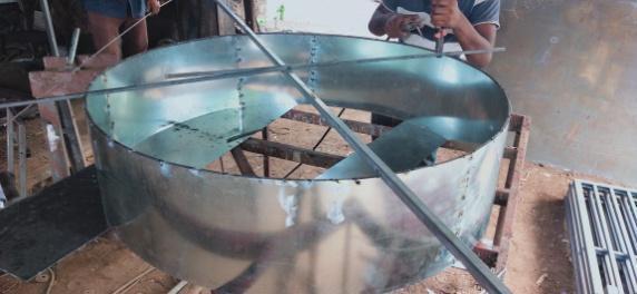
After fabricating the propeller, the casing of the propeller was designed and fabricated using sheet metal. The casing diameter was chosen as 1.16 m, in order to account for a clearanceof5mmbetweenthepropellertipandthecasing. The clearance between the casing and the tip is extremely vital; as it minimizes losses at the tip of the propeller and also reduces the free annular area that could possibly contribute to back pressures, thus affecting propeller efficiency.
Before starting fabricating the hovercraft, it was necessary to calculate the power required for the hovercraft engine. The power-to-weight ratio of the hovercraft depends on certainfactors,namely:(i)outletvelocityfromtheskirt(ii) hover height, and (iii) hull dimensions. By assuming an initialpayloadof200kg,thepowerrequiredfortheengine wascalculatedandwasfoundtobeintherangeof6to8HP.
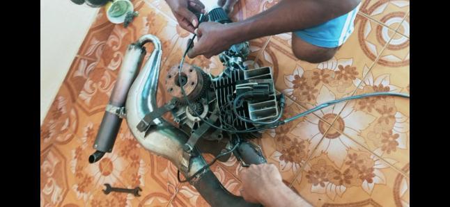
As per our initial calculations, we disassembled an enginefromaKawasakiBoxerbike.TheKawasakiBoxer engineisa4-stroke,air-cooledSIenginethatcomesata peak power of 8.2 HP at 7500 RPM. The engine has a capacity of 100 cc and produced a peak torque of 8.05 Nmat4500RPM.Thisenginewasinitiallydecidedtoact astheprimemoverofthehovercraft.Afterfurtherstudy andcalculations,itwasdeterminedthatthepowerofthe enginemustbewithintherangeof12-15HP.Thiswasin order to account for the different losses that could possibly occur considering the fact that we used an old and repeatedly driven engine. Moreover, the propeller wouldideallyrunatspeedsinthe rangeof2000 – 4000 RPM, while the Boxer engine only provides its peak power at 7500 RPM (which cannot be practically attained whiledrivingthehovercraft).Thus, wedecided to shift to a better and more powerful engine. Finally, based on our power requirements, we purchased a TVS Suzuki Shogun engine, which comes at a peak power of 14HPat8500RPMandhasacapacityof108.2ccwhile providing a peak torque of 11.4 Nm at 8250 RPM. This engine was cleaned, and then further subjected to modifications and further fine-tuned. The exhaust port diameter was increased and a C-D kit was assembled at the exhaust in order to boost engine power. Finally, the modified engine produced a power of 18-19 HP at 8500 RPM.
2.2 Cowling Duct Design and Hull Fabrication
Since the hovercraft use a single engine for bothlift and thrust, a separate system for supplying air to the hovercraft skirt was found to be necessary. Thus, a cowling duct system is used in this design to trap air fromthepropelleranddivertitintothehovercraftskirt. The area of the trap can be calculated by knowing the inlet and outlet velocities of the skirt and equating the volume flow rates into and out of the skirt. These parameters are to be finally decided only after ground testingoftheassembledengine-propellersetup..
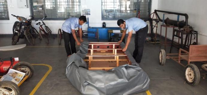
Thehullismadebyformingabaseofpolystyrenesheets above the plywood sheets. Industrial grade glue was used for the same purpose. The base of the vehicle is a combination of rectangular and semi-circular plywood pieces of width 6mm, with polystyrene sheets kept horizontal to the plywood. Another plywood sheet was adhered to on the top, and the prepared hull was kept under pressure overnight. The plywood pieces were cut according to dimensions and glue was applied to the plywood and polystyrene sheets. The dimension of the rectangular piece that made up the base was 6 feet x 4 feetand the radiusofthesemi-circularpiece was2feet. These sheets were joined with help of adhesive along witha buttjoint.Thechamberwasconstructednext,for
International Research Journal of Engineering and Technology (IRJET) e-ISSN:2395-0056
Volume: 09 Issue: 10 | Oct 2022 www.irjet.net p-ISSN:2395-0072
whichnewplywoodboardsof12mmthicknesswerejoined perpendicularlytothebase.Theheightofthischamberwas selectedtobe30cm.Fortheproperpassageofairthrough the chamber, holes of 8 cm were drilled throughout the structure. To construct this chamber, two multi-wood sheetsof6mmwidthwerebenttoformthecurvedpieceof the semicircular portion on the front side of the hull base. AllthestructureswereclampedtothebaseusingL-clamps. Inordertodistributetheloadevenlyandtosupportthetop portionofthehull,plywoodpiecesof12mmthicknesswere used to construct a frame of 5mm breadth throughout the periphery of the structure. The height of the air chamber trapping the outlet air of the propeller was calculated preciselytobeabout58cm fromthebaseofthehovercraft hull.Plywoodboardsof12mmthicknesswereusedforthe construction of this chamber. This air chamber also accounts for the support of the propeller casing and the rudderswhichareconnectedtothesteering.
Weconstructedanairbox,inordertodivert60%oftheair driven by the propeller into the duct. It was constructed with plywood of thickness of 10mm and air tightened by applying fevicol glue at the edges. A curved shape was cut intotheplywoodandPVCpieceswerefittedalongtheedges of the two curves to divert the air coming from the propeller.
base of the hovercraft hull, Washers were then fitted so asnottoleavethechainslack.Theengine,enginemount, and transmission gears were finally assembled to form the powerhouse assembly. This powerhouse assembly wasfixedonthehullusingfourM10bolts.Toabsorbthe vibrationsoftheenginefourrubberpads,apairforeach legof the mount, eachof8mmthickness,were provided betweentheenginemountbaseandhull.
2.3 Engine Assembly
The engine mount was acquired from a scrap yard, which we found to be inadequate to support the whole weight of theengine.Extramountmaterialwascutofftosaveweight and provide space for the new frame. The new frame was constructed so to support the upper part of the engine and hold two bearings that are kept parallel and aligned. The bearings house a shaft of diameter 25mm. The diameter at one endoftheshaftwas reducedto 20mmsoasto fit into thefanhub.A20mmholewasprovidedwithinthefanhub forassemblywiththeengineoutputshaft,along witha key of6mm.Thetransmissionprovidedconsistsofareduction geararrangementwithareducinggearratioof1:3fromthe engine to the propeller. The bearing and frame were constructedtokeepthis shaftataheightof0.65mfromthe
3. CALCULATIONS AND APPROXIMATIONS
Our intention was to design a hovercraft for demonstrationpurposes.soatotalweightof130kgwas considered as the design load, taking into account the weights of the base, engine, impeller, shroud, air box, steering mechanism, rudder system, engine frame, skirt, petroltank,andothermiscellaneouscomponents.
Dimensionsoftherectangularportionofhull base=6ft x4ft
Radiusofasemi-circularportionofhullbase =4ft
The cushion pressure of air in the skirt, Pc, was calculatedasfollows-
Pc = = =44.98 kg/m2 =44.98×9.81 =441.3Pa
The exit velocity from the hull air chamber to the skirt wascalculatedasfollows-
ExitVelocity(Ve)=2× =2× =77.6m/s
The hovering gap, h, (the distance above ground over which the hovercraft hovers) was taken as 0.015 m for designcalculations.
From the calculated values and the available range of engines within our budget, we decided upon a 100cc
International Research Journal of Engineering and Technology (IRJET) e-ISSN:2395-0056
Volume: 09 Issue: 10 | Oct 2022 www.irjet.net p-ISSN:2395-0072
Kawasaki Boxer engine which has the following specifications-
● Peakpower:8.2Ps(6.03kW)at7500RPM
● 8.05Nmat4500RPM
● 4 stroke, single cylinder, naturally air-cooled SI engine.
Afterfurtherstudyandcalculations,itwas determined that thepoweroftheenginemustbewithinarangeof12-15HP. Thiswastoaccountforthedifferentlossesthatcouldoccur considering that we used an old and repeatedly driven engine.Moreover,thepropellerwouldideallyrunatspeeds in the range of 2000 – 4000 RPM, while the Boxer engine onlyprovidesitspeakpowerat7500RPM(whichcannotbe practically attained while driving the hovercraft). Because of this, we decided to shift to a better and more powerful engine. We procured a more powerful, TVS Suzuki Shogun Enginewiththefollowingspecifications:
● Peakpower:14BHPat8500RPM
● 11.4Nmat8250RPM
● Displacement:108.2cc
● 4 stroke, single cylinder, naturally air-cooled SI engine.
Table -1: CalculatedDesignSpecifications
Design Specifications
Designload 130kg EnginePower 12HP
Hullbasearea 2.89m2 Engine Capacityand PeakTorque
condition at the bottom section of the control volume and wall boundary with symmetry conditions on the other three sides of the flow domain. The pattern of holeswas simulated for different positions;oncirclesof different radii from the center of the hovercraft skirt. The ideal pattern of holes would give the optimal value ofliftcoefficient,CL
Performingthissimulationgaveusabriefideaofhowair would be distributed within the skirt and how it would possibly flow through it when fully inflated. It also provided us with scope for further study of airflow withintheskirtofthehovercraft.
From analytical calculations, we evaluated the ideal position of the pattern of holes in the skirt. Referring to [2],wearrivedatamathematicalformulaforcalculating the angle through which air must deviate through the skirtholestoprovideoptimallift;givenby,
108.2cc 11.4Nmat 8250rpm
Inletvelocityof air(lift) 20m/s SkirtPerimeter 6.93m
Bysubstitutingthegivendataintheaboveequation, Hover height, h =0.015m =3.57m2 =2.89m2 t =0.5m wegotanoptimalvalueof as degrees. We then calculated the ideal position of the pattern of skirt holes in the skirt using geometric deductions, and the position of the holes was decided to be along the peripheryofacircleataradiusof19cmfromthecenter oftheskirtsection.
Escapevelocity ofair(lift) 77.6m/s Cushion Pressure (skirt)
1.16m
441.3Pa Propeller Diameter 1.15m Propeller Casing Diameter
We designed a two-dimensional skirt structure using the Designer Modeler package of ANSYS in order to study the patternofholestobemadeintheskirt.Wethenperformed the meshing of the designed two-dimensional skirt models by using projections and face mapping features, We performed a fluid flow analysis on the geometry by providing boundary conditions such as fixed wall- no-slip
Inanenginetest,weranthepropelleratvariousspeeds, from starting condition to full throttle. An anemometer was placed just behind the propeller slipstream, at various distances from the propeller center to get its velocityreadings.ThereadingsaregivenbelowinTable2.
Table -2: Slipstreamvelocityreadings
Distancefromthecenter (incm) Measuredvelocity readings(m/s) 0 4 17 20.26 32 21.6 51 13.86
© 2022, IRJET | Impact Factor value: 7.529 | ISO 9001:2008 Certified Journal | Page 338
International Research Journal of Engineering and Technology (IRJET) e-ISSN:2395-0056
Byaveragingthevaluesofvelocityfordifferentpositions, weobtainedanaveragedslipstreamvelocityvalueof17.4 m/s.
4. RESULTS AND DISCUSSION
Fromcalculations,wewereabletodeterminethatthelesser the exit velocity, the more the cushioning effect on the hovercraft. Low-speed air coming out of the air outlet hole means greater time for the air to be retained below the skirt;leadingtogreatercushioning.
Powercalculationsshowthatourhovercraftcanpossibly beliftedbya6HPengine,assumingapayloadof130kg.As the thrust for the hovercraft also comes from this engine andalsoconsideringlosses from an old engine, we decided to raise the requirement bar up to 12-13 HP. This is the reason why we finally decided not to use the Kawasaki Boxer engine, but the engine of the more powerful Shogun instead.
Bycomputationalanalysisandanalyticalcalculations,we were able to determine the optimal position of air outlets which provides the maximum and optimal value of lift coefficient. This is the position where we placed the outlet holesoftheskirtduringfabricationandtesting.
Propeller design was undertaken with utmost care. Existing propeller designs were analyzed, and the basic dimensions were decided accordingly. The propeller diameter was taken as 116 cm and a low pitch angle of 18 degreeswaschosen.Thetwo-bladeddesignwasconsidered by taking into account efficiency, cost-effectiveness, and powerrequirements.
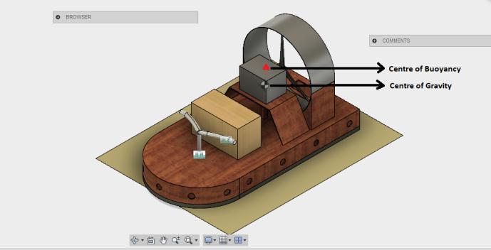
whichthevaluesofthecenterofgravity(Cg )andcenter of buoyancy (CB) were computed. This helped us design the hull of the hovercraft using stability calculations, whichensuredthatthevehiclewouldbestableduringits forwardmotionandnotslip.
(CB)
We calculated the entire weight of the system, including all components,sub-components,andsystems,andaddedtoit the passenger weight to get the total design payload. The entireloadneededtobecarefullydistributedaboutthehull of the hovercraft; for which we generated a CAD model of thedesignontheAutodesk Fusion360 Workspacethrough
5. CONCLUSIONS
Volume: 09 Issue: 10 | Oct 2022 www.irjet.net p-ISSN:2395-0072 © 2022, IRJET | Impact Factor value: 7.529 | ISO 9001:2008 Certified Journal | Page 339
Theconceptofa hovercraft isverysimple, but itsactual construction and design is an arduous task. The calculationsinvolvedarecomplexanddemandhigh-level accuracy. The weight was taken care to be evenly distributed and the center of gravity needed to be properly identified. The experience gained by doing this project gave us plenty of lessons to learn beyond the scope of a classroom. More importantly, it helped us understand a wide range of complex concepts and how to put them practically into everyday use. After fabrication, the prototype was subjected to plenty of tests and trial runs to ensure that no error went unnoticed to our attention. We designed and fabricated the hovercraft with a lot of design and budget constraints, and this was evident in the efficiency of the finalprototypeaswell.
TheprojectwascompletedwithinatotalexpenseofUSD 500 and was mostly fabricated using locally-available scrap material. We noticed that the fuel efficiency and range of the vehicle could be drastically improved if the skirt air pressure is sustained at constant levels for a prolonged duration of time with minimum losses in air leakages throughL-jointsofthehullstructure.Plywood althoughcheap,addedalotofextraweighttothedesign, thereby requiring a trade-off in the design payload for the same engine and efficiency. Through air-flow simulations, we were able to understand aspects of the hull design that could be refined further (rounding/filletingsharpedges,re-designingthecowling area) to make the hovercraft more aerodynamic and therefore,moreefficient.
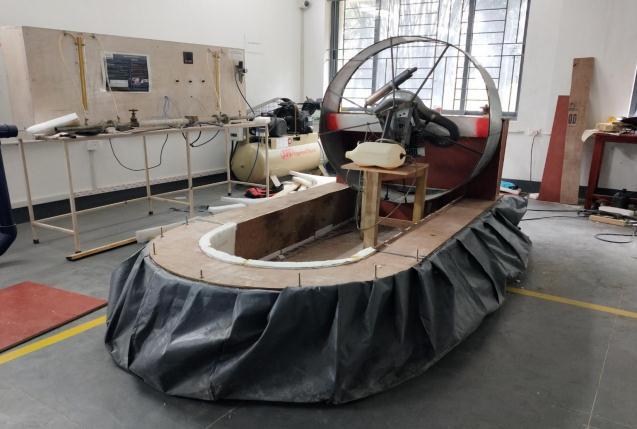
Fig -5:CADmodeloftheprototypeshowingthecomputed positionsofthecenterofgravity(Cg )andthecenterof buoyancy Fig -6:FinishedmodeloftheworkingprototypeInternational Research Journal of Engineering and Technology (IRJET) e-ISSN:2395-0056
Volume: 09 Issue: 10 | Oct 2022 www.irjet.net p-ISSN:2395-0072
In the next prototype development stage, we plan to improve the hull design with better ergonomics and aerodynamicconsiderations,usinglighterandmoredurable composites like fiber-reinforced plastics for hull construction. The two-bladed low-pitch propeller was chosen during this stage of development to be the best option due to budget constraints, however; the improved prototype is planned using a costlier, but nevertheless, a more-efficientthree-bladepropeller design.Added features like a more responsive steering system and improved braking mechanism using drag are also being designed for thenextstage.
ACKNOWLEDGEMENT
Our work has been made possible only due to the support and help from various people. This project would not be fullycompleteunlesstheircontributionsareacknowledged. Firstly, we would like to thank Rev. Fr. (Dr.) Mathew Vattathara CMI, Director, Rajagiri School of Engineering & Technology, Kochi, and Dr. A. Unnikrishnan, Principal, Rajagiri School of Engineering & Technology, Kochi for givingustheopportunitytodothiswork.Wewouldliketo express our sincere thanks to Dr. Thankachan T Pullan, Head of the Department, Department of Mechanical Engineering, Rajagiri School of Engineering & Technology, Kochi for giving us permission to do this work and for timely support whenever required. We also express our sincere gratitude to our guides, Dr. Ajithkumar A, Assistant Professor & Mr. Harikrishnan C, Assistant Professor, Department of Mechanical Engineering, Rajagiri School of Engineering & Technology, Kochi for their constant encouragement and guidance all throughout the work. We alsoexpressoursincere gratitude toourprojectevaluation committee, Dr. Joseph Babu K, Dr. Ajithkumar A. and Mr. James Mathew and all teaching and non-teaching staffs of RajagiriSchoolofEngineering&Technology,Kochi,fortheir guidanceandthetimelyhelptheyalways provided.Finally, we also thank Mr. Anand for helping us in fabricating the propeller for the hovercraft and the lab staff for helping throughoutthefabrication.
REFERENCES
[1] Cameron W. Coates, “Extracting engineering principles from a hovercraft design project for engineering sophomores”, ASME International Mechanical Engineering CongressandExposition,ProceedingsofIMECE2005,2005
[2] E L Houghton and P. W Carpenter, “Aerodynamics forengineeringstudents”,Elsevier,2003
[3] A.K.Amiruddin, S.M.Sapuan, and A.A.Jaafar, “Development of a hovercraft prototype with an aluminum hullbase.”
[4] Okiishi, Munson and Young, “Fundamentals of Fluid Mechanics, 5th Edition”, Wiley Publishing, 2005, Equation3.20,pp.122.