International Research Journal of Engineering and Technology (IRJET) e-ISSN: 2395-0056

Volume: 09 Issue: 10 | Oct 2022 www.irjet.net p-ISSN: 2395-0072

International Research Journal of Engineering and Technology (IRJET) e-ISSN: 2395-0056
Volume: 09 Issue: 10 | Oct 2022 www.irjet.net p-ISSN: 2395-0072
,
1UG scholar, Department of Mechanical Engineering, India
2Associate Professor, Department of Automobile Engineering, India Maturi Venkata Subba Rao (MVSR) Engineering College, Telangana, India Email: apavanchaitanya.01@gmail.com, bhod_auto@mvsrec.edu.in ***
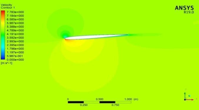
This study investigates the factors influencing the performance of an aerofoil that is intended to be used in a flight system. Wind speed and angle of attack parameters are crucial for perfect flight. The inlet flow velocity along the surface of the aerofoil geometry is varied from 5 to 25m/s with 5m/s interval. Here, a numerical investigation using ANSYS Fluent, of two-dimensional incompressible flow over a NACA 0006 aerofoil is analysed at various mach numbers by varying angle of attack. The purpose of this research is to study the flow pattern over an aerofoil using CFD. Variation of pressure and velocity counters are plotted. The variations in coefficient of lift and coefficient of drag with respect to various angles of attack is analysed.
Key Words- NACA 0006 aerofoil, coefficient of lift and drag, angle of attack, pressure and velocity counters
The method of simulating a fluid flow mathematically related to a physical event and solving it numerically utilizing computational power is known as computational fluid dynamics (CFD). It is undertaken to examine fluid flow in relation to its physical characteristics such as velocity, pressure, density, and viscosity. Those features must be taken into account simultaneouslyinordertopracticallydevelopanprecise solution for a physical phenomenon connected to fluid flow.
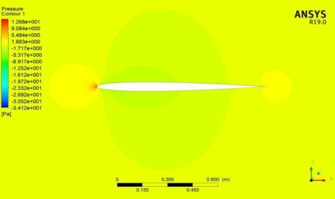
To analyse fluid flow, a CFD software tool employs a numerical method and mathematical model. The pressure distribution over the aerofoil surface often affects both the lift force and the pitching moment. The distribution of friction and pressure along the surface affectsthedragforce.
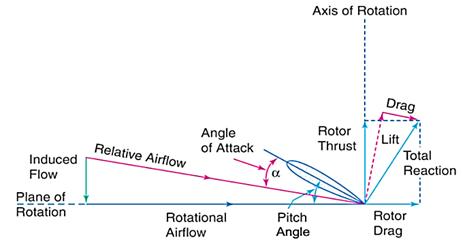
Dimensionless coefficients are taken into account in comparisonsandassessmentsduetothediverseshapes and sizes of the aerofoil created for distinct purposes. The result of the wing's motion in free stream is a lift force that is perpendicular to its motion and larger than the downward gravity force on the wing, keeping the aircraft in the air. The effective wing area that faces the airflow directly affects drag, as does the shape of the wing.Theangleofattackbetweenthewing'sdirectionof flight and the chord line of the blade influences the lift anddrag.
The following two-dimensional calculations were made toaccountfor equation(1)and equation(2)inthe performance assessment of the airfoils. L (the L lift force),D(theDdragforce),V(theVwindspeed),ρ(the ρ fluid density), and S are additional factors in the equation (the S aerofoil surface area). Following the dimensionless calculation of these factors, the CL/CD ratio can be practically applied for performance comparisons.
The surface curve coordinates that define the typical NACA0006bladegeometrywereimportedtocreatethe blade section geometry. The properties of the
International Research Journal of Engineering and Technology (IRJET) e-ISSN: 2395-0056
Volume: 09 Issue: 10 | Oct 2022 www.irjet.net p-ISSN: 2395-0072
aerodynamic system have been examined using computationalfluiddynamics(CFD).
NACAaerofoilsarethosethathavebeenstandardisedby the National Advisory Committee for Aeronautics (NACA). Their geometries are defined by a series of digits. NACA aerofoils come in four-digit, five-digit, oneseries,andothervariations.Inthisstudy,oneofthefourdigitNACAprofiles,NACA0006,isselectedandtestedin theanalysis.The"00"firstdigitsofthewingindicatethat it lacks camber and has a symmetrical profile. The thickness to chord length ratio is represented by the otherdigits"06."Thethicknessofthewingis6%[1],[2]. Itsformisencodedinanequation.[3]isthesymmetrical four-digitNACAaerofoil. [ √ ( ) ( ) ( ) ] (3)
Where:
"yt"isthehalf-thicknessoftheaerofoil
"t"isthemaximumthickness
"c"isthechordlength "x"istheposition
[4]hasresearchedontheeffectofliftanddrag using typical root aerofoil section of Boeing 737 aircraft wing model for various angles ranging from to usingCFDandalsoanalysedadverse parametersofstall angleandyawfortestaerofoil.
B S Gawali and Pravin Mane [5] An experimental and Computational analysis (CFD) was performed at an air flowrateof15m/soveranaerofoilatdifferentanglesof attack ranging from to . The findings of the study demonstratedthepressuredistributionovertheaerofoil aswellastheactionofliftforceontheaerofoil.
Rajat, Kiran, Vipul, Pritam [6] analysed the aerofoil over 2D subsonic flow at a varying angle of attack that is operating at Reynolds’s number were obtained and concluded that flow has occured separation away from therearedgethatreducesthegeneratedlift
Karna, Saumil, Utsav, Prof. Ankit analytically analysed the 2D subsonic flow at varying angle of attack working ataReof3×E+06onNACA0012aerofoil[7]
The XY plane has been chosen to build the aerofoil and fluiddomainmodels.TheCartesiancoordinatesof NACA 0006aerofoilhavebeenimportedfromtheUIUCaerofoil database[8].Theaerofoilhasapproximately1mofchord length. The C-type fluid domain of 10C has been constructedintheDesignModellerofANSYSworkbench. In order to have greater control over the mesh generation,thedomainhasbeenslicedintofoursurfaces by drawing a horizontal line through the aerofoil and vertical line at the straggling edge of the aerofoil. The projection tool has been selected to project the four surfacesontothefluiddomain.
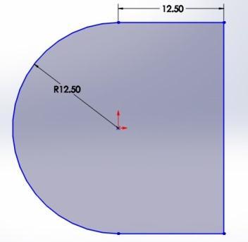
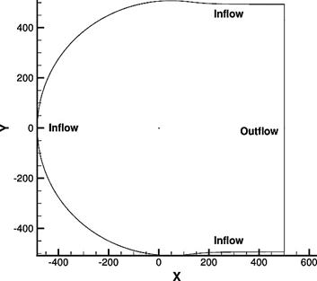
FarFieldmeshiscreatedusingtheDesignModellerwith dimensionsof12.5minradiusandlength.Thecurvature part is taken as inlet and the sides as walls, end line as outlet.
Chord(mm) –100
Radius(mm)– 0
Origin(%)– 0
Pitch(°) – 0
Fig.2. FarFieldMeshSketch(inm)
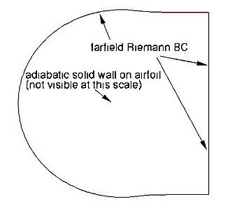
Fig.3. FarFieldBCdescription
International Research Journal of Engineering and Technology (IRJET) e-ISSN: 2395-0056
Volume: 09 Issue: 10 | Oct 2022 www.irjet.net p-ISSN: 2395-0072
Fig.4. FarFieldBCflowdescription
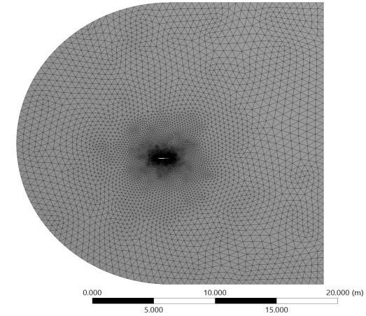
In the finite element method, the fluid domain discretized into smaller elements based on a specific shape.TheTriangularstructuredmeshhasbeenapplied in the fluid domain as it can provide better accuracy comparedtotheunstructuredmesh.
Theaerofoilhasbeeninitializedasno-slipandtreatedas wall boundary as the flow energy has been lost into dissipation and brought to rest as it approached the surface. The flow whose density remained unchanged is definedastheincompressibleflowisdefinedastheflow that has constant density and Mach number M<=0.3. Therefore, the constant air density has been set as the materialofthefluid.Thevelocityinlethasbeensetfrom 5 - 25 m/s, which was equivalent to a Mach number of 0.01-0.07.
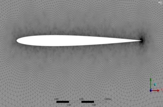
Triangular Mesh with suitable Refinements and Sizing was used for generating mesh to improve the quality of theoutput.Inflationwasestablishedaroundtheaerofoil curve.
Forturbulentflowconditions,tosimulatecharacteristics of mean flow the most commonly used model in CFD is thek-epsilon(k- )turbulencemodelsuitable.
It is a model that uses two transport equations to provide a general elucidation of turbulence. A new generationofequationforturbulentviscosityisincluded intherealisablek- model
Compressibility has an impact on turbulence at high Mach numbers through a process known as "dilatation dissipation," which is typically overlooked in the modellingofincompressibleflows.Theobserveddropin spreading rate with rising Mach number for compressible mixing and other free shear layers cannot be predicted without taking into account dilatation dissipation.[9]
(4)
Where, istheturbulentMachnumber,definedas √ (5)
Where,a( √ )isthespeedofsound.
Thiscompressibilitymodificationalwaysapplieswhen theidealgaslawisappliedinitscompressibleform.
The modelled transport equations for k and in the realizable modelare ( ) [( ) ] (6)
International Research Journal of Engineering and Technology (IRJET) e-ISSN: 2395-0056
Volume: 09 Issue: 10 | Oct 2022 www.irjet.net p-ISSN: 2395-0072
Equation4 describes the generation of turbulence kinetic energy due to the mean velocity gradients denoted as Equation5 describes the generation of turbulence kinetic energy due to buoyancy signified as
For and k, the turbulent Prandtl numbers are and Some user-defined source terms are and .[9]
K-Epsilon(2eqn)
C2–Epsilon - 1.9
TKEPrandtlNumber - 1
TDRPrandtlNumber - 1.2
K-EpsilonModel - Realizable Near-WallTreatment StandardWallFunctions Viscosity(kg/m-s)-1.7894e-05
300k
Fig.8.
Fig.9.
Fig.10.
International Research Journal of Engineering and Technology (IRJET) e-ISSN: 2395-0056
Table 1. DepictingMin/Maxvalues
Contour Min value Max value
Density(kg ) 1.225 1.225
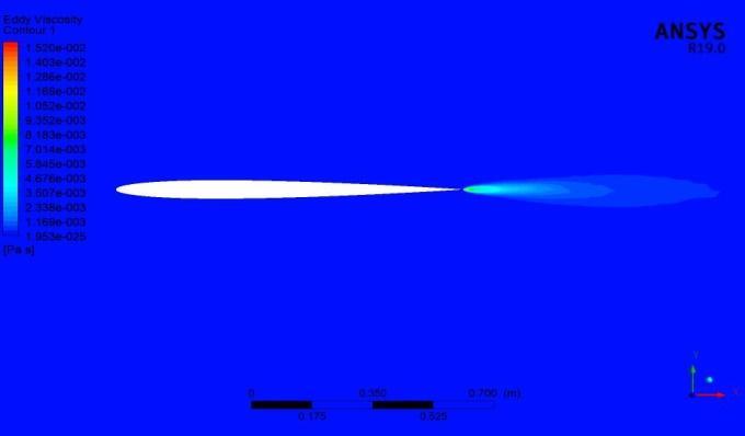
EddyViscosity(Pas) 1.9527e-25 0.0155868
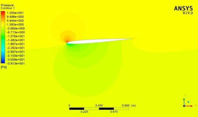
Pressure(Pa) -34.1172 13.8837 Pressure.Gradient (kg ) 3.28287e-05 5.63732e+06
TurbulenceEddy Dissipation( ) 9.30091e-07 1.85124e+08
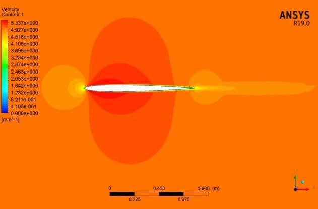
TurbulenceKinetic Energy( ) 1e-14 89.7405 Velocity(m/s) 0 5.47391 WallShear(Pa) 0.000235352 9.62613
Table 2. Coefficientofliftanddragforvaryingangleof attack(AoA)atInletvelocityof5m/s
Angle of Attack (°) Coefficient of Lift ( ) Coefficient of Drag ( ) ⁄
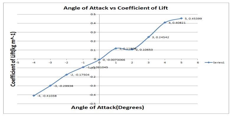
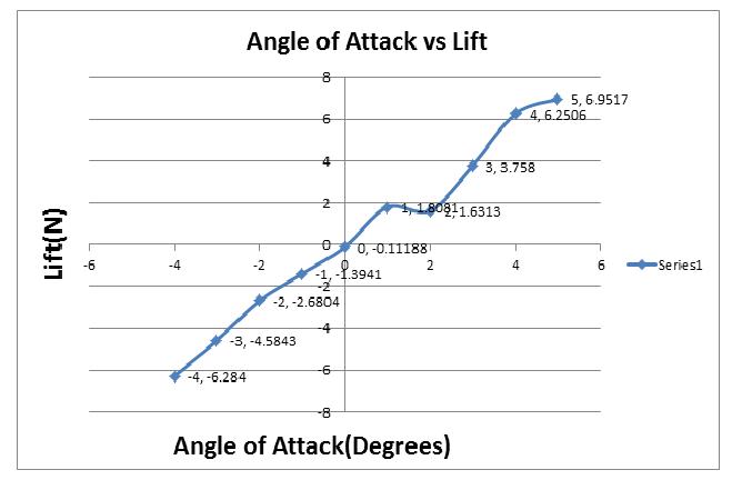
-4 -0.41038 0.015111 -27.15769969 -3 -0.29938 0.013874 -21.57849214 -2 -0.17504 0.013087 -13.37510507 -1 -0.091045 0.012463 -7.305223461 0 -0.0073066 0.01644 -0.444440389 1 0.11808 0.012196 9.681862906 2 0.10653 0.012509 8.516268287 3 0.24542 0.014442 16.99349121 4 0.40821 0.016606 24.58207877 5 0.45399 0.017987 25.23989548
Table 3. Coefficientofliftanddragforvaryingangleof attack(AoA)atInletvelocityof25m/s
Angle of Attack (°) Coefficient of Lift ( ) Coefficient of Drag ( ) ⁄
-4 -0.37186 0.012621 -29.46359243 -3 -0.27619 0.011291 -24.46107519 -2 -0.10329 0.017134 -6.028364655 -1 -0.061246 0.0095662 -6.402333215 0 -0.0034407 0.0091379 -0.376530713
1 0.20387 0.0085699 23.78907572 2 0.08704 0.010045 8.665007466 3 0.2037 0.011288 18.04571226 4 0.42534 0.014461 29.41290367 5 0.51777 0.013938 37.14808437
Fig.12. GraphAOAvsLiftat5m/s
Fig.13. AOAvsCoefficientofLiftat5m/s
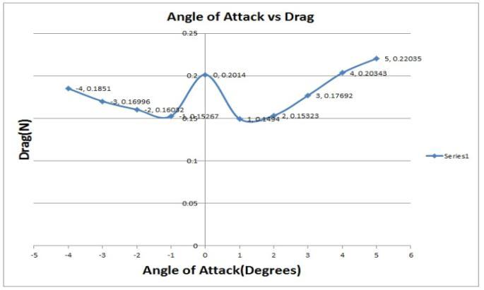
Fig.14. AOAvsDragat5m/s
Volume: 09 Issue: 10 | Oct 2022 www.irjet.net p-ISSN: 2395-0072 © 2022, IRJET | Impact Factor value: 7.529 | ISO 9001:2008 Certified Journal | Page1031
International Research Journal of Engineering and Technology (IRJET) e-ISSN: 2395-0056
Volume: 09 Issue: 10 | Oct 2022 www.irjet.net p-ISSN: 2395-0072
Fig.18. AOAvsDragat25m/s
Fig.15. AOAvsCoefficientofDragat5m/s
Fig.16. AOAvsLiftat25m/s
Fig.19. AOAvsCoefficientofDragat25m/s
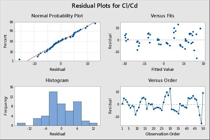
A simple technique for determining the functional relationship between variables and the influence of variables on response is known as regression analysis. ThisanalysisiscarriedoutusingtheMiniTabsoftware.
Using regression analysis as equation 8-10, a mathematical model is created. The developed equation is based on simulated data, with the response represented by the ratio of coefficient of lift ) to coefficient of drag ( ) and the dependent variable representedbytheangleofattack.
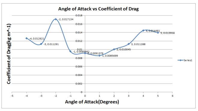
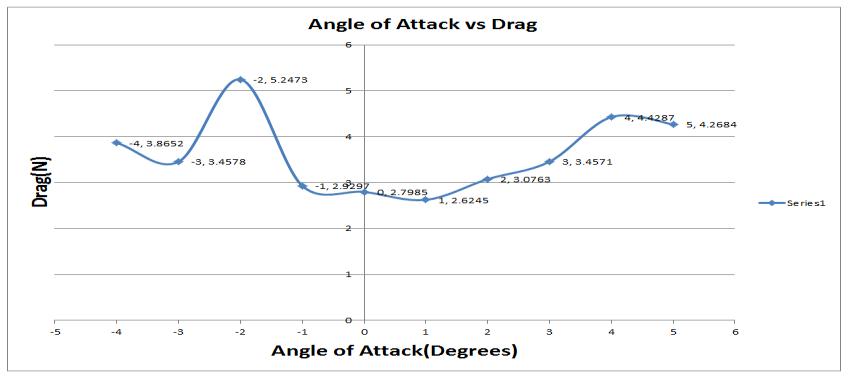
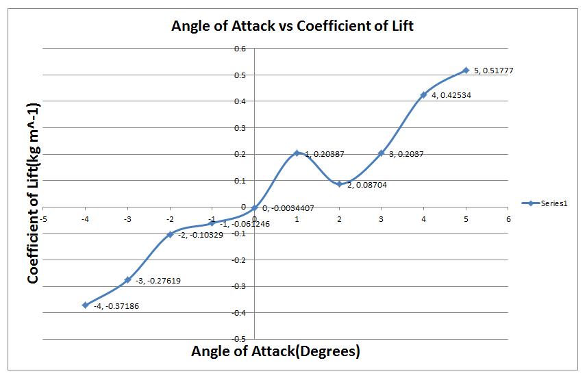
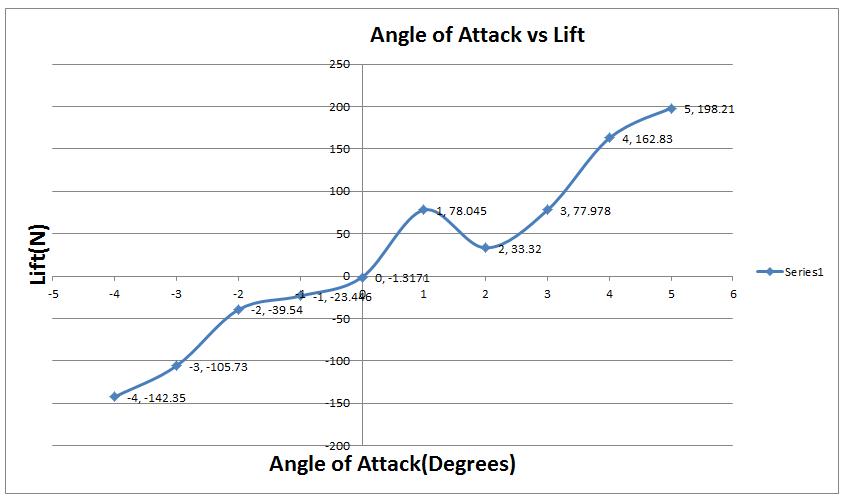
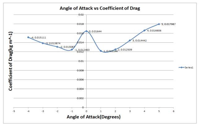
Fig.17. AOAvsCoefficientofLiftat25m/s
2022, IRJET | Impact Factor value: 7.529 | ISO 9001:2008 Certified Journal |
International Research Journal of Engineering and Technology (IRJET) e-ISSN: 2395-0056
Volume: 09 Issue: 10 | Oct 2022 www.irjet.net p-ISSN: 2395-0072
R-sq(adj) =93.3%
Residual plots for Cl/Cd
Regression Equation
Cl/Cd = 3.83 +5.670 AoA - 0.337 InletVelocity +0.0407 AoA InletVelocity -0.409AoA AoA +0.0146 InletVelocity InletVelocity (8)
Model Summary
S = 5.66958
R-sq = 91.25% R-sq(adj) =90.26%
Fig.21. Coefficientoflift ( )datafittedtomathematical curve
Regression Equation
Cl = 0.02182 + 0.07704 AoA - 0.00313 + 0.000611 (9)
Model Summary
S = 0.0647694 R-sq = 93.7%
value:
Fig.22. Coefficientoflift ( )toCoefficientofdrag ( ) Cl/Cddatafittedtomathematicalcurve
Regression Equation
Cl/Cd = 2.549 + 6.775 AoA - 0.3554 + 0.03554 (10)
Model Summary
S = 5.68234
R-sq = 90.8% R-sq(adj) =90.2%
Withincreaseinangleofattackitisobservedthatlifthas increased and peaked at 5°, whereas at 0° the drag is greaterthanliftwhichisnotpreferredinaircraftsasthe mainaimistoreducethedrag.1°AoAispreferredover 2°astheliftproducedisslightlygreater,atnegativeAoA of-2°dragispeaked.Theseresultsareanalysedwiththe standard NACA 0006 aerofoil. The aerofoil is best suitableforhigherangleofattack.
At higher AoA better lift can be obtained by using this aerofoilso,thefuel efficiencywill beimproved byabout 8%. The simulated value of the coefficient of lift is in good fit and with high accuracy to the mathematical model equation. This aerofoil is well pereferred at 5° AoA as drag is less, where the flight will emit less pollutionandcanbeconsideredgreenflight.
[1] “NACA Airfoils | NASA,” 2017. https://www.nasa.gov/imagefeature/langley/100/nacaairfoils (accessed Jan. 19, 2021).
International Research Journal of Engineering and Technology (IRJET) e-ISSN: 2395-0056 Volume: 09 Issue: 10 | Oct 2022 www.irjet.net p-ISSN: 2395-0072
[2] Jacobs J. N., Ward K. E., and Careas R. M., “The Characteristics of 78 Related Airfoil Sections Sections From Tests In The Variable-Density Wind Tunnel,” NationalAdvisoryCommiteeforAeronautics,(1935).
[3] Anderson J. D., Fundamentals of Aerodynamics SI, McGraw-Hill,1984(3),(2011).
[4]Shubham Prakash Rawool ,“CFD analysis ofboeing7373daerofoilandadverseyawontheaerofoil”,,IJRET: International Journal of Research in Engineering and Technology,Vol 6,Issue6,(2017),2321-7308.
[5] Chandrakant Sagat, Pravin Mane and B S Gawali, ExperimentalandCFDanalysisofairfoilatlowReynolds number,InternationalJournalofMechanicalEngineering and Robotics Research, ISSN 2278 – 0149 Vol. 1, No. 3, October2012
[ ]Rajat Veer, Kiran Shinde, Vipul Gaikwad, Pritam Sonawane , “Study and Analyse Airfoil Section using CFD”, International Journal of Engineering Research & Technology(IJERT),Vol.6Issue09,(2017)2278-0181.
[7] Karna S. Patel, Saumil B. Patel, Utsav B. Patel, Prof. Ankit P. Ahuja, “CFD Analysis of an Aerofoil”, International Journal of Engineering Research Volume No.3,IssueNo.3,(2014)2319-6890.
[8] “Airfoil Tools.” http://airfoiltools.com/ (accessed Feb.04,2021).
[9]Ansys Inc., “Ansys Fluent 12.0/12.1 Documentation” AnsysInc.,(12.0)
2022, IRJET | Impact Factor value: 7.529 | ISO 9001:2008 Certified Journal | Page1034